EP4017696B1 - Vorrichtung und verfahren zur herstellung von mikrostrukturen - Google Patents
Vorrichtung und verfahren zur herstellung von mikrostrukturen Download PDFInfo
- Publication number
- EP4017696B1 EP4017696B1 EP20761166.6A EP20761166A EP4017696B1 EP 4017696 B1 EP4017696 B1 EP 4017696B1 EP 20761166 A EP20761166 A EP 20761166A EP 4017696 B1 EP4017696 B1 EP 4017696B1
- Authority
- EP
- European Patent Office
- Prior art keywords
- hollow cylinder
- plunger
- female mold
- die
- rests
- Prior art date
- Legal status (The legal status is an assumption and is not a legal conclusion. Google has not performed a legal analysis and makes no representation as to the accuracy of the status listed.)
- Active
Links
Images

Classifications
-
- B—PERFORMING OPERATIONS; TRANSPORTING
- B29—WORKING OF PLASTICS; WORKING OF SUBSTANCES IN A PLASTIC STATE IN GENERAL
- B29C—SHAPING OR JOINING OF PLASTICS; SHAPING OF MATERIAL IN A PLASTIC STATE, NOT OTHERWISE PROVIDED FOR; AFTER-TREATMENT OF THE SHAPED PRODUCTS, e.g. REPAIRING
- B29C43/00—Compression moulding, i.e. applying external pressure to flow the moulding material; Apparatus therefor
- B29C43/32—Component parts, details or accessories; Auxiliary operations
- B29C43/36—Moulds for making articles of definite length, i.e. discrete articles
- B29C43/361—Moulds for making articles of definite length, i.e. discrete articles with pressing members independently movable of the parts for opening or closing the mould, e.g. movable pistons
-
- B—PERFORMING OPERATIONS; TRANSPORTING
- B29—WORKING OF PLASTICS; WORKING OF SUBSTANCES IN A PLASTIC STATE IN GENERAL
- B29C—SHAPING OR JOINING OF PLASTICS; SHAPING OF MATERIAL IN A PLASTIC STATE, NOT OTHERWISE PROVIDED FOR; AFTER-TREATMENT OF THE SHAPED PRODUCTS, e.g. REPAIRING
- B29C33/00—Moulds or cores; Details thereof or accessories therefor
- B29C33/42—Moulds or cores; Details thereof or accessories therefor characterised by the shape of the moulding surface, e.g. ribs or grooves
-
- B—PERFORMING OPERATIONS; TRANSPORTING
- B29—WORKING OF PLASTICS; WORKING OF SUBSTANCES IN A PLASTIC STATE IN GENERAL
- B29C—SHAPING OR JOINING OF PLASTICS; SHAPING OF MATERIAL IN A PLASTIC STATE, NOT OTHERWISE PROVIDED FOR; AFTER-TREATMENT OF THE SHAPED PRODUCTS, e.g. REPAIRING
- B29C43/00—Compression moulding, i.e. applying external pressure to flow the moulding material; Apparatus therefor
- B29C43/02—Compression moulding, i.e. applying external pressure to flow the moulding material; Apparatus therefor of articles of definite length, i.e. discrete articles
- B29C43/021—Compression moulding, i.e. applying external pressure to flow the moulding material; Apparatus therefor of articles of definite length, i.e. discrete articles characterised by the shape of the surface
-
- B—PERFORMING OPERATIONS; TRANSPORTING
- B29—WORKING OF PLASTICS; WORKING OF SUBSTANCES IN A PLASTIC STATE IN GENERAL
- B29C—SHAPING OR JOINING OF PLASTICS; SHAPING OF MATERIAL IN A PLASTIC STATE, NOT OTHERWISE PROVIDED FOR; AFTER-TREATMENT OF THE SHAPED PRODUCTS, e.g. REPAIRING
- B29C43/00—Compression moulding, i.e. applying external pressure to flow the moulding material; Apparatus therefor
- B29C43/02—Compression moulding, i.e. applying external pressure to flow the moulding material; Apparatus therefor of articles of definite length, i.e. discrete articles
- B29C43/027—Compression moulding, i.e. applying external pressure to flow the moulding material; Apparatus therefor of articles of definite length, i.e. discrete articles having an axis of symmetry
-
- A—HUMAN NECESSITIES
- A61—MEDICAL OR VETERINARY SCIENCE; HYGIENE
- A61M—DEVICES FOR INTRODUCING MEDIA INTO, OR ONTO, THE BODY; DEVICES FOR TRANSDUCING BODY MEDIA OR FOR TAKING MEDIA FROM THE BODY; DEVICES FOR PRODUCING OR ENDING SLEEP OR STUPOR
- A61M37/00—Other apparatus for introducing media into the body; Percutany, i.e. introducing medicines into the body by diffusion through the skin
- A61M37/0015—Other apparatus for introducing media into the body; Percutany, i.e. introducing medicines into the body by diffusion through the skin by using microneedles
- A61M2037/0046—Solid microneedles
-
- A—HUMAN NECESSITIES
- A61—MEDICAL OR VETERINARY SCIENCE; HYGIENE
- A61M—DEVICES FOR INTRODUCING MEDIA INTO, OR ONTO, THE BODY; DEVICES FOR TRANSDUCING BODY MEDIA OR FOR TAKING MEDIA FROM THE BODY; DEVICES FOR PRODUCING OR ENDING SLEEP OR STUPOR
- A61M37/00—Other apparatus for introducing media into the body; Percutany, i.e. introducing medicines into the body by diffusion through the skin
- A61M37/0015—Other apparatus for introducing media into the body; Percutany, i.e. introducing medicines into the body by diffusion through the skin by using microneedles
- A61M2037/0053—Methods for producing microneedles
-
- B—PERFORMING OPERATIONS; TRANSPORTING
- B29—WORKING OF PLASTICS; WORKING OF SUBSTANCES IN A PLASTIC STATE IN GENERAL
- B29C—SHAPING OR JOINING OF PLASTICS; SHAPING OF MATERIAL IN A PLASTIC STATE, NOT OTHERWISE PROVIDED FOR; AFTER-TREATMENT OF THE SHAPED PRODUCTS, e.g. REPAIRING
- B29C43/00—Compression moulding, i.e. applying external pressure to flow the moulding material; Apparatus therefor
- B29C43/02—Compression moulding, i.e. applying external pressure to flow the moulding material; Apparatus therefor of articles of definite length, i.e. discrete articles
- B29C43/021—Compression moulding, i.e. applying external pressure to flow the moulding material; Apparatus therefor of articles of definite length, i.e. discrete articles characterised by the shape of the surface
- B29C2043/023—Compression moulding, i.e. applying external pressure to flow the moulding material; Apparatus therefor of articles of definite length, i.e. discrete articles characterised by the shape of the surface having a plurality of grooves
- B29C2043/025—Compression moulding, i.e. applying external pressure to flow the moulding material; Apparatus therefor of articles of definite length, i.e. discrete articles characterised by the shape of the surface having a plurality of grooves forming a microstructure, i.e. fine patterning
-
- B—PERFORMING OPERATIONS; TRANSPORTING
- B29—WORKING OF PLASTICS; WORKING OF SUBSTANCES IN A PLASTIC STATE IN GENERAL
- B29C—SHAPING OR JOINING OF PLASTICS; SHAPING OF MATERIAL IN A PLASTIC STATE, NOT OTHERWISE PROVIDED FOR; AFTER-TREATMENT OF THE SHAPED PRODUCTS, e.g. REPAIRING
- B29C43/00—Compression moulding, i.e. applying external pressure to flow the moulding material; Apparatus therefor
- B29C43/02—Compression moulding, i.e. applying external pressure to flow the moulding material; Apparatus therefor of articles of definite length, i.e. discrete articles
- B29C43/027—Compression moulding, i.e. applying external pressure to flow the moulding material; Apparatus therefor of articles of definite length, i.e. discrete articles having an axis of symmetry
- B29C2043/029—Compression moulding, i.e. applying external pressure to flow the moulding material; Apparatus therefor of articles of definite length, i.e. discrete articles having an axis of symmetry using axial compression along a longitudinal axis
-
- B—PERFORMING OPERATIONS; TRANSPORTING
- B29—WORKING OF PLASTICS; WORKING OF SUBSTANCES IN A PLASTIC STATE IN GENERAL
- B29C—SHAPING OR JOINING OF PLASTICS; SHAPING OF MATERIAL IN A PLASTIC STATE, NOT OTHERWISE PROVIDED FOR; AFTER-TREATMENT OF THE SHAPED PRODUCTS, e.g. REPAIRING
- B29C59/00—Surface shaping of articles, e.g. embossing; Apparatus therefor
- B29C59/02—Surface shaping of articles, e.g. embossing; Apparatus therefor by mechanical means, e.g. pressing
- B29C59/022—Surface shaping of articles, e.g. embossing; Apparatus therefor by mechanical means, e.g. pressing characterised by the disposition or the configuration, e.g. dimensions, of the embossments or the shaping tools therefor
- B29C2059/023—Microembossing
-
- B—PERFORMING OPERATIONS; TRANSPORTING
- B29—WORKING OF PLASTICS; WORKING OF SUBSTANCES IN A PLASTIC STATE IN GENERAL
- B29C—SHAPING OR JOINING OF PLASTICS; SHAPING OF MATERIAL IN A PLASTIC STATE, NOT OTHERWISE PROVIDED FOR; AFTER-TREATMENT OF THE SHAPED PRODUCTS, e.g. REPAIRING
- B29C33/00—Moulds or cores; Details thereof or accessories therefor
- B29C33/38—Moulds or cores; Details thereof or accessories therefor characterised by the material or the manufacturing process
- B29C33/40—Plastics, e.g. foam or rubber
- B29C33/405—Elastomers, e.g. rubber
-
- B—PERFORMING OPERATIONS; TRANSPORTING
- B29—WORKING OF PLASTICS; WORKING OF SUBSTANCES IN A PLASTIC STATE IN GENERAL
- B29K—INDEXING SCHEME ASSOCIATED WITH SUBCLASSES B29B, B29C OR B29D, RELATING TO MOULDING MATERIALS OR TO MATERIALS FOR MOULDS, REINFORCEMENTS, FILLERS OR PREFORMED PARTS, e.g. INSERTS
- B29K2005/00—Use of polysaccharides or derivatives as moulding material
-
- B—PERFORMING OPERATIONS; TRANSPORTING
- B29—WORKING OF PLASTICS; WORKING OF SUBSTANCES IN A PLASTIC STATE IN GENERAL
- B29K—INDEXING SCHEME ASSOCIATED WITH SUBCLASSES B29B, B29C OR B29D, RELATING TO MOULDING MATERIALS OR TO MATERIALS FOR MOULDS, REINFORCEMENTS, FILLERS OR PREFORMED PARTS, e.g. INSERTS
- B29K2039/00—Use of polymers with unsaturated aliphatic radicals and with a nitrogen or a heterocyclic ring containing nitrogen in a side chain or derivatives thereof as moulding material
- B29K2039/06—Polymers of N-vinyl-pyrrolidones
-
- B—PERFORMING OPERATIONS; TRANSPORTING
- B29—WORKING OF PLASTICS; WORKING OF SUBSTANCES IN A PLASTIC STATE IN GENERAL
- B29K—INDEXING SCHEME ASSOCIATED WITH SUBCLASSES B29B, B29C OR B29D, RELATING TO MOULDING MATERIALS OR TO MATERIALS FOR MOULDS, REINFORCEMENTS, FILLERS OR PREFORMED PARTS, e.g. INSERTS
- B29K2067/00—Use of polyesters or derivatives thereof, as moulding material
- B29K2067/04—Polyesters derived from hydroxycarboxylic acids
-
- B—PERFORMING OPERATIONS; TRANSPORTING
- B29—WORKING OF PLASTICS; WORKING OF SUBSTANCES IN A PLASTIC STATE IN GENERAL
- B29K—INDEXING SCHEME ASSOCIATED WITH SUBCLASSES B29B, B29C OR B29D, RELATING TO MOULDING MATERIALS OR TO MATERIALS FOR MOULDS, REINFORCEMENTS, FILLERS OR PREFORMED PARTS, e.g. INSERTS
- B29K2995/00—Properties of moulding materials, reinforcements, fillers, preformed parts or moulds
- B29K2995/0037—Other properties
- B29K2995/0094—Geometrical properties
-
- B—PERFORMING OPERATIONS; TRANSPORTING
- B29—WORKING OF PLASTICS; WORKING OF SUBSTANCES IN A PLASTIC STATE IN GENERAL
- B29L—INDEXING SCHEME ASSOCIATED WITH SUBCLASS B29C, RELATING TO PARTICULAR ARTICLES
- B29L2031/00—Other particular articles
- B29L2031/753—Medical equipment; Accessories therefor
- B29L2031/7544—Injection needles, syringes
-
- B—PERFORMING OPERATIONS; TRANSPORTING
- B29—WORKING OF PLASTICS; WORKING OF SUBSTANCES IN A PLASTIC STATE IN GENERAL
- B29L—INDEXING SCHEME ASSOCIATED WITH SUBCLASS B29C, RELATING TO PARTICULAR ARTICLES
- B29L2031/00—Other particular articles
- B29L2031/756—Microarticles, nanoarticles
Definitions
- the invention relates to a device and a method for producing microstructures, in particular microneedles.
- microneedles are used to deliver active ingredients directly into the skin, also known as transdermal administration.
- the microneedles are just long enough to penetrate only the outer layers of the skin, but preferably do not reach nerves and blood vessels and thus leave them unharmed. Nevertheless, microneedles create small holes in the upper layers of the skin, which significantly increases the absorption of active ingredients compared to a purely external application of active ingredients to the skin.
- Microneedle arrays which have a large number of microneedles, for example attached to a carrier surface, can be used for short-term administration or for long-term application.
- a preferred way of delivering active substances from the microneedles into the skin is for active substance-containing areas of the microneedles or the entire microneedle to dissolve or detach and thus be absorbed by the body through the skin.
- the microneedles are made in particular, at least partially, from water-soluble substances or materials.
- the microneedles it is also possible for the microneedles to have pores or cavities or to be designed as hollow needles in order to achieve such a To enable the active ingredient to be delivered to the skin.
- microneedles can also be free of active ingredients.
- the active ingredient can be applied externally to the outside of the microneedles, for example, or a substance containing the active ingredient can be applied to the relevant area of skin only after the microneedles have been removed from the skin in order to administer active ingredients using microneedles.
- Microneedles can be made of ceramic, metal or polymer, among other things. It is preferred that one or more active ingredients are added to these materials, thus resulting in a formulation of microneedles.
- a common method for producing microneedles is to cast the microneedles or entire microneedle arrays, for example using a silicone mold.
- the tolerances to be maintained for the microneedles are extremely low.
- correspondingly low tolerances must be ensured for the matrices, i.e. in particular silicone molds, and on the other hand, the manufacturing processes must also be carried out with correspondingly low tolerances.
- microneedles require aseptic processing, as the active ingredient must be processed openly in the production environment. Subsequent sterilization is not possible for many active ingredients. This creates the need for aseptic production, in which sterile disposable products The use of sterile, disposable products prevents the risk of contamination.
- a device and a method for producing a microneedle array are known.
- a mold has needle-shaped depressions.
- material is pressed into the depressions.
- the back is then pressed with a layer of PMMA.
- the active ingredient is applied to the top side, which faces away from the needles, and diffuses in the direction of the needles.
- the object of the invention is to provide a device and a method for producing microstructures, in particular microneedles, with which microstructures can be produced with very small tolerances.
- the object is achieved according to the invention by a device according to claim 1 or a method according to claim 11.
- the device according to the invention is used in particular for producing microstructures that dissolve, such as microneedles, and particularly preferably for producing microneedle arrays.
- the device has a matrix that has at least one, preferably conical, depression on its upper side.
- the depression is used to produce the microstructure, in particular in a casting process, i.e. by metering and distributing a mostly liquid formulation onto the upper side of the matrix, and hardening it to produce the microstructure.
- the device also has a hollow cylinder.
- This is preferably part of a base element or forms a base element.
- the die has a holding element or is connected to a holding element so that the die can be fastened or held on the hollow cylinder.
- the matrix spans or covers an opening of the hollow cylinder.
- the matrix rests against the edge of the opening of the hollow cylinder in an initial state or in a resting state before the matrix is used or filled with a formulation.
- the hollow cylinder is in particular a cylinder with a circular cross-section.
- a plunger is arranged in the hollow cylinder. This is displaceable in the longitudinal direction of the hollow cylinder.
- the plunger can be moved from a Starting or resting position, the die can be pushed into the hollow cylinder in an inserted or upper position so that an upper side of the plunger rests on an underside of the die, with the underside of the die pointing towards the interior of the hollow cylinder. It is particularly preferred here for the plunger to be pushed far enough into the hollow cylinder that the die no longer touches the edge of the opening of the hollow cylinder, but is lifted off it. This makes it possible to achieve small tolerances.
- the invention has the significant advantage that by pushing the plunger into the hollow cylinder in such a way that the die only rests on the upper side of the plunger, any tolerances that may accumulate can be reduced.
- the tolerance of the thickness of the die is relevant. Tolerances that would be caused by the hollow cylinder are thus excluded. This allows a lower tolerance quality of the hollow cylinders and their holding element, since the process tolerance is created via the rams. By lifting the die, the tolerance chain is interrupted and the tolerance is reduced to the thickness of the die.
- the holding element connected to the die has an elongatable, in particular elastically designed intermediate element. This makes it possible to easily lift the die from the edge of the opening of the hollow cylinder when the plunger is pushed in. When the plunger is pulled back, the intermediate element automatically shortens again so that the die rests against the edge of the opening of the hollow cylinder again. In this position, the formulation introduced into the recess of the die can harden.
- the holding element has a connecting element for connecting to the hollow cylinder.
- the connection can be frictionally engaged, although a positive connection is preferred.
- the connecting element is preferably designed as a locking element.
- the holding element has, for example, projections as a connecting element that engage in recesses provided on the hollow cylinder.
- the hollow cylinder can also have projections that engage in corresponding recesses in the holding element. This makes it possible to position the matrix precisely on the hollow cylinder.
- matrixes connected to the hollow cylinders are used as a sterile unit or are delivered to the production site as a sterile unit. After the microstructure has been produced, this unit is preferably disposed of without a ram or, if necessary, sterilized before being used again.
- the intermediate element is connected to the connecting element and to the die. It is particularly preferred that the die and the intermediate element and in particular the die of the intermediate element and the connecting element are formed in one piece. Silicone is particularly suitable as a material. It is particularly preferred that the holding element surrounds the hollow cylinder preferably in the circumferential direction, in particular completely. In particular, when the die is formed in one piece with the holding element, optionally together with the intermediate element and the connecting element, it is cap-shaped and can, for example, be slipped over the hollow cylinder or inserted into the hollow cylinder.
- the holding element surrounds the hollow cylinder on its outer side in the circumferential direction, in particular completely, or lies completely against an inner side of the hollow cylinder, preferably in the circumferential direction.
- hollow cylinders are provided, for example with a common base element connected.
- the hollow cylinders are arranged in particular in columns and rows and are manufactured, for example, in one piece as a plastic injection-molded element.
- a die is connected to each individual hollow cylinder, which, as explained above, can be designed in particular as a silicone cap that is put over a hollow cylinder and/or inserted into a hollow cylinder.
- several plungers are provided, which are also connected to one another and moved together, in particular as a group.
- the number of plungers can correspond to the number of hollow cylinders, so that when all plungers are pushed into the hollow cylinders, all matrices rest on the top of the plungers and in particular are lifted off the edge of the individual hollow cylinders.
- the group of plungers can also have a smaller number than the number of hollow cylinders, so that microneedles are always produced in groups. For example, a group of four plungers can be pushed into the hollow cylinders, so that the matrices rest on the top of the plunger and in particular are lifted off the edge of the hollow cylinder. The recesses in the matrices are then filled with a formulation applied in particular by nozzles.
- the plungers are withdrawn so that the matrices rest on the edges of the hollow cylinders again.
- the group of plungers and/or the group of hollow cylinders are then moved so that the plungers are arranged under another group of matrices and the corresponding process can be repeated.
- the invention further relates to a method for producing microstructures, in particular microneedles and particularly preferably microneedle arrays.
- the method is preferably carried out using the device described above.
- the at least one plunger is pushed into the respective associated hollow cylinder so that an upper side of the plunger rests against a lower side of the die.
- the at least one recess in the die is filled with a formulation.
- PVP, PLGA, polymer, sugar are particularly suitable as formulations.
- the at least one plunger is then withdrawn and, in particular after curing, the microstructure is removed from the die.
- the at least one plunger is preferably inserted into the hollow cylinder in such a way that the die is lifted from the edge surrounding the opening of the hollow cylinder in order to achieve the achievable low tolerances.
- the intermediate element of the holding element which is connected to the die, in particular formed as a single piece, shortens in such a way that the underside of the die rests again on the edge surrounding the opening of the hollow cylinder.
- the formulation introduced into the at least one depression can harden.
- the in Fig. 1 The first preferred embodiment of the invention, shown schematically, has a cap 10, made in particular from a silicone material, which is rotationally symmetrical to a center line 12.
- the cap 10 is arranged on a hollow cylinder 14, which is connected to a base element 16.
- the hollow cylinder 14 is circularly cylindrical and rotationally symmetrical to the longitudinal axis 12.
- a plunger 18 is arranged to be displaceable in the direction of the arrow 20.
- the plunger 18 is circular-cylindrical and also rotationally symmetrical to the longitudinal axis.
- the cap 10 is formed in one piece and has a matrix 22, on the upper side 24 of which a plurality of preferably frustoconical depressions are provided. This makes it possible to produce a microneedle array by filling it with a formulation.
- the matrix 22 is surrounded by an annular stiffening element 26 that stiffens the edge of the matrix. This is connected to a circular intermediate element 28, through which a connection to a holding element 30 is made.
- the holding element 30 is connected to an outer side 36 of the hollow cylinder 14 by form-fitting connecting elements 32, 34.
- the connecting elements are designed as, for example, an annular bead 32 which is provided on the outside of the hollow cylinder 14 and cooperates with a corresponding annular recess 34 in accordance with a locking connection.
- the intermediate element 28 is an elongatable, in particular elastically designed intermediate element.
- a gap 48 is formed between the intermediate element 28 and the hollow cylinder 14.
- the inside of the die 22 does not rest against the edge 42 of the hollow cylinder. Nevertheless, the lifting of the die 22 by the ram 18 interrupts the tolerance chain, so that only the tolerance of the thickness of the die 22 is relevant and the tolerances of the hollow cylinder 14 no longer have to be taken into account, or do not negatively affect the quality of the microstructure to be produced.
- a formulation can be applied to the top of the die, in particular by spraying, so that the sprayed material penetrates into the recesses.
- the plunger 18 is then retracted so that the inner side 40 of the die 22 again rests against the edge 42 of the hollow cylinder 14 and can harden in this position.
- the silicone cap 10 of the Fig. 1 illustrated embodiment surrounds the hollow cylinder 14 or can be placed on it and in Fig. 2 is arranged within the hollow cylinder 14.
- the holding element 30 of the cap and the connecting elements 32, 34 are arranged within the hollow cylinder 14.
- the die 22 does not rest on an edge of the hollow cylinder 14. Otherwise, the function is identical.
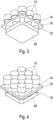
- FIG. 3 and 4 are perspective schematic views of an array of a variety of devices as shown in Fig. 1 or 2 are visible.
- a large number of hollow cylinders 14 are connected to one another via the base element 16.
- a corresponding number of plungers 18 in the embodiment shown are connected to one another via a particularly plate-shaped connecting element 26.
- a significantly larger field of, for example, 10x10, 15x15, 20x20 hollow cylinders and tappets can also be provided.
- a group of, for example, 4, 8 or 16 rams can also be provided, so that a part of the dies is lifted by the rams, filled with material and then the rams are retracted again. The die field and/or the group of rams are then moved.
Landscapes
- Engineering & Computer Science (AREA)
- Mechanical Engineering (AREA)
- Media Introduction/Drainage Providing Device (AREA)
- Moulds For Moulding Plastics Or The Like (AREA)
- Casting Or Compression Moulding Of Plastics Or The Like (AREA)
Description
- Die Erfindung betrifft eine Vorrichtung sowie ein Verfahren zur Herstellung von Mikrostrukturen, insbesondere Mikronadeln.
- Bei den herzustellenden Mikrostrukturen handelt es sich vorzugsweise um Mikronadeln, die insbesondere in ein Mikronadel-Array angeordnet sind. Mikronadeln werden eingesetzt, um Wirkstoffe direkt in die Haut, auch als transdermale Verabreichung bezeichnet, abzugeben. Hierzu weisen die Mikronadeln gerade eine derartige Länge auf, um lediglich in die äußeren Hautschichten einzudringen, jedoch vorzugweise Nerven und Blutgefäße nicht zu erreichen und somit diese unverletzt zu belassen. Nichtsdestotrotz erzeugen Mikronadeln kleine Löcher in den oberen Hautschichten, wodurch die Wirkstoffaufnahme gegenüber einer rein äußerlichen Auftragung von Wirkstoffen auf die Haut signifikant erhöht ist.
- Mikronadel-Arrays, die eine Vielzahl von Mikronadeln, beispielsweise angebracht an einer Trägerfläche, aufweisen, können zur kurzfristigen Verabreichung oder zur langfristigen Applikation verwendet werden. Eine bevorzugte Möglichkeit der Wirkstoffabgabe, von den Mikronadeln in die Haut besteht darin, dass sich wirkstoffaufweisende Bereiche der Mikronadeln oder die gesamte Mikronadel auf- bzw. ablösen und derart über die Haut vom Körper aufgenommen werden. Hierzu sind die Mikronadeln insbesondere, zumindest teilweise, aus wasserlöslichen Stoffen bzw. Materialien hergestellt. Neben der direkten Wirkstoffabgabe durch die Mikronadeln an sich ist es auch möglich, dass die Mikronadeln Poren oder Hohlräume aufweisen oder als Hohlnadeln ausgebildet sind, um derart eine Wirkstoffabgabe an die Haut zu ermöglichen. Darüber hinaus können Mikronadeln an sich auch wirkstofffrei sein. Hierbei kann dann beispielsweise ein äußeres Auftragen des Wirkstoffs auf die Außenseite der Mikronadeln erfolgen oder erst nach dem Entfernen der Mikronadeln von der Haut eine wirkstoffhaltige Substanz auf die entsprechende Hautstelle aufgetragen werden, um derart Wirkstoffe mittels Einsatz von Mikronadeln zu verabreichen.
- Mikronadeln können unter anderem aus Keramik, Metall oder Polymer hergestellt sein. Bevorzugt ist es, dass diesen Materialien eine oder mehrere Wirkstoffkomponenten zugegeben werden und sich derart eine Formulierung der Mikronadeln ergibt.
- Bisher bekannte Verfahren zur Herstellung von therapeutischen oder diagnostischen Mikronadeln bzw. Mikronadel-Arrays eignen sich nicht oder nur eingeschränkt zur Herstellung in ausreichender Qualität und/oder Stückzahl.
- Ein gängiges Verfahren zur Herstellung von Mikronadeln besteht in dem Gießen der Mikronadeln bzw. gesamter Mikronadel-Arrays, beispielsweise mittels Gussform aus Silikon. Insbesondere aufgrund der hydrophoben Eigenschaften zwischen der Gussform und der darauf aufgegebenen, meist flüssigen, Formulierung ergeben sich zahlreiche Probleme bei derartigen Herstellungsverfahren. Insbesondere besteht die Problematik, dass die einzuhaltenden Toleranzen der Mikronadeln äußert gering sind. Entsprechend geringe Toleranzen müssen einerseits bei den Matrizen, das heißt insbesondere Gussformen aus Silikon sichergestellt werden, andererseits müssen auch die Herstellungsprozesse mit entsprechend geringen Toleranzen erfolgen.
- Die Herstellung von Mikronadeln bedingt eine aseptische Prozessierung, da der Wirkstoff offen im Produktionsumfeld verarbeitet werden muss. Eine nachträgliche Sterilisation ist bei vielen Wirkstoffen nicht möglich. Hierdurch besteht die Forderung nach einer aseptischen Herstellung, bei der sterile Einwegprodukte verwendet werden. Durch die Verwendung steriler Einwegprodukte wird das Risiko von Verunreinigungen verhindert.
- Aus
EP 2 090 331 ist eine Vorrichtung sowie ein Verfahren zur Herstellung eines Mikronadel-Arrays bekannt. Hierzu weist eine Form nadelförmige Vertiefungen auf. Zur Herstellung des Mikronadel-Arrays wird Material in die Vertiefungen eingepresst. Anschließend wird die Rückseite mit einer Schicht PMMA verpresst. Auf dessen Oberseite, die von den Nadeln abgewandt ist, wird der Wirkstoff aufgebracht, der in Richtung der Nadeln diffundiert. - Aufgabe der Erfindung ist es, eine Vorrichtung sowie ein Verfahren zur Herstellung von Mikrostrukturen, insbesondere Mikronadeln zu schaffen, mit den Mikrostrukturen mit sehr geringer Toleranzen hergestellt werden können.
- Die Lösung der Aufgabe erfolgt erfindungsgemäß durch eine Vorrichtung gemäß Anspruch 1 bzw. ein Verfahren gemäß Anspruch 11.
- Die erfindungsgemäße Vorrichtung dient insbesondere zur Herstellung von insbesondere sich auflösenden Mikrostrukturen wie Mikronadeln und besonders bevorzugt zur Herstellung von Mikronadel-Arrays. Die Vorrichtung weist eine Matrize auf, die an einer Oberseite mindestens eine, vorzugsweise kegelförmige Vertiefung aufweist. Die Vertiefung dient zur Herstellung der Mikrostruktur, insbesondere im Gussverfahren, das heißt, indem eine meist flüssige Formulierung auf die Oberseite der Matrize, insbesondere dosiert und verteilt wird und diese zur Herstellung der Mikrostruktur aushärtet.
- Ferner weist die Vorrichtung einen Hohlzylinder auf. Dieser ist vorzugsweise Teil eines Basiselements oder bildet ein Basiselement aus. Erfindungsgemäß weist die Matrize ein Halteelement auf bzw. ist mit einem Halteelement verbunden, so dass die Matrize an dem Hohlzylinder befestigt bzw. gehalten werden kann.
- Die Matrize überspannt bzw. überdeckt eine Öffnung des Hohlzylinders. Insbesondere liegt die Matrize in einem Ausgangszustand bzw. in einem Ruhezustand vor dem Verwenden bzw. Befüllen der Matrize mit einer Formulierung an dem Rand der Öffnung des Hohlzylinders an. Bei dem Hohlzylinder handelt es sich insbesondere um einen Zylinder mit kreisförmigem Querschnitt.
- In dem Hohlzylinder ist ein Stößel angeordnet. Dieser ist in Längsrichtung des Hohlzylinders verschiebbar. Insbesondere kann der Stößel ausgehend von einer Ausgangs- oder Ruheposition in eine eingeschobene oder obere Position in den Hohlzylinder eingeschoben werden, so dass eine Oberseite des Stößels an einer Unterseite der Matrize anlegt, wobei die Unterseite der Matrize in Richtung des Inneren des Hohlzylinders weist. Besonders bevorzugt ist es hierbei, dass der Stößel soweit in den Hohlzylinder eingeschoben wird, dass die Matrize den Rand der Öffnung des Hohlzylinders nicht mehr berührt, sondern von diesem abgehoben wird. Hierdurch sind geringen Toleranzen erzielbar. Unabhängig davon, ob die Matrize in der Ausgangs- oder Ruheposition an der Öffnung des Hohlzylinders anliegt, weist die Erfindung den wesentlichen Vorteil auf, dass durch Einschieben des Stößels in den Hohlzylinder derart, dass die Matrize nur noch an der Oberseite des Stößels anliegt, die sich ggf. addierenden Toleranzen reduziert werden können. In der eingeschobenen oder oberen Position ist nur noch die Toleranz der Dicke der Matrize relevant. Toleranzen, die durch den Hohlzylinder hervorgerufen würden, sind hierdurch ausgeschlossen. Dies erlaubt eine mindere Toleranzqualität der Hohlzylinder sowie deren Halteelement, da die Prozesstoleranz über die Stößel hergestellt wird. Durch das Anheben der Matrize wird somit die Toleranzkette unterbrochen und die Toleranz auf die Dicke der Matrize reduziert.
- In besonders bevorzugter Ausführungsform weist das mit der Matrize verbundene Haltelement ein längbares, insbesondere elastisch ausgebildetes Zwischenelement auf. Hierdurch ist es möglich, beim Einschieben des Stößels auf einfache Weise die Matrize von dem Rand der Öffnung des Hohlzylinders abzuheben. Wenn der Stößel zurückgezogen wird, verkürzt sich das Zwischenelement automatisch wieder, so dass die Matrize wieder am Rand der Öffnung des Hohlzylinders anliegt. In dieser Position kann die in die Vertiefung der Matrize eingebrachte Formulierung aushärten.
- Des Weiteren ist es bevorzugt, dass das Halteelement ein Verbindungselement zum Verbinden mit dem Hohlzylinder aufweist. Die Verbindung kann hierbei reibschlüssig erfolgen, wobei eine formschlüssige Verbindung bevorzugt ist.
- Hierzu ist das Verbindungselement vorzugsweise als Rastelement ausgebildet. Das Halteelement weist als Verbindungselement beispielsweise Ansätze auf, die in Ausnehmungen eingreifen, die an dem Hohlzylinder vorgesehen sind. Ebenso kann der Hohlzylinder Ansätze aufweisen, die in entsprechenden Ausnehmungen des Halteelements eingreifen. Hierdurch ist ein lagegenaues Anordnen der Matrize an dem Hohlzylinder möglich. In besonders bevorzugter Ausführungsform werden mit den Hohlzylindern verbundene Matrizen als sterile Einheit verwendet bzw. als sterile Einheit am Produktionsort angeliefert. Nach Herstellung der Mikrostruktur erfolgt vorzugsweise ein Entsorgen dieser Einheit ohne Stößel oder ggf. ein Sterilisieren vor einer erneuten Verwendung.
- In besonders bevorzugter Ausführungsform ist das Zwischenelement mit dem Verbindungselement und mit der Matrize verbunden. Besonders bevorzugt ist es, dass die Matrize und das Zwischenelement und insbesondere die Matrize des Zwischenelements und das Verbindungselements einstückig ausgebildet sind. Als Material ist insbesondere Silikon geeignet. Besonders bevorzugt ist es, dass das Halteelement den Hohlzylinder vorzugsweise in Umfangsrichtung, insbesondere vollständig umgibt. Insbesondere bei einer einstückigen Ausgestaltung der Matrize mit dem Halteelement, gegebenenfalls zusammen mit dem Zwischenelement und dem Verbindungselement ist diese kappenförmig ausgebildet und kann beispielsweise über den Hohlzylinder gestülpt oder in den Hohlzylinder eingesteckt werden.
- In besonders bevorzugter Ausgestaltung umgibt das Halteelement den Hohlzylinder an seiner Außenseite in Umfangsrichtung, insbesondere vollständig oder liegt an einer Innenseite des Hohlzylinders vorzugsweise in Umfangsrichtung vollständig an.
- Bei einer besonders bevorzugten Ausführungsform der Erfindung sind mehrere Hohlzylinder vorgesehen, beispielsweise mit einem gemeinsamen Basiselement verbunden. Die Hohlzylinder sind hier insbesondere in Spalten und Reihen angeordnet und beispielsweise einstückig als Kunststoff-Spritzgusselement hergestellt. Mit jedem einzelnen Hohlzylinder ist eine Matrize verbunden, die wie vorstehend erläutert, insbesondere als Silikonkappe ausgebildet sein kann, die über einen Hohlzylinder gestülpt und/oder in einen Hohlzylinder eingesteckt wird. Des Weiteren ist es bevorzugt, dass mehrere Stößel vorgesehen sind, die insbesondere als Gruppe ebenfalls miteinander verbunden und gemeinsam verschoben werden.
- Hierbei kann die Anzahl der Stößel der Anzahl der Hohlzylinder entsprechen, so dass beim Einschieben sämtliche Stößel in die Hohlzylinder sämtliche Matrizen an der Oberseite der Stößel anliegen und insbesondere vom Rand der einzelnen Hohlzylinder abgehoben werden. Die Gruppe an Stößel kann jedoch auch eine geringere Anzahl als die Anzahl der Hohlzylinder aufweisen, so dass stets eine gruppenweise Herstellung von Mikronadeln erfolgt. Beispielsweise kann eine Gruppe von vier Stößel in die Hohlzylinder eingeschoben werden, so dass die Matrizen entsprechend an der Oberseite des Stößels anliegen und insbesondere vom Rand des Hohlzylinders abgehoben werden. Anschließend erfolgt ein Befüllen der Vertiefungen in den Matrizen durch eine insbesondere von Düsen aufgebrachte Formulierung. Im nächsten Schritt werden die Stößel zurückgezogen, so dass die Matrizen wieder an den Rändern der Hohlzylinder anliegen. Anschließend erfolgt ein Verfahren der Gruppe Stößel und/oder der Gruppe an Hohlzylindern, so dass die Stößel unter einer weiteren Gruppe an Matrizen angeordnet sind und das entsprechende Verfahren wiederholt werden kann.
- Die Erfindung betrifft ferner ein Verfahren zur Herstellung von Mikrostrukturen, insbesondere Mikronadeln und besonders bevorzugt Mikronadel-Arrays. Das Verfahren wird vorzugsweise mit der vorstehend beschriebenen Vorrichtung durchgeführt.
- In einem ersten Schritt erfolgt ein Einschieben des mindestens einen Stößels in den jeweils zugehörigen Hohlzylinder, so dass eine Oberseite des Stößels an einer Unterseite der Matrize anliegt. Abschließend erfolgt ein Befüllen der mindestens einen Vertiefung der Matrize mit einer Formulierung. Als Formulierung ist insbesondere PVP, PLGA, Polymer, Zucker geeignet. Anschließend erfolgt ein Zurückziehen des mindestens einen Stößels und insbesondere nach dem Aushärten ein Entnehmen der Mikrostruktur aus der Matrize.
- Der mindestens eine Stößel wird vorzugsweise derart in den Hohlzylinder eingeschoben, dass die Matrize von dem die Öffnung des Hohlzylinders umgebenden Rand abgehoben wird, um die erzielbaren geringen Toleranzen zu erreichen.
- Vorzugsweise verkürzt sich beim Zurückziehen des mindestens einen Stößels das Zwischenelement des mit der Matrize verbundenen insbesondere einstückig ausgebildeten Zwischenelements des Halteelements derart, dass die Unterseite der Matrize wieder auf dem die Öffnung des Hohlzylinders umgebenden Rand aufliegt. In dieser Position kann die in die mindestens eine Vertiefung eingebrachte Formulierung aushärten.
- Bevorzugt ist es, dass mehrere Matrizen vorhanden sind, die einzeln nacheinander oder in Gruppen befüllt werden, wobei das erfindungsgemäße Verfahren wie vorstehend anhand der Vorrichtung beschrieben vorteilhaft weitergebildet ist.
- Nachfolgend wird die Erfindung anhand einer bevorzugten Ausführungsform unter Bezugnahme auf die anliegenden Zeichnungen näher erläutert.
- Es zeigen:
- Fig. 1
- eine schematische Schnittansicht einer ersten bevorzugten Ausführungsform der Vorrichtung,
- Fig. 2
- eine schematische Schnittansicht einer zweiten bevorzugten Ausführungsform der Vorrichtung, und
- Fig. 3 und 4
- schematische perspektivische Ansichten einer weiteren erfindungsgemäßen Ausführungsform der Vorrichtung, bei der eine Vielzahl von Einzelvorrichtungen wie in den
Fig. 1 oder 2 dargestellt miteinander kombiniert ist. - Die in
Fig. 1 schematisch dargestellte erste bevorzugte Ausführungsform der Erfindung weist eine insbesondere aus einem Silikonmaterial hergestellte Kappe 10 auf, die zu einer Mittellinie 12 rotationssymmetrisch ausgebildet ist. Die Kappe 10 ist auf einem Hohlzylinder 14 angeordnet, der mit einem Basiselement 16 verbunden ist. Der Hohlzylinder 14 ist im dargestellten Ausführungsbeispiel kreiszylindrisch ausgebildet und zur Längsachse 12 rotationssymmetrisch. - Innerhalb des Hohlzylinders 14 ist ein Stößel 18 in Richtungen des Pfeils 20 verschiebbar angeordnet. Der Stößel 18 ist kreiszylindrisch und ebenfalls zur Längsachse rotationssymmetrisch.
- Die Kappe 10 ist im dargestellten Ausführungsbeispiel einstückig ausgebildet und weist eine Matrize 22 auf, an deren Oberseite 24 insbesondere eine Vielzahl von vorzugsweise kegelstumpfförmigen Vertiefungen vorgesehen ist. Hierdurch ist durch Befüllen mit einer Formulierung die Herstellung eines Mikronadel-Arrays möglich. Die Matrize 22 ist im dargestellten Ausführungsbeispiel von einem ringförmigen, den Rand der Matrize versteifenden Versteifungselement 26 umgeben. Dies ist mit einem kreisförmig ausgebildeten Zwischenelement 28 verbunden, durch das eine Verbindung zu einem Halteelement 30 erfolgt. Das Halteelement 30 wird im dargestellten Ausführungsbeispiel durch formschlüssige Verbindungselemente 32, 34 mit einer Außenseite 36 des Hohlzylinders 14 verbunden. Die Verbindungselemente sind als beispielsweise ringförmige Wulst 32 ausgebildet, die an der Außenseite des Hohlzylinders 14 vorgesehen ist und mit einer entsprechenden ringförmigen Ausnehmung 34 entsprechend einer Rastverbindung zusammenwirkt.
- Da die gesamte Kappe 10 im dargestellten Ausführungsbeispiel aus einem Silikonmaterial hergestellt ist und das Zwischenelement 28 eine geringere Wandstärke aufweist, handelt es sich bei dem Zwischenelement 28 um ein längbares, insbesondere elastisch ausgebildetes Zwischenelement. Zwischen dem Zwischenelement 28 und dem Hohlzylinder 14 ist ein Spalt 48 ausgebildet.
- Durch Verschieben des Stößels 18 in
Fig. 1 nach oben, gelangt eine plane Oberseite 38 des Stößels in Anlage mit einer Innenseite 40 der Matrize 22. Hierdurch wird die Matrize 22 von einem Rand 42 des Hohlzylinders, der eine Öffnung 44 des Hohlzylinders umgibt, abgehoben. - Bei einer alternativen Ausführungsform liegt die Innenseite der Matrize 22 nicht an dem Rand 42 des Hohlzylinders an. Dennoch erfolgt durch das Anheben der Matrize 22 durch den Stößel 18 ein unterbrechen der Toleranzkette, sodass nur noch die Toleranz der Dicke der Matrize 22 relevant ist und die Toleranzen des Hohlzylinders 14 nicht mehr berücksichtigt werden müssen, bzw. die Qualität der herzustellenden Mikrostruktur nicht negativ beeinflussen.
- In diesem abgehobenen Zustand der Matrize 22 kann auf die Oberseite der Matrize eine Formulierung, insbesondere durch Aufgespritzt aufgebracht werden, so dass das aufgespritzte Material in die Vertiefungen eindringt. Anschließend erfolgt ein Zurückziehen des Stößels 18, so dass die Innenseite 40 der Matrize 22 wieder am Rand 42 des Hohlzylinders 14 anliegt und in dieser Position aushärten kann.
- Bei der in
Fig. 2 dargestellten alternativen Ausführungsform sind ähnliche oder identische Bauteile mit denselben Bezugszeichen gekennzeichnet. - Der wesentliche Unterschied der beiden in den
Fign. 1 und 2 dargestellten Ausführungsformen besteht darin, dass die Silikonkappe 10 der inFig. 1 dargestellten Ausführungsform den Hohlzylinder 14 umgibt bzw. auf diesen aufgestülpt werden kann und inFig. 2 innerhalb des Hohlzylinders 14 angeordnet ist. Insofern ist insbesondere das Halteelement 30 der Kappe sowie die Verbindungselemente 32, 34 innerhalb des Hohlzylinders 14 angeordnet. Bei dieser Ausführungsform liegt die Matrize 22 nicht an einem Rand des Hohlzylinders 14 an. Im Übrigen ist die Funktion identisch. - In
Fig. 3 und 4 sind perspektivische schematische Ansichten eines Feldes bzw. Arrays von einer Vielzahl von Vorrichtungen dargestellt, wie sie inFig. 1 oder 2 sichtbar sind. Hierbei sind eine Vielzahl von Hohlzylindern 14 über das Basiselement 16 miteinander verbunden. Eine im dargestellten Ausführungsbeispiel entsprechende Anzahl an Stößel 18 ist über ein insbesondere plattenförmiges Verbindungelement 26 miteinander verbunden. An Stelle der schematisch in denFiguren 3 und 4 dargestellten Feldes mit 3x3 Hohlzylindern und Stößeln kann auch ein deutlich größeres Feld von beispielsweise 10x10, 15x15, 20x20 Hohlzylindern und Stößeln vorgesehen sein. - Anstelle des Vorsehens eines Feldes mit einer entsprechenden Anzahl an Stößel 18 kann auch eine Gruppe von beispielsweise 4, 8 oder 16 Stößel vorgesehen sein, so dass jeweils ein Teil der Matrizen durch die Stößel angehoben, mit Material befüllt und anschließend die Stößel wieder zurückgezogen werden. Anschließend erfolgt ein Verfahren des Matrizenfeldes, und/oder der Gruppe an Stößeln.
Claims (15)
- Vorrichtung zur Herstellung von Mikrostrukturen, insbesondere Mikronadeln, miteiner Matrize (22), die an einer Oberseite (24) mindestens eine, vorzugsweise kegelförmige Vertiefung zur Herstellung einer Mikrostruktur aufweist,einem, einen Hohlzylinder (14) aufweisenden Basiselement (16),einem mit der Matrize (22) verbundenen Halteelement (30) zum Halten der Matrize (22) an dem Hohlzylinder (14) derart, dass die Matrize (22) eine Öffnung (44) des Hohlzylinders (14) überspannt undeinem in dem Hohlzylinders (14) angeordneten in Längsrichtung (20) des Hohlzylinders (14) derart verschiebbaren Stößel (18), dass eine Oberseite (38) des Stößels (18) an einer Unterseite (40) der Matrize (22) anliegt.
- Vorrichtung nach Anspruch 1, dadurch gekennzeichnet, dass das Haltelement (30) ein längbares, insbesondere elastisches Zwischenelement (28) aufweist bzw. mit einem Zwischenelement (28) verbunden ist.
- Vorrichtung nach einen der Ansprüche 1 oder 2, dadurch gekennzeichnet, dass das Halteelement (30) ein Verbindungselement (32, 34) zum insbesondere formschlüssigen Verbinden mit dem Hohlzylinder (14) aufweist bzw. mit diesem verbunden ist.
- Vorrichtung nach Anspruch 3, dadurch gekennzeichnet, dass das Zwischenelement (28) mit dem Verbindungselement (32, 34) und der Matrize (22) verbunden ist, insbesondere einstückig ausgebildet ist.
- Vorrichtung nach einen der Ansprüche 1 - 4, dadurch gekennzeichnet, dass das Haltelement (32) vorzugsweise in Umfangsrichtung vollständig den Hohlzylinder (14) umgibt.
- Vorrichtung nach einen der Ansprüche 1 - 4, dadurch gekennzeichnet, dass das Halteelement (32, 34) an einer Innenseite des Hohlzylinders (14) vorzugsweise in Umfangsrichtung vollständig anliegt.
- Vorrichtung nach einen der Ansprüche 3 - 5, dadurch gekennzeichnet, dass zwischen dem Verbindungselement (28) und dem Hohlzylinder (14) ein Spalt (48) ausgebildet ist.
- Vorrichtung nach einen der Ansprüche 1 - 7, dadurch gekennzeichnet, dass der Stößel (18) eine ebene Oberseite (38) aufweist, die in einer eingeschobenen Position an einer Unterseite (40) der Matrize (22) anliegt.
- Vorrichtung nach einen der Ansprüche 1 - 8, dadurch gekennzeichnet, dass das Basiselement (16) mehrere Hohlzylinder (14) aufweist, die vorzugsweise miteinander verbunden sind.
- Vorrichtung nach einen der Ansprüche 1 - 9, dadurch gekennzeichnet, dass mehrere Stößel (18) vorgesehen sind, die vorzugsweise insbesondere über eine Verbindungsplatte (46) miteinander verbunden sind.
- Verfahren zum Herstellen von Mikrostrukturen, insbesondere Mikronadeln, mit einer Vorrichtung nach einem der Ansprüche 1 - 10, mit den Schritten:Einschieben des mindestens einen Stößels (18) in jeweils mindestens einen Hohlzylinder (14), so dass eine Oberseite (38) des mindestens einen Stößels (18) an einer Unterseite (40) der Matrize (22) anliegen, Befüllen der mindestens einen Vertiefung der Matrize (22) mit einer Formulierung,Zurückziehen des Stößels (38) undEntnehmen einer Mikrostruktur, vorzugsweise nach deren Aushärten.
- Verfahren nach Anspruch 11, bei welchen der mindestens eine Stößel (18) derart eingeschoben wird, dass sich das Zwischenelement (28) längt und die Matrize (22) vorzugsweise von einem die Öffnung (44) des Hohlzylinders (14) umgebenden Rand (42) abgehoben wird.
- Verfahren nach Anspruch 11 oder 12, bei welchem sich beim Zurückziehen des mindestens einen Stößels (18) das Zwischenelement (28) kürzt bzw. zusammenzieht, so dass die Unterseite (40) der Matrize (22) auf dem die Öffnung (44) umgebenden Rand (42) des Hohlzylinders (14) anliegt.
- Verfahren nach Anspruch 11 - 13, bei welchem bei Vorhandensein mehrerer Matrizen (22) diese einzeln nacheinander, alle gemeinsam oder in Gruppen mit dem mindestens einen Stößel (38) insbesondere abgehoben werden und anschließend befüllt werden.
- Verfahren nach einen der Ansprüche 11 - 14, dass die mindestens eine Matrize (22) über eine Düseneinrichtung mit einer Formulierung befüllt wird.
Applications Claiming Priority (2)
| Application Number | Priority Date | Filing Date | Title |
|---|---|---|---|
| DE102019122648.1A DE102019122648B4 (de) | 2019-08-22 | 2019-08-22 | Vorrichtung und Verfahren zur Herstellung von Mikrostrukturen |
| PCT/EP2020/073039 WO2021032701A1 (de) | 2019-08-22 | 2020-08-18 | Vorrichtung und verfahren zur herstellung von mikrostrukturen |
Publications (3)
| Publication Number | Publication Date |
|---|---|
| EP4017696A1 EP4017696A1 (de) | 2022-06-29 |
| EP4017696C0 EP4017696C0 (de) | 2025-01-22 |
| EP4017696B1 true EP4017696B1 (de) | 2025-01-22 |
Family
ID=72234811
Family Applications (1)
| Application Number | Title | Priority Date | Filing Date |
|---|---|---|---|
| EP20761166.6A Active EP4017696B1 (de) | 2019-08-22 | 2020-08-18 | Vorrichtung und verfahren zur herstellung von mikrostrukturen |
Country Status (8)
| Country | Link |
|---|---|
| US (1) | US12036705B2 (de) |
| EP (1) | EP4017696B1 (de) |
| JP (1) | JP2022545512A (de) |
| CN (1) | CN114302793A (de) |
| CA (1) | CA3150584A1 (de) |
| DE (1) | DE102019122648B4 (de) |
| ES (1) | ES3015261T3 (de) |
| WO (1) | WO2021032701A1 (de) |
Citations (3)
| Publication number | Priority date | Publication date | Assignee | Title |
|---|---|---|---|---|
| WO2005082596A1 (en) * | 2004-02-23 | 2005-09-09 | 3M Innovative Properties Company | Method of molding for microneedle arrays |
| US20170050010A1 (en) * | 2014-04-24 | 2017-02-23 | Georgia Tech Research Corporation | Microneedles and Methods of Manufacture Thereof |
| WO2020148068A1 (de) * | 2019-01-17 | 2020-07-23 | Lts Lohmann Therapie-Systeme Ag | Träger für mikronadel-array |
Family Cites Families (13)
| Publication number | Priority date | Publication date | Assignee | Title |
|---|---|---|---|---|
| JP3161362B2 (ja) * | 1997-05-01 | 2001-04-25 | 富士ゼロックス株式会社 | 微小構造体、その製造方法、その製造装置、基板および成形型 |
| US6331266B1 (en) * | 1999-09-29 | 2001-12-18 | Becton Dickinson And Company | Process of making a molded device |
| US9302903B2 (en) * | 2000-12-14 | 2016-04-05 | Georgia Tech Research Corporation | Microneedle devices and production thereof |
| ATE468961T1 (de) | 2004-12-07 | 2010-06-15 | 3M Innovative Properties Co | Verfahren zum formen einer mikronadel |
| US20080275400A1 (en) * | 2005-12-23 | 2008-11-06 | Ferguson Dennis E | Manufacturing Microneedle Arrays |
| EP2090331A4 (de) * | 2006-11-22 | 2012-04-18 | Toppan Printing Co Ltd | Mikronadel-anordnung und herstellungsverfahren dafür |
| JP5386193B2 (ja) * | 2008-02-26 | 2014-01-15 | 株式会社半導体エネルギー研究所 | Soi基板の作製方法 |
| JP2011012050A (ja) | 2009-06-03 | 2011-01-20 | Bioserentack Co Ltd | 多孔性基盤を用いたマイクロニードル・アレイとその製造方法 |
| CN102958556B (zh) * | 2010-04-28 | 2017-02-15 | 金伯利-克拉克环球有限公司 | 细胞相互作用增强的纳米图案化医疗装置 |
| JP6207459B2 (ja) * | 2014-05-15 | 2017-10-04 | 富士フイルム株式会社 | 経皮吸収シートの製造方法 |
| JP6499598B2 (ja) * | 2015-10-06 | 2019-04-10 | 富士フイルム株式会社 | 経皮吸収シートの製造方法 |
| KR101697556B1 (ko) * | 2016-08-05 | 2017-01-18 | 이상혁 | 마이크로 구조체 제조장치, 제조방법 및 이로부터 제조된 마이크로 구조체 |
| DE102020109626A1 (de) * | 2020-04-07 | 2021-10-07 | Lts Lohmann Therapie-Systeme Ag | Vorrichtung und Verfahren zur Herstellung eines mehrere Microstrukturen aufweisenden Patches |
-
2019
- 2019-08-22 DE DE102019122648.1A patent/DE102019122648B4/de not_active Expired - Fee Related
-
2020
- 2020-08-18 WO PCT/EP2020/073039 patent/WO2021032701A1/de not_active Ceased
- 2020-08-18 CA CA3150584A patent/CA3150584A1/en active Pending
- 2020-08-18 CN CN202080059406.0A patent/CN114302793A/zh active Pending
- 2020-08-18 US US17/636,996 patent/US12036705B2/en active Active
- 2020-08-18 ES ES20761166T patent/ES3015261T3/es active Active
- 2020-08-18 JP JP2022512436A patent/JP2022545512A/ja active Pending
- 2020-08-18 EP EP20761166.6A patent/EP4017696B1/de active Active
Patent Citations (3)
| Publication number | Priority date | Publication date | Assignee | Title |
|---|---|---|---|---|
| WO2005082596A1 (en) * | 2004-02-23 | 2005-09-09 | 3M Innovative Properties Company | Method of molding for microneedle arrays |
| US20170050010A1 (en) * | 2014-04-24 | 2017-02-23 | Georgia Tech Research Corporation | Microneedles and Methods of Manufacture Thereof |
| WO2020148068A1 (de) * | 2019-01-17 | 2020-07-23 | Lts Lohmann Therapie-Systeme Ag | Träger für mikronadel-array |
Also Published As
| Publication number | Publication date |
|---|---|
| DE102019122648B4 (de) | 2021-04-29 |
| EP4017696C0 (de) | 2025-01-22 |
| JP2022545512A (ja) | 2022-10-27 |
| CA3150584A1 (en) | 2021-02-25 |
| US12036705B2 (en) | 2024-07-16 |
| DE102019122648A1 (de) | 2021-02-25 |
| EP4017696A1 (de) | 2022-06-29 |
| WO2021032701A1 (de) | 2021-02-25 |
| CN114302793A (zh) | 2022-04-08 |
| US20220362973A1 (en) | 2022-11-17 |
| ES3015261T3 (en) | 2025-04-30 |
Similar Documents
| Publication | Publication Date | Title |
|---|---|---|
| DE3789320T2 (de) | Verabreichungsinstrument zum Einführen von festen Medikamenten. | |
| DE19518932C2 (de) | Vorrichtung zur Perforation der Haut für die Vorbereitung einer transdermalen Medikation | |
| EP0779807B1 (de) | VERFAHREN ZU hERSTELLUNG EINER MANTELTABLETTE MIT SPITZEM KERN | |
| DE102006040642A1 (de) | Mikronadeln zur Platzierung in der Haut zwecks transdermaler Applikation von Pharmazeutika | |
| WO1999027986A1 (de) | Verfahren und vorrichtung zur steuerung der eindringtiefe einer injektionsnadel | |
| DE102020104320A1 (de) | Mikronadel-Array, Formkörper zur Herstellung eines Mikronadel-Arrays sowie Verfahren zur Herstellung eines Mikronadel-Arrays | |
| EP3248635A1 (de) | Komponente für eine spritze sowie spritze | |
| EP2089084B1 (de) | Aufsatz für eine spritze oder eine karpule | |
| DE102019122648B4 (de) | Vorrichtung und Verfahren zur Herstellung von Mikrostrukturen | |
| DE102020109626A1 (de) | Vorrichtung und Verfahren zur Herstellung eines mehrere Microstrukturen aufweisenden Patches | |
| EP3893985B1 (de) | Verfahren und vorrichtung zur herstellung von mikronadeln | |
| DE102019200563A1 (de) | Applikator | |
| WO2022167191A1 (de) | Verfahren zur herstellung eines formelements für die herstellung von mikroarrays sowie formelement | |
| EP3795358B1 (de) | Mikronadel und verfahren zur herstellung einer mikronadel | |
| DE102019128888A1 (de) | Verfahren zur Herstellung von Mikrostrukturen | |
| WO2022069141A1 (de) | Verfahren zur herstellung eines formelements für die herstellung von mikroarrays sowie formelement | |
| DE102021118997A1 (de) | Mikronadelarray mit Antiseptika | |
| DE102020104306A1 (de) | Formelement zur Herstellung von Mikrostrukturen | |
| DE112006001487T5 (de) | Polymerer Mikronadelarray und Gerät und Verfahren zur Herstellung desselben | |
| DE102020109157A1 (de) | Trägerelement für Mikronadeln sowie Mikronadelarray-Einrichtung | |
| AT518815B1 (de) | Adapter zur steuerung der hubbewegung eines kolbens einer kolbenspritze | |
| EP4132631A1 (de) | Einrichtung zum herstellen von mikro-arrays sowie verfahren zum herstellen eines mikro-arrays | |
| DE102016117413B4 (de) | Vorrichtung zum Einbringen von Medikamenten in die Vagina | |
| EP4703048A1 (de) | Vorrichtung zur beschichtung von implantaten und zugehöriges verfahren | |
| WO2010000433A2 (de) | Hautpunktierungsstempel |
Legal Events
| Date | Code | Title | Description |
|---|---|---|---|
| STAA | Information on the status of an ep patent application or granted ep patent |
Free format text: STATUS: UNKNOWN |
|
| STAA | Information on the status of an ep patent application or granted ep patent |
Free format text: STATUS: THE INTERNATIONAL PUBLICATION HAS BEEN MADE |
|
| PUAI | Public reference made under article 153(3) epc to a published international application that has entered the european phase |
Free format text: ORIGINAL CODE: 0009012 |
|
| STAA | Information on the status of an ep patent application or granted ep patent |
Free format text: STATUS: REQUEST FOR EXAMINATION WAS MADE |
|
| 17P | Request for examination filed |
Effective date: 20220222 |
|
| AK | Designated contracting states |
Kind code of ref document: A1 Designated state(s): AL AT BE BG CH CY CZ DE DK EE ES FI FR GB GR HR HU IE IS IT LI LT LU LV MC MK MT NL NO PL PT RO RS SE SI SK SM TR |
|
| DAV | Request for validation of the european patent (deleted) | ||
| DAX | Request for extension of the european patent (deleted) | ||
| REG | Reference to a national code |
Ref country code: HK Ref legal event code: DE Ref document number: 40073856 Country of ref document: HK |
|
| GRAP | Despatch of communication of intention to grant a patent |
Free format text: ORIGINAL CODE: EPIDOSNIGR1 |
|
| STAA | Information on the status of an ep patent application or granted ep patent |
Free format text: STATUS: GRANT OF PATENT IS INTENDED |
|
| RIC1 | Information provided on ipc code assigned before grant |
Ipc: B29K 67/00 20060101ALN20240801BHEP Ipc: B29C 59/02 20060101ALN20240801BHEP Ipc: B29L 31/00 20060101ALN20240801BHEP Ipc: A61M 37/00 20060101ALN20240801BHEP Ipc: B29C 33/42 20060101ALI20240801BHEP Ipc: B29C 43/02 20060101ALI20240801BHEP Ipc: B29C 33/40 20060101AFI20240801BHEP |
|
| INTG | Intention to grant announced |
Effective date: 20240816 |
|
| GRAS | Grant fee paid |
Free format text: ORIGINAL CODE: EPIDOSNIGR3 |
|
| GRAA | (expected) grant |
Free format text: ORIGINAL CODE: 0009210 |
|
| STAA | Information on the status of an ep patent application or granted ep patent |
Free format text: STATUS: THE PATENT HAS BEEN GRANTED |
|
| AK | Designated contracting states |
Kind code of ref document: B1 Designated state(s): AL AT BE BG CH CY CZ DE DK EE ES FI FR GB GR HR HU IE IS IT LI LT LU LV MC MK MT NL NO PL PT RO RS SE SI SK SM TR |
|
| REG | Reference to a national code |
Ref country code: GB Ref legal event code: FG4D Free format text: NOT ENGLISH |
|
| REG | Reference to a national code |
Ref country code: CH Ref legal event code: EP |
|
| REG | Reference to a national code |
Ref country code: IE Ref legal event code: FG4D Free format text: LANGUAGE OF EP DOCUMENT: GERMAN |
|
| REG | Reference to a national code |
Ref country code: DE Ref legal event code: R096 Ref document number: 502020010279 Country of ref document: DE |
|
| U01 | Request for unitary effect filed |
Effective date: 20250224 |
|
| U07 | Unitary effect registered |
Designated state(s): AT BE BG DE DK EE FI FR IT LT LU LV MT NL PT RO SE SI Effective date: 20250228 |
|
| REG | Reference to a national code |
Ref country code: ES Ref legal event code: FG2A Ref document number: 3015261 Country of ref document: ES Kind code of ref document: T3 Effective date: 20250430 |
|
| PG25 | Lapsed in a contracting state [announced via postgrant information from national office to epo] |
Ref country code: RS Free format text: LAPSE BECAUSE OF FAILURE TO SUBMIT A TRANSLATION OF THE DESCRIPTION OR TO PAY THE FEE WITHIN THE PRESCRIBED TIME-LIMIT Effective date: 20250422 |
|
| PG25 | Lapsed in a contracting state [announced via postgrant information from national office to epo] |
Ref country code: PL Free format text: LAPSE BECAUSE OF FAILURE TO SUBMIT A TRANSLATION OF THE DESCRIPTION OR TO PAY THE FEE WITHIN THE PRESCRIBED TIME-LIMIT Effective date: 20250122 |
|
| PG25 | Lapsed in a contracting state [announced via postgrant information from national office to epo] |
Ref country code: NO Free format text: LAPSE BECAUSE OF FAILURE TO SUBMIT A TRANSLATION OF THE DESCRIPTION OR TO PAY THE FEE WITHIN THE PRESCRIBED TIME-LIMIT Effective date: 20250422 Ref country code: IS Free format text: LAPSE BECAUSE OF FAILURE TO SUBMIT A TRANSLATION OF THE DESCRIPTION OR TO PAY THE FEE WITHIN THE PRESCRIBED TIME-LIMIT Effective date: 20250522 |
|
| PG25 | Lapsed in a contracting state [announced via postgrant information from national office to epo] |
Ref country code: HR Free format text: LAPSE BECAUSE OF FAILURE TO SUBMIT A TRANSLATION OF THE DESCRIPTION OR TO PAY THE FEE WITHIN THE PRESCRIBED TIME-LIMIT Effective date: 20250122 |
|
| PG25 | Lapsed in a contracting state [announced via postgrant information from national office to epo] |
Ref country code: GR Free format text: LAPSE BECAUSE OF FAILURE TO SUBMIT A TRANSLATION OF THE DESCRIPTION OR TO PAY THE FEE WITHIN THE PRESCRIBED TIME-LIMIT Effective date: 20250423 |
|
| U20 | Renewal fee for the european patent with unitary effect paid |
Year of fee payment: 6 Effective date: 20250827 |
|
| PG25 | Lapsed in a contracting state [announced via postgrant information from national office to epo] |
Ref country code: SM Free format text: LAPSE BECAUSE OF FAILURE TO SUBMIT A TRANSLATION OF THE DESCRIPTION OR TO PAY THE FEE WITHIN THE PRESCRIBED TIME-LIMIT Effective date: 20250122 |
|
| PGFP | Annual fee paid to national office [announced via postgrant information from national office to epo] |
Ref country code: ES Payment date: 20250926 Year of fee payment: 6 |
|
| PGFP | Annual fee paid to national office [announced via postgrant information from national office to epo] |
Ref country code: GB Payment date: 20250820 Year of fee payment: 6 |
|
| PGFP | Annual fee paid to national office [announced via postgrant information from national office to epo] |
Ref country code: CH Payment date: 20250901 Year of fee payment: 6 |
|
| PG25 | Lapsed in a contracting state [announced via postgrant information from national office to epo] |
Ref country code: CZ Free format text: LAPSE BECAUSE OF FAILURE TO SUBMIT A TRANSLATION OF THE DESCRIPTION OR TO PAY THE FEE WITHIN THE PRESCRIBED TIME-LIMIT Effective date: 20250122 |
|
| PG25 | Lapsed in a contracting state [announced via postgrant information from national office to epo] |
Ref country code: SK Free format text: LAPSE BECAUSE OF FAILURE TO SUBMIT A TRANSLATION OF THE DESCRIPTION OR TO PAY THE FEE WITHIN THE PRESCRIBED TIME-LIMIT Effective date: 20250122 |
|
| PLBE | No opposition filed within time limit |
Free format text: ORIGINAL CODE: 0009261 |
|
| STAA | Information on the status of an ep patent application or granted ep patent |
Free format text: STATUS: NO OPPOSITION FILED WITHIN TIME LIMIT |
|
| 26N | No opposition filed |
Effective date: 20251023 |
|
| PG25 | Lapsed in a contracting state [announced via postgrant information from national office to epo] |
Ref country code: MC Free format text: LAPSE BECAUSE OF FAILURE TO SUBMIT A TRANSLATION OF THE DESCRIPTION OR TO PAY THE FEE WITHIN THE PRESCRIBED TIME-LIMIT Effective date: 20250122 |
|
| PG25 | Lapsed in a contracting state [announced via postgrant information from national office to epo] |
Ref country code: IE Free format text: LAPSE BECAUSE OF NON-PAYMENT OF DUE FEES Effective date: 20250818 |