EP4016758B1 - Spuradapter und antriebsstromversorgung und spurlicht davon - Google Patents
Spuradapter und antriebsstromversorgung und spurlicht davon Download PDFInfo
- Publication number
- EP4016758B1 EP4016758B1 EP21183159.9A EP21183159A EP4016758B1 EP 4016758 B1 EP4016758 B1 EP 4016758B1 EP 21183159 A EP21183159 A EP 21183159A EP 4016758 B1 EP4016758 B1 EP 4016758B1
- Authority
- EP
- European Patent Office
- Prior art keywords
- power supply
- track
- conductive
- positive electrode
- adjustment
- Prior art date
- Legal status (The legal status is an assumption and is not a legal conclusion. Google has not performed a legal analysis and makes no representation as to the accuracy of the status listed.)
- Active
Links
Images


Classifications
-
- F—MECHANICAL ENGINEERING; LIGHTING; HEATING; WEAPONS; BLASTING
- F21—LIGHTING
- F21V—FUNCTIONAL FEATURES OR DETAILS OF LIGHTING DEVICES OR SYSTEMS THEREOF; STRUCTURAL COMBINATIONS OF LIGHTING DEVICES WITH OTHER ARTICLES, NOT OTHERWISE PROVIDED FOR
- F21V21/00—Supporting, suspending, or attaching arrangements for lighting devices; Hand grips
- F21V21/34—Supporting elements displaceable along a guiding element
- F21V21/35—Supporting elements displaceable along a guiding element with direct electrical contact between the supporting element and electric conductors running along the guiding element
-
- F—MECHANICAL ENGINEERING; LIGHTING; HEATING; WEAPONS; BLASTING
- F21—LIGHTING
- F21V—FUNCTIONAL FEATURES OR DETAILS OF LIGHTING DEVICES OR SYSTEMS THEREOF; STRUCTURAL COMBINATIONS OF LIGHTING DEVICES WITH OTHER ARTICLES, NOT OTHERWISE PROVIDED FOR
- F21V21/00—Supporting, suspending, or attaching arrangements for lighting devices; Hand grips
- F21V21/02—Wall, ceiling, or floor bases; Fixing pendants or arms to the bases
- F21V21/025—Elongated bases having a U-shaped cross section
-
- F—MECHANICAL ENGINEERING; LIGHTING; HEATING; WEAPONS; BLASTING
- F21—LIGHTING
- F21V—FUNCTIONAL FEATURES OR DETAILS OF LIGHTING DEVICES OR SYSTEMS THEREOF; STRUCTURAL COMBINATIONS OF LIGHTING DEVICES WITH OTHER ARTICLES, NOT OTHERWISE PROVIDED FOR
- F21V23/00—Arrangement of electric circuit elements in or on lighting devices
- F21V23/003—Arrangement of electric circuit elements in or on lighting devices the elements being electronics drivers or controllers for operating the light source, e.g. for a LED array
- F21V23/004—Arrangement of electric circuit elements in or on lighting devices the elements being electronics drivers or controllers for operating the light source, e.g. for a LED array arranged on a substrate, e.g. a printed circuit board
- F21V23/006—Arrangement of electric circuit elements in or on lighting devices the elements being electronics drivers or controllers for operating the light source, e.g. for a LED array arranged on a substrate, e.g. a printed circuit board the substrate being distinct from the light source holder
-
- F—MECHANICAL ENGINEERING; LIGHTING; HEATING; WEAPONS; BLASTING
- F21—LIGHTING
- F21V—FUNCTIONAL FEATURES OR DETAILS OF LIGHTING DEVICES OR SYSTEMS THEREOF; STRUCTURAL COMBINATIONS OF LIGHTING DEVICES WITH OTHER ARTICLES, NOT OTHERWISE PROVIDED FOR
- F21V23/00—Arrangement of electric circuit elements in or on lighting devices
- F21V23/003—Arrangement of electric circuit elements in or on lighting devices the elements being electronics drivers or controllers for operating the light source, e.g. for a LED array
- F21V23/007—Arrangement of electric circuit elements in or on lighting devices the elements being electronics drivers or controllers for operating the light source, e.g. for a LED array enclosed in a casing
- F21V23/009—Arrangement of electric circuit elements in or on lighting devices the elements being electronics drivers or controllers for operating the light source, e.g. for a LED array enclosed in a casing the casing being inside the housing of the lighting device
-
- F—MECHANICAL ENGINEERING; LIGHTING; HEATING; WEAPONS; BLASTING
- F21—LIGHTING
- F21V—FUNCTIONAL FEATURES OR DETAILS OF LIGHTING DEVICES OR SYSTEMS THEREOF; STRUCTURAL COMBINATIONS OF LIGHTING DEVICES WITH OTHER ARTICLES, NOT OTHERWISE PROVIDED FOR
- F21V23/00—Arrangement of electric circuit elements in or on lighting devices
- F21V23/02—Arrangement of electric circuit elements in or on lighting devices the elements being transformers, impedances or power supply units, e.g. a transformer with a rectifier
- F21V23/023—Power supplies in a casing
-
- H—ELECTRICITY
- H01—ELECTRIC ELEMENTS
- H01R—ELECTRICALLY-CONDUCTIVE CONNECTIONS; STRUCTURAL ASSOCIATIONS OF A PLURALITY OF MUTUALLY-INSULATED ELECTRICAL CONNECTING ELEMENTS; COUPLING DEVICES; CURRENT COLLECTORS
- H01R13/00—Details of coupling devices of the kinds covered by groups H01R12/70 or H01R24/00 - H01R33/00
- H01R13/66—Structural association with built-in electrical component
- H01R13/70—Structural association with built-in electrical component with built-in switch
- H01R13/71—Contact members of coupling parts operating as switch, e.g. linear or rotational movement required after mechanical engagement of coupling part to establish electrical connection
-
- H—ELECTRICITY
- H01—ELECTRIC ELEMENTS
- H01R—ELECTRICALLY-CONDUCTIVE CONNECTIONS; STRUCTURAL ASSOCIATIONS OF A PLURALITY OF MUTUALLY-INSULATED ELECTRICAL CONNECTING ELEMENTS; COUPLING DEVICES; CURRENT COLLECTORS
- H01R25/00—Coupling parts adapted for simultaneous co-operation with two or more identical counterparts, e.g. for distributing energy to two or more circuits
- H01R25/14—Rails or bus-bars constructed so that the counterparts can be connected thereto at any point along their length
- H01R25/142—Their counterparts
-
- H—ELECTRICITY
- H01—ELECTRIC ELEMENTS
- H01R—ELECTRICALLY-CONDUCTIVE CONNECTIONS; STRUCTURAL ASSOCIATIONS OF A PLURALITY OF MUTUALLY-INSULATED ELECTRICAL CONNECTING ELEMENTS; COUPLING DEVICES; CURRENT COLLECTORS
- H01R25/00—Coupling parts adapted for simultaneous co-operation with two or more identical counterparts, e.g. for distributing energy to two or more circuits
- H01R25/14—Rails or bus-bars constructed so that the counterparts can be connected thereto at any point along their length
- H01R25/145—Details, e.g. end pieces or joints
-
- H—ELECTRICITY
- H01—ELECTRIC ELEMENTS
- H01R—ELECTRICALLY-CONDUCTIVE CONNECTIONS; STRUCTURAL ASSOCIATIONS OF A PLURALITY OF MUTUALLY-INSULATED ELECTRICAL CONNECTING ELEMENTS; COUPLING DEVICES; CURRENT COLLECTORS
- H01R24/00—Two-part coupling devices, or either of their cooperating parts, characterised by their overall structure
- H01R24/38—Two-part coupling devices, or either of their cooperating parts, characterised by their overall structure having concentrically or coaxially arranged contacts
Definitions
- the present invention relates to a track adapter.
- a track light is a lamp mounted on a track, and the track adapter thereof is mounted in a matching track used for power supply.
- There are conductive metal strips on both sides within the track and a conventional track adapter may be provided with rotatable conductive metal sheets. The conductive metal sheets on the track light contact the conductive metal strips within the track when mounted, so that the track light can be energized, that is, the track light can be light.
- phase adjustment portion In order to realize a track light with different power supply modes and multiple lines and circuits, it is necessary to provide a plurality of conductive metal sheets and set a phase adjustment portion to adjust the electrical conduction between the conductive metal sheet and the track light to make the track light and enable different conductive metal strips within the track. The output of the phase adjustment portion is then connected to the driving power supply to supply power to the track light.
- phase adjustment portion of a traditional track adapter is placed at the bottom of the adapter. After it has been installed to a track, some parts are exposed to the outside of the track, which is not beautiful in appearance and increases the cost.
- CN 211 146 219 U discloses a track adapter according to the preamble of claim 1, with basically the same configuration and function of the electrical supply column. However, the electrical supply column is rotated by means of the operating lever.
- a drive mechanism comprising two inter-meshing gears, which is operated by means of an adjustment knob fixedly connected to the second drive gear and provided on the top or even outside of the track adapter is not disclosed.
- WO 2019/167202 A1 and EP 3 567 312 A1 of the same applicant each discloses a drive mechanism with drive gears.
- the electrical supply column is, however, rotated by means of an operating lever disposed at the side of the track adapter, but not at the top end of the track adapter.
- the lamp holder of the track lamp can wrap the whole track, which is neat and beautiful, and solves the problem of difficult phase adjustment of the adaptor in the prior art at the same time.
- the phase adjustment knob is shrunk (of reduced size) and provided on the top of the adapter, which solves the afore-mentioned adjustment problem and adapts to more occasions, so that the structural design of the track lamp can be more flexible.
- the track adapter 1000 of the present invention can be used alone or can be integrated with a driving power supply, as long as the housing of the driving power supply is defined as the mounting seat 100 in the sense of the present invention for fixing and mounting other components of the track adapter 1000, and the remaining structure is unchanged.
- the track adapter 1000 is used alone, it is connected to a light fixture or to the positive and negative poles of a separate driving power supply.
- the embodiment that will be described hereinafter is illustrated with integration as an example.
- the driving power supply 2000 of the present embodiment includes a power supply housing 2001 and a circuit board 2002 and a track adapter 1000 disposed in the power supply housing.
- the track adapter 1000 can be used alone and independently with the power supply housing 2001 and the circuit board 2002 removed.
- the track adapter 1000 of the present embodiment includes a mounting seat 100, an electrical supply column (power take-off post) 200, an adjustment conductive portion 300, an adjustment knob 400, and a drive mechanism 500.
- the mounting seat 100 is used to carry other components, and the mounting seat 100 may be the power supply housing 2001 itself or a component manufactured for manufacturing and mounting.
- the mounting seat 100 includes a power supply housing 2001 and a mounting piece 103 fixed to the power supply housing 2001.
- the mounting seat 100 has a first central axis 101, and the electrical supply column 200 can be rotated about the first central axis 101 and is arranged on the mounting seat 100.
- the electrical supply column 200 has a general structure and configuration that is matched with the track, and it can be inserted into the track groove to implement the electric connection after rotation.
- the electrical supply column 200 is provided with a negative electrode conductive sheet 201 and at least two positive electrode conductive sheets 202.
- the negative electrode and positive electrode are defined as: L and N as the symbols in alternating current, where L is the "fire line” of single-phase alternating current, that is the positive pole, N is the "zero line” of single-phase alternating current, that is the negative pole, and in direct current, "+" represents the positive electrode and "-" represents the negative electrode.
- a multi-wire track of the prior art such as with four wire tracks, which is a standard part, it is generally of U-shaped profile and a plurality of card slots extending on both sides of the U-shaped profile is provided for arranging conductive metal strips L1, conductive metal strip L2, the conductive metal strip L3, and the conductive metal strip N.
- the conductive metal strips can be arranged on a separate side.
- There are also other schemes such as the conductive metal strips in different quantities are set on both sides, which is known from the prior art and will not be described hereinafter in more detail.
- the negative electrode conductive sheet 201 and the positive electrode conductive sheet 202 on the electrical supply column 200 can be set correspondingly.
- the electrical supply column 200 is extended into the track and rotated to realize the connection and conduction of the negative electrode conductive sheet 201 and the positive electrode conductive sheet 202 with the corresponding conductive metal strip.
- the negative electrode conductive sheet 201 needs to be in permanent electrical contact, and it is necessary to choose one of the positive electrode conductive sheet 202 to conduct, the specific mode being as follows: the positive electrode conductive sheet 202 extends to the bottom of the electrical supply column 200 forming a positive electrode contact 2021, and the positive electrode contacts 2021 are arranged around the first central axis 101 at intervals.
- the adjustment conductive portion 300 is located at the bottom of the electrical supply column 200, and is rotated around the first central axis 101 and arranged on the mounting seat 100, and is provided with a conductive contact 301 in flexible connection with the bottom of the electrical supply column 200.
- the moving path of the conductive contact 301 passes through (all of) the positive electrode contacts 2021.
- the conductive contact 301 When the electrical supply column 200 is rotated to be connected to the track, the conductive contact 301 is in electric contact with one of the positive contacts 2021, that is, it conducts with the corresponding conductive metal strip.
- the flexible connection may be accomplished by abutment or a combination of a plug-in and an annular groove.
- the adjustment knob 400 In order to make the conductive contact 301 conductive with different positive electrode contacts 2021, the adjustment knob 400 is rotated and arranged on the mounting seat 100 and located on the outside of the top of the electrical supply column 200.
- the drive mechanism 500 is used to implement (drive) the connection between the adjustment knob 400 and the adjustment conductive portion 300.
- the drive mechanism 500 By turning the adjustment knob 400, the drive mechanism 500 will transmit the stroke of the adjustment knob 400 to the adjustment conductive portion 300, and the adjustment conductive portion 300 will be adjusted (displaced) to rotate to the designed position, when the electrical supply column 200 is rotated in place, it will conduct with the required conductive metal strip.
- the adjustment knob 400 of the present embodiment is arranged on the outside of the top of the electrical supply column 200 facilitating manual adjustment, particularly when the track adapter 1000 is installed in a deep and narrow structure.
- the adjustment conductive portion 300 may further include a positive electrode conductive connector 304 and a negative electrode conductive connector 305 which are fixedly arranged.
- the positive electrode conductive connector 304 maintains a constant (permanent) electrical conduction with the conductive contact 301.
- the positive electrode conductive connector 304 maintains a constant conduction with the conductive contact 301 through a conductive ring.
- the negative electrode conductive connector 305 is in conduction with the negative electrode conductive sheet 201.
- the drive mechanism 500 is realized in many forms, such as thread drive, gear transmission, rack transmission, etc.
- the mounting seat 100 is provided with a second central axis 102 parallel to the first central axis 101.
- the drive mechanism 500 includes a first drive gear 501 and a second drive gear 502.
- the first drive gear 501 is located at the bottom of the electrical supply column 200 and fixedly connected to the adjustment conductive portion 300, and its gear shaft is coincidence with the first central axis 101;
- the second drive gear 502 is engaged with the first drive gear 501 and is rotatable around the second central axis 102 and arranged on the mounting seat 100.
- the adjustment knob 400 is fixed to the second drive gear 502, and the mounting piece 103 are provided with two mounting holes for arranging the first drive gear 501 and the second drive gear 502, where rotational connection is realized through buckle structure.
- the bottom of the electrical supply column 200 is radially expanded to form a conductive plate 203.
- the positive electrode contact 2021 is a sheet attached to the bottom surface of the conductive plate 203, and the conductive contact 301 abuts against the bottom surface of the conductive plate 203.
- the large contact area of the sheet structure can assist in avoiding the conventional connection instability caused by manufacturing and assembly errors.
- the negative electrode conductive sheet 201 is different from the positive electrode conductive sheet 202, and it does not need to choose. It only needs to wait for the electrical supply column 200 to be rotated in place. In order to facilitate integral production, the negative electrode conductive sheet 201 may extend to the bottom of the electrical supply column 200 to form a negative electrode contact 2011. In the present embodiment, the negative electrode contacts 2011 and the positive electrode contact 2021 are arranged on the same surface and arranged together.
- the structure of the adjustment conductive portion 300 is fitting with the bottom of the electrical supply column 200.
- the adjustment conductive portion 300 includes an adjustment plate 302 and an annular conductive plate 303.
- the adjustment plate 302 is provided with a shaft hole 3021 in the middle, and the plate surface of the adjustment plate 302 faces against (toward) the positive electrode contact 2021 on the bottom surface of the conductive plate 203 and a through hole 3022 is provided on the plate surface.
- the middle of the bottom surface of the conductive plate 203 is provided with a rotating shaft 2031 that cooperates with the shaft hole 3021.
- Tthe annular conductive plate 303 is arranged on the bottom surface of the adjustment plate 302, being with a conductive shrapnel passing through the through hole 3022 as the conductive contact 301 thereon.
- This embodiment is used to cooperate with the common standard parts of a four-wire track.
- the electrical supply column 200 may be provided with a protruding rotating handle 204.
- the above-described track adapter 1000 can be produced independently, manufactured, and mounted. In this embodiment it is integrated into the driving power supply. More specifically, the mounting seat 100 is fixed to the power supply housing 2001, and the power supply housing 2001 has a left portion 2007 and a right portion 2008.
- the positive electrode conductive connector 304 is connected to the positive input end of the circuit board 2002
- the negative electrode conductive connector 305 is connected to the negative input end of the circuit board 2002
- the connection method is inserted or welded.
- the mounting seat 100, the adjustment column 200, the adjustment conductive portion 300 and the drive mechanism 500 are disposed in the power supply housing 2001.
- the top of the power supply housing 2001 is provided with a mounting hole for the adjustment knob 400 passing through, and at least one side of the power supply housing 2001 is provided with an electrical supply hole 2004 that is provided for the negative electrode conductive sheet 201 and the positive electrode conductive sheet 202 passing through.
- the power supply housing 2001 is provided with an electrical supply hole 2004 on both sides.
- the track adapter 1000 of this embodiment is particularly useful for a track light of the present embodiment as described in the following.
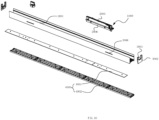
- the track light includes a lamp holder 3000.
- the lamp holder 3000 is provided with a light source assembly 4000, a driving power supply 2000, and a track adapter 1000.
- the lamp holder driving power supply includes a power supply housing 2001 and a circuit board 2002 disposed in the power supply housing, the mounting seat 100 is fixed to the power supply housing 2001, the positive electrode conductive connector 304 is connected to the positive input end of the circuit board 2002, and the negative electrode conductive connector 305 is connected to the negative input end of the circuit board 2002.
- the lamp holder of the present embodiment may wrap the whole track, and its design is neat and beautiful.
- the lamp holder 3000 includes a U-shaped profile 3001 with opening upward and an end cover 3002 provided at both ends of the U-shaped profile 3001.
- the light source assembly 4000 is arranged on the outer side of the U-shaped profile 3001, the track adapter 1000 is arranged in the bottom of the U-shaped profile 3001, and the end cover 3002 is provided with a notch 3003 that avoids the track.
- the U-shaped profile 3001 extends downward on both sides.
- the light source assembly 4000 includes a lamp plate 4001 and an optical element 4002.
- the power supply housing 2001 includes a lower portion 2006 and an upper portion 2005 inserted (in particular snapped) into the track.
- the mounting seat 100, a electrical supply column 200, and the adjustment conductive portion 300 and the drive mechanism 500 are disposed in the power supply housing 2001.
- the top of the upper portion 2005 is provided with a mounting hole 2003 for the adjustment knob 400 to be exposed, and both sides are provided with an electrical supply hole 2004 for the negative electrode conductive sheet 201 and the positive electrode conductive sheet 202, respectively, to pass through.
- the upper portion 2005 is stuck in the track, and therefore the width of the lower portion 2006 is larger than the upper portion 2005, for facilitating the drive mechanism 500 to accommodate the mounting seat 100 and the drive mechanism 500.
- the electrical supply column 200 is provided with a rotating handle 204 extending out of the power supply housing 2001, and the side wall of the U-shaped profile 3001 is provided with a strip hole 3006 where the rotating handle 204 passes through.
Landscapes
- Engineering & Computer Science (AREA)
- General Engineering & Computer Science (AREA)
- Power Engineering (AREA)
- Microelectronics & Electronic Packaging (AREA)
- Arrangement Of Elements, Cooling, Sealing, Or The Like Of Lighting Devices (AREA)
- Fastening Of Light Sources Or Lamp Holders (AREA)
Claims (14)
- Stromschienenadapter (1000), umfassend:einen Befestigungsträger (100) mit einer ersten Mittelachse (101), die sich zwischen einer Oberseite und einer Unterseite des Befestigungsträgeres (100) erstreckt;eine Stromversorgungssäule (200), die auf dem Befestigungsträger (100) angeordnet ist, wobei die Stromversorgungssäule (200) eine Oberseite, die an der Oberseite des Befestigungsträgeres (100) angeordnet ist, und eine Unterseite aufweist, die an der Unterseite des Befestigungsträgeres (100) angeordnet ist, wobei sich die Stromversorgungssäule (200) entlang der ersten Mittelachse (101) erstreckt und um die erste Mittelachse (101) drehbar ist, wobei die Stromversorgungssäule (200) mit einer negativen Elektrodenleitblech (201) und mindestens zwei positiven Elektrodenleitblechen (202) an ihrem Säulenkörper versehen ist, jedes positive Elektrodenleitblech (202) sich zum Boden der Stromversorgungssäule (200) erstreckt, um einen positiven Elektrodenkontakt (2021) auszubilden, das negative Elektrodenleitblech (201) sich zum Boden der Stromversorgungssäule (200) erstreckt, um einen negativen Elektrodenkontakt (2011) auszubilden, und die positiven Elektrodenkontakte (2021) in Abständen um die erste Mittelachse (101) herum angeordnet sind;einen leitenden Verstellabschnitt (300), der sich am Boden der Stromversorgungssäule (200) befindet, um die erste Mittelachse (101) drehbar ist und auf dem Befestigungsträger (100) angeordnet ist, wobei der leitende Verstellabschnitt (300) mit einem leitenden Kontakt (301) in flexibler Verbindung mit dem Boden der Stromversorgungssäule (200) versehen ist, wobei ein Verstellweg des leitenden Kontakts (301) durch die positiven Elektrodenkontakte (2021) verläuft;
undeinen Antriebsmechanismus (500), der zum Antreiben einer Drehung der Stromversorgungssäule (200) um die erste Mittelachse (101) ausgelegt ist; wobeider leitende Verstellabschnitt (300) umfassteinen leitenden Verbinder (304) für die positive Elektrode, der so konfiguriert ist, dass er über einen der positiven Elektrodenkontakte (2021) eine elektrische Verbindung mit jeder der mindestens zwei positiven Elektrodenleitbleche (202) herstellt; undeinen leitenden Verbinder (305) für die negative Elektrode, der so konfiguriert ist, dass er über den negativen Elektrodenkontakt (2011) eine elektrische Verbindung mit dem negativen Elektrodenleitblech (201) herstellt, wenn das negative Elektrodenleitblech (201) in eine Verbindungsposition gedreht wird;dadurch gekennzeichnet, dassder Antriebsmechanismus (500) umfasst:ein erstes Antriebszahnrad (501), das sich am Boden der Stromversorgungssäule (200) befindet und mit dem leitenden Verstellabschnitt (300) verbunden ist, wobei seine Zahnradwelle mit der ersten Mittelachse (101) zusammenfällt; undein zweites Antriebszahnrad (502), das mit dem ersten Antriebszahnrad (501) in Eingriff steht, um eine zweite, parallel zur ersten Mittelachse (101) verlaufende Mittelachse (102) drehbar ist und auf dem Befestigungsträger (100) angeordnet ist; wobeider Stromschienenadapter (1000) eine Längsachse definiert, die senkrecht zu der ersten und zweiten Mittelachse (101, 102) verläuft,das erste und das zweite Antriebszahnrad (501, 502) entlang der Längsachse des Raupenadapters (1000) voneinander beabstandet angeordnet sind, undein Verstellknopf (400) fest mit dem zweiten Antriebszahnrad (502) verbunden ist, um drehbar auf dem Befestigungsträger (100) angeordnet zu sein, so dass der Verstellknopf (400) auf der Außenseite der Oberseite der Stromversorgungssäule (200) angeordnet ist und der Antriebsmechanismus (500) eine Antriebsverbindung zwischen dem Verstellknopf (400) und dem leitenden Verstellabschnitt (300) herstellt. - Stromschienenadapter (1000) nach Anspruch 1, wobei die Unterseite der Stromversorgungssäule (200) radial erweitert ist, um eine leitende Platte (203) auszubilden, wobei jeder positive Elektrodenkontakt (2021) die Form eines Blechs hat, das an einer Unterseite der leitenden Platte (203) befestigt ist, und der leitende Kontakt (301) an der Unterseite der leitenden Platte (203) anliegt.
- Stromschienenadapter (1000) nach Anspruch 2, wobei der leitende Verstellabschnitt (300) umfasst:eine Einstellplatte (302), die mit einem Wellenloch (3021) in der Mitte versehen ist, wobei eine Plattenfläche der Einstellplatte (302) den positiven Elektrodenkontakten (2021) auf der Bodenfläche der leitenden Platte (203) gegenüberliegt und ein Durchgangsloch (3022) auf der Plattenfläche vorgesehen ist, und wobei eine Drehwelle (2031) in der Mitte der Bodenfläche der leitenden Platte (203) vorgesehen ist, die mit dem Wellenloch (3021) zusammenwirkt;und eine ringförmige leitende Platte (303), die auf der Unterseite der Einstellplatte (302) angeordnet ist, wobei sich ein leitendes Stückchen durch das Durchgangsloch (3022) als der darauf ausgebildete leitende Kontakt (301) erstreckt.
- Stromschienenadapter (1000) nach einem der vorhergehenden Ansprüche, wobei drei positive Elektrodenleitbleche (202) vorgesehen sind.
- Stromschienenadapter (1000) nach einem der vorangehenden Ansprüche, wobei die Stromversorgungssäule (200) mit einem vorstehenden Drehgriff (204) versehen ist.
- Spannungsversorgung (2000) mit einem Stromversorgungsgehäuse (2001) und einer in dem Stromversorgungsgehäuse angeordneten Leiterplatte (2002),gekennzeichnet durch den Stromschienenadapter (1000) nach einem der vorhergehenden Ansprüche, wobeider Befestigungsträger (100) an dem Stromversorgungsgehäuse (2001) befestigt ist,der leitende Verbinder (304) für die positive Elektrode mit einem positiven Eingangsende der Leiterplatte (2002) verbunden ist, undder leitende Verbinder (305) für die negative Elektrode mit einem negativen Eingangsende der Leiterplatte (2002) verbunden ist.
- Spannungsversorgung (2000) nach Anspruch 6, wobeider Befestigungsträger (100), die Stromversorgungssäule (200), der leitende Verstellabschnitt (300) und der Antriebsmechanismus (500) in dem Stromversorgungsgehäuse (2001) angeordnet sind,eine Oberseite des Stromversorgungsgehäuses (2001) mit einem Montageloch versehen ist, durch das sich der Verstellknopf (400) hindurch erstreckt, undmindestens eine Seite des Stromversorgungsgehäuses (2001) mit einem Stromversorgungsloch (2004) versehen ist, das für das Durchführen des negativen Elektrodenleitblechs (201) und des positiven Elektrodenleitblechs (202) vorgesehen ist.
- Spannungsversorgung (2000) nach Anspruch 6 oder 7, wobeidrei positive Elektrodenleitbleche (202) vorhanden sind, die paarweise mit dem negativen Elektrodenleitblech (201) gruppiert und auf beiden Seiten der Spannungsversorgungssäule (200) herum angeordnet sind, unddas Stromversorgungsgehäuse (2001) auf beiden Seiten mit einem Stromversorgungsloch (2004) versehen ist.
- Stromschienenleuchte mit einer Lampenhalterung (3000), die eine Lichtquellenanordnung (4000), eine Spannungsversorgung (2000) und den Stromschienenadapter (1000) nach einem der Ansprüche 1 bis 5 umfasst, die an der Lampenhalterung (3000) angeordnet sind.
- Stromschienenleuchte nach Anspruch 9, wobeidie Spannungsversorgung der Lampenhalterung ein Stromversorgungsgehäuse (2001) und eine in dem Stromversorgungsgehäuse angeordnete Leiterplatte (2002) umfasst,der Befestigungsträger (100) an dem Stromversorgungsgehäuse (2001) befestigt ist,der leitende Verbinder (304) für die positive Elektrode mit dem positiven Eingangsende der Leiterplatte (2002) verbunden ist, undder leitende Verbinder (305) für die negative Elektrode mit dem negativen Eingangsende der Leiterplatte (2002) verbunden ist.
- Stromschienenleuchte nach Anspruch 9 oder 10, wobeidie Lampenhalterung (3000) ein U-förmiges Profil (3001) mit einer nach oben gerichteten Öffnung und eine Endabdeckung (3002) an beiden Enden des U-förmigen Profils (3001) aufweist,
unddie Lichtquellenanordnung (4000) an der Außenseite des U-förmigen Profils (3001) angeordnet ist, wobei der Stromschienenadapter (1000) im Boden des U-förmigen Profils (3001) angeordnet ist;
unddie Endabdeckung (3002) mit einer Kerbe (3003) versehen ist, um die Schiene zu umgehen. - Stromschienenleuchte nach Anspruch 9, wobeidas Stromversorgungsgehäuse (2001) einen unteren Abschnitt (2006) und einen oberen Abschnitt (2005) aufweist, die in die Stromschiene eingesetzt sind,der Befestigungsträger (100), die Stromversorgungssäule (200), der leitende Verstellabschnitt (300) und der Antriebsmechanismus (500) in dem Stromversorgungsgehäuse (2001) angeordnet sind,die Oberseite des oberen Abschnitts (2005) mit einem Montageloch (2003) versehen ist, so dass der Verstellknopf (400) freiliegt, unddie beiden Seiten mit dem Stromversorgungsloch (2004) versehen sind, das für den Durchgang des negativen Elektrodenleitblechs (201) und des positiven Elektrodenleitblechs (202) vorgesehen ist.
- Stromschienenleuchte nach Anspruch 12, wobei die Breite des unteren Abschnitts (2006) größer ist als die Breite des oberen Abschnitts (2005), sodass der Antriebsmechanismus (500) den Befestigungsträgere (100) und den Antriebsmechanismus (500) leichter aufnehmen kann.
- Schienenleuchte nach einem der Ansprüche 9 bis 13, wobeidie Stromversorgungssäule (200) mit einem Drehgriff (204) versehen ist, der aus dem Stromversorgungsgehäuse (2001) herausragt, unddie Seitenwand des U-förmigen Profils (3001) mit einer streifenförmigen Nut (3006) versehen ist, durch die hindurch sich der Drehgriff (204) erstreckt.
Applications Claiming Priority (1)
| Application Number | Priority Date | Filing Date | Title |
|---|---|---|---|
| CN202011488890.7A CN112503489B (zh) | 2020-12-16 | 2020-12-16 | 一种轨道适配器、带有该适配器的驱动电源和轨道灯 |
Publications (2)
| Publication Number | Publication Date |
|---|---|
| EP4016758A1 EP4016758A1 (de) | 2022-06-22 |
| EP4016758B1 true EP4016758B1 (de) | 2024-10-23 |
Family
ID=74972833
Family Applications (1)
| Application Number | Title | Priority Date | Filing Date |
|---|---|---|---|
| EP21183159.9A Active EP4016758B1 (de) | 2020-12-16 | 2021-07-01 | Spuradapter und antriebsstromversorgung und spurlicht davon |
Country Status (3)
| Country | Link |
|---|---|
| US (1) | US11441761B2 (de) |
| EP (1) | EP4016758B1 (de) |
| CN (1) | CN112503489B (de) |
Families Citing this family (6)
| Publication number | Priority date | Publication date | Assignee | Title |
|---|---|---|---|---|
| USD1007034S1 (en) * | 2020-10-29 | 2023-12-05 | Self Electronics Co., Ltd. | Strip track light |
| CN114361834A (zh) * | 2021-12-14 | 2022-04-15 | 东莞天盛电子制品有限公司 | 接电切换组件、接电盒、轨道灯输电装置和切换方法 |
| CN114263867B (zh) * | 2021-12-24 | 2025-03-11 | 东莞天盛电子制品有限公司 | 绝缘隔件、推式换接组件、轨道接电器及换接方法 |
| CN115313113A (zh) * | 2022-07-26 | 2022-11-08 | 浙江澳瑞克斯电子有限公司 | 一种轨道插座用适配器 |
| CN221349050U (zh) * | 2023-11-09 | 2024-07-16 | 晨辉光宝科技股份有限公司 | 可调节的轨道灯 |
| CN118423655B (zh) * | 2024-07-02 | 2024-11-05 | 佛山汉盾光电科技有限公司 | 一种嵌入式灯具电源轨道头 |
Family Cites Families (12)
| Publication number | Priority date | Publication date | Assignee | Title |
|---|---|---|---|---|
| DE102008059354A1 (de) * | 2008-11-25 | 2010-05-27 | Keiper Gmbh & Co. Kg | Antriebseinheit für einen Fahrzeugsitz |
| DE202008015676U1 (de) * | 2008-11-26 | 2009-02-19 | Sun-Lite Sockets Industry Inc., Kuei Shan Hsiang | Dreifache, Licht regulierende Lampenfassung |
| US9929554B2 (en) * | 2014-06-25 | 2018-03-27 | Amazon Technologies, Inc. | Power busway interposer |
| US10690329B2 (en) * | 2017-01-05 | 2020-06-23 | Modulex Inc. | Power supply box device |
| JP6982678B2 (ja) * | 2018-02-28 | 2021-12-17 | 株式会社モデュレックス | 配線ダクト用プラグ |
| EP3544127B1 (de) * | 2018-03-21 | 2021-11-10 | Eutrac Stromschienen GmbH | Stromschienenadapter, anordnung mit einer stromschiene sowie verfahren zum anschliessen eines stromschienenadapters in einer stromschiene |
| DE202018003149U1 (de) * | 2018-07-06 | 2018-08-03 | Sunrise Power Transformers Gmbh | Eine neuartige kombinierte Schienenbeleuchtungsstruktur, welche einen Lampenhalter zum Befestigen einer LED-Lampe und eine Führungsschiene zum Bewegen des Lampenhalters umfasst |
| US11187389B2 (en) * | 2019-07-25 | 2021-11-30 | Lighting Services, Inc. | LED track element for track lighting systems |
| CN211146219U (zh) * | 2019-12-09 | 2020-07-31 | 中山市智观照明科技有限公司 | 一种轨道驱动连接器及应用其的轨道灯 |
| IT201900023634A1 (it) * | 2019-12-11 | 2021-06-11 | A A G Stucchi S R L U S | Apparecchio di connessione con dispositivo di comando mobile |
| GB2590510B (en) * | 2019-12-20 | 2022-12-07 | Thorn Lighting Ltd | Longitudinal luminaire with alignment features |
| CN215061917U (zh) * | 2020-12-16 | 2021-12-07 | 赛尔富电子有限公司 | 一种轨道适配器、带有该适配器的驱动电源和轨道灯 |
-
2020
- 2020-12-16 CN CN202011488890.7A patent/CN112503489B/zh active Active
-
2021
- 2021-06-29 US US17/305,003 patent/US11441761B2/en active Active
- 2021-07-01 EP EP21183159.9A patent/EP4016758B1/de active Active
Also Published As
| Publication number | Publication date |
|---|---|
| CN112503489B (zh) | 2025-07-11 |
| US11441761B2 (en) | 2022-09-13 |
| EP4016758A1 (de) | 2022-06-22 |
| CN112503489A (zh) | 2021-03-16 |
| US20220186918A1 (en) | 2022-06-16 |
Similar Documents
| Publication | Publication Date | Title |
|---|---|---|
| EP4016758B1 (de) | Spuradapter und antriebsstromversorgung und spurlicht davon | |
| EP4027467B1 (de) | Einen stromschienenadapter sowie dessen antriebsstromversorgung und stromschienenlicht | |
| US11715995B2 (en) | Power tool | |
| US5137051A (en) | Control device for a radiator valve | |
| US20230211489A1 (en) | Power tool | |
| EP0404135B1 (de) | Keilförmiger Sockel, befestigt an SPG-Substrat | |
| JP2003068129A (ja) | 照明器具 | |
| US8188394B2 (en) | Universal termination system for power tools | |
| MXPA06000972A (es) | Interruptor de paleta osciladora con conductor de leva semi-rigido. | |
| CA3070983A1 (en) | Bracket, functional module, mounting method of electrical device and the electrical device | |
| CN215061917U (zh) | 一种轨道适配器、带有该适配器的驱动电源和轨道灯 | |
| EP1874585B1 (de) | Relais-verbinder | |
| CN223345336U (zh) | 一种无极切割结构及其舞台灯 | |
| CN223147072U (zh) | 电动工具 | |
| CN223319032U (zh) | 电极换挡机构及四线轨道电源驱动器 | |
| CN215579186U (zh) | 插座组件及包含其的灯具 | |
| CN222376773U (zh) | 一种积木电脑风扇及串联积木电脑风扇组 | |
| CN221552397U (zh) | 一种电力轨道及电力分配装置 | |
| CN119542804B (zh) | 多功能开关插座 | |
| CN219677077U (zh) | 一种条形无励磁分接开关 | |
| JP3072855U (ja) | テーブルタップにおけるスイッチの構造 | |
| EP4657717A1 (de) | Struktur eines schrittmotors mit dämpfung | |
| JP2001012144A (ja) | モータユニット | |
| JP4115251B2 (ja) | 車載用ステアリングスイッチ | |
| JP3700206B2 (ja) | 電気器具の筐体 |
Legal Events
| Date | Code | Title | Description |
|---|---|---|---|
| PUAI | Public reference made under article 153(3) epc to a published international application that has entered the european phase |
Free format text: ORIGINAL CODE: 0009012 |
|
| STAA | Information on the status of an ep patent application or granted ep patent |
Free format text: STATUS: THE APPLICATION HAS BEEN PUBLISHED |
|
| AK | Designated contracting states |
Kind code of ref document: A1 Designated state(s): AL AT BE BG CH CY CZ DE DK EE ES FI FR GB GR HR HU IE IS IT LI LT LU LV MC MK MT NL NO PL PT RO RS SE SI SK SM TR |
|
| STAA | Information on the status of an ep patent application or granted ep patent |
Free format text: STATUS: REQUEST FOR EXAMINATION WAS MADE |
|
| 17P | Request for examination filed |
Effective date: 20221221 |
|
| RBV | Designated contracting states (corrected) |
Designated state(s): AL AT BE BG CH CY CZ DE DK EE ES FI FR GB GR HR HU IE IS IT LI LT LU LV MC MK MT NL NO PL PT RO RS SE SI SK SM TR |
|
| GRAP | Despatch of communication of intention to grant a patent |
Free format text: ORIGINAL CODE: EPIDOSNIGR1 |
|
| STAA | Information on the status of an ep patent application or granted ep patent |
Free format text: STATUS: GRANT OF PATENT IS INTENDED |
|
| RIC1 | Information provided on ipc code assigned before grant |
Ipc: H01R 24/38 20110101ALN20240422BHEP Ipc: H01R 25/14 20060101ALI20240422BHEP Ipc: H01R 13/71 20060101AFI20240422BHEP |
|
| INTG | Intention to grant announced |
Effective date: 20240513 |
|
| GRAS | Grant fee paid |
Free format text: ORIGINAL CODE: EPIDOSNIGR3 |
|
| GRAA | (expected) grant |
Free format text: ORIGINAL CODE: 0009210 |
|
| STAA | Information on the status of an ep patent application or granted ep patent |
Free format text: STATUS: THE PATENT HAS BEEN GRANTED |
|
| AK | Designated contracting states |
Kind code of ref document: B1 Designated state(s): AL AT BE BG CH CY CZ DE DK EE ES FI FR GB GR HR HU IE IS IT LI LT LU LV MC MK MT NL NO PL PT RO RS SE SI SK SM TR |
|
| REG | Reference to a national code |
Ref country code: GB Ref legal event code: FG4D |
|
| REG | Reference to a national code |
Ref country code: CH Ref legal event code: EP |
|
| REG | Reference to a national code |
Ref country code: DE Ref legal event code: R096 Ref document number: 602021020551 Country of ref document: DE |
|
| REG | Reference to a national code |
Ref country code: IE Ref legal event code: FG4D |
|
| REG | Reference to a national code |
Ref country code: LT Ref legal event code: MG9D |
|
| REG | Reference to a national code |
Ref country code: NL Ref legal event code: MP Effective date: 20241023 |
|
| REG | Reference to a national code |
Ref country code: AT Ref legal event code: MK05 Ref document number: 1735625 Country of ref document: AT Kind code of ref document: T Effective date: 20241023 |
|
| PG25 | Lapsed in a contracting state [announced via postgrant information from national office to epo] |
Ref country code: NL Free format text: LAPSE BECAUSE OF FAILURE TO SUBMIT A TRANSLATION OF THE DESCRIPTION OR TO PAY THE FEE WITHIN THE PRESCRIBED TIME-LIMIT Effective date: 20241023 |
|
| PG25 | Lapsed in a contracting state [announced via postgrant information from national office to epo] |
Ref country code: NL Free format text: LAPSE BECAUSE OF FAILURE TO SUBMIT A TRANSLATION OF THE DESCRIPTION OR TO PAY THE FEE WITHIN THE PRESCRIBED TIME-LIMIT Effective date: 20241023 |
|
| PG25 | Lapsed in a contracting state [announced via postgrant information from national office to epo] |
Ref country code: PT Free format text: LAPSE BECAUSE OF FAILURE TO SUBMIT A TRANSLATION OF THE DESCRIPTION OR TO PAY THE FEE WITHIN THE PRESCRIBED TIME-LIMIT Effective date: 20250224 Ref country code: IS Free format text: LAPSE BECAUSE OF FAILURE TO SUBMIT A TRANSLATION OF THE DESCRIPTION OR TO PAY THE FEE WITHIN THE PRESCRIBED TIME-LIMIT Effective date: 20250223 Ref country code: HR Free format text: LAPSE BECAUSE OF FAILURE TO SUBMIT A TRANSLATION OF THE DESCRIPTION OR TO PAY THE FEE WITHIN THE PRESCRIBED TIME-LIMIT Effective date: 20241023 |
|
| PG25 | Lapsed in a contracting state [announced via postgrant information from national office to epo] |
Ref country code: FI Free format text: LAPSE BECAUSE OF FAILURE TO SUBMIT A TRANSLATION OF THE DESCRIPTION OR TO PAY THE FEE WITHIN THE PRESCRIBED TIME-LIMIT Effective date: 20241023 |
|
| PG25 | Lapsed in a contracting state [announced via postgrant information from national office to epo] |
Ref country code: BG Free format text: LAPSE BECAUSE OF FAILURE TO SUBMIT A TRANSLATION OF THE DESCRIPTION OR TO PAY THE FEE WITHIN THE PRESCRIBED TIME-LIMIT Effective date: 20241023 |
|
| PG25 | Lapsed in a contracting state [announced via postgrant information from national office to epo] |
Ref country code: ES Free format text: LAPSE BECAUSE OF FAILURE TO SUBMIT A TRANSLATION OF THE DESCRIPTION OR TO PAY THE FEE WITHIN THE PRESCRIBED TIME-LIMIT Effective date: 20241023 |
|
| PG25 | Lapsed in a contracting state [announced via postgrant information from national office to epo] |
Ref country code: NO Free format text: LAPSE BECAUSE OF FAILURE TO SUBMIT A TRANSLATION OF THE DESCRIPTION OR TO PAY THE FEE WITHIN THE PRESCRIBED TIME-LIMIT Effective date: 20250123 |
|
| PG25 | Lapsed in a contracting state [announced via postgrant information from national office to epo] |
Ref country code: LV Free format text: LAPSE BECAUSE OF FAILURE TO SUBMIT A TRANSLATION OF THE DESCRIPTION OR TO PAY THE FEE WITHIN THE PRESCRIBED TIME-LIMIT Effective date: 20241023 Ref country code: AT Free format text: LAPSE BECAUSE OF FAILURE TO SUBMIT A TRANSLATION OF THE DESCRIPTION OR TO PAY THE FEE WITHIN THE PRESCRIBED TIME-LIMIT Effective date: 20241023 Ref country code: GR Free format text: LAPSE BECAUSE OF FAILURE TO SUBMIT A TRANSLATION OF THE DESCRIPTION OR TO PAY THE FEE WITHIN THE PRESCRIBED TIME-LIMIT Effective date: 20250124 |
|
| PG25 | Lapsed in a contracting state [announced via postgrant information from national office to epo] |
Ref country code: PL Free format text: LAPSE BECAUSE OF FAILURE TO SUBMIT A TRANSLATION OF THE DESCRIPTION OR TO PAY THE FEE WITHIN THE PRESCRIBED TIME-LIMIT Effective date: 20241023 |
|
| PG25 | Lapsed in a contracting state [announced via postgrant information from national office to epo] |
Ref country code: RS Free format text: LAPSE BECAUSE OF FAILURE TO SUBMIT A TRANSLATION OF THE DESCRIPTION OR TO PAY THE FEE WITHIN THE PRESCRIBED TIME-LIMIT Effective date: 20250123 |
|
| PG25 | Lapsed in a contracting state [announced via postgrant information from national office to epo] |
Ref country code: SM Free format text: LAPSE BECAUSE OF FAILURE TO SUBMIT A TRANSLATION OF THE DESCRIPTION OR TO PAY THE FEE WITHIN THE PRESCRIBED TIME-LIMIT Effective date: 20241023 |
|
| PG25 | Lapsed in a contracting state [announced via postgrant information from national office to epo] |
Ref country code: DK Free format text: LAPSE BECAUSE OF FAILURE TO SUBMIT A TRANSLATION OF THE DESCRIPTION OR TO PAY THE FEE WITHIN THE PRESCRIBED TIME-LIMIT Effective date: 20241023 |
|
| PG25 | Lapsed in a contracting state [announced via postgrant information from national office to epo] |
Ref country code: EE Free format text: LAPSE BECAUSE OF FAILURE TO SUBMIT A TRANSLATION OF THE DESCRIPTION OR TO PAY THE FEE WITHIN THE PRESCRIBED TIME-LIMIT Effective date: 20241023 |
|
| PG25 | Lapsed in a contracting state [announced via postgrant information from national office to epo] |
Ref country code: RO Free format text: LAPSE BECAUSE OF FAILURE TO SUBMIT A TRANSLATION OF THE DESCRIPTION OR TO PAY THE FEE WITHIN THE PRESCRIBED TIME-LIMIT Effective date: 20241023 |
|
| REG | Reference to a national code |
Ref country code: DE Ref legal event code: R097 Ref document number: 602021020551 Country of ref document: DE |
|
| PG25 | Lapsed in a contracting state [announced via postgrant information from national office to epo] |
Ref country code: SK Free format text: LAPSE BECAUSE OF FAILURE TO SUBMIT A TRANSLATION OF THE DESCRIPTION OR TO PAY THE FEE WITHIN THE PRESCRIBED TIME-LIMIT Effective date: 20241023 |
|
| PG25 | Lapsed in a contracting state [announced via postgrant information from national office to epo] |
Ref country code: CZ Free format text: LAPSE BECAUSE OF FAILURE TO SUBMIT A TRANSLATION OF THE DESCRIPTION OR TO PAY THE FEE WITHIN THE PRESCRIBED TIME-LIMIT Effective date: 20241023 |
|
| PG25 | Lapsed in a contracting state [announced via postgrant information from national office to epo] |
Ref country code: IT Free format text: LAPSE BECAUSE OF FAILURE TO SUBMIT A TRANSLATION OF THE DESCRIPTION OR TO PAY THE FEE WITHIN THE PRESCRIBED TIME-LIMIT Effective date: 20241023 |
|
| PLBE | No opposition filed within time limit |
Free format text: ORIGINAL CODE: 0009261 |
|
| STAA | Information on the status of an ep patent application or granted ep patent |
Free format text: STATUS: NO OPPOSITION FILED WITHIN TIME LIMIT |
|
| PG25 | Lapsed in a contracting state [announced via postgrant information from national office to epo] |
Ref country code: SE Free format text: LAPSE BECAUSE OF FAILURE TO SUBMIT A TRANSLATION OF THE DESCRIPTION OR TO PAY THE FEE WITHIN THE PRESCRIBED TIME-LIMIT Effective date: 20241023 |
|
| 26N | No opposition filed |
Effective date: 20250724 |
|
| PGFP | Annual fee paid to national office [announced via postgrant information from national office to epo] |
Ref country code: DE Payment date: 20250731 Year of fee payment: 5 |