EP4027467B1 - Einen stromschienenadapter sowie dessen antriebsstromversorgung und stromschienenlicht - Google Patents
Einen stromschienenadapter sowie dessen antriebsstromversorgung und stromschienenlicht Download PDFInfo
- Publication number
- EP4027467B1 EP4027467B1 EP21218325.5A EP21218325A EP4027467B1 EP 4027467 B1 EP4027467 B1 EP 4027467B1 EP 21218325 A EP21218325 A EP 21218325A EP 4027467 B1 EP4027467 B1 EP 4027467B1
- Authority
- EP
- European Patent Office
- Prior art keywords
- pick
- conductive
- post
- positive
- power supply
- Prior art date
- Legal status (The legal status is an assumption and is not a legal conclusion. Google has not performed a legal analysis and makes no representation as to the accuracy of the status listed.)
- Active
Links
Images


Classifications
-
- F—MECHANICAL ENGINEERING; LIGHTING; HEATING; WEAPONS; BLASTING
- F21—LIGHTING
- F21V—FUNCTIONAL FEATURES OR DETAILS OF LIGHTING DEVICES OR SYSTEMS THEREOF; STRUCTURAL COMBINATIONS OF LIGHTING DEVICES WITH OTHER ARTICLES, NOT OTHERWISE PROVIDED FOR
- F21V23/00—Arrangement of electric circuit elements in or on lighting devices
- F21V23/06—Arrangement of electric circuit elements in or on lighting devices the elements being coupling devices, e.g. connectors
-
- H—ELECTRICITY
- H01—ELECTRIC ELEMENTS
- H01R—ELECTRICALLY-CONDUCTIVE CONNECTIONS; STRUCTURAL ASSOCIATIONS OF A PLURALITY OF MUTUALLY-INSULATED ELECTRICAL CONNECTING ELEMENTS; COUPLING DEVICES; CURRENT COLLECTORS
- H01R25/00—Coupling parts adapted for simultaneous co-operation with two or more identical counterparts, e.g. for distributing energy to two or more circuits
- H01R25/14—Rails or bus-bars constructed so that the counterparts can be connected thereto at any point along their length
- H01R25/142—Their counterparts
-
- F—MECHANICAL ENGINEERING; LIGHTING; HEATING; WEAPONS; BLASTING
- F21—LIGHTING
- F21V—FUNCTIONAL FEATURES OR DETAILS OF LIGHTING DEVICES OR SYSTEMS THEREOF; STRUCTURAL COMBINATIONS OF LIGHTING DEVICES WITH OTHER ARTICLES, NOT OTHERWISE PROVIDED FOR
- F21V21/00—Supporting, suspending, or attaching arrangements for lighting devices; Hand grips
- F21V21/34—Supporting elements displaceable along a guiding element
- F21V21/35—Supporting elements displaceable along a guiding element with direct electrical contact between the supporting element and electric conductors running along the guiding element
-
- H—ELECTRICITY
- H01—ELECTRIC ELEMENTS
- H01R—ELECTRICALLY-CONDUCTIVE CONNECTIONS; STRUCTURAL ASSOCIATIONS OF A PLURALITY OF MUTUALLY-INSULATED ELECTRICAL CONNECTING ELEMENTS; COUPLING DEVICES; CURRENT COLLECTORS
- H01R13/00—Details of coupling devices of the kinds covered by groups H01R12/70 or H01R24/00 - H01R33/00
- H01R13/66—Structural association with built-in electrical component
- H01R13/70—Structural association with built-in electrical component with built-in switch
- H01R13/71—Contact members of coupling parts operating as switch, e.g. linear or rotational movement required after mechanical engagement of coupling part to establish electrical connection
Definitions
- the present invention relates to the technical field of track lighting, in particular to a track adapter, a drive power supply with the adapter and a lamp.
- a track lamp is a kind of lamp installed on a track, a track lamp is installed with a track adapter in a matching track, the track contains conductive metal sheets on both sides on the inside, and the track adapter has a rotatable conductive metal sheet.
- the track lamp above the conductive metal sheet contacts the conductive metal sheets inside the track, the track lamp is electrified, and the track lamp is lit.
- phase adjustment of the conventional track adapter is placed at the bottom of the adapter, which is partially exposed after mounting to the track, making the appearance unattractive and increasing the cost.
- US 2014/134856 A1 discloses a track adapter comprising: a base, fixedly connectable to a lamp, provided with a first central axis; a pick-up post, rotatably provided above said base about said first central axis, the post body provided with a negative conductive sheet and at least two positive conductive sheets, all positive conductive sheets comprising a positive pick-up section and a positive contact extending from said positive pick-up section to the top of said pick-up post, wherein the top of said pick-up post refers to the portion that is first inserted into the track along said first central axis, all positive contacts being spaced about said first central axis, said negative conductive sheet comprising a negative pick-up section; an adjustment conductive part, rotatably provided around said first central axis at the top of said pick-up post, comprising a conductive contact movably connected to the top of said pick-up post, said conductive contact having a moving path passing through all positive contacts; and an adjustment knob, fixedly connected
- a further track adapter is disclosed in CN 211 146 219 U .
- the present invention provides a track adapter according to claim 1 to solve the above technical problem.
- said adjustment knob is provided with a slotted hole at the bottom of said adjustment knob, the top of said pickup post extends into said slotted hole, and said conductive contact is pressed between the outer wall of said pickup post and the inner wall of said slotted hole.
- said positive pick-up section and said positive contact are connected by means of a positive U-connector, said positive U-connector having an opening towards the top of said pick-up post, said pick-up post being provided with a front stopper and a back stopper clamping both sides of said positive U-connector.
- said adjustment knob is provided with an arcuate slot on the top surface, the arcuate slot is provided with a notch on the inner side, the outer edge of said second annular conductive sheet extends downwardly to form an arcuate conductive sheet that snaps into said arcuate slot, the extended section being said elastic member, part of said arcuate conductive sheet projecting inwardly to snap into said notch forming said conductive contact.
- said negative pick-up section and all positive pick-up sections are divided into two groups arranged on each side of said pick-up post.
- said pick-up post comprises a body provided with individual parts and a housing provided outside said body, said housing being provided with avoidance holes protruding from said positive pick-up section and negative pick-up section.
- a drive power supply comprises a power supply housing and a circuit board provided in said power supply housing, further comprising a track adapter as described above, said base being fixedly connected to said power supply housing.
- said pick-up post and said adjustment conductive part are provided in said power supply housing; said power supply housing is provided with a mounting hole at the top for said adjustment knob to be exposed, and at least one side is provided with a pickup hole for said adjustment knob to be exposed, and at least one side is provided with a pick-up hole for said negative conductive sheet and/or positive conductive sheet to protrude.
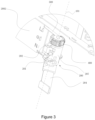
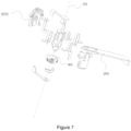
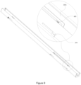
- the track adapter 1000 may stand alone, and the track adapter 1000 of this embodiment comprises a base 100, a pick-up post 200, an adjusting conductive part 300 and an adjusting knob 400.
- the base 100 is used for fixed connection to the lamp 2000, and is provided with a first central axis 101; the base 100 is used for carrying other components, the structure and shape of which may vary, and may also be a structure of a housing to accommodate other components to be mounted therein.
- All positive contacts 2021 are arranged at intervals around said first central axis 101, said negative conductive sheets 201 include negative pick-up segments 2011; the pick-up post 200 is inserted into the track and rotated to achieve electrical connection with the power supply track, the pick-up post 200 of this embodiment has a negative conductive sheet 201 and at least two positive conductive sheets 202.
- the negative and positive poles are defined as follows: For alternating current, the symbols L, N are used wherein L is the phase line that is positive, and N is the neutral line that is negative. For direct current, + indicates the positive pole and - indicates the negative pole.
- the structure is generally a U-shaped profile, and a plurality of slots extending in the extension direction are arranged on both sides, which are used for setting a conductive metal sheet L1, a conductive metal sheet L2, a conductive metal sheet L3 and a conductive metal sheet N.
- all conductive metal sheets can be set on a single side, with different numbers on both sides, and so on.
- the negative electrode section 2011 and the positive section 2022 of the pick-up post 200 can be set correspondingly.
- the negative electrode section 2011 and the positive section 2022 can be abutting and conducting with the corresponding conductive metal sheet, and the electrical connection can be realized.
- the track is a standard part, and the connection mode between the pick-up post 200 and the track is not described as they are prior art.
- the top of the pick-up post 200 refers to the portion that is first inserted into the track along the first central axis 101.
- All positive conductive sheets 202 comprise a positive pick-up section 2022 and positive contacts 2021 extending from said positive pickup section 2022 to the top of said pick-up post 200, all positive contacts 2021 are spaced around said first central axis 101;
- an adjustment conductive part 300 is rotatably provided about the first central axis 101 at the top of the pick-up post 200 and comprises a conductive contact 301 movably connected with the top of the pick-up post 200, and the moving path of the conductive contact 301 passes through all positive contacts 2021;
- the adjusting knob 400 is fixedly connected with the adjustment conductive part 300 and the rotating central axis coincides with the first central axis 101. When the adjusting knob 400 rotates, it drives the adjustment conductive part 300 to rotate so that the conductive contact 301 is electrically connected with a different positive contact 2021.
- the track adapter 1000 also includes a positive conductive connector 500 which is fixedly connected to the base 100 and stays normally conductive with the conductive contact 301 through the first rotational conductive structure 501.
- the positive conductive connector 500 may electrically connect the positive conductive sheet 202 selected by the adjusting knob 400.
- the top surface of the adjusting knob 400 is provided with an arcuate slot 402, and the inside of the arcuate slot 402 is provided with a notch 4021.
- the outer edge of the second annular conductive sheet 302 extends downward to form an arcuate conductive sheet 3021 stuck into the arc groove 402, and the extension section is the elastic member 304.
- a part of the arc conductive sheet 3021 protrudes inward into the notch 4021 to form the conductive contact 301. That is, the second annular conductive sheet 302, the elastic member 304 and the arc conductive sheet 3021 are integrally molded and manufactured to form the adjustment conductive part 300.
- the negative conductive connector 600 is provided with a first conductive surface 602 perpendicular to and intersecting with the first central axis 101.
- the second rotating conductive structure 601 includes a second conductive surface 6011 and a conductive connector 6012, and the second conductive surface 6011 is arranged against the first conductive surface 602.
- the conductive connector 6012 is electrically connected to the second conductive surface 6011 and the negative conductive sheet 201.
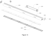
- the drive power supply 2000 of the present embodiment includes a power supply housing 2001, a circuit board 2002 and a track adapter 1000 arranged in the power supply housing, and the base 100 is fixedly connected to the power supply housing 2001.
- the power supply housing 2001 is divided into two parts, making it easier to install.
- the pick-up post 200 and the adjustment conductive part 300 are arranged in the power supply housing 2001; the top of the power supply housing 2001 is provided with a mounting hole 2003 for exposing the adjusting knob 400. At least one side is provided with a pick-up hole 2004 for the negative conductive sheet 201 and the positive conductive sheet 202 to protrude.
- the negative pick-up section 2011 and all positive pick-up sections 2022 are divided into two groups and are respectively arranged on both sides of the pick-up post 200. Both sides of the power supply housing 2001 are provided with a pick-up hole 2004.
- the circuit board 2002 is arranged on one side of the pick-up post 200, and the plane of the board body of the circuit board 2002 is arranged parallel to the first central axis 101.
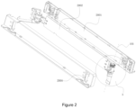
- the lamp of the present embodiment includes a lamp holder 3000, which is provided with a light source assembly 4000 and a drive power supply 2000.
- the light source assembly 4000 includes a lamp plate 4001 and an optical element 4002.
Landscapes
- Engineering & Computer Science (AREA)
- General Engineering & Computer Science (AREA)
- Arrangement Of Elements, Cooling, Sealing, Or The Like Of Lighting Devices (AREA)
Claims (20)
- Stromschienenadapter (1000), umfassend:einen Sockel (100), der fest mit einer Lampe (2000) verbunden werden kann und mit einer ersten Mittelachse (101) versehen ist;einen Aufnahmestift (200), der drehbar über der Basis (100) um die erste Mittelachse (101) vorgesehen ist, wobei der Stiftkörper mit einer negativen leitenden Schicht (201) und mindestens zwei positiven leitenden Schichten (202) versehen ist, wobei alle positiven leitenden Schichten (202) einen positiven Aufnahmeabschnitt (2022) und einen positiven Kontakt (2021) umfassen, der sich von dem positiven Aufnahmeabschnitt (2022) zum oberen Ende des Aufnahmestifts (200) erstreckt, wobei sich die Oberseite der Aufnahmesäule (200) auf den Abschnitt bezieht, der zuerst in die Spur entlang der ersten Mittelachse (101) eingeführt wird, wobei alle positiven Kontakte (2021) um die erste Mittelachse (101) herum beabstandet sind, wobei die negative leitende Folie (201) einen negativen Aufnahmeabschnitt (2011) umfasst;ein leitendes Einstellteil (300), das drehbar um die erste Mittelachse (101) der Aufnahmesäule (200) vorgesehen ist und einen leitenden Kontakt (301) aufweist, der beweglich mit der Aufnahmesäule (200) verbunden ist, wobei der leitende Kontakt (301) einen Bewegungspfad aufweist, der durch alle positiven Kontakte (2021) verläuft; undeinen Einstellknopf (400), der fest mit dem leitenden Einstellteil (300) verbunden ist und dessen zentrale Drehachse mit der ersten zentralen Achse (101) zusammenfällt;dadurch gekennzeichnet, dass das leitende Einstellteil (300) an der Oberseite der Aufnahmesäule (200) vorgesehen ist und der leitende Kontakt (301) beweglich mit der Oberseite der Aufnahmesäule (200) verbunden ist, wobei der Stromschienenadapter (1000) ferner eine positive leitende Verbindung (500) umfasst, die fest mit der Basis (100) verbunden ist und mittels einer ersten rotierenden leitenden Struktur (501) in konstanter Verbindung mit dem leitenden Kontakt (301) gehalten wird;und dass die erste rotierende leitende Struktur (501) umfasst:eine erste ringförmige leitende Platte (5011), die mit dem positiven leitenden Verbinder (500) verbunden ist;wobei das leitende Einstellteil (300) weiterhin umfasst:ein zweites ringförmiges leitfähiges Blatt (302), das fest mit dem Einstellknopf (400) verbunden ist und mittels eines elastischen Elements (304) an das erste ringförmige leitfähige Blatt (5011) gepresst und koaxial damit versehen ist, wobei der leitfähige Kontakt (301) mit dem zweiten ringförmigen leitfähigen Blatt (302) verbunden ist;einen ersten Drehzapfen (303), der in der Mitte der oberen Fläche der Aufnahmesäule (200) angeordnet ist und in die erste ringförmige leitende Platte (5011) und die zweite ringförmige leitende Platte (302) eingesetzt ist.
- Stromschienenadapter (1000) nach Anspruch 1, dadurch gekennzeichnet, dass der obere Umfang der Aufnahmesäule (200) mit Schlitzen (203) versehen ist, die in Abständen um die erste Mittelachse (101) herum angeordnet sind, wobei die positiven Kontakte (2021) in die entsprechenden Schlitze (203) eingesetzt sind.
- Stromschienenadapter (1000) nach Anspruch 2, dadurch gekennzeichnet, dass der Einstellknopf (400) mit einem Langloch (401) am Boden des Einstellknopfes (400) versehen ist, dass sich die Oberseite des Aufnahmestiftes (200) in das Langloch (401) erstreckt und dass der leitende Kontakt (301) zwischen die Außenwand des Aufnahmestiftes (200) und die Innenwand des Langloches (401) gepresst ist.
- Stromschienenadapter (1000) nach Anspruch 2, dadurch gekennzeichnet, dass der positive Aufnahmeabschnitt (2022) und der positive Kontakt (2021) mittels eines positiven U-Verbinders (2023) verbunden sind, wobei der positive U-Verbinder (2023) eine Öffnung in Richtung der Oberseite der Aufnahmesäule (200) aufweist, wobei die Aufnahmesäule (200) mit einem vorderen Stopper (204) und einem hinteren Stopper (205) versehen ist, die beide Seiten des positiven U-Verbinders (2023) einklemmen.
- Stromschienenadapter (1000) nach Anspruch 1, dadurch gekennzeichnet, dass das elastische Element (304) zwischen der zweiten ringförmigen leitenden Platte (302) und dem leitenden Kontakt (301) vorgesehen ist.
- Stromschienenadapter (1000) nach Anspruch 1, dadurch gekennzeichnet, dass der Einstellknopf (400) an der Oberseite mit einem bogenförmigen Schlitz (402) versehen ist, wobei der bogenförmige Schlitz (402) an der Innenseite mit einer Kerbe (4021) versehen ist, die Außenkante der zweiten ringförmigen leitenden Platte (302) sich nach unten erstreckt, um eine gebogene leitende Platte (3021) zu bilden, die in den gebogenen Schlitz (402) einschnappt, wobei der verlängerte Abschnitt das elastische Element (304) ist, wobei ein Teil der gebogenen leitenden Platte (3021) nach innen vorsteht, um in die Kerbe (4021) einzurasten, die den leitenden Kontakt (301) bildet.
- Stromschienenadapter (1000) nach einem der Ansprüche 1 bis 6, dadurch gekennzeichnet, dass der negative Aufnahmeabschnitt (2011) und alle positiven Aufnahmeabschnitte (2022) in zwei Gruppen unterteilt sind, die auf jeder Seite der Aufnahmesäule (200) angeordnet sind.
- Stromschienenadapter (1000) nach einem der Ansprüche 1 bis 6, dadurch gekennzeichnet, dass der Stromschienenadapter (1000) außerdem eine negative leitende Verbindung (600) umfasst, die fest mit der Basis (100) verbunden ist und mittels einer zweiten rotierenden leitenden Struktur (601) in ständiger Verbindung mit der negativen leitenden Platte (201) gehalten wird.
- Stromschienenadapter (1000) nach Anspruch 8, dadurch gekennzeichnet, dass das negative leitende Blatt (201) ferner ein negatives U-Verbindungsblatt (2012) umfasst, das mit dem negativen Aufnahmeabschnitt (2011) verbunden ist, wobei das negative U-Verbindungsblatt (2012) an der Aufnahmesäule (200) befestigt ist und in ständigem Kontakt mit der zweiten rotierenden leitenden Struktur (601) steht.
- Stromschienenadapter (1000) nach Anspruch 8, dadurch gekennzeichnet, dass der negativ leitende Verbinder (600) an einem Ende in der Nähe der negativ leitenden Platte (201) mit einer ersten leitenden Oberfläche (602) versehen ist, die senkrecht zu der ersten Mittelachse (101) steht und diese schneidet; wobei die zweite rotierende leitende Struktur (601) Folgendes umfasst:eine zweite leitende Fläche (6011), die gegen die erste leitende Fläche (602) vorgesehen ist;einen leitenden Verbinder (6012), der die zweite leitende Oberfläche (6011) und die negative leitende Schicht (201) elektrisch verbindet.
- Stromschienenadapter (1000) nach einem der Ansprüche 1 bis 6, dadurch gekennzeichnet, dass die Aufnahmesäule (200) einen Körper (206), der mit einzelnen Teilen versehen ist, und ein Gehäuse (207) umfasst, das außerhalb des Körpers (206) vorgesehen ist, wobei das Gehäuse (207) mit Ausweichlöchern (2071) versehen ist, die aus dem positiven Aufnahmeabschnitt (2022) und dem negativen Aufnahmeabschnitt (2011) herausragen.
- Antriebsstromversorgung (2000) mit einem Stromversorgungsgehäuse (2001) und einer in dem Stromversorgungsgehäuse vorgesehenen Leiterplatte (2002), dadurch gekennzeichnet, dass sie ferner einen Stromschienenadapter (1000) nach einem der Ansprüche 1 bis 11 umfasst, wobei die Basis (100) fest mit dem Stromversorgungsgehäuse (2001) verbunden ist.
- Antriebsstromversorgung (2000) nach Anspruch 12, dadurch gekennzeichnet, dass der Aufnahmestift (200) und das leitende Einstellteil (300) in dem Stromversorgungsgehäuse (2001) vorgesehen sind; das Stromversorgungsgehäuse (2001) mit einem Montageloch (2003) an der Oberseite versehen ist, damit der Einstellknopf (400) freiliegt, und mindestens eine Seite mit einem Aufnahmeloch (2004) versehen ist, damit die negative leitende Schicht (201) und/oder die positive leitende Schicht (202) herausragen.
- Antriebsstromversorgung (2000) nach Anspruch 12, dadurch gekennzeichnet, dass der negative Abnehmerabschnitt (2011) und alle positiven Abnehmerabschnitte (2022) in zwei Gruppen zu beiden Seiten des Abnehmerpfostens (200) angeordnet sind, und dass beide Seiten des Stromversorgungsgehäuses (2001) mit Abnehmerlöchern (2004) versehen sind.
- Antriebsstromversorgung (2000) nach einem der Ansprüche 12 bis 14, dadurch gekennzeichnet, dass die Leiterplatte (2002) auf einer Seite der Aufnahmesäule (200) vorgesehen ist, wobei die Ebene, in der sich der Plattenkörper der Leiterplatte (2002) befindet, parallel zur ersten Mittelachse (101) angeordnet ist.
- Antriebsstromversorgung (2000) nach einem der Ansprüche 12 bis 14, dadurch gekennzeichnet, dass die Aufnahmesäule (200) einen Drehgriff (208) aufweist, der sich von dem Stromversorgungsgehäuse (2001) aus erstreckt.
- Lampe mit einer Lampenfassung (3000), wobei die Lampenfassung (3000) mit einer Lichtquellenanordnung (4000), einer Antriebsstromversorgung (2000) und einem Stromschienenadapter (1000) nach einem der Ansprüche 1 bis 11 versehen ist und der Sockel (100) an der Lampenfassung (3000) befestigt ist.
- Lampe mit einer Lampenfassung (3000), dadurch gekennzeichnet, dass die Lampenfassung (3000) mit einer Lichtquellenanordnung (4000) und einer Antriebsstromversorgung (2000) nach einem der Ansprüche 12 bis 16 versehen ist.
- Lampe nach Anspruch 18, dadurch gekennzeichnet, dass die Lampenfassung (3000) ein U-förmiges Profil (3001) mit einer nach oben gerichteten Öffnung und Endkappen (3002) umfasst, die an beiden Enden des U-förmigen Profils (3001) vorgesehen sind, wobei die Lichtquellenbaugruppe (4000) an der Außenseite des U-förmigen Profils (3001) vorgesehen ist und der Sockel (100) am Boden der Innenseite des U-förmigen Profils (3001) vorgesehen ist; wobei die Endkappen (3002) mit einer Kerbe (3003) versehen sind, um die Schiene zu vermeiden.
- Lampe nach Anspruch 18, dadurch gekennzeichnet, dass die Aufnahmesäule (200) einen Drehgriff (208) aufweist, der sich aus dem Stromversorgungsgehäuse (2001) heraus erstreckt, und dass eine Seitenwand des U-förmigen Profils (3001) mit einem Streifenloch (3006) durch den Drehgriff (204) versehen ist.
Applications Claiming Priority (1)
| Application Number | Priority Date | Filing Date | Title |
|---|---|---|---|
| CN202110033780.XA CN112856355B (zh) | 2021-01-11 | 2021-01-11 | 一种轨道适配器、带有该适配器的驱动电源和灯具 |
Publications (2)
| Publication Number | Publication Date |
|---|---|
| EP4027467A1 EP4027467A1 (de) | 2022-07-13 |
| EP4027467B1 true EP4027467B1 (de) | 2024-07-03 |
Family
ID=76002630
Family Applications (1)
| Application Number | Title | Priority Date | Filing Date |
|---|---|---|---|
| EP21218325.5A Active EP4027467B1 (de) | 2021-01-11 | 2021-12-30 | Einen stromschienenadapter sowie dessen antriebsstromversorgung und stromschienenlicht |
Country Status (2)
| Country | Link |
|---|---|
| EP (1) | EP4027467B1 (de) |
| CN (1) | CN112856355B (de) |
Families Citing this family (8)
| Publication number | Priority date | Publication date | Assignee | Title |
|---|---|---|---|---|
| CN113405054B (zh) * | 2021-07-22 | 2025-01-28 | 广东康彩照明科技有限公司 | 具有导电控制结构的轨道灯具 |
| CN114361834A (zh) * | 2021-12-14 | 2022-04-15 | 东莞天盛电子制品有限公司 | 接电切换组件、接电盒、轨道灯输电装置和切换方法 |
| CN114263867B (zh) * | 2021-12-24 | 2025-03-11 | 东莞天盛电子制品有限公司 | 绝缘隔件、推式换接组件、轨道接电器及换接方法 |
| CN114552142B (zh) * | 2022-02-25 | 2023-09-12 | 徐州徐工汽车制造有限公司 | 电源总开关以及新能源车辆 |
| CN116711937A (zh) * | 2023-05-22 | 2023-09-08 | 博洛尼家居用品湖北有限公司 | 一种柜体板件的过线槽封边件及过线槽处理工艺 |
| CN221349050U (zh) * | 2023-11-09 | 2024-07-16 | 晨辉光宝科技股份有限公司 | 可调节的轨道灯 |
| CN118423655B (zh) * | 2024-07-02 | 2024-11-05 | 佛山汉盾光电科技有限公司 | 一种嵌入式灯具电源轨道头 |
| CN119890856B (zh) * | 2025-03-27 | 2025-06-13 | 宁波市凯迪森照明科技有限公司 | 一种轨道灯的连接模组及具有其的轨道灯 |
Family Cites Families (14)
| Publication number | Priority date | Publication date | Assignee | Title |
|---|---|---|---|---|
| FI101756B (fi) * | 1996-03-13 | 1998-08-14 | Nordic Aluminium Oyj | Virranottolaite kosketinkiskoa varten |
| CN2522733Y (zh) * | 2001-11-16 | 2002-11-27 | 林国铨 | 单轨三相多回路供电选择电气连结启控的轨道灯 |
| DE20304393U1 (de) * | 2003-03-18 | 2004-07-22 | Erco Leuchten Gmbh | Stromschienen-Adapter |
| CN101825265B (zh) * | 2010-02-07 | 2012-12-26 | 鹤山丽得电子实业有限公司 | 一种led轨道灯 |
| CN102192439B (zh) * | 2010-03-19 | 2012-12-19 | 林万炯 | Led射灯 |
| DE102012007084B4 (de) * | 2012-04-11 | 2014-04-24 | Hoffmeister Leuchten Gmbh | Adapter |
| CN204665197U (zh) * | 2015-05-06 | 2015-09-23 | 厦门上特展示系统工程有限公司 | 一种导电连接扣头及导电连接装置和应用该扣头的灯具 |
| CA2991991A1 (en) * | 2016-01-07 | 2017-03-14 | Robert A. Sonneman | Modular lighting system using hangers and power bars |
| CN207831110U (zh) * | 2017-12-29 | 2018-09-07 | 曹醒强 | 一种新型一体式导轨灯电器箱 |
| CN207835987U (zh) * | 2017-12-29 | 2018-09-07 | 曹醒强 | 一种分体式导轨灯电器箱 |
| CN111742453B (zh) * | 2018-02-28 | 2021-10-08 | 株式会社莫多勒克斯 | 配线导管用插头 |
| DE102019000410B4 (de) * | 2019-01-22 | 2022-12-08 | Paulmann Licht Gmbh | Leuchte und Adapter für Leuchte |
| CN211146219U (zh) * | 2019-12-09 | 2020-07-31 | 中山市智观照明科技有限公司 | 一种轨道驱动连接器及应用其的轨道灯 |
| CN211551536U (zh) * | 2020-03-24 | 2020-09-22 | 深圳添锦辉光电科技有限公司 | 一种取电轨道条 |
-
2021
- 2021-01-11 CN CN202110033780.XA patent/CN112856355B/zh active Active
- 2021-12-30 EP EP21218325.5A patent/EP4027467B1/de active Active
Also Published As
| Publication number | Publication date |
|---|---|
| EP4027467A1 (de) | 2022-07-13 |
| CN112856355A (zh) | 2021-05-28 |
| CN112856355B (zh) | 2023-03-28 |
Similar Documents
| Publication | Publication Date | Title |
|---|---|---|
| EP4027467B1 (de) | Einen stromschienenadapter sowie dessen antriebsstromversorgung und stromschienenlicht | |
| EP4016758A1 (de) | Spuradapter und antriebsstromversorgung und spurlicht davon | |
| US4617613A (en) | Illuminated electrical outlet cover plate | |
| US4776809A (en) | Low voltage distribution system with two-conductor track | |
| WO2017211163A1 (zh) | 转接头、照明装置 | |
| CN201368365Y (zh) | 可变脚式led日光灯 | |
| CN112815242B (zh) | 灯带端盖组件及led灯带结构 | |
| CN215061917U (zh) | 一种轨道适配器、带有该适配器的驱动电源和轨道灯 | |
| CN212298686U (zh) | 轨道头及轨道灯 | |
| CN205678464U (zh) | 转接头、照明装置 | |
| KR930000643B1 (ko) | 램프부착 배니티 미러 | |
| CN109546375B (zh) | 联动开启式带灯电瓶夹 | |
| CN221447010U (zh) | 一种开关及其指示灯组件结构 | |
| CA1304120C (en) | Low voltage electrical distribution system | |
| CN218119488U (zh) | 灯具的接线端子安装结构及灯具 | |
| CN109194012B (zh) | 吊扇快装接线盒 | |
| CN222352274U (zh) | 一种具有便捷式安装取电结构的照明灯具 | |
| CN1030479C (zh) | 插座式袖珍显微镜 | |
| CN217503487U (zh) | 吸顶灯具及吸顶灯组 | |
| CN222011825U (zh) | 电源分体式照明装置 | |
| CN113405054A (zh) | 具有导电控制结构的轨道灯具 | |
| CN221237809U (zh) | 一种极简导电轨道及配件 | |
| CN218216034U (zh) | 连接结构及感应灯具 | |
| CN222616759U (zh) | 一种安装稳定的磁吸灯轨道转角连接模块 | |
| CN218032768U (zh) | 一种用于线槽灯的led灯带 |
Legal Events
| Date | Code | Title | Description |
|---|---|---|---|
| PUAI | Public reference made under article 153(3) epc to a published international application that has entered the european phase |
Free format text: ORIGINAL CODE: 0009012 |
|
| STAA | Information on the status of an ep patent application or granted ep patent |
Free format text: STATUS: THE APPLICATION HAS BEEN PUBLISHED |
|
| AK | Designated contracting states |
Kind code of ref document: A1 Designated state(s): AL AT BE BG CH CY CZ DE DK EE ES FI FR GB GR HR HU IE IS IT LI LT LU LV MC MK MT NL NO PL PT RO RS SE SI SK SM TR |
|
| STAA | Information on the status of an ep patent application or granted ep patent |
Free format text: STATUS: REQUEST FOR EXAMINATION WAS MADE |
|
| 17P | Request for examination filed |
Effective date: 20230111 |
|
| RBV | Designated contracting states (corrected) |
Designated state(s): AL AT BE BG CH CY CZ DE DK EE ES FI FR GB GR HR HU IE IS IT LI LT LU LV MC MK MT NL NO PL PT RO RS SE SI SK SM TR |
|
| GRAP | Despatch of communication of intention to grant a patent |
Free format text: ORIGINAL CODE: EPIDOSNIGR1 |
|
| STAA | Information on the status of an ep patent application or granted ep patent |
Free format text: STATUS: GRANT OF PATENT IS INTENDED |
|
| INTG | Intention to grant announced |
Effective date: 20240314 |
|
| GRAS | Grant fee paid |
Free format text: ORIGINAL CODE: EPIDOSNIGR3 |
|
| GRAA | (expected) grant |
Free format text: ORIGINAL CODE: 0009210 |
|
| STAA | Information on the status of an ep patent application or granted ep patent |
Free format text: STATUS: THE PATENT HAS BEEN GRANTED |
|
| AK | Designated contracting states |
Kind code of ref document: B1 Designated state(s): AL AT BE BG CH CY CZ DE DK EE ES FI FR GB GR HR HU IE IS IT LI LT LU LV MC MK MT NL NO PL PT RO RS SE SI SK SM TR |
|
| REG | Reference to a national code |
Ref country code: CH Ref legal event code: EP |
|
| REG | Reference to a national code |
Ref country code: DE Ref legal event code: R096 Ref document number: 602021015122 Country of ref document: DE |
|
| REG | Reference to a national code |
Ref country code: LT Ref legal event code: MG9D |
|
| REG | Reference to a national code |
Ref country code: NL Ref legal event code: MP Effective date: 20240703 |
|
| PG25 | Lapsed in a contracting state [announced via postgrant information from national office to epo] |
Ref country code: PT Free format text: LAPSE BECAUSE OF FAILURE TO SUBMIT A TRANSLATION OF THE DESCRIPTION OR TO PAY THE FEE WITHIN THE PRESCRIBED TIME-LIMIT Effective date: 20241104 |
|
| REG | Reference to a national code |
Ref country code: AT Ref legal event code: MK05 Ref document number: 1700822 Country of ref document: AT Kind code of ref document: T Effective date: 20240703 |
|
| PG25 | Lapsed in a contracting state [announced via postgrant information from national office to epo] |
Ref country code: NL Free format text: LAPSE BECAUSE OF FAILURE TO SUBMIT A TRANSLATION OF THE DESCRIPTION OR TO PAY THE FEE WITHIN THE PRESCRIBED TIME-LIMIT Effective date: 20240703 |
|
| PG25 | Lapsed in a contracting state [announced via postgrant information from national office to epo] |
Ref country code: PT Free format text: LAPSE BECAUSE OF FAILURE TO SUBMIT A TRANSLATION OF THE DESCRIPTION OR TO PAY THE FEE WITHIN THE PRESCRIBED TIME-LIMIT Effective date: 20241104 Ref country code: NL Free format text: LAPSE BECAUSE OF FAILURE TO SUBMIT A TRANSLATION OF THE DESCRIPTION OR TO PAY THE FEE WITHIN THE PRESCRIBED TIME-LIMIT Effective date: 20240703 |
|
| PG25 | Lapsed in a contracting state [announced via postgrant information from national office to epo] |
Ref country code: NO Free format text: LAPSE BECAUSE OF FAILURE TO SUBMIT A TRANSLATION OF THE DESCRIPTION OR TO PAY THE FEE WITHIN THE PRESCRIBED TIME-LIMIT Effective date: 20241003 |
|
| PG25 | Lapsed in a contracting state [announced via postgrant information from national office to epo] |
Ref country code: FI Free format text: LAPSE BECAUSE OF FAILURE TO SUBMIT A TRANSLATION OF THE DESCRIPTION OR TO PAY THE FEE WITHIN THE PRESCRIBED TIME-LIMIT Effective date: 20240703 Ref country code: GR Free format text: LAPSE BECAUSE OF FAILURE TO SUBMIT A TRANSLATION OF THE DESCRIPTION OR TO PAY THE FEE WITHIN THE PRESCRIBED TIME-LIMIT Effective date: 20241004 Ref country code: PL Free format text: LAPSE BECAUSE OF FAILURE TO SUBMIT A TRANSLATION OF THE DESCRIPTION OR TO PAY THE FEE WITHIN THE PRESCRIBED TIME-LIMIT Effective date: 20240703 |
|
| PG25 | Lapsed in a contracting state [announced via postgrant information from national office to epo] |
Ref country code: BG Free format text: LAPSE BECAUSE OF FAILURE TO SUBMIT A TRANSLATION OF THE DESCRIPTION OR TO PAY THE FEE WITHIN THE PRESCRIBED TIME-LIMIT Effective date: 20240703 |
|
| PG25 | Lapsed in a contracting state [announced via postgrant information from national office to epo] |
Ref country code: LV Free format text: LAPSE BECAUSE OF FAILURE TO SUBMIT A TRANSLATION OF THE DESCRIPTION OR TO PAY THE FEE WITHIN THE PRESCRIBED TIME-LIMIT Effective date: 20240703 |
|
| PG25 | Lapsed in a contracting state [announced via postgrant information from national office to epo] |
Ref country code: IS Free format text: LAPSE BECAUSE OF FAILURE TO SUBMIT A TRANSLATION OF THE DESCRIPTION OR TO PAY THE FEE WITHIN THE PRESCRIBED TIME-LIMIT Effective date: 20241103 Ref country code: AT Free format text: LAPSE BECAUSE OF FAILURE TO SUBMIT A TRANSLATION OF THE DESCRIPTION OR TO PAY THE FEE WITHIN THE PRESCRIBED TIME-LIMIT Effective date: 20240703 |
|
| PG25 | Lapsed in a contracting state [announced via postgrant information from national office to epo] |
Ref country code: HR Free format text: LAPSE BECAUSE OF FAILURE TO SUBMIT A TRANSLATION OF THE DESCRIPTION OR TO PAY THE FEE WITHIN THE PRESCRIBED TIME-LIMIT Effective date: 20240703 Ref country code: CZ Free format text: LAPSE BECAUSE OF FAILURE TO SUBMIT A TRANSLATION OF THE DESCRIPTION OR TO PAY THE FEE WITHIN THE PRESCRIBED TIME-LIMIT Effective date: 20240703 |
|
| PG25 | Lapsed in a contracting state [announced via postgrant information from national office to epo] |
Ref country code: RS Free format text: LAPSE BECAUSE OF FAILURE TO SUBMIT A TRANSLATION OF THE DESCRIPTION OR TO PAY THE FEE WITHIN THE PRESCRIBED TIME-LIMIT Effective date: 20241003 Ref country code: ES Free format text: LAPSE BECAUSE OF FAILURE TO SUBMIT A TRANSLATION OF THE DESCRIPTION OR TO PAY THE FEE WITHIN THE PRESCRIBED TIME-LIMIT Effective date: 20240703 |
|
| PG25 | Lapsed in a contracting state [announced via postgrant information from national office to epo] |
Ref country code: RS Free format text: LAPSE BECAUSE OF FAILURE TO SUBMIT A TRANSLATION OF THE DESCRIPTION OR TO PAY THE FEE WITHIN THE PRESCRIBED TIME-LIMIT Effective date: 20241003 Ref country code: PL Free format text: LAPSE BECAUSE OF FAILURE TO SUBMIT A TRANSLATION OF THE DESCRIPTION OR TO PAY THE FEE WITHIN THE PRESCRIBED TIME-LIMIT Effective date: 20240703 Ref country code: NO Free format text: LAPSE BECAUSE OF FAILURE TO SUBMIT A TRANSLATION OF THE DESCRIPTION OR TO PAY THE FEE WITHIN THE PRESCRIBED TIME-LIMIT Effective date: 20241003 Ref country code: LV Free format text: LAPSE BECAUSE OF FAILURE TO SUBMIT A TRANSLATION OF THE DESCRIPTION OR TO PAY THE FEE WITHIN THE PRESCRIBED TIME-LIMIT Effective date: 20240703 Ref country code: IS Free format text: LAPSE BECAUSE OF FAILURE TO SUBMIT A TRANSLATION OF THE DESCRIPTION OR TO PAY THE FEE WITHIN THE PRESCRIBED TIME-LIMIT Effective date: 20241103 Ref country code: HR Free format text: LAPSE BECAUSE OF FAILURE TO SUBMIT A TRANSLATION OF THE DESCRIPTION OR TO PAY THE FEE WITHIN THE PRESCRIBED TIME-LIMIT Effective date: 20240703 Ref country code: GR Free format text: LAPSE BECAUSE OF FAILURE TO SUBMIT A TRANSLATION OF THE DESCRIPTION OR TO PAY THE FEE WITHIN THE PRESCRIBED TIME-LIMIT Effective date: 20241004 Ref country code: FI Free format text: LAPSE BECAUSE OF FAILURE TO SUBMIT A TRANSLATION OF THE DESCRIPTION OR TO PAY THE FEE WITHIN THE PRESCRIBED TIME-LIMIT Effective date: 20240703 Ref country code: ES Free format text: LAPSE BECAUSE OF FAILURE TO SUBMIT A TRANSLATION OF THE DESCRIPTION OR TO PAY THE FEE WITHIN THE PRESCRIBED TIME-LIMIT Effective date: 20240703 Ref country code: CZ Free format text: LAPSE BECAUSE OF FAILURE TO SUBMIT A TRANSLATION OF THE DESCRIPTION OR TO PAY THE FEE WITHIN THE PRESCRIBED TIME-LIMIT Effective date: 20240703 Ref country code: BG Free format text: LAPSE BECAUSE OF FAILURE TO SUBMIT A TRANSLATION OF THE DESCRIPTION OR TO PAY THE FEE WITHIN THE PRESCRIBED TIME-LIMIT Effective date: 20240703 Ref country code: AT Free format text: LAPSE BECAUSE OF FAILURE TO SUBMIT A TRANSLATION OF THE DESCRIPTION OR TO PAY THE FEE WITHIN THE PRESCRIBED TIME-LIMIT Effective date: 20240703 |
|
| REG | Reference to a national code |
Ref country code: DE Ref legal event code: R097 Ref document number: 602021015122 Country of ref document: DE |
|
| PGFP | Annual fee paid to national office [announced via postgrant information from national office to epo] |
Ref country code: DE Payment date: 20241220 Year of fee payment: 4 |
|
| PG25 | Lapsed in a contracting state [announced via postgrant information from national office to epo] |
Ref country code: SM Free format text: LAPSE BECAUSE OF FAILURE TO SUBMIT A TRANSLATION OF THE DESCRIPTION OR TO PAY THE FEE WITHIN THE PRESCRIBED TIME-LIMIT Effective date: 20240703 Ref country code: DK Free format text: LAPSE BECAUSE OF FAILURE TO SUBMIT A TRANSLATION OF THE DESCRIPTION OR TO PAY THE FEE WITHIN THE PRESCRIBED TIME-LIMIT Effective date: 20240703 Ref country code: RO Free format text: LAPSE BECAUSE OF FAILURE TO SUBMIT A TRANSLATION OF THE DESCRIPTION OR TO PAY THE FEE WITHIN THE PRESCRIBED TIME-LIMIT Effective date: 20240703 |
|
| PG25 | Lapsed in a contracting state [announced via postgrant information from national office to epo] |
Ref country code: EE Free format text: LAPSE BECAUSE OF FAILURE TO SUBMIT A TRANSLATION OF THE DESCRIPTION OR TO PAY THE FEE WITHIN THE PRESCRIBED TIME-LIMIT Effective date: 20240703 |
|
| PG25 | Lapsed in a contracting state [announced via postgrant information from national office to epo] |
Ref country code: SK Free format text: LAPSE BECAUSE OF FAILURE TO SUBMIT A TRANSLATION OF THE DESCRIPTION OR TO PAY THE FEE WITHIN THE PRESCRIBED TIME-LIMIT Effective date: 20240703 Ref country code: IT Free format text: LAPSE BECAUSE OF FAILURE TO SUBMIT A TRANSLATION OF THE DESCRIPTION OR TO PAY THE FEE WITHIN THE PRESCRIBED TIME-LIMIT Effective date: 20240703 |
|
| PLBE | No opposition filed within time limit |
Free format text: ORIGINAL CODE: 0009261 |
|
| STAA | Information on the status of an ep patent application or granted ep patent |
Free format text: STATUS: NO OPPOSITION FILED WITHIN TIME LIMIT |
|
| 26N | No opposition filed |
Effective date: 20250404 |
|
| PG25 | Lapsed in a contracting state [announced via postgrant information from national office to epo] |
Ref country code: MC Free format text: LAPSE BECAUSE OF FAILURE TO SUBMIT A TRANSLATION OF THE DESCRIPTION OR TO PAY THE FEE WITHIN THE PRESCRIBED TIME-LIMIT Effective date: 20240703 |
|
| REG | Reference to a national code |
Ref country code: CH Ref legal event code: PL |
|
| PG25 | Lapsed in a contracting state [announced via postgrant information from national office to epo] |
Ref country code: LU Free format text: LAPSE BECAUSE OF NON-PAYMENT OF DUE FEES Effective date: 20241230 |
|
| PG25 | Lapsed in a contracting state [announced via postgrant information from national office to epo] |
Ref country code: SE Free format text: LAPSE BECAUSE OF FAILURE TO SUBMIT A TRANSLATION OF THE DESCRIPTION OR TO PAY THE FEE WITHIN THE PRESCRIBED TIME-LIMIT Effective date: 20240703 |
|
| REG | Reference to a national code |
Ref country code: BE Ref legal event code: MM Effective date: 20241231 |
|
| PG25 | Lapsed in a contracting state [announced via postgrant information from national office to epo] |
Ref country code: BE Free format text: LAPSE BECAUSE OF NON-PAYMENT OF DUE FEES Effective date: 20241231 |
|
| PG25 | Lapsed in a contracting state [announced via postgrant information from national office to epo] |
Ref country code: FR Free format text: LAPSE BECAUSE OF NON-PAYMENT OF DUE FEES Effective date: 20241231 |
|
| PG25 | Lapsed in a contracting state [announced via postgrant information from national office to epo] |
Ref country code: CH Free format text: LAPSE BECAUSE OF NON-PAYMENT OF DUE FEES Effective date: 20241231 |
|
| PG25 | Lapsed in a contracting state [announced via postgrant information from national office to epo] |
Ref country code: IE Free format text: LAPSE BECAUSE OF NON-PAYMENT OF DUE FEES Effective date: 20241230 |