EP4016553B1 - Ladekabel, vorrichtung sowie verfahren zur herstellung des ladekabels - Google Patents
Ladekabel, vorrichtung sowie verfahren zur herstellung des ladekabels Download PDFInfo
- Publication number
- EP4016553B1 EP4016553B1 EP21216684.7A EP21216684A EP4016553B1 EP 4016553 B1 EP4016553 B1 EP 4016553B1 EP 21216684 A EP21216684 A EP 21216684A EP 4016553 B1 EP4016553 B1 EP 4016553B1
- Authority
- EP
- European Patent Office
- Prior art keywords
- cable
- diameter
- charging
- cylinder
- sub
- Prior art date
- Legal status (The legal status is an assumption and is not a legal conclusion. Google has not performed a legal analysis and makes no representation as to the accuracy of the status listed.)
- Active
Links
Images




Classifications
-
- H—ELECTRICITY
- H01—ELECTRIC ELEMENTS
- H01B—CABLES; CONDUCTORS; INSULATORS; SELECTION OF MATERIALS FOR THEIR CONDUCTIVE, INSULATING OR DIELECTRIC PROPERTIES
- H01B13/00—Apparatus or processes specially adapted for manufacturing conductors or cables
- H01B13/008—Apparatus or processes specially adapted for manufacturing conductors or cables for manufacturing extensible conductors or cables
-
- B—PERFORMING OPERATIONS; TRANSPORTING
- B60—VEHICLES IN GENERAL
- B60L—PROPULSION OF ELECTRICALLY-PROPELLED VEHICLES; SUPPLYING ELECTRIC POWER FOR AUXILIARY EQUIPMENT OF ELECTRICALLY-PROPELLED VEHICLES; ELECTRODYNAMIC BRAKE SYSTEMS FOR VEHICLES IN GENERAL; MAGNETIC SUSPENSION OR LEVITATION FOR VEHICLES; MONITORING OPERATING VARIABLES OF ELECTRICALLY-PROPELLED VEHICLES; ELECTRIC SAFETY DEVICES FOR ELECTRICALLY-PROPELLED VEHICLES
- B60L53/00—Methods of charging batteries, specially adapted for electric vehicles; Charging stations or on-board charging equipment therefor; Exchange of energy storage elements in electric vehicles
- B60L53/10—Methods of charging batteries, specially adapted for electric vehicles; Charging stations or on-board charging equipment therefor; Exchange of energy storage elements in electric vehicles characterised by the energy transfer between the charging station and the vehicle
- B60L53/14—Conductive energy transfer
- B60L53/18—Cables specially adapted for charging electric vehicles
-
- B—PERFORMING OPERATIONS; TRANSPORTING
- B65—CONVEYING; PACKING; STORING; HANDLING THIN OR FILAMENTARY MATERIAL
- B65H—HANDLING THIN OR FILAMENTARY MATERIAL, e.g. SHEETS, WEBS, CABLES
- B65H75/00—Storing webs, tapes, or filamentary material, e.g. on reels
- B65H75/02—Cores, formers, supports, or holders for coiled, wound, or folded material, e.g. reels, spindles, bobbins, cop tubes, cans, mandrels or chucks
- B65H75/34—Cores, formers, supports, or holders for coiled, wound, or folded material, e.g. reels, spindles, bobbins, cop tubes, cans, mandrels or chucks specially adapted or mounted for storing and repeatedly paying-out and re-storing lengths of material provided for particular purposes, e.g. anchored hoses, power cables
- B65H75/36—Cores, formers, supports, or holders for coiled, wound, or folded material, e.g. reels, spindles, bobbins, cop tubes, cans, mandrels or chucks specially adapted or mounted for storing and repeatedly paying-out and re-storing lengths of material provided for particular purposes, e.g. anchored hoses, power cables without essentially involving the use of a core or former internal to a stored package of material, e.g. with stored material housed within casing or container, or intermittently engaging a plurality of supports as in sinuous or serpentine fashion
-
- B—PERFORMING OPERATIONS; TRANSPORTING
- B65—CONVEYING; PACKING; STORING; HANDLING THIN OR FILAMENTARY MATERIAL
- B65H—HANDLING THIN OR FILAMENTARY MATERIAL, e.g. SHEETS, WEBS, CABLES
- B65H2701/00—Handled material; Storage means
- B65H2701/30—Handled filamentary material
- B65H2701/34—Handled filamentary material electric cords or electric power cables
-
- Y—GENERAL TAGGING OF NEW TECHNOLOGICAL DEVELOPMENTS; GENERAL TAGGING OF CROSS-SECTIONAL TECHNOLOGIES SPANNING OVER SEVERAL SECTIONS OF THE IPC; TECHNICAL SUBJECTS COVERED BY FORMER USPC CROSS-REFERENCE ART COLLECTIONS [XRACs] AND DIGESTS
- Y02—TECHNOLOGIES OR APPLICATIONS FOR MITIGATION OR ADAPTATION AGAINST CLIMATE CHANGE
- Y02T—CLIMATE CHANGE MITIGATION TECHNOLOGIES RELATED TO TRANSPORTATION
- Y02T10/00—Road transport of goods or passengers
- Y02T10/60—Other road transportation technologies with climate change mitigation effect
- Y02T10/70—Energy storage systems for electromobility, e.g. batteries
-
- Y—GENERAL TAGGING OF NEW TECHNOLOGICAL DEVELOPMENTS; GENERAL TAGGING OF CROSS-SECTIONAL TECHNOLOGIES SPANNING OVER SEVERAL SECTIONS OF THE IPC; TECHNICAL SUBJECTS COVERED BY FORMER USPC CROSS-REFERENCE ART COLLECTIONS [XRACs] AND DIGESTS
- Y02—TECHNOLOGIES OR APPLICATIONS FOR MITIGATION OR ADAPTATION AGAINST CLIMATE CHANGE
- Y02T—CLIMATE CHANGE MITIGATION TECHNOLOGIES RELATED TO TRANSPORTATION
- Y02T10/00—Road transport of goods or passengers
- Y02T10/60—Other road transportation technologies with climate change mitigation effect
- Y02T10/7072—Electromobility specific charging systems or methods for batteries, ultracapacitors, supercapacitors or double-layer capacitors
-
- Y—GENERAL TAGGING OF NEW TECHNOLOGICAL DEVELOPMENTS; GENERAL TAGGING OF CROSS-SECTIONAL TECHNOLOGIES SPANNING OVER SEVERAL SECTIONS OF THE IPC; TECHNICAL SUBJECTS COVERED BY FORMER USPC CROSS-REFERENCE ART COLLECTIONS [XRACs] AND DIGESTS
- Y02—TECHNOLOGIES OR APPLICATIONS FOR MITIGATION OR ADAPTATION AGAINST CLIMATE CHANGE
- Y02T—CLIMATE CHANGE MITIGATION TECHNOLOGIES RELATED TO TRANSPORTATION
- Y02T90/00—Enabling technologies or technologies with a potential or indirect contribution to GHG emissions mitigation
- Y02T90/10—Technologies relating to charging of electric vehicles
- Y02T90/14—Plug-in electric vehicles
Definitions
- the invention relates to a charging cable for charging an electric vehicle, a method and a corresponding device for producing a charging cable.
- Electric vehicles are usually charged via the general power grid. To do this, an electric vehicle must drive to a charging station (charging station, wallbox, etc.) and an energy storage device in the electric vehicle must be electrically connected to the charging station. The electrical connection is typically made using a charging cable.
- a charging station charging station, wallbox, etc.
- the charging cable provided must not only have the necessary electrical properties to complete the charging process of a high-voltage battery, but it must also overcome the distance between the battery and the charging station, which can extend over several meters.
- the invention is therefore based on the object of shaping a charging cable in such a way that the cable can be stowed away again easily and in a space-saving manner after use.
- the charging cable should be wound in the rest position in such a way that the bending radii recommended by the cable manufacturer are adhered to.
- the winding of the charging cable should be compact in order to take up as little space as possible, e.g. B. in the trunk of the electric vehicle.
- a charging cable with the features of claim 1, which can be easily stored in a conical coil.
- the charging cable of the present invention includes a cable section and at least one connection element at one end of the cable section.
- the connection element is used for electrical connection to a charging socket of an electric vehicle or an energy source external to the vehicle.
- the other end of the cable section can be equipped with a second connection element.
- the charging cable can be integrated into an electric vehicle or a charging station. In this case, one end of the cable section is firmly connected to the electric vehicle or the charging station.
- the cable section is shaped in such a way that the cable section is held in a rest position with a restoring force, in which the cable section has several turns.
- the cable section has at least three subsections, each with at least one turn, wherein a first diameter of a first subsection is larger than a second diameter of a second subsection and the second diameter is larger than a third diameter of a third subsection. At least one subsection has two or more turns of the same diameter.
- the first subsection has at least two turns with the first diameter
- the second subsection has at least two turns with the second diameter
- the third subsection has at least two turns with the third diameter
- the cable section is shaped in such a way that it falls back into its rest position after use.
- the difference between the first and second diameters and between the second and third diameters is greater than twice the diameter of the cable section; In a preferred embodiment of the invention, the difference is in the range of 2 times to 4 times, more preferably in the range of 2.5 times to 3.5 times, the diameter of the cable section.
- a difference that is at least three times as large as the diameter of the cable section is even more preferred.
- the diameter of the turns is in a range between 8 and 15 times the diameter of the cable section.
- the bending radius must be at least 10 times the cable diameter.
- the number of turns in each subsection should preferably be between 2 and 5. In a preferred embodiment of the invention, the number of turns with the same diameter is between 2 and 4. In a further preferred embodiment of the invention, the Cable section two turns in the first subsection and three turns each in the second and third subsections.
- the turns have a substantially round shape.
- the number of subsections is not limited to 3 and the cable section may also have 4 or more subsections depending on the length of the charging cable.
- the length of the charging cable can be between 4m and 7m. In a preferred embodiment of the invention, the length of the charging cable is less than 6m. In a further preferred embodiment of the invention, the length of the charging cable is less than 5.5m. The number of turns depends on the length of the cable section.
- the charging cable comprises a connection element at a first end of a cable section of the charging cable and a second end which forms a fixed electrical connection to the energy source of the charging station.
- the connection element is suitable for electrically connecting the energy source of the charging station to a battery of an electric vehicle.
- the charging station can include a charging station, a wallbox, or similar.
- the charging cable is then stored in the charging station so that the charging cable is not visible from the outside. In this way, the charging cable is not only neatly stowed away, but it is also protected from the weather.
- the charging cable is integrated into an electric vehicle.
- the charging cable is then stowed in the vehicle, for example behind the license plate.
- a further aspect of the invention relates to a device for producing a charging cable with a conical winding according to claim 9.
- the cylinders each have a first base area as a base area and a second base area opposite the first base area.
- At least one base area of the cylinders is closed in order to enable stacking.
- At least one base area of the cylinders is designed to be open in order to enable them to be placed one inside the other.
- the cylinders are firmly connected to one another.
- first height between the first base area and the second base area of the first cylinder
- second height between the second base area of the first cylinder and the second base area of the second cylinder
- second height between the second base area of the second cylinder and the second base area of the third cylinder given a third height
- the first, second and third heights in the first and second embodiments may differ, since in the first embodiment the respective height determines how many turns of the cable section can be wound on the corresponding cylinder, while in the second embodiment the turns are also in the gap can be arranged between the first and second cylinders and the space between the second and third cylinders.
- the first height preferably determines the maximum number of turns, while the second and third heights preferably correspond to at least one thickness of the cable section.
- the device is arranged on a base plate which is preferably circular or teardrop-shaped.
- the device preferably has means in the area of the edges of the lateral surface to the second base area for fixing the cable sections wound on the device.
- through holes can also be provided instead, through which cable ties or the like can be passed to fix the cable section.
- the base plate preferably also has corresponding means for fixing or through holes. These are placed in such a way that the free ends of the cable section wound on the device can preferably be fixed.
- the cable section is teardrop-shaped, so that one end of the cable section can be arranged in the pointed region of the teardrop-shaped baseplate.
- the user has more space available in this area, so that the end can be fixed without bending.
- the other end, which is fixed to the lateral surface of the third cylinder, is in the air anyway, so that it can also be fixed without bending.
- the second embodiment of the device in order to improve the transfer of the cable section from the lateral surface of the first cylinder with the largest diameter to the lateral surface of the middle second cylinder and from there in turn to the lateral surface of the third cylinder, it is preferably provided that along the edge of the second base surface in the A rectangular section is recessed on the lateral surface of the first cylinder and the second cylinder.
- the height of the section preferably corresponds approximately to the thickness of the cable section.
- the rectangular, recessed section preferably has a length that corresponds to half to a quarter of the circumference of the respective lateral surface.
- a tab is provided on a vertical edge (parallel to the central axis of the respective cylinder) of the lateral surface, preferably on the side opposite to the winding direction, which is connected to the lateral surface at right angles to the base surface and which extends in the direction of the lateral surface of the second or the third cylinder is guided without touching it.
- the distance between the tab and the respective cylinder corresponds at least to the thickness of the cable section, preferably 1.5 times, more preferably 2 times the thickness of the cable section.
- the difference between the first and second diameters and between the second and third diameters is in the range of 2 times to 4 times, more preferably in the range of 2.5 times to 3.5 times, the diameter of the cable section.
- the difference is at least three times as large as the diameter of the cable section.
- the diameter of the first cylinder is between 250mm and 280mm
- the diameter of the second cylinder is between 190mm and 220mm
- the diameter of the third cylinder is between 130mm and 160mm.
- the first, the second, the third cylinder and optionally the base plate preferably consist of wood, aluminum sheet or stainless steel sheet, preferably aluminum sheet or stainless steel sheet.
- a further aspect of the invention relates to a method according to claim 12.
- the wound cable section is heated according to a temperature profile between 25°C and 130°C.
- the temperature profile consists of a warm-up time, a holding time and a cooling time.
- the warm-up time can be approx. 25 minutes, with the temperature rising from 25°C to 130°C.
- the warm-up time allows the plastic of the cable jacket to slowly soften.
- the holding time begins. This is approx. 25 minutes at 130°C.
- the cable is then cooled to room temperature for approx. 1 hour.
- These parameters may vary depending on the volume of the annealing oven and the material of the cable jacket.
- the cable After annealing and the cooling phase, the cable is counter-wound, which increases the restoring force. Counter-winding automatically increases the diameter by 25 to 35 mm. This affects all three subsections.
- the charging cable of the present invention has a very compact and space-saving coiled shape. By tempering the cable section, a stable deformation of the cable section occurs, which independently forms back into the conical winding (rest position) due to the associated restoring force.
- the user only needs to pull the charging cable axially during use, ie in a direction parallel to the axis of the windings, and connect the connection element to the car or to the charging station.
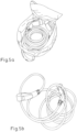
- the cable section of the charging cable automatically returns to its conical rest position, as in Fig. 5a shown. This ensures easy handling and easy storage of the charging cable.
- the selected winding radii are particularly advantageous, as they ensure dimensional stability and compliance with the recommended bending radii, so that damage to the charging cable is avoided.
- the cable section can be pulled apart almost completely, which ensures optimal use of the length and a reduced overall length of the charging cable compared to other winding methods.
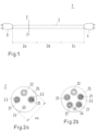
- FIG. 1 A schematic representation of a charging cable is shown.
- the charging cable 1 comprises a cable section 2 and connection elements 3, 4 at both ends of the cable section 2.
- the charging cable 1 can have a single connection element 3, 4, for example if the charging cable 1 is in an electric vehicle or in a charging station (charging station, Wallbox, etc.) is integrated.
- the cable section may comprise a commercially available cable that meets the requirements for charging an electric vehicle. Typically a 1-phase or 3-phase cable with a rating between 16A and 32A is used.
- Figs. 2a and 2b show a cross-sectional view of a cable section 2 along II 'in Fig. 1 , where Fig. 2a a 1-phase cable and Fig. 2b shows a 3-phase cable.
- the cable section 2 comprises at least two inner conductors 21, a ground wire 22 and a control wire 24.
- the inner conductors 21, control wire and ground wire 22 are covered by an insulating material 23 and the insulated inner conductors, ground wire and control wire are embedded in a jacket 25 made of plastic.
- an inner conductor 21 consists of several copper strands, but other materials and embodiments can also be used.
- the jacket 25 preferably consists of shape memory polymers that have a shape memory effect.
- the jacket 25 may contain an elastic polymer.
- Non-limiting examples are TPE or TPU.
- the typical diameter Dk of the cable section 2 can be between 12mm and 32mm.
- the diameter Dk of the cable section 2 is preferably between 12mm and 20mm.
- a straight charging cable 1 is shown.
- the cable section 2 is no longer straight in the rest position, but is arranged in a stable conical coil.
- Fig. 3 shows a schematic side view
- Fig. 4 shows a schematic top view of the winding of a charging cable according to the invention, in which the cable section 2 is arranged in several turns with different radii.
- the first subsection 2a of the cable section 2 forms two turns with a first diameter D1
- the second subsection 2d forms three turns with a second diameter D2
- the third subsection 2c forms three turns with a third diameter D3.
- the turns of the first subsection 2a lie one above the other.
- the first diameter D1 is larger than the second diameter D2, so that the turns of the second subsection 2b are arranged completely within the turns of the first subsection 2a, see Fig. 4 .
- the turns of the second subsection 2b which have the same diameter D2 also lie one above the other and the second diameter D2 is larger than the third diameter D3, so that the turns of the third subsection 2c - which also lie one above the other - are completely within the Windings of the second subsection 2b are arranged.
- the difference between the first and second diameters D1-D2, as well as between the second and third diameters D2-D3, must be greater than 2.5 times the diameter Dk of the cable section 2. Furthermore, the difference should not be greater than 3.5 times the cable diameter: 2.5 ⁇ Dk ⁇ D 1 ⁇ D 2 ⁇ 3.5 ⁇ Dk , 2.5 ⁇ Dk ⁇ D 2 ⁇ D 3 ⁇ 3.5 ⁇ Dk be.
- the difference between the first and second diameters D1-D2 and between the second and third diameters D2-D3 is at least three times as large as the diameter Dk of the cable section 2.
- Fig. 3 It is further shown how the cable section 2 of the charging cable 1 can be easily pulled out of the wound rest position by pulling one end of the third subsection 2c along the vertical direction Z.
- the Z direction runs parallel to the axis of rotation of the turns.
- a connection element 4 is plugged into the charging station, while the other connection element is coupled to an electric vehicle. This creates an electrical connection between the vehicle and the charging station and the charging cycle can be completed.
- the cable section contracts due to the restoring force and springs back to its rest position.
- Fig. 5a shows an illustration of a charging cable according to the invention in the rest position.
- the conical winding has a diameter that essentially corresponds to the first diameter D1 and a height that corresponds to the product of the diameter Dk of the cable section 2 and the number of turns.
- the conical winding of the charging cable is particularly compact and stable compared to conventional charging cables. Because at least two turns with the same diameter are provided, the first diameter is relatively small in comparison, e.g. B., to a snail-shaped winding. Furthermore, because the number of turns with the same diameter is relatively small, the overall height of the winding is significantly reduced, e.g. B. in comparison with a helical winding.
- the charging cable 1 according to the present invention has a compact winding and can be easily and neatly stored as shown in Figure 5a you can see.
- Fig. 5b a conventional charging cable, ie a charging cable that has not been subjected to a thermal shaping process.
- a conventional charging cable is either lying unorganized, for example in the trunk of an electric vehicle, or it has to be laboriously folded. In both cases, bends occur that are improper and can lead to damage to the charging cable.
- the diameter of the turns is between 5 and 20 times, preferably between 8 and 15 times, the cable diameter Dk: 8th ⁇ D / Dk ⁇ 15 , in which D represents each of the first, second and third diameters D1, D2, D3, and Dk represents the diameter of the cable section.
- the compact conical winding of the charging cable according to the invention has a relatively small diameter, for example approximately 30 cm or smaller, and can easily be stored in a correspondingly round storage bag, as in Fig. 5a shown.
- the storage bag can also be equipped with a Velcro fastener to attach to the floor of the trunk.
- the cable In order to obtain such a conical winding from the cable, the cable must be subjected to a thermal forming process, which is described in detail below.
- Fig. 6 shows a device according to the invention, which is used for producing a conically wound charging cable.
- the device 50 includes a first cylinder 51 with a first diameter d1, a second cylinder 52 with a second diameter d2 smaller than the first diameter d1, and a third cylinder 53 with a third diameter d3 smaller than the second diameter d2.
- the three cylinders are stacked along the vertical direction Z.
- the number of cylinders is not limited to 3 and the device 50 may also have 4 or more cylinders depending on the length of the charging cable.
- the device can also have a base plate (substrate) on which the cylinders are arranged.
- the base plate (substrate) and the cylinders can be made, for example, from wood or other suitable materials such as aluminum sheet and stainless steel sheet.
- the first, second and third diameters d1, d2, d3 of the cylinders 51, 52, 53 essentially correspond to the first, second and third diameters D1, D2, D3 of the turns of the cable section 2, each of the first, second and third diameters d1 , d2, d3 of the cylinders 51, 52, 53 is slightly smaller than the corresponding first, second and third diameters D1, D2, D3 of the turns of the cable section 2. Accordingly, the difference (D1-d1) is usually (1-2) Dk. In the same way, the difference (D2-d2) and the difference (D3-d3) are between Dk and 2 Dk.
- Fig. 7 shows a schematic cross-sectional representation of the device 50 from Fig. 6 .
- a cable section of the desired length is wound and fastened around the cylinders, with a first subsection 2a of the cable section 2 being wound around the first cylinder 51, a second subsection 2b around the second cylinder 52 and a third subsection 2c being wound around the third cylinder 53 .
- the height H1, H2, H3 of the cylinders 51, 52, 53 corresponds approximately to the product of the cable diameter Dk and the number of turns in the corresponding subsection 2a, 2b, 2c.
- the device 50 including the cable section 2 is heated in a tempering oven.
- the cable section is heated according to a temperature profile between 25°C and 130°C for approx. 50 minutes, with the warm-up time and the holding time each being approx. 25 minutes.
- the temperature is increased from 25°C to 130°C and then held at 130°C for approx. 25 minutes (holding time).
- the warm-up time is used to slowly soften the plastic of the cable jacket.
- the cable section 2 wound on the device 50 is then cooled down to room temperature.
- connection elements 3, 4 are then attached to one end or both ends of the cable section 2.
- the first cylinder 51 has a first diameter d1 of 250mm
- the second cylinder 52 has a second diameter d2 of 190mm
- the third cylinder 53 has a third diameter of 130mm.
- Such a device 50 is suitable for cable sections 2 with a diameter between 12mm and 17mm.
- the number of subsections 2a, 2b, 2c can also be greater than 3, depending on the total length of the charging cable 1.
- the cable section can have 4 or more subsections.
- the three cylinders 51, 52, 53 are arranged one inside the other.
- a base surface 54 of the cylinders 51, 52, 53 is provided as a base surface 54 and the base side 55 opposite the base surface 54 is designed to be open in order to enable the cylinders 51, 52, 53 to be placed one inside the other.
- the turns of the cable section 2 can also be arranged in a gap 56 between the first and second cylinders 51, 52 and the gap 57 between the second and third cylinders 53, 53.
- the device 50 is arranged on a drop-shaped base plate 58. Furthermore, the device 50 has in the area of the free edge to the lateral surface 59 of the third cylinder 53 through holes 60 for fixing the cable section 2 wound on the device 50 ( Fig. 9 ) using a cable tie 61.
- the Base plate 58 has two adjacent through holes 62 in the pointed region, through which a cable tie 63 is guided, by means of which one end of the cable section 2 is fixed ( Fig. 9 ).
- a rectangular section 66 is recessed along the edge of the base surface 55 opposite the base surface 54 in the lateral surface 64, 65 of the first cylinder 51 and the second cylinder 52.
- the height of the section 66 preferably corresponds approximately to the thickness of the cable section 2.
- the rectangular, recessed section 66 preferably has a length which corresponds to half to a quarter of the circumference of the respective lateral surface 64, 65.
- a tab 68 is provided, which is connected to the lateral surface 64, 65 at a right angle to the standing surface 54 and in the direction of the lateral surface 65, 59 of the second or third cylinder 52, 53 is guided without touching it.
Landscapes
- Engineering & Computer Science (AREA)
- Manufacturing & Machinery (AREA)
- Power Engineering (AREA)
- Transportation (AREA)
- Mechanical Engineering (AREA)
- Electric Propulsion And Braking For Vehicles (AREA)
- Charge And Discharge Circuits For Batteries Or The Like (AREA)
Description
- Die Erfindung betrifft ein Ladekabel zum Aufladen eines elektrischen Fahrzeuges, ein Verfahren sowie eine entsprechende Vorrichtung zur Herstellung eines Ladekabels.
- Elektrofahrzeuge werden in der Regel über das allgemeine Stromnetz geladen. Dazu muss ein Elektrofahrzeug zu einer Ladestation (Ladesäule, Wallbox, usw.) fahren und ein Energiespeicher des Elektrofahrzeuges muss mit der Ladestation elektrisch verbunden werden. Die elektrische Verbindung erfolgt typischerweise mittels eines Ladekabels.
- Das dazu vorgesehene Ladekabel muss nicht nur die notwendigen elektrischen Eigenschaften aufweisen, um den Ladeprozess einer Hochspannung-Batterie zu erfüllen, sondern es muss auch die Distanz zwischen Batterie und Ladestation überwinden, welche sich über mehrere Meter erstrecken kann.
- Dies führt zu einem ziemlich sperrigen und voluminösen Ladekabel, welches nach dem Ladeprozess - meistens im Auto - wieder verstaut werden muss. Das Kabel wird dann mühsam vom Benutzer aufgerollt und verstaut oder einfach in den Kofferraum hineingeworfen. In beiden Fällen verursacht das Aufrollen/Ausrollen des Kabels eine Torsion im Kabelinneren, welche zu Beschädigungen bis zu Brüchen von Einzeladern führen kann. Je länger das Ladekabel ist, umso umständlicher wird das Verstauen des Ladekabels. Darüber hinaus bilden die Anschlussstellen zwischen Kabel und den schweren Ladestecker besonders anfällige Stellen, die zu Schaden kommen können, wenn das Ladekabel nicht ordnungsgemäß verstaut wird.
- Es ist wünschenswert, ein Verstausystem für ein Ladekabel zu entwickeln, das das Verstauen des Ladekabels erleichtert und Schäden an dem Ladekabel selbst vorbeugen kann.
- Der Erfindung liegt daher die Aufgabe zugrunde, ein Ladekabel derart zu formen, dass das Kabel nach dem Gebrauch einfach und platzsparend wieder verstaut werden kann. Insbesondere sollte das Ladekabel in der Ruhestellung so aufgewickelt sein, dass die vom Kabelhersteller empfohlenen Biegeradien eingehalten werden. Gleichzeitig sollte die Aufwicklung des Ladekabels kompakt sein, um möglichst wenig Platz, z. B. im Kofferraum des Elektrofahrzeuges, einzunehmen.
- Die Aufgabe wird erfindungsgemäß durch ein Ladekabel mit den Merkmalen des Anspruchs 1, das sich einfach in einer konischen Aufwicklung verstauen lässt, gelöst.
- Das Ladekabel der vorliegenden Erfindung umfasst einen Kabelabschnitt und mindestens ein Anschlusselement an einem Ende des Kabelabschnittes. Das Anschlusselement dient zur elektrischen Verbindung mit einer Ladebuchse eines elektrischen Fahrzeuges oder einer fahrzeugexternen Energiequelle. Das andere Ende des Kabelabschnittes kann mit einem zweiten Anschlusselement ausgestattet sein. Alternativ kann das Ladekabel in ein elektrisches Fahrzeug oder eine Ladestation integriert sein. In diesem Fall ist ein Ende des Kabelabschnittes fest mit dem elektrischen Fahrzeug oder der Ladestation verbunden. Der Kabelabschnitt ist derart geformt, dass der Kabelabschnitt mit einer Rückstellkraft in einer Ruhestellung gehalten wird, in der der Kabelabschnitt mehrere Windungen aufweist. Der Kabelabschnitt weist mindestens drei Unterabschnitte mit jeweils mindestens eine Windung auf, wobei ein erster Durchmesser eines ersten Unterabschnitts größer als ein zweiter Durchmesser eines zweiten Unterabschnitts und der zweite Durchmesser größer als ein dritter Durchmesser eines dritten Unterabschnitts ist. Mindestens ein Unterabschnitt weist zwei oder mehr Windungen mit dem gleichen Durchmesser auf.
- Erfindungsgemäß weist der erste Unterabschnitt mindestens zwei Windungen mit dem ersten Durchmesser auf, der zweite Unterabschnitt mindestens zwei Windungen mit dem zweiten Durchmesser auf, und der dritte Unterabschnitt mindestens zwei Windungen mit dem dritten Durchmesser auf.
- Der Kabelabschnitt ist derart geformt, dass er nach dem Gebrauch in seine Ruhestellung zurückfällt.
- Erfindungsgemäß ist die Differenz zwischen dem ersten und zweiten Durchmesser und zwischen dem zweiten und dritten Durchmesser größer als das Doppelte des Durchmessers des Kabelabschnittes; in einer bevorzugten Ausgestaltung der Erfindung liegt die Differenz im Bereich des 2-faches bis 4-faches, noch bevorzugter im Bereich des 2,5-fachen bis 3,5-fachen, des Durchmessers des Kabelabschnittes.
- Noch bevorzugter wird eine Differenz, die mindestens dreimal so groß wie der Durchmesser des Kabelabschnittes ist.
- Um die Struktur des Kabelabschnittes nicht zu beschädigen, ist es vorteilhaft, wenn der Durchmesser der Windungen in einem Bereich zwischen dem 8- und 15-fachen des Durchmessers des Kabelabschnittes liegt. Bei Gleichstrom muss der Biegeradius mindestens das 10-faches des Kabeldurchmessers betragen.
- Die Anzahl der Windungen in jedem Unterabschnitt, d.h. der Windungen mit dem gleichen Durchmesser, sollte vorzugsweise zwischen 2 und 5 liegen. In einer bevorzugten Ausgestaltung der Erfindung liegt die Anzahl der Windungen mit gleichem Durchmesser zwischen 2 und 4. In einer weiteren bevorzugten Ausgestaltung der Erfindung umfasst der Kabelabschnitt zwei Windungen im ersten Unterabschnitt und jeweils drei Windungen im zweiten und dritten Unterabschnitt.
- Die Windungen weisen eine im Wesentlichen runde Form auf.
- Die Anzahl der Unterabschnitte ist nicht auf 3 begrenzt und der Kabelabschnitt kann auch 4 oder mehr Unterabschnitte aufweisen, je nach Länge des Ladekabels.
- Die Länge des Ladekabels kann zwischen 4m und 7m betragen. In einer bevorzugten Ausgestaltung der Erfindung beträgt die Länge des Ladekabels weniger als 6m. In einer weiteren bevorzugten Ausgestaltung der Erfindung beträgt die Länge des Ladekabels weniger als 5,5m. Die Anzahl der Windungen hängt von der Länge des Kabelabschnittes ab.
- Ein weiterer Aspekt der Erfindung betrifft eine Ladestation mit integriertem Ladekabel. Das Ladekabel umfasst ein Anschlusselement an einem ersten Ende eines Kabelabschnittes des Ladekabels und ein zweites Ende, das einen festen elektrischen Anschluss zur Energiequelle der Ladestation bildet. Das Anschlusselement ist dazu geeignet, die Energiequelle der Ladestation mit einer Batterie eines Elektrofahrzeuges elektrisch zu verbinden. Die Ladestation kann eine Ladesäule, eine Wallbox, o.ä. umfassen. Das Ladekabel wird dann in der Ladestation verstaut, so dass das Ladekabel von außen nicht sichtbar ist. Auf dieser Weise wird das Ladekabel nicht nur ordentlich verstaut, sondern es wird auch vor Witterung geschützt.
- In einer weiteren Ausgestaltung der Erfindung ist das Ladekabel in ein elektrisches Fahrzeug integriert. Das Ladekabel wird dann im Fahrzeug verstaut, beispielweise hinter dem Kennzeichen.
- Ein weiterer Aspekt der Erfindung betrifft eine Vorrichtung zur Herstellung eines Ladekabels mit konischer Aufwicklung gemäß Anspruch 9.
- Die Zylinder weisen jeweils eine erste Grundfläche als Standfläche und eine der ersten Grundfläche gegenüberliegende zweite Grundfläche auf.
- Bei der gestapelten ersten Ausführungsform der Vorrichtung ist jeweils zumindest eine Grundfläche der Zylinder geschlossen, um das Stapeln zu ermöglichen.
- Bei der zweiten Ausführungsform der Vorrichtung ist zumindest eine Grundfläche der Zylinder offen ausgebildet ist, um das ineinander Stellen zu ermöglichen.
- Bei beiden Ausführungsformen sind die Zylinder fest miteinander verbunden.
- Zwischen der ersten Grundfläche und der zweiten Grundfläche des ersten Zylinders ist eine erste Höhe, zwischen der zweiten Grundfläche des ersten Zylinders und der zweiten Grundfläche des zweiten Zylinders ist eine zweite Höhe und zwischen der zweiten Grundfläche des zweiten Zylinders und der zweiten Grundfläche des dritten Zylinders ist eine dritte Höhe gegeben.
- Die erste, zweite und dritte Höhe bei der ersten und zweiten Ausführungsform können sich unterscheiden, da bei der ersten Ausführungsform die jeweilige Höhe bestimmt, wieviel Windungen des Kabelabschnitts auf den entsprechenden Zylinder gewickelt werden können, während bei der zweiten Ausführungsform die Windungen auch in dem Zwischenraum zwischen dem ersten und dem zweiten Zylinder und dem Zwischenraum zwischen dem zweiten und dem dritten Zylinder angeordnet werden können. Die erste Höhe bestimmt vorzugsweise wiederum die maximale Anzahl der Windungen, während die zweite und dritte Höhe vorzugsweise zumindest einer Stärke des Kabelabschnitts entspricht.
- Nach einer besonders bevorzugten Ausführungsform ist die Vorrichtung auf einer Grundplatte angeordnet, die vorzugsweise kreisförmig oder tropfenförmig ausgebildet ist.
- Bevorzugt weist die Vorrichtung im Bereich der Kanten der Mantelfläche zur zweiten Grundfläche Mittel zur Festlegung der auf die Vorrichtung gewickelten Kabelabschnitte auf. Alternativ können stattdessen auch Durchgangsbohrungen vorgesehen sein, durch die Kabelbinder oder dergleichen zur Festlegung des Kabelabschnitts geführt werden können. Bevorzugt weist auch die Grundplatte entsprechende Mittel zur Festlegung oder Durchgangsbohrungen auf. Dabei werden diese derart platziert, dass bevorzugt die freien Enden des auf der Vorrichtung aufgewickelten Kabelabschnitts fixiert werden können.
- Zur Fixierung des einen Endes des Kabelabschnitts auf der Grundplatte ist es vorteilhaft, wenn diese tropfenförmig ist, so dass das eine Ende des Kabelabschnitts im spitz ausgeformten Bereich der tropfenförmigen Grundplatte angeordnet werden kann. Vorteilhafterweise steht dem Nutzer in diesem Bereich mehr Platz zur Verfügung, so dass das Ende ohne Biegung fixiert werden kann. Bei dem anderen Ende, welches an der Mantelfläche des dritten Zylinders fixiert wird, befindet sich das Ende ohnehin in der Luft, so dass auch dieses ohne Biegung fixiert werden kann.
- Bei der zweiten Ausführungsform der Vorrichtung ist vorzugsweise zur Verbesserung der Überleitung des Kabelabschnitts von der Mantelfläche des ersten Zylinders mit dem größten Durchmesser zur Mantelfläche des mittleren zweiten Zylinders und von dort wiederum zur Mantelfläche des dritteln Zylinders vorgesehen, dass entlang der Kante der zweiten Grundfläche in der Mantelfläche des ersten Zylinders und des zweiten Zylinders ein rechteckiger Abschnitt ausgespart ist. Die Höhe des Abschnitts entspricht bevorzugt in etwa der Stärke des Kabelabschnitts. Der rechteckige, ausgesparte Abschnitt weist vorzugsweise eine Länge auf, die der Hälfte bis ein Viertel des Umfangs der jeweiligen Mantelfläche entspricht.
- Vorzugsweise ist an einer vertikalen Kante (parallel zur Mittelachse des jeweiligen Zylinders) der Mantelfläche, vorzugsweise an der Seite entgegen der Wickelrichtung eine Lasche vorgesehen, die mit der Mantelfläche im rechten Winkel zur Grundfläche verbunden ist und die in Richtung zur Mantelfläche des zweiten bzw. des dritten Zylinders geführt ist, ohne diesen zu berühren.
- Der Abstand der Lasche zum jeweiligen Zylinder entspricht zumindest der Stärke des Kabelabschnitts, vorzugsweise des 1,5- fachen, mehr bevorzugt des 2-fachen der Stärke des Kabelabschnitts.
- Es ist vorteilhaft, wenn die Differenz zwischen dem ersten und zweiten Durchmesser und zwischen dem zweiten und dritten Durchmesser im Bereich des 2-faches bis 4-faches, noch bevorzugter im Bereich des 2,5-fachen bis 3,5-fachen, des Durchmessers des Kabelabschnittes liegt. Vorzugsweise ist die Differenz mindestens dreimal so groß wie der Durchmesser des Kabelabschnittes.
- In einer bevorzugten Ausgestaltung der Erfindung liegt der Durchmesser des ersten Zylinders zwischen 250mm und 280mm, der Durchmesser des zweiten Zylinders zwischen 190mm und 220mm und der Durchmesser des dritten Zylinders zwischen 130mm und 160mm. Vorzugsweise bestehen der erste, der zweite, der dritte Zylinder und gegebenenfalls die Grundplatte aus Holz, Aluminium-Blech oder Edelstahl-Blech, vorzugsweise aus Aluminium-Blech oder Edelstahl-Blech.
- Ein weiterer Aspekt der Erfindung betrifft ein Verfahren gemäß Anspruch 12.
- Vorzugsweise wird der aufgewickelte Kabelabschnitt entsprechend eines Temperaturprofils zwischen 25°C und 130°C erhitzt. Das Temperaturprofil setzt sich aus einer Aufwärmzeit, einer Haltezeit und einer Abkühlzeit zusammen. Beispielsweise kann die Aufwärmzeit ca. 25min betragen, wobei die Temperatur von 25°C bis auf 130°C ansteigt. Die Aufwärmzeit dient dazu, dass der Kunststoff des Kabelmantels langsam aufweicht. Sobald die Zieltemperatur erreicht ist, beginnt die Haltezeit. Diese beträgt ca. 25min bei 130°C. Anschließend wird das Kabel ca. 1 Stunde auf Zimmertemperatur abgekühlt. Diese Parameter können je nach Volumen des Temper-Ofens und Material des Kabelmantels variieren.
- Nach dem Tempern und der Abkühlphase wird das Kabel gegengewickelt, wodurch die Rückstellkraft erhöht wird. Durch das Gegenwickeln wird der Durchmesser automatisch um 25 bis 35 mm größer. Dies betrifft alle drei Unterabschnitte.
- Das Ladekabel der vorliegenden Erfindung weist eine sehr kompakte und platzsparende aufgewickelte Form auf. Durch das Temperieren des Kabelabschnittes erfolgt eine stabile Verformung des Kabelabschnittes, welcher sich durch die damit verbundene Rückstellkraft eigenständig in die konische Aufwicklung (Ruhestellung) zurückformt.
- Der Nutzer braucht lediglich das Ladekabel bei der Benutzung axial zu ziehen, d.h. in eine Richtung parallel zur Achse der Windungen, und das Anschlusselement am Auto, bzw. an der Ladestation anzuschließen. Nach dem Gebrauch, springt der Kabelabschnitt des Ladekabels eigenständig in seine konische Ruhestellung zurück, wie in
Fig. 5a gezeigt. Damit sind eine einfache Handhabung und ein leichtes Verstauen des Ladekabels gewährleistet. - Besonders vorteilhaft sind die gewählten Windungsradien, welche für Formstabilität und Einhaltung der empfohlenen Biegeradien sorgen, so dass eine Beschädigung des Ladekabels vermieden wird. Dazu lässt sich der Kabelabschnitt fast komplett auseinanderziehen, was für eine optimale Längennutzung und eine reduzierte Gesamtlänge des Ladekabels im Vergleich zu anderen Aufwicklungsmethoden sorgt.
- Nachfolgend wird die Erfindung anhand bevorzugter Ausführungsbeispiele unter Bezugnahme auf die Figuren näher erläutert. Hierbei zeigen:
- Fig. 1
- eine schematische Darstellung eines erfindungsgemäßen Ladekabels,
- Fig. 2a-2b
- Querschnittsdarstellungen eines Kabelabschnittes entlang Querschnitt I-I' in
Fig. 1 , - Fig. 3
- eine schematische Darstellung der Aufwicklung eines erfindungsgemäßen Ladekabels,
- Fig. 4
- eine schematische Aufsicht der Aufwicklung eines erfindungsgemäßen Ladekabels,
- Fig. 5a
- eine Abbildung eines erfindungsgemäßen Ladekabels in der Ruhestellung mit einer zugehörigen Aufbewahrungstasche,
- Fig. 5b
- eine Abbildung eines konventionellen Ladekabels,
- Fig. 6
- eine schematische Darstellung einer Vorrichtung zur Herstellung eines erfindungsgemäßen Ladekabels,
- Fig. 7
- eine schematische Querschnittsdarstellung der Vorrichtung von
Fig. 6 . - Fig. 8
- eine perspektivische Ansicht einer Vorrichtung zur Herstellung eines erfindungsgemäßen Ladekabels nach einer zweiten Ausführungsform, und
- Fig. 9
- eine perspektivische Ansicht der Vorrichtung nach
Fig. 8 mit einem aufgewickelten Kabelabschnitt. - In
Fig. 1 ist eine schematische Darstellung eines Ladekabels gezeigt. Das Ladekabel 1 umfasst einen Kabelabschnitt 2 und Anschlusselemente 3, 4 an beiden Enden des Kabelabschnittes 2. In weiteren Ausführungsvarianten kann das Ladekabel 1 einen einzigen Anschlusselement 3, 4 aufweisen, z.B. wenn das Ladekabel 1 in ein elektrisches Fahrzeug oder in eine Ladestation (Ladesäule, Wallbox, usw.) integriert ist. - Der Kabelabschnitt kann ein handelsübliches Kabel aufweisen, das die Anforderungen für das Aufladen eines elektrischen Fahrzeuges erfüllt. Typischerweise wird ein 1-phasiges oder 3-phasiges Kabel mit einer Belastbarkeit zwischen 16A und 32A verwendet.
-
Fig. 2a und 2b zeigen eine Querschnittsdarstellung eines Kabelabschnittes 2 entlang I-I' inFig. 1 , wobeiFig. 2a ein 1-phasiges Kabel undFig. 2b ein 3-phasiges Kabel zeigt. Der Kabelabschnitt 2 umfasst mindestens zwei Innenleiter 21, eine Erdungsader 22 und eine Steuerader 24. Die Innenleiter 21, Steuerader und Erdungsader 22 sind von einem Isolationsmaterial 23 umhüllt und die isolierten Innenleiter, Erdungsader und Steuerader sind in einen Mantel 25 aus Kunststoff eingebettet. Typischerweise besteht ein Innenleiter 21 aus mehreren Kupferlitzen, aber weitere Materialien und Ausführungsformen können auch verwendet werden. - Der Mantel 25 besteht vorzugsweise aus Formgedächtnis-Polymeren, die einen Shape-Memory-Effekt aufweisen. Beispielweise kann der Mantel 25 ein elastisches Polymer enthalten. Nicht einschränkende Beispiele sind TPE oder TPU.
- Der typische Durchmesser Dk des Kabelabschnittes 2 kann zwischen 12mm und 32mm liegen. Vorzugsweise liegt der Durchmesser Dk des Kabelabschnittes 2 zwischen 12mm und 20mm.
- In
Fig. 1 wird der Einfachheit halber ein gerades Ladekabel 1 gezeigt. Im Endprodukt der vorliegenden Erfindung, d.h. nach dem thermischen Formungsprozess, ist der Kabelabschnitt 2 in der Ruhestellung nicht mehr geradlinig, sondern es ist in einer stabilen konischen Aufwicklung angeordnet. -
Fig. 3 zeigt eine schematische seitliche Darstellung undFig. 4 zeigt eine schematische Aufsichtsdarstellung der Aufwicklung eines erfindungsgemäßen Ladekabels, in der der Kabelabschnitt 2 in mehreren Windungen mit unterschiedlichen Radien angeordnet ist. Im Ausführungsbeispiel vonFig. 3 bildet der erste Unterabschnitt 2a des Kabelabschnittes 2 zwei Windungen mit einem ersten Durchmesser D1, der zweite Unterabschnitt 2d drei Windungen mit einem zweiten Durchmesser D2 und der dritte Unterabschnitt 2c drei Windungen mit einem dritten Durchmesser D3. - Wie in
Fig. 3 dargestellt, liegen die Windungen des ersten Unterabschnittes 2a, welche den gleichen Durchmesser D1 haben, übereinander. Der erste Durchmesser D1 ist größer als der zweite Durchmesser D2, so dass die Windungen des zweiten Unterabschnittes 2b vollständig innerhalb der Windungen des ersten Unterabschnittes 2a angeordnet sind, sieheFig. 4 . Auf gleiche Weise liegen die Windungen des zweiten Unterabschnittes 2b, welche den gleichen Durchmesser D2 haben, auch übereinander und der zweite Durchmesser D2 ist größer als der dritte Durchmesser D3, so dass die Windungen des dritten Unterabschnittes 2c - die ebenso übereinander liegen - vollständig innerhalb der Windungen des zweiten Unterabschnittes 2b angeordnet sind. - Damit dies gewährleistet wird, muss die Differenz zwischen dem ersten und zweiten Durchmesser D1-D2, sowie zwischen dem zweiten und dritten Durchmesser D2-D3, größer als das 2,5-fache des Durchmessers Dk des Kabelabschnittes 2 sein. Ferner sollte die Differenz nicht größer als das 3,5-fache des Kabeldurchmessers:


- In einer bevorzugten Ausführungsform der vorliegenden Erfindung, ist die Differenz zwischen dem ersten und zweiten Durchmesser D1-D2 sowie zwischen dem zweiten und dritten Durchmesser D2-D3 mindestens dreimal so groß wie der Durchmesser Dk des Kabelabschnittes 2.
- In
Fig. 3 wird weiter gezeigt, wie der Kabelabschnitt 2 des Ladekabels 1 aus der aufgewickelten Ruhestellung einfach ausgezogen werden kann, in dem ein Ende des dritten Unterabschnittes 2c entlang der vertikalen Richtung Z gezogen wird. Die Richtung Z verläuft parallel zur Drehachse der Windungen. Dann wird ein Anschlusselement 4 an der Ladestation eingesteckt, während das andere Anschlusselement an ein elektrisches Fahrzeug gekoppelt wird. Damit wird eine elektrische Verbindung zwischen Fahrzeug und Ladestation hergestellt und der Ladezyklus kann vollzogen werden. Nach dem Gebrauch zieht sich der Kabelabschnitt durch die Rückstellkraft zusammen und springt in seine Ruhestellung zurück. -
Fig. 5a zeigt eine Abbildung eines erfindungsgemäßen Ladekabels in der Ruhestellung. Die konische Aufwicklung weist einen Durchmesser, der im Wesentlichen dem ersten Durchmesser D1 entspricht, und eine Höhe, die dem Produkt aus Durchmesser Dk des Kabelabschnittes 2 und Anzahl der Windungen entspricht, auf. Dadurch ist die konische Aufwicklung des Ladekabels besonders kompakt und stabil im Vergleich zu konventionellen Ladekabeln. Weil mindestens zwei Windungen mit dem gleichen Durchmesser vorgesehen sind, ist der erste Durchmesser relativ klein im Vergleich, z. B., zu einer schneckenförmigen Aufwicklung. Ferner, weil die Anzahl der Windungen mit dem gleichen Durchmesser relativ klein ist, ist die Gesamthöhe der Aufwicklung deutlich verringert, z. B. im Vergleich mit einer wendelförmigen Aufwicklung. - Das Ladekabel 1 gemäß der vorliegenden Erfindung weist eine kompakte Aufwicklung auf und kann einfach und ordentlich verstaut werden, wie in
Figur 5a zu sehen ist. Im Vergleich dazu zeigtFig. 5b ein konventionelles Ladekabel, d.h. ein Ladekabel, welches keinem thermischen Formgebungsverfahren ausgesetzt worden ist. Demzufolge liegt ein konventionelles Ladekabel entweder ungeordnet, z.B. im Kofferraum eines Elektrofahrzeuges, oder es muss aufwendig zusammengelegt werden. In beiden Fällen entstehen Verbiegungen, die nicht sachgemäß sind und zu einer Beschädigung des Ladekabels führen können. - Um Beschädigungen vorzubeugen, ist es vorteilhaft das Ladekabel so aufzuwickeln, dass der Durchmesser der Windungen zwischen dem 5- bis 20-fachen, bevorzugt zwischen dem 8- und 15-fachen, des Kabeldurchmessers Dk beträgt:

- Die kompakte konische Aufwicklung des erfindungsgemäßen Ladekabels hat einen relativ kleinen Durchmesser, beispielweise von ca. 30 cm oder kleiner, und kann unproblematisch in eine entsprechend runde Aufbewahrungstasche verstaut werden, wie in
Fig. 5a dargestellt. Die Aufbewahrungstasche kann zusätzlich mit einem Klettverschluss ausgestattet sein, um am Boden des Kofferraums befestigt zu werden. - Damit eine solche konische Aufwicklung vom Kabel erhalten wird, muss das Kabel einem thermischen Formgebungsprozess unterzogen werden, welcher im Folgenden im Detail beschrieben wird.
-
Fig. 6 zeigt eine erfindungsgemäße Vorrichtung, welche für die Herstellung eines konisch-aufgewickelten Ladekabels verwendet wird. - Die Vorrichtung 50 umfasst einen ersten Zylinder 51 mit einem ersten Durchmesser d1, einen zweiten Zylinder 52 mit einem zweiten Durchmesser d2 kleiner als der erste Durchmesser d1, und einen dritten Zylinder 53 mit einem dritten Durchmesser d3 kleiner als der zweite Durchmesser d2. Die drei Zylinder sind entlang der vertikalen Richtung Z aufeinandergestapelt. Die Anzahl der Zylinder ist nicht auf 3 begrenzt und die Vorrichtung 50 kann auch 4 oder mehr Zylinder aufweisen, je nach Länge des Ladekabels.
- Die Vorrichtung kann weiterhin eine Grundplatte (Substrat) aufweisen, worauf die Zylinder angeordnet sind. Die Grundplatte (Substrat) und die Zylinder können beispielweise aus Holz oder anderen geeigneten Materialien wie z.B. Aluminium-Blech und Edelstahl-Blech angefertigt werden. Der erste, zweite und dritte Durchmesser d1, d2, d3 der Zylinder 51, 52, 53 entsprechen im Wesentlichen dem ersten, zweiten und dritten Durchmesser D1, D2, D3 der Windungen des Kabelabschnittes 2, wobei jeder der ersten, zweiten und dritten Durchmesser d1, d2, d3 der Zylinder 51, 52, 53 etwas kleiner als der entsprechende erste, zweite und dritte Durchmesser D1, D2, D3 der Windungen des Kabelabschnittes 2 ist. Entsprechend beträgt die Differenz (D1-d1) in der Regel (1-2)·Dk. Auf gleiche Weise liegt auch die Differenz (D2-d2) sowie die Differenz (D3-d3) zwischen Dk und 2 Dk.
-
Fig. 7 zeigt eine schematische Querschnittsdarstellung der Vorrichtung 50 vonFig. 6 . Hier wird ein Kabelabschnitt in der gewünschten Länge um die Zylinder aufgewickelt und befestigt, wobei ein erster Unterabschnitt 2a des Kabelabschnittes 2 um den ersten Zylinder 51, ein zweiter Unterabschnitt 2b um den zweiten Zylinder 52 und ein dritter Unterabschnitt 2c um den dritten Zylinder 53 aufgewickelt wird. Die Höhe H1, H2, H3 der Zylindern 51, 52, 53 entspricht ungefähr dem Produkt aus Kabeldurchmesser Dk und Anzahl der Windungen in dem entsprechenden Unterabschnitt 2a, 2b, 2c. - Nach dem Wickelprozess wird die Vorrichtung 50 samt Kabelabschnitt 2 in einem Temper-Ofen erhitzt. Typischerweise wird der Kabelabschnitt entsprechend einem Temperaturprofil zwischen 25°C und 130°C für ca. 50min erhitzt, wobei die Aufwärmzeit und die Haltezeit jeweils ca. 25min betragen. Während der Aufwärmzeit wird die Temperatur von 25°C bis auf 130°C erhöht, und dann bei 130°C ca. 25min gehalten (Haltezeit). Die Aufwärmzeit dient dazu, den Kunststoff des Kabelmantels langsam aufzuweichen. Anschließend wird der auf der Vorrichtung 50 aufgewickelte Kabelabschnitt 2 auf Zimmertemperatur heruntergekühlt.
- Während des Temperprozesses wird der Mantel 25 des Kabelabschnittes 2 verformt, d.h. auf der Außenseite der Windungen wird der Mantel 25 gedehnt und auf der Innenseite wird er zusammengedrückt. Durch den thermischen Prozess wird sich die aufgewickelte Form im Material des Mantels 25 einprägen, so dass die Form nach dem Abkühlen stabil erhalten wird. Anschließend werden Anschlusselemente 3, 4 an ein Ende oder an beide Enden des Kabelabschnittes 2 angebracht.
- In einem bevorzugten Ausführungsbeispiel hat der erste Zylinder 51 einen ersten Durchmesser d1 von 250mm, der zweite Zylinder 52 einen zweiten Durchmesser d2 von 190mm und der dritte Zylinder 53 einen dritten Durchmesser von 130 mm. Eine solche Vorrichtung 50 ist für Kabelabschnitte 2 mit einem Durchmesser zwischen 12mm und 17mm geeignet.
- Obwohl das Ausführungsbeispiel in
Fig. 3 und4 zwei Windungen mit dem ersten Durchmesser D1, und jeweils drei Windungen mit dem zweiten und dritten Durchmesser aufweist, dient dies nur als beispielhafte Ausführungsform und eine davon abweichende Anzahl von ersten, zweiten und dritten Windungen ist weiterhin möglich, wobei die Anzahl von Windungen mit dem gleichen Durchmesser zwischen 2 und 5 liegen kann. - Ferner kann auch die Anzahl der Unterabschnitte 2a, 2b, 2c größer als 3 sein, je nach Gesamtlänge des Ladekabels 1. Beispielweise kann der Kabelabschnitt 4 oder mehr Unterabschnitte aufweisen.
- Bei der zweiten Ausführungsform der Vorrichtung 50, die in den
Fig. 8 und9 dargestellt ist, sind die drei Zylinder 51, 52, 53 ineinander stehend angeordnet. Dazu ist eine Grundfläche 54 der Zylinder 51, 52, 53 als Standfläche 54 vorgesehen und die der Standfläche 54 gegenüberliegende Grundseite 55 ist offen ausgebildet, um das ineinander Stellen der Zylinder 51, 52, 53 zu ermöglichen. - Bei der zweiten Ausführungsform der Vorrichtung 50 können die Windungen des Kabelabschnitts 2 auch in einem Zwischenraum 56 zwischen dem ersten und dem zweiten Zylinder 51, 52 und dem Zwischenraum 57 zwischen dem zweiten und dem dritten Zylinder 53, 53 angeordnet werden können. Die Vorrichtung 50 ist auf einer tropfenförmig ausgeformten Grundplatte 58 angeordnet, Weiterhin weist die Vorrichtung 50 im Bereich der freien Kante zur Mantelfläche 59 des dritten Zylinders 53 Durchgangsbohrungen 60 zur Festlegung des auf die Vorrichtung 50 gewickelten Kabelabschnitts 2 (
Fig. 9 ) mittels eines Kabelbinders 61 auf. Zur Fixierung des einen Endes des Kabelabschnitts 2 ist auf der Grundplatte 58 im spitz ausgeformten Bereich zwei benachbarte Durchgangsbohrungen 62 vorgesehen, durch die ein Kabelbinder 63 geführt ist mittels dem des eine Ende des Kabelabschnitts 2 festgelegt ist (Fig. 9 ). - Bei der zweiten Ausführungsform der Vorrichtung 50 ist zudem zur Verbesserung der Überleitung des Kabelabschnitts 2 von der Mantelfläche 64 des ersten Zylinders 51 mit dem größten Durchmesser zur Mantelfläche 65 des mittleren zweiten Zylinders 52 und von dort wiederum zur Mantelfläche 59 des dritteln Zylinders 53 ist es vorgesehen, dass entlang der Kante der der Standfläche 54 gegenüberliegenden Grundfläche 55 in der Mantelfläche 64, 65 des ersten Zylinders 51 und des zweiten Zylinders 52 ein rechteckiger Abschnitt 66 ausgespart ist. Die Höhe des Abschnitts 66 entspricht bevorzugt in etwa der Stärke des Kabelabschnitts 2. Der rechteckige, ausgesparte Abschnitt 66 weist vorzugsweise eine Länge auf, die der Hälfte bis ein Viertel des Umfangs der jeweiligen Mantelfläche 64, 65 entspricht. An einer vertikalen Kante 67 der Mantelflächen 64, 65, an der Seite entgegen der Wickelrichtung des Kabelabschnitts 2 ist eine Lasche 68 vorgesehen, die mit der Mantelfläche 64, 65 im rechten Winkel zur Standfläche 54 verbunden ist und die in Richtung zur Mantelfläche 65, 59 des zweiten bzw. des dritten Zylinders 52, 53 geführt ist, ohne diesen zu berühren.
-
- 1
- Ladekabel
- 2
- Kabelabschnitt
- 2a
- erster Unterabschnitt
- 2b
- zweiter Unterabschnitt
- 2c
- dritter Unterabschnitt
- 3, 4
- Anschlusselement
- 21
- Innenleiter
- 22
- Erdungsader
- 23
- Isolation
- 24
- Steuerader
- 25
- Mantel
- 50
- Aufwicklungsvorrichtung / Vorrichtung
- 51
- erster Zylinder
- 52
- zweiter Zylinder
- 53
- dritter Zylinder
- 54
- Standfläche
- 55
- der Standfläche gegenüberliegende Grundseite 55
- 56, 57
- Zwischenraum
- 58
- Grundplatte
- 59
- Mantelfläche
- 60
- Durchgangsbohrungen
- 61
- Kabelbinders
- 62
- benachbarte Durchgangsbohrungen
- 63
- Kabelbinder
- 64, 65
- Mantelfläche
- 66
- rechteckiger Abschnitt
- 67
- vertikalen Kante
- 68
- Lasche
- Dk
- Durchmesser des Kabelabschnitts
- D1, D2, D3
- Durchmesser der Windungen
- d1, d2, d3
- Durchmesser der Zylinder
Claims (13)
- Ladekabel (1) zum Aufladen eines elektrischen Fahrzeuges umfassend einen Kabelabschnitt (2) und mindestens ein Anschlusselement (3) an einem ersten Ende des Kabelabschnittes (2), zum Verbinden mit einer Ladebuchse eines elektrischen Fahrzeuges oder einer fahrzeugsexternen Energiequelle; wobei der Kabelabschnitt derart geformt ist, dass der Kabelabschnitt mit einer Rückstellungskraft in einer Ruhestellung gehalten wird, in der der Kabelabschnitt mehrere Windungen aufweist, wobei der Kabelabschnitt (2) aus mindestens drei Unterabschnitten (2a, 2b, 2c) besteht, wobei der erste Unterabschnitt (2a) einen ersten Durchmesser (D1), der zweite Unterabschnitt (2b) einen zweiten Durchmesser (D2) und der dritte Unterabschnitt (2c) einen dritten Durchmesser (D3) aufweist, der erste Durchmesser (D1) größer als der zweite Durchmesser (D2) und der zweite Durchmesser (D2) größer als der dritte Durchmesser (D3) ist, dadurch gekennzeichnet, dass die drei Unterabschnitte aus jeweils mindestens zwei Windungen bestehen, und dass die Differenz zwischen dem ersten und zweiten Durchmesser (D1, D2) und zwischen dem zweiten und dritten Durchmesser (D2, D3) größer als das Doppelte des Durchmessers (Dk) des Kabelabschnittes (2) ist.
- Ladekabel nach Anspruch 1, wobei der erste Durchmesser (D1), der zweite Durchmesser (D2) und der dritte Durchmesser (D3) zwischen dem 8-fachen und 15-fachen des Durchmessers (Dk) des Kabelabschnittes (2) betragen.
- Ladekabel nach Anspruch 1 oder 2, wobei der erste Unterabschnitt (2a), der zweite Unterabschnitt (2b) und der dritte Unterabschnitt (2c) jeweils maximal fünf Windungen aufweisen.
- Ladekabel nach einem der vorangehenden Ansprüche, wobei der erste Unterabschnitt (2a) zwei Windungen aufweist und der zweite und dritte Unterabschnitt (2b, 2c) jeweils drei Windungen aufweisen.
- Ladekabel nach einem der vorangehenden Ansprüche, wobei der Kabelabschnitt (2) derart geformt ist, dass er sich nach dem Gebrauch eigenständig in seine Ruhestellung zurückzieht.
- Ladekabel nach einem der vorangehenden Ansprüche, weiter umfassend: ein zweites Anschlusselement (4) am zweiten Ende des Ladekabels (1).
- Elektrofahrzeug umfassend ein Ladekabel (1) nach einem der Ansprüche 1 bis 6, in dem das zweite Ende des Ladekabels (1) einen festen elektrischen Anschluss zur Batterie des Elektrofahrzeuges bildet und das erste Anschlusselement (3) dazu geeignet ist, das Elektrofahrzeug mit einer externen Energiequelle einer Ladestation elektrisch zu verbinden.
- Ladestation umfassend ein Ladekabel (1) nach einem der Ansprüche 1 bis 6, in dem das zweite Ende des Ladekabels (1) einen festen elektrischen Anschluss zur Energiequelle der Ladestation bildet und das erste Anschlusselement (3) dazu geeignet ist, die Energiequelle der Ladestation mit einer Batterie eines Elektrofahrzeuges elektrisch zu verbinden.
- Vorrichtung (50) zum Formen eines Ladekabels (1) nach einem der Ansprüche 1 bis 6 unter Hitzeeinwirkung mit konischer Aufwicklung umfassend zumindest drei Zylinder (51, 52, 53), nämlich einen ersten Zylinder (51) mit einem ersten Durchmesser (d1), einen zweiten Zylinder (52) mit einem zweiten Durchmesser (d2) und einen dritten Zylinder (53) mit einem dritten Durchmesser (d3), wobei der erste Durchmesser (d1) größer als der zweite Durchmesser (d2) und der zweite Durchmesser (d2) größer als der dritte Durchmesser (d3) ist, wobei die Zylinder (51, 52, 53) übereinander gestapelt sind, und vorzugsweise jeweils zumindest eine Grundfläche der Zylinder (51, 52, 53) geschlossen ist oder wobei die Zylinder (51, 52, 53) ineinander stehend angeordnet sind, wobei vorzugsweise jeweils zumindest eine Grundseite der Zylinder (51, 52, 53) offen ausgebildet ist.
- Vorrichtung nach Anspruch 9, dadurch gekennzeichnet, dass die Zylinder (51, 52, 53) eine erste Grundseite (54) als Standfläche und eine der ersten Grundseite (54) gegenüberliegende zweite Grundseite (54) aufweisen, wobei zwischen der ersten Grundfläche (54) und der zweiten Grundseite (55) des ersten Zylinders (51) eine erste Höhe (H1), zwischen der zweiten Grundseite (55) des ersten Zylinders (51) und der zweiten Grundseite (55) des zweiten Zylinders (52) eine zweite Höhe (H2) und zwischen der zweiten Grundseite (55) des zweiten Zylinders (52) und der zweiten Grundseite (55) des dritten Zylinders (53) eine dritte Höhe (H3) gegeben ist.
- Vorrichtung nach Anspruch 9 oder 10, dadurch gekennzeichnet, die Vorrichtung (50) auf einer Grundplatte (58) angeordnet ist, die vorzugsweise rund oder tropfenförmig, besonders bevorzugt tropfenförmig ausgeformt ist.
- Verfahren zum Formen eines Ladekabels (1) nach einem der Ansprüche 1 bis 6 mit konischer Aufwicklung bei dem ein Kabelabschnitt (2) auf eine Vorrichtung (50) nach einem der Ansprüche 11 bis 12 aufgewickelt wird, in dem ein erster Unterabschnitt (2a) des Kabelabschnittes (2) auf dem ersten Zylinder (51) der Vorrichtung, ein zweiter Unterabschnitt (2b) des Kabelabschnittes (2) auf dem zweiten Zylinder (52) der Vorrichtung und ein dritter Unterabschnitt (2c) des Kabelabschnittes (2) auf dem dritten Zylinder (53) der Vorrichtung aufgewickelt wird,
die Vorrichtung (50) mit darauf aufgewickeltem Kabelabschnitt (2) in einem Temper-Ofen aufgeheizt wird. - Verfahren nach Anspruch 12, in dem der Kabelabschnitt (2) auf eine Temperatur zwischen 25°C und 130°C für mindestens 50min erhitzt wird.
Applications Claiming Priority (1)
| Application Number | Priority Date | Filing Date | Title |
|---|---|---|---|
| DE102020134477.5A DE102020134477A1 (de) | 2020-12-21 | 2020-12-21 | Ladekabel |
Publications (3)
| Publication Number | Publication Date |
|---|---|
| EP4016553A1 EP4016553A1 (de) | 2022-06-22 |
| EP4016553C0 EP4016553C0 (de) | 2024-02-07 |
| EP4016553B1 true EP4016553B1 (de) | 2024-02-07 |
Family
ID=79024926
Family Applications (1)
| Application Number | Title | Priority Date | Filing Date |
|---|---|---|---|
| EP21216684.7A Active EP4016553B1 (de) | 2020-12-21 | 2021-12-21 | Ladekabel, vorrichtung sowie verfahren zur herstellung des ladekabels |
Country Status (2)
| Country | Link |
|---|---|
| EP (1) | EP4016553B1 (de) |
| DE (1) | DE102020134477A1 (de) |
Citations (1)
| Publication number | Priority date | Publication date | Assignee | Title |
|---|---|---|---|---|
| EP3194321B1 (de) * | 2014-09-19 | 2021-04-28 | Konecranes Global Corporation | Hubvorrichtung |
Family Cites Families (4)
| Publication number | Priority date | Publication date | Assignee | Title |
|---|---|---|---|---|
| JPS62215480A (ja) * | 1986-03-14 | 1987-09-22 | Kokusai Denshin Denwa Co Ltd <Kdd> | ケ−ブル巻取装置 |
| DE4212207C2 (de) | 1992-04-10 | 1994-02-17 | System Elektrotechnik Gotthold | Leitungsvorrichtung für Fahrzeuge |
| EP2875987B1 (de) | 2013-11-26 | 2016-04-13 | Lapp Engineering & Co. | Elektrische Leitung und elektrische Maschine |
| WO2016020512A1 (de) * | 2014-08-07 | 2016-02-11 | Bayerische Motoren Werke Aktiengesellschaft | Fahrzeug mit einer mittels eines ladekabels und einer externen stromversorgung wieder aufladbaren speichereinrichtung |
-
2020
- 2020-12-21 DE DE102020134477.5A patent/DE102020134477A1/de active Pending
-
2021
- 2021-12-21 EP EP21216684.7A patent/EP4016553B1/de active Active
Patent Citations (1)
| Publication number | Priority date | Publication date | Assignee | Title |
|---|---|---|---|---|
| EP3194321B1 (de) * | 2014-09-19 | 2021-04-28 | Konecranes Global Corporation | Hubvorrichtung |
Also Published As
| Publication number | Publication date |
|---|---|
| DE102020134477A1 (de) | 2022-06-23 |
| EP4016553C0 (de) | 2024-02-07 |
| EP4016553A1 (de) | 2022-06-22 |
Similar Documents
| Publication | Publication Date | Title |
|---|---|---|
| EP2695262B1 (de) | Elektrische leitung für die energieversorgung von fahrzeugen | |
| EP3251192B1 (de) | Ladevorrichtung und verfahren zum laden | |
| DE212013000175U1 (de) | Stromsteckverbindung | |
| EP1872377A1 (de) | Sattelförmige spulenwicklung unter verwendung von supraleitern und verfahren zu ihrer herstellung | |
| DE112019002841T5 (de) | Kabelbaum | |
| DE2263260C3 (de) | Heizkörper für gebläsebetriebene Heizgeräte, insbesondere Kleinheizkörper für Haartrockner o.dgl. | |
| DE102018218904A1 (de) | Verfahren zur Herstellung eines eine Mehrzahl von Batteriemodulebenen umfassenden Batteriemoduls | |
| EP4016553B1 (de) | Ladekabel, vorrichtung sowie verfahren zur herstellung des ladekabels | |
| EP2920865A2 (de) | Stator für eine elektrische maschine und verfahren zur herstellung des stators | |
| DE2039937B2 (de) | Lockenwickler-heizeinrichtung mit einem wickler-aufnahmegehaeuse | |
| DE102018105337A1 (de) | Statoranordnung mit Wicklungsanordnung | |
| DE102017124859A1 (de) | Verfahren zum Herstellen einer elektrischen Spule und Wickelvorrichtung | |
| EP1522440A1 (de) | Elektrische Heizvorrichtung, insbesondere für ein Kraftfahrzeug | |
| DE2907870A1 (de) | Elektrischer rohrheizkoerper | |
| DE202014000846U1 (de) | Elektrische Mehrwindungsspule und Fertigungsvorrichtung | |
| DE102016108810A1 (de) | Vorrichtung und Verfahren zur Fertigung von Leitungssätzen | |
| DE102017131016A1 (de) | Automatisches Mutterverpressen an Blechteile | |
| EP2169781B1 (de) | Wickelfederkassette | |
| DE102010033441A1 (de) | Kabelanordnung | |
| DE102024111013A1 (de) | Verfahren zur Herstellung eines Ladekabels, Vorrichtung zur Herstellung eines Ladekabels und Ladekabel | |
| DE102018131934A1 (de) | Kabelaufrollvorrichtung für ein elektrisches Kraftfahrzeug-Ladekabel sowie Anordnung eines Kraftfahrzeug-Ladekabels an einer solchen Kabelaufrollvorrichtung | |
| DE102024204078B3 (de) | Kabelhalter und Ladekabelsystem | |
| DE102019104133A1 (de) | Ladestation für Elektrofahrzeuge | |
| DE102008002512A1 (de) | Crimpwerkzeug mit verstellbarem Wechselgesenk | |
| DE102017220919B4 (de) | Verfahren zum Erzeugen einer selbstschließenden Folienummantelung in einer Kabelanordnung, Kabelanordnung mit einer derartigen Folienummantelung und Formwerkzeug zum Erzeugen einer derartigen Folienummantelung |
Legal Events
| Date | Code | Title | Description |
|---|---|---|---|
| PUAI | Public reference made under article 153(3) epc to a published international application that has entered the european phase |
Free format text: ORIGINAL CODE: 0009012 |
|
| STAA | Information on the status of an ep patent application or granted ep patent |
Free format text: STATUS: THE APPLICATION HAS BEEN PUBLISHED |
|
| AK | Designated contracting states |
Kind code of ref document: A1 Designated state(s): AL AT BE BG CH CY CZ DE DK EE ES FI FR GB GR HR HU IE IS IT LI LT LU LV MC MK MT NL NO PL PT RO RS SE SI SK SM TR |
|
| STAA | Information on the status of an ep patent application or granted ep patent |
Free format text: STATUS: REQUEST FOR EXAMINATION WAS MADE |
|
| 17P | Request for examination filed |
Effective date: 20221121 |
|
| RBV | Designated contracting states (corrected) |
Designated state(s): AL AT BE BG CH CY CZ DE DK EE ES FI FR GB GR HR HU IE IS IT LI LT LU LV MC MK MT NL NO PL PT RO RS SE SI SK SM TR |
|
| STAA | Information on the status of an ep patent application or granted ep patent |
Free format text: STATUS: EXAMINATION IS IN PROGRESS |
|
| 17Q | First examination report despatched |
Effective date: 20230119 |
|
| GRAP | Despatch of communication of intention to grant a patent |
Free format text: ORIGINAL CODE: EPIDOSNIGR1 |
|
| STAA | Information on the status of an ep patent application or granted ep patent |
Free format text: STATUS: GRANT OF PATENT IS INTENDED |
|
| GRAJ | Information related to disapproval of communication of intention to grant by the applicant or resumption of examination proceedings by the epo deleted |
Free format text: ORIGINAL CODE: EPIDOSDIGR1 |
|
| STAA | Information on the status of an ep patent application or granted ep patent |
Free format text: STATUS: EXAMINATION IS IN PROGRESS |
|
| INTG | Intention to grant announced |
Effective date: 20230731 |
|
| INTC | Intention to grant announced (deleted) | ||
| GRAP | Despatch of communication of intention to grant a patent |
Free format text: ORIGINAL CODE: EPIDOSNIGR1 |
|
| STAA | Information on the status of an ep patent application or granted ep patent |
Free format text: STATUS: GRANT OF PATENT IS INTENDED |
|
| INTG | Intention to grant announced |
Effective date: 20230928 |
|
| GRAJ | Information related to disapproval of communication of intention to grant by the applicant or resumption of examination proceedings by the epo deleted |
Free format text: ORIGINAL CODE: EPIDOSDIGR1 |
|
| STAA | Information on the status of an ep patent application or granted ep patent |
Free format text: STATUS: EXAMINATION IS IN PROGRESS |
|
| GRAS | Grant fee paid |
Free format text: ORIGINAL CODE: EPIDOSNIGR3 |
|
| STAA | Information on the status of an ep patent application or granted ep patent |
Free format text: STATUS: GRANT OF PATENT IS INTENDED |
|
| GRAP | Despatch of communication of intention to grant a patent |
Free format text: ORIGINAL CODE: EPIDOSNIGR1 |
|
| INTC | Intention to grant announced (deleted) | ||
| GRAA | (expected) grant |
Free format text: ORIGINAL CODE: 0009210 |
|
| STAA | Information on the status of an ep patent application or granted ep patent |
Free format text: STATUS: THE PATENT HAS BEEN GRANTED |
|
| INTG | Intention to grant announced |
Effective date: 20231219 |
|
| AK | Designated contracting states |
Kind code of ref document: B1 Designated state(s): AL AT BE BG CH CY CZ DE DK EE ES FI FR GB GR HR HU IE IS IT LI LT LU LV MC MK MT NL NO PL PT RO RS SE SI SK SM TR |
|
| REG | Reference to a national code |
Ref country code: GB Ref legal event code: FG4D Free format text: NOT ENGLISH |
|
| REG | Reference to a national code |
Ref country code: CH Ref legal event code: EP |
|
| REG | Reference to a national code |
Ref country code: DE Ref legal event code: R096 Ref document number: 502021002641 Country of ref document: DE |
|
| REG | Reference to a national code |
Ref country code: IE Ref legal event code: FG4D Free format text: LANGUAGE OF EP DOCUMENT: GERMAN |
|
| U01 | Request for unitary effect filed |
Effective date: 20240307 |
|
| U07 | Unitary effect registered |
Designated state(s): AT BE BG DE DK EE FI FR IT LT LU LV MT NL PT SE SI Effective date: 20240315 |
|
| PG25 | Lapsed in a contracting state [announced via postgrant information from national office to epo] |
Ref country code: IS Free format text: LAPSE BECAUSE OF FAILURE TO SUBMIT A TRANSLATION OF THE DESCRIPTION OR TO PAY THE FEE WITHIN THE PRESCRIBED TIME-LIMIT Effective date: 20240607 |
|
| PG25 | Lapsed in a contracting state [announced via postgrant information from national office to epo] |
Ref country code: GR Free format text: LAPSE BECAUSE OF FAILURE TO SUBMIT A TRANSLATION OF THE DESCRIPTION OR TO PAY THE FEE WITHIN THE PRESCRIBED TIME-LIMIT Effective date: 20240508 |
|
| PG25 | Lapsed in a contracting state [announced via postgrant information from national office to epo] |
Ref country code: HR Free format text: LAPSE BECAUSE OF FAILURE TO SUBMIT A TRANSLATION OF THE DESCRIPTION OR TO PAY THE FEE WITHIN THE PRESCRIBED TIME-LIMIT Effective date: 20240207 Ref country code: RS Free format text: LAPSE BECAUSE OF FAILURE TO SUBMIT A TRANSLATION OF THE DESCRIPTION OR TO PAY THE FEE WITHIN THE PRESCRIBED TIME-LIMIT Effective date: 20240507 |
|
| PG25 | Lapsed in a contracting state [announced via postgrant information from national office to epo] |
Ref country code: ES Free format text: LAPSE BECAUSE OF FAILURE TO SUBMIT A TRANSLATION OF THE DESCRIPTION OR TO PAY THE FEE WITHIN THE PRESCRIBED TIME-LIMIT Effective date: 20240207 |
|
| PG25 | Lapsed in a contracting state [announced via postgrant information from national office to epo] |
Ref country code: RS Free format text: LAPSE BECAUSE OF FAILURE TO SUBMIT A TRANSLATION OF THE DESCRIPTION OR TO PAY THE FEE WITHIN THE PRESCRIBED TIME-LIMIT Effective date: 20240507 Ref country code: NO Free format text: LAPSE BECAUSE OF FAILURE TO SUBMIT A TRANSLATION OF THE DESCRIPTION OR TO PAY THE FEE WITHIN THE PRESCRIBED TIME-LIMIT Effective date: 20240507 Ref country code: IS Free format text: LAPSE BECAUSE OF FAILURE TO SUBMIT A TRANSLATION OF THE DESCRIPTION OR TO PAY THE FEE WITHIN THE PRESCRIBED TIME-LIMIT Effective date: 20240607 Ref country code: HR Free format text: LAPSE BECAUSE OF FAILURE TO SUBMIT A TRANSLATION OF THE DESCRIPTION OR TO PAY THE FEE WITHIN THE PRESCRIBED TIME-LIMIT Effective date: 20240207 Ref country code: GR Free format text: LAPSE BECAUSE OF FAILURE TO SUBMIT A TRANSLATION OF THE DESCRIPTION OR TO PAY THE FEE WITHIN THE PRESCRIBED TIME-LIMIT Effective date: 20240508 Ref country code: ES Free format text: LAPSE BECAUSE OF FAILURE TO SUBMIT A TRANSLATION OF THE DESCRIPTION OR TO PAY THE FEE WITHIN THE PRESCRIBED TIME-LIMIT Effective date: 20240207 |
|
| PG25 | Lapsed in a contracting state [announced via postgrant information from national office to epo] |
Ref country code: PL Free format text: LAPSE BECAUSE OF FAILURE TO SUBMIT A TRANSLATION OF THE DESCRIPTION OR TO PAY THE FEE WITHIN THE PRESCRIBED TIME-LIMIT Effective date: 20240207 |
|
| PG25 | Lapsed in a contracting state [announced via postgrant information from national office to epo] |
Ref country code: PL Free format text: LAPSE BECAUSE OF FAILURE TO SUBMIT A TRANSLATION OF THE DESCRIPTION OR TO PAY THE FEE WITHIN THE PRESCRIBED TIME-LIMIT Effective date: 20240207 |
|
| PG25 | Lapsed in a contracting state [announced via postgrant information from national office to epo] |
Ref country code: SM Free format text: LAPSE BECAUSE OF FAILURE TO SUBMIT A TRANSLATION OF THE DESCRIPTION OR TO PAY THE FEE WITHIN THE PRESCRIBED TIME-LIMIT Effective date: 20240207 |
|
| PG25 | Lapsed in a contracting state [announced via postgrant information from national office to epo] |
Ref country code: CZ Free format text: LAPSE BECAUSE OF FAILURE TO SUBMIT A TRANSLATION OF THE DESCRIPTION OR TO PAY THE FEE WITHIN THE PRESCRIBED TIME-LIMIT Effective date: 20240207 |
|
| PG25 | Lapsed in a contracting state [announced via postgrant information from national office to epo] |
Ref country code: SK Free format text: LAPSE BECAUSE OF FAILURE TO SUBMIT A TRANSLATION OF THE DESCRIPTION OR TO PAY THE FEE WITHIN THE PRESCRIBED TIME-LIMIT Effective date: 20240207 |
|
| PG25 | Lapsed in a contracting state [announced via postgrant information from national office to epo] |
Ref country code: SM Free format text: LAPSE BECAUSE OF FAILURE TO SUBMIT A TRANSLATION OF THE DESCRIPTION OR TO PAY THE FEE WITHIN THE PRESCRIBED TIME-LIMIT Effective date: 20240207 Ref country code: SK Free format text: LAPSE BECAUSE OF FAILURE TO SUBMIT A TRANSLATION OF THE DESCRIPTION OR TO PAY THE FEE WITHIN THE PRESCRIBED TIME-LIMIT Effective date: 20240207 Ref country code: RO Free format text: LAPSE BECAUSE OF FAILURE TO SUBMIT A TRANSLATION OF THE DESCRIPTION OR TO PAY THE FEE WITHIN THE PRESCRIBED TIME-LIMIT Effective date: 20240207 Ref country code: CZ Free format text: LAPSE BECAUSE OF FAILURE TO SUBMIT A TRANSLATION OF THE DESCRIPTION OR TO PAY THE FEE WITHIN THE PRESCRIBED TIME-LIMIT Effective date: 20240207 |
|
| REG | Reference to a national code |
Ref country code: DE Ref legal event code: R097 Ref document number: 502021002641 Country of ref document: DE |
|
| PLBE | No opposition filed within time limit |
Free format text: ORIGINAL CODE: 0009261 |
|
| STAA | Information on the status of an ep patent application or granted ep patent |
Free format text: STATUS: NO OPPOSITION FILED WITHIN TIME LIMIT |
|
| U20 | Renewal fee for the european patent with unitary effect paid |
Year of fee payment: 4 Effective date: 20241112 |
|
| 26N | No opposition filed |
Effective date: 20241108 |
|
| PG25 | Lapsed in a contracting state [announced via postgrant information from national office to epo] |
Ref country code: MC Free format text: LAPSE BECAUSE OF FAILURE TO SUBMIT A TRANSLATION OF THE DESCRIPTION OR TO PAY THE FEE WITHIN THE PRESCRIBED TIME-LIMIT Effective date: 20240207 |
|
| REG | Reference to a national code |
Ref country code: CH Ref legal event code: PL |
|
| PG25 | Lapsed in a contracting state [announced via postgrant information from national office to epo] |
Ref country code: CH Free format text: LAPSE BECAUSE OF NON-PAYMENT OF DUE FEES Effective date: 20241231 |
|
| PG25 | Lapsed in a contracting state [announced via postgrant information from national office to epo] |
Ref country code: IE Free format text: LAPSE BECAUSE OF NON-PAYMENT OF DUE FEES Effective date: 20241221 |
|
| U20 | Renewal fee for the european patent with unitary effect paid |
Year of fee payment: 5 Effective date: 20251002 |