EP4015716B1 - Lock and securing method - Google Patents
Lock and securing method Download PDFInfo
- Publication number
- EP4015716B1 EP4015716B1 EP21205142.9A EP21205142A EP4015716B1 EP 4015716 B1 EP4015716 B1 EP 4015716B1 EP 21205142 A EP21205142 A EP 21205142A EP 4015716 B1 EP4015716 B1 EP 4015716B1
- Authority
- EP
- European Patent Office
- Prior art keywords
- lock
- insert
- bodies
- hinged members
- wear member
- Prior art date
- Legal status (The legal status is an assumption and is not a legal conclusion. Google has not performed a legal analysis and makes no representation as to the accuracy of the status listed.)
- Active
Links
Images








Classifications
-
- E—FIXED CONSTRUCTIONS
- E02—HYDRAULIC ENGINEERING; FOUNDATIONS; SOIL SHIFTING
- E02F—DREDGING; SOIL-SHIFTING
- E02F9/00—Component parts of dredgers or soil-shifting machines, not restricted to one of the kinds covered by groups E02F3/00 - E02F7/00
- E02F9/28—Small metalwork for digging elements, e.g. teeth scraper bits
- E02F9/2808—Teeth
- E02F9/2816—Mountings therefor
- E02F9/2833—Retaining means, e.g. pins
-
- E—FIXED CONSTRUCTIONS
- E02—HYDRAULIC ENGINEERING; FOUNDATIONS; SOIL SHIFTING
- E02F—DREDGING; SOIL-SHIFTING
- E02F9/00—Component parts of dredgers or soil-shifting machines, not restricted to one of the kinds covered by groups E02F3/00 - E02F7/00
- E02F9/28—Small metalwork for digging elements, e.g. teeth scraper bits
- E02F9/2808—Teeth
- E02F9/2816—Mountings therefor
- E02F9/2833—Retaining means, e.g. pins
- E02F9/2841—Retaining means, e.g. pins resilient
-
- E—FIXED CONSTRUCTIONS
- E02—HYDRAULIC ENGINEERING; FOUNDATIONS; SOIL SHIFTING
- E02F—DREDGING; SOIL-SHIFTING
- E02F9/00—Component parts of dredgers or soil-shifting machines, not restricted to one of the kinds covered by groups E02F3/00 - E02F7/00
- E02F9/28—Small metalwork for digging elements, e.g. teeth scraper bits
- E02F9/2883—Wear elements for buckets or implements in general
-
- E—FIXED CONSTRUCTIONS
- E02—HYDRAULIC ENGINEERING; FOUNDATIONS; SOIL SHIFTING
- E02F—DREDGING; SOIL-SHIFTING
- E02F3/00—Dredgers; Soil-shifting machines
- E02F3/04—Dredgers; Soil-shifting machines mechanically-driven
- E02F3/28—Dredgers; Soil-shifting machines mechanically-driven with digging tools mounted on a dipper- or bucket-arm, i.e. there is either one arm or a pair of arms, e.g. dippers, buckets
- E02F3/36—Component parts
- E02F3/40—Dippers; Buckets ; Grab devices, e.g. manufacturing processes for buckets, form, geometry or material of buckets
-
- E—FIXED CONSTRUCTIONS
- E02—HYDRAULIC ENGINEERING; FOUNDATIONS; SOIL SHIFTING
- E02F—DREDGING; SOIL-SHIFTING
- E02F9/00—Component parts of dredgers or soil-shifting machines, not restricted to one of the kinds covered by groups E02F3/00 - E02F7/00
- E02F9/28—Small metalwork for digging elements, e.g. teeth scraper bits
- E02F9/2808—Teeth
Definitions
- the present invention pertains to wear members and locks for securing wear members to earth-working equipment.
- a lock according to the preamble portion of claim 1 is for example known from WO 2007/149295 A2 .
- Wear parts are commonly attached to earth-working equipment such as excavating buckets and the like.
- teeth and shrouds are generally mounted along the digging edge of an excavating bucket to protect the bucket from wear and to enhance the digging operation.
- Such wear assemblies typically include a base, a wear member, and a lock to releasably hold the wear member to the base.
- the base is fixed to the equipment as an integral part of the equipment, or as one or more components that are fixed to the equipment by welding or mechanical attachment.
- the wear member fits over the base.
- the assembled base and wear member cooperatively define a cavity into which the lock is received to releasably hold the wear member to the base.
- an articulated lock having the features of claim 1 and a method of securing a wear member to earth working equipment with such a lock as defined by claim 13.
- wear part 9 includes a wear member 12 and a lock 10 for releasably securing the wear member 12 to earth-working equipment 14.
- wear member 12 is a shroud secured to a lip 16 of an excavating bucket by a lock 10 ( Figs. 1-22 ).
- the wear members could have other forms (for example, other kinds of shrouds, excavating teeth, runners, liners, blades, etc.).
- the wear member could be secured to other kinds of earth-working equipment (e.g., mold boards, dredge cutter heads, ore chutes, truck bodies, etc.).
- relative terms such as forward, rearward, up or down are used for convenience of explanation with reference to the figure; other orientations are possible.
- FIGS 1-3 illustrate a shroud 12 fit onto a lip 16 between two noses 18 that support excavating points (not shown).
- lip 16 includes a base 25 that may be fixed into place via welding 32 ( Fig. 3 ), though the base could be cast as part of the lip.
- the base 25 includes a boss 26 along the front edge 27 of the lip 16.
- Base 25 includes a rear bearing surface 40 on a rear side of boss 26, and a rearward surface 60 rearward of boss 26.
- the bearing surface 40 and rear surface 60 define a step or recess 64 for receiving the lock.
- Boss 26 further includes a forward facing front thrust surface 28 for abutting a corresponding front bearing surface 29 in the cavity 30 in the wear member.
- Boss 26 also includes side bearing surfaces 31 preferably extending axially from front thrust surface 28 to rear bearing surface 40.
- the base could have many different constructions to cooperate with various wear members.
- wear member 12 includes a pair of legs 20, 22 to straddle lip 16, and a wearable exterior surface 24.
- An inner surface 36 of top leg 20 includes a recess 34 to provide clearance when passing the shroud 12 over the boss 26 and to receive the boss 26 within a forward position in the recess 34.
- Recess 34 is bordered by side walls 33 to oppose and bear against side bearing surfaces 31 and front bearing surface 29.
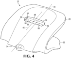
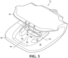
- the recess 34 may be a hole in leg 20 or as an offset surface around the boss at the forward portion ( Fig. 4-5 ).
- a hole 38 is provided through the leg 20 to receive lock 10.
- the hole 38 has a longitudinal axis 42 arranged transverse to a central axis 44 of the shroud 12.
- the hole 38 includes a back wall 48, a front wall 50 and opposing end walls 52. Hole 38 and recess 64 collectively define an opening 39 into which lock 10 is received in the hold position.
- the end walls 52 each includes retainers 54, 56 to interact with lock 10 and support the lock in release and hold positions.
- wear member 12 With the lock in the release position, wear member 12 can be installed on or removed from base 25 (i.e., the earth-working equipment). With lock 10 in the hold position, the wear member can be secured to the base 25.
- retainers 54, 56 are protrusions that extend inward from end walls 52. Nevertheless, retainers 54, 56 could have other constructions such as, e.g., being formed as one or more recesses that receive complementary projections on the lock or e.g., could be formed on the front and rear walls 48, 50.
- the retainers could be formed as a single retainer formation that permits mounting of the lock in both the release and hold positions.
- the ends of the lock could have two different formations to receive a single retainer in the hole to secure the lock in two positions. Accordingly, even though this disclosure generally refers to two retainers 54, 56 on each end wall, the number of retainers is not important. There could be one or more than two retainers provide to secure the lock in the release position and the hold position.
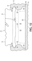
- the first or outer retainer 54 is, in this embodiment, in an outward position, i.e., proximate outer surface 57 of wear member 12 ( Figs 11 , 12 ).
- the second or inner retainer 56 is, in this embodiment, in an inward position, i.e., proximate inner surface 36 of wear member 12 ( Figs. 13 , 14B ).
- lock 10 is received in gap 66 such that both retainers 54, 56 function to secure lock 10 in the release position.
- the second retainer 56 has a substantially semi-cylindrical surface.
- the first retainer 54 includes a curvilinear portion 53 and a substantially straight portion 55 ( Fig. 14A ) to reduce its upward extension and the thickness of top leg 20.
- Second retainer 56 preferably has a fuller contact with the lock to resist the anticipated heavier loads applied during use such as during a digging operation.
- the retainers could have the same shape (e.g., both could be formed as a semi-cylindrical protrusion as shown for retainer 56), or either could have different shapes than shown.
- the first retainer 54 may be continuous or discontinuous as illustrated ( Figs. 4-5 ), i.e., with a central gap 58 to provide access to enable fines to be more readily cleaned from opening 39.
- the second retainer 56 may also, or instead, be discontinuous.
- the first retainer 54 protrudes into hole 38 a shorter distance than the second protrusion 56, although this is not necessary.
- a first or medial pocket or gap 66 is located between the retainers 54, 56.
- a second or inward pocket or gap 68 is located inward of retainer 56 (i.e., between retainer 56 and inner surface 36).
- the pockets 66, 68 may include straight, curvilinear or other surfaces ( Figs. 12 , 14A , 14B ).
- the second protrusion 56 may be made to include a substantially semi-cylindrical profile to provide a robust contact surface to contact the lock 10 in both an outward and an inward direction.
- the lock 10 can be fitted within opening 39 to hold wear member 12 to the earth-working equipment 14.
- lock 10 is secured to second retainers 56 to oppose bearing face 40 of boss 26 and bearing surface 48 in hole 38 to hold the wear member 12 in place; i.e., with lock 10 in the hold position in opening 39, the wear member cannot be pulled from the lip 16 ( Fig. 3 ).
- the lock 10 can be held at two different places on the wear member 12.
- the two places may be defined as a release position (e.g., where the lock is placed for shipping, storage and/or installation) ( Fig. 12 ), and a hold position (e.g., where the lock can secure the wear member to the base) ( Fig. 14B ).
- the release position is where the bottom lobe 107 of the lock 10 is positioned between the inner retainer 56 and the outer retainer 54.
- the release position may also be defined as the inner lobes 107 are fitted into complementarily sized and shaped pockets 66. The pockets 66 may tend to "grip" the inner lobe 107. Other constructions are possible.
- the lock may also have two different configurations: an unlocked or folded configuration where the lock can be installed or removed from the hole 38 and retainers 54, 56, and a locked or unfolded configuration where the lock can engage the retainers 54, 56 in hole 38.
- the lock may be installed in the release position of the hole at the time of manufacture, i.e., wherein one lock is securely mated with one wear member for shipping, storage and/or installation.
- the shroud can be installed on the base 25, i.e. installed onto the earth-working machine without modifying the lock in any way.
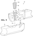
- Relative pivoting or hinging of the two bodies 70, 72 may be accomplished with a hinge mechanism 82.
- the hinge mechanism 82 includes an integral post 84 projecting from the first contact face 76 of the first body 70.
- the second contact face 78 includes a complementary hole 86 sized and located to receive the post 84 thereby pivotally coupling the first and second bodies 70, 72 together in an assembly 99 for limited movement about axis 74 ( Figs 6-10 ).
- the pivot axis 74 is generally parallel to longitudinal axis 44 of wear member 12 and perpendicular to the contact faces 76, 78.
- the pivot connection could have other constructions.
- the hinge mechanism 82 could have other constructions including, for example, forming each body with a hole for receiving a pivot pin secured in place by retaining rings or the like.
- Insert 100 When insert 100 is removed, bodies 70, 72 can pivot about axis 74 from the locked configuration to the unlocked configuration ( Fig. 14A ). Insert 100 can have many different forms and be received in other openings provided in one or both components. For example, it could be unthreaded and secured by other means, it could have other shapes, and/or be inserted in other positions and/or at other locations. Insert 100 simply needs to secure lock components 70, 72 in its locked configuration.
- the insert 100 contacts a progressively smaller inner circumference in both channels 90, 92.
- the radii of the insert 100 and channels 90, 92 in a fully seated position are generally the same.
- the radius of curvature for one channel is smaller than the radius of the insert in corresponding positions when fully seated, while the curvature of the other channel generally matches or is larger than the insert.
- the channel with the smaller radius is unthreaded. The threaded channel, then, maintains a single line contact while the non-threaded channel maintains a double line of contact.
- each body 70, 72 having a tab 142 at one end and a retention slot 144 at the opposite end, though other interlock constructions are possible ( Fig. 7 ).
- the tab 142 may be slideable into the slot 144 in the same hinging motion about the pivot axis 74 as the hinging and unhinging, or straightening, motion of the lock bodies 70, 72 described herein.
- Each tab 142 may extend substantially radially from the pivot axis 74, and the inner opposed walls 146 of each retention slot 144 (when in the closed extended position) may extend in close coplanar proximity to outside opposite surfaces of the tab 142.
- the tab 142 surfaces and the retention walls may be angled slightly from parallel to provide a radial draft to provide rapid and unobstructed separation of the adjacent surfaces when the lock bodies 70, 72 are pivoted open.
- Tab ends and/or end walls of the slots 144 may also define a radial draft to also, or instead, provide rapid and unobstructed separation of the adjacent surfaces when the lock bodies 70, 72 are pivoted open.
- Each lock body 70, 72 can be transversely flexed away from a longitudinal axis 112 of the lock 10 by the insert 100, imparting a pre-load into the lock 10.
- the pre-loaded lock bodies 70, 72 in turn provide transverse retention forces 150 from opposite sides of the slip plane 80 to resist ejection of the insert 100.
- the resultant force components are generally perpendicular to the slip plane 80 and transverse to the longitudinal axis ( Figs. 6-8 ).
- various surfaces for example, the interlocks 140 and the pivot pin 84 increase the stability of the assembled lock components 70, 72 even without the insert 100 in place.
- the interlocks 140 and the pivot pin 84 provide constraining surfaces that limit the degrees of freedom of relative movement between the lock components 70, 72, except for the relative pivoting, or hinging, movement.
- the interlocks 140 resist relative lateral movement of the lock components.
- the pivot pin 84 extends across the contact faces 76, 78 in a lateral direction, and is accordingly disposed to resist relative longitudinal movement between the lock components 70, 72. Accordingly, even without the insert 100 in place the lock 10 is easy to handle, move, and otherwise manipulate. This may be particularly useful to the operator.
- the insert 100 may be disposed to prevent a relative pivoting or hinging between the lock components 70, 72. Consequently, the forces on the insert are relatively limited to resisting relative pivoting tending to protect the insert from deformation, and/or ejection.
- the interlocks 140 and the pivot pin 84 tend to hold the lock in place, and resist various loads that may be placed on it.
- a bending force 170 may impart tensile stress on one side of the central axis 112 and compressive forces on the other side. The bending forces will tend to pull the tab 142 on the side in tension out of the mating slot 144.
- the outer surface of the pivot pin 84 in contact with inside walls of the complementary hole 86 will resist relative longitudinal movement of the lock components 70, 72, adding to the strength and stability of the lock.
- the pivot axis 74 is preferably substantially perpendicular to, and proximate with, the central axis 101 of the insert 100.
- any relative pivoting or hinging of the lock components 70, 72 about axis 74 results in minimal displacement of passage 102 parallel to central axis 101 of the insert 100. Consequently, axial forces on the insert 100 directed to resist hinging is minimized reducing the potential for ejection or deformation.
- the interlock includes concentric walls 282, 284 able to slide relative one another to permit a relative pivoting motion of the lock bodies 270, 272 about pivot axis 274 ( Figs 16-17 ).
- Each body can include a tab or protrusion and a slot that interlock in a tongue and groove configuration.
- Lock assembly 200 includes tabs 292 and 294 defining walls 292A and 294A. Spaced from the tabs, the lock assembly can include slots 296 and 298 defining walls 296A and 298A. These walls 292, 294, 296, 298 of the tabs and slots have generally corresponding shapes and are shown in Fig. 17 as being curved and concentric about the pivot axis.
- End walls 87, 88 of the lock clear end walls 52 of the opening 38 so that the lock can be withdrawn from the wear member 12.
- At least one body 70, 72 (and preferably both to enable removal from either direction) is provided with a grip 120 to facilitate pivoting of the bodies and pulling the lock from the opening.
- grips 120 are formed as inclined cavities to receive a removal tool 122; although other forms of grips could be used.
- Each body 70, 72 can also include a depression 124 spaced from grip 120 to stably support a fulcrum 126 of tool 122.
- a gripping end 128 of tool 122 fits into cavity, or grip 120 on body 70 (or 72) with fulcrum 126 resting in one depression 124.
- the lever 130 of tool 122 is pushed downward to pull the middle of lock 10 upward such that the bodies 70, 72 pivot about hinge mechanism 82. In this position, the lock 10 can be pulled out of opening 38 with tool 122 to permit removal of the shroud from the equipment.
- First body 370 and second body 372 include tabs 392 and 394 and slots 396 and 398 respectively that will engage in a tongue and groove configuration on assembly of the bodies.
- First body 370 has a contact or inner face 376 and second body 372 has contact or inner face 378.
- Contact face 376 preferably has a generally hemispherical recess 382 and an opening 380A. Above and below the hemispherical recess are preferably curved bearing surfaces 384A and 386A.
- Contact face 378 includes a laterally-projecting threaded collar or protrusion 374 provided with a pin 380.
- the collar has an opening or passage 375 extending through it along a passage axis that is generally parallel to the contact faces and generally perpendicular to the pivot axis of the lock.
- the passage 375 is provided with threads 375A in the wall of the opening.
- Second body 372 includes a recess 382 to receive collar 374, and a hole 380A to receive pin 380. Above and below the collar are curved bearing surfaces 384B and 386B.
- Fig. 20 is an exploded view of the lock 350.
- the bodies 370 and 372 are assembled so that the collar 374 with the threaded passage 375 and pin 380 are received by recess 382 and hole 380A respectively.
- the collar and the recess have complementary shapes to allow the lock bodies to pivot relative to each other about the pin and hole defining a pivot axis 274 with limited binding.
- the exterior of collar 374 and recess 382 are preferably spherical segments, though other shapes are possible.
- Tabs 392 and 394 are received by slots 396 and 398 as the bodies pivot to an extended position. Other shapes can be used for the surfaces of the collar and recess, and the collar and recess are not necessarily mating shapes.
- the collar is symmetrical about a pivot axis and allows pivotal movement of the bodies once assembled.
- Threaded insert 300 With the lock in the extended position, the bearing surfaces 384A and 384B adjacent each other form a single circular upper bearing surface 384. Similarly bearing surface 386A and 386B adjacent each other form lower circular bearing surface 386. The bearing surfaces, though, need not form a complete circle.
- Threaded insert 300 With the bodies 370, 372 in the extended position, threaded insert 300 is received in threaded opening 375. Threaded insert 300 preferably includes a head 300A with a recess 300B to receive a torque tool (not shown) such has a hex driver, though other tool-receiving formations could be used.
- insert 300 is shown with a radially expanded head, the head can simply be the trailing end of the shaft, i.e., a continuation of the shaft with no radial extension. Also, while a threaded insert 300 and threaded opening 375 are preferred, they could each be non-threaded with other means (e.g., a latch) for retaining the insert in the opening.
- a threaded insert 300 and threaded opening 375 are preferred, they could each be non-threaded with other means (e.g., a latch) for retaining the insert in the opening.
- Threaded insert 300 can optionally include a biased latching tooth 308 extending from the insert.
- the tooth can engage a corresponding outer pocket or recess 310 in the threaded opening 375 of the collar.
- the tooth engaging the recess can limit rotation of the insert below a set level of applied torque and prevent the insert from inadvertent loss of the insert from the lock.
- the interlocking tooth and recess can define a stop for the fully installed position.
- a shaft of the insert 300 preferably includes an upper bearing surface 304, a lower bearing surface 306, and threads 302 between the two.
- the upper and lower bearing surfaces 304 and 306 are adjacent to or bearing on bearing surfaces 384 and 386 respectively.
- the fitting of the upper and lower bearing surfaces 304, 306 of the insert 300 with the bearing surfaces 384, 386 of the bodies 370, 372 limits pivoting movement of the bodies 370 and 372 about pivot axis 274.
- the lock 350 is received in the opening of the wear member in a similar way to previous locks described above and engages the retaining structure of the opening in a similar way.
- the threaded opening can include complete threads that continue around the circumference of the opening. Alternatively, the opening can include thread portions or ridges in the opening to engage threads 302 of the insert 300.
- Lock bodies 370, 372 and insert 300 are shown with upper and lower bearing surfaces but other constructions are possible.
- the insert can have a head 300A, threads 302 and a lower bearing surface 306 without the upper bearing surface 304.
- the head can act as the upper bearing surfaces in some constructions.
- the lock has only threads and a lower bearing surface to bear on the insert 300 without an upper bearing surface.
- the lock has threads and an upper bearing surface to bear on the insert without a lower bearing surface.
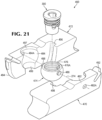
- Fig. 21 shows an alternative construction of a lock 450 that includes bodies 470 and 472 with similar features to locks described above.
- First body 470 and second body 472 include tabs 492 and 494 and slots 496 and 498 respectively that will engage in a tongue and groove configuration on assembly of the lock bodies.
- the bodies each preferably have a hemispherical recess 482 and 484 each with an opening 482A and 484A.
- a collar 474 separate from the bodies 470, 472 is received in recesses 482, 484.
- the collar 474 is provided with an opening or passage 476 that passes through the collar and is provided with threads 476A in the walls of the passage.
- the collar has pins 486 and 488 on opposite sides.
- Lock 450 is assembled by receiving collar 474 in recesses 482 and 484 with pins 486 and 488 in openings 482A and 484A. Lock bodies 470 and 472 then pivot about the pins and openings to an extended position with tabs 492 and 494 received by slots 496 and 498. In the extended position, upper circular bearing surface 497 is above collar 474. Lower circular bearing surface 499 is below collar 474. Insert 300 is received in the threaded collar and bearing surfaces 302 and 304 bear on or are adjacent to bearing surfaces 497 and 499. When installed, the insert limits pivotal movement of bodies 470 and 472 in relation to each other. Other embodiments are possible with only an upper bearing surface or only a lower bearing surface to bear on insert 300.
- the collar and recess are not necessarily mating shapes.
- the collar is symmetrical about a pivot axis and allows pivotal movement of the bodies once assembled.
- Fig. 22 is a lock 550 with a middle structure 502 similar to locks described above, i.e., for example with a tongue and groove structure and an insert that limits pivotal movement.
- Lock 550 has beveled ends 502 and 504 that converge extending upwards.
- Lock 550 can be received in an opening of a wear member with a corresponding construction.
- wear members are described in US7536811 . Any of the locks described herein could be formed with beveled ends (or other ends) to fit into different wear members and secure the wear members to the earth working equipment.
- the retainers may be threaded rods or threaded wedges in any of the disclosed embodiments.
- the retainers may have considerably different constructions and include shifting plates, detents, latches, etc.
- the pivot axis or hinge may be defined in other ways that permit the desired movement of the bodies. Folding of the locking component could also be achieved by other means.
- various other embodiments as well as many changes and alterations may be made without departing from the scope of protection as defined by the appended claims.
Landscapes
- Engineering & Computer Science (AREA)
- Mining & Mineral Resources (AREA)
- Civil Engineering (AREA)
- General Engineering & Computer Science (AREA)
- Structural Engineering (AREA)
- Mechanical Engineering (AREA)
- Component Parts Of Construction Machinery (AREA)
- Earth Drilling (AREA)
- Shovels (AREA)
- Pivots And Pivotal Connections (AREA)
- Ladders (AREA)
- Accommodation For Nursing Or Treatment Tables (AREA)
- Connection Of Plates (AREA)
- Automatic Assembly (AREA)
- Underground Structures, Protecting, Testing And Restoring Foundations (AREA)
- Prostheses (AREA)
- Revetment (AREA)
- Slide Fasteners (AREA)
- Pressure Welding/Diffusion-Bonding (AREA)
Priority Applications (1)
| Application Number | Priority Date | Filing Date | Title |
|---|---|---|---|
| RS20250829A RS67120B1 (sr) | 2016-05-05 | 2017-05-05 | Brava i postupak učvršćivanja |
Applications Claiming Priority (3)
| Application Number | Priority Date | Filing Date | Title |
|---|---|---|---|
| US201662332286P | 2016-05-05 | 2016-05-05 | |
| EP17793499.9A EP3452664B1 (en) | 2016-05-05 | 2017-05-05 | A wear part for earth working equipment |
| PCT/US2017/031398 WO2017193067A1 (en) | 2016-05-05 | 2017-05-05 | A wear part for earth working equipment |
Related Parent Applications (3)
| Application Number | Title | Priority Date | Filing Date |
|---|---|---|---|
| EP17793499.9A Division EP3452664B1 (en) | 2016-05-05 | 2017-05-05 | A wear part for earth working equipment |
| EP17793499.9A Division-Into EP3452664B1 (en) | 2016-05-05 | 2017-05-05 | A wear part for earth working equipment |
| PCT/US2017/031398 Previously-Filed-Application WO2017193067A1 (en) | 2016-05-05 | 2017-05-05 | A wear part for earth working equipment |
Publications (3)
| Publication Number | Publication Date |
|---|---|
| EP4015716A1 EP4015716A1 (en) | 2022-06-22 |
| EP4015716B1 true EP4015716B1 (en) | 2025-07-02 |
| EP4015716C0 EP4015716C0 (en) | 2025-07-02 |
Family
ID=60203510
Family Applications (2)
| Application Number | Title | Priority Date | Filing Date |
|---|---|---|---|
| EP21205142.9A Active EP4015716B1 (en) | 2016-05-05 | 2017-05-05 | Lock and securing method |
| EP17793499.9A Active EP3452664B1 (en) | 2016-05-05 | 2017-05-05 | A wear part for earth working equipment |
Family Applications After (1)
| Application Number | Title | Priority Date | Filing Date |
|---|---|---|---|
| EP17793499.9A Active EP3452664B1 (en) | 2016-05-05 | 2017-05-05 | A wear part for earth working equipment |
Country Status (26)
| Country | Link |
|---|---|
| US (3) | US10612214B2 (da) |
| EP (2) | EP4015716B1 (da) |
| JP (3) | JP2019515161A (da) |
| KR (2) | KR102448824B1 (da) |
| CN (2) | CN109072592B (da) |
| AR (1) | AR108392A1 (da) |
| AU (4) | AU2017261340C1 (da) |
| BR (3) | BR122020008469B1 (da) |
| CA (3) | CA3220905A1 (da) |
| CL (1) | CL2018003119A1 (da) |
| CO (1) | CO2018011784A2 (da) |
| DK (1) | DK3452664T3 (da) |
| EA (1) | EA201892623A1 (da) |
| ES (2) | ES3041440T3 (da) |
| LT (1) | LT3452664T (da) |
| MX (2) | MX2018013528A (da) |
| MY (1) | MY195379A (da) |
| NZ (2) | NZ748535A (da) |
| PE (2) | PE20181870A1 (da) |
| PL (1) | PL3452664T3 (da) |
| RS (2) | RS62898B1 (da) |
| SI (1) | SI3452664T1 (da) |
| TW (2) | TW202309378A (da) |
| UA (1) | UA127599C2 (da) |
| WO (1) | WO2017193067A1 (da) |
| ZA (1) | ZA201807356B (da) |
Families Citing this family (18)
| Publication number | Priority date | Publication date | Assignee | Title |
|---|---|---|---|---|
| TW202309378A (zh) * | 2016-05-05 | 2023-03-01 | 美商艾斯克集團有限責任公司 | 用於大地工作設備之磨損構件及磨損總成 |
| US10538900B2 (en) * | 2017-11-30 | 2020-01-21 | Caterpillar Inc. | Wear member for a work tool |
| EP3775410B1 (en) * | 2018-03-30 | 2025-05-07 | ESCO Group LLC | Wear member, edge and process of installation |
| USD922447S1 (en) | 2018-11-06 | 2021-06-15 | Caterpillar Inc. | Retention component |
| AR119029A1 (es) | 2019-05-31 | 2021-11-17 | Esco Group Llc | Monitoreo de productos de corte para equipos de movimiento de tierra |
| JP2022537174A (ja) | 2019-06-17 | 2022-08-24 | エスコ・グループ・エルエルシー | 地面係合製品の監視 |
| AU2020316238B2 (en) * | 2019-07-22 | 2026-01-22 | 2Mt Mining Products Pty Ltd | Retainer systems |
| PL4111003T3 (pl) * | 2020-02-27 | 2024-06-10 | Sandvik Mining And Construction Australia (Production/Supply) Pty Ltd. | Zespół mocujący do osłony narzędzia do prac ziemnych |
| MX2023000689A (es) * | 2020-07-17 | 2023-02-13 | Metalogenia Research & Tech Sl | Adaptador y elemento de desgaste con un pasador dispuesto en un punto de bajos esfuerzos. |
| CN116829792A (zh) * | 2021-01-29 | 2023-09-29 | 爱斯科集团有限责任公司 | 用于土工设备的磨损组件、挖掘边缘和插入件 |
| US12018465B2 (en) * | 2021-02-17 | 2024-06-25 | Black Cat Wear Parts, Ltd. | Heel shroud for material moving implement and associated methods |
| US20220325505A1 (en) * | 2021-04-12 | 2022-10-13 | Esco Group Llc | Wear assembly |
| CA3221630A1 (en) * | 2021-06-09 | 2022-12-15 | Christopher David EDMONDS | Wear assembly |
| US20230323640A1 (en) * | 2022-04-11 | 2023-10-12 | Hensley Industries, Inc. | Excavating assembly with pivot fastening system |
| NL2031780B1 (nl) * | 2022-05-04 | 2023-11-14 | Dredge Yard Dmcc | Tand voor een baggerwerktuig, tandlichaam voor gebruik in de tand en baggerwerktuig met de tand |
| WO2025136617A1 (en) * | 2023-12-22 | 2025-06-26 | Esco Group Llc | Lock, wear member and wear assembly having a lock |
| WO2026055266A2 (en) | 2024-09-06 | 2026-03-12 | Esco Group Llc | Wear member, edge and process of installation |
| WO2026064277A1 (en) | 2024-09-17 | 2026-03-26 | Esco Group Llc | Shroud support structure, shroud and shroud mounting system |
Family Cites Families (73)
| Publication number | Priority date | Publication date | Assignee | Title |
|---|---|---|---|---|
| US1384701A (en) | 1918-11-04 | 1921-07-12 | William F Mcmonegal | Shovel-tooth |
| US2891333A (en) | 1954-09-10 | 1959-06-23 | Lesher W Van Buskirk | Digging teeth for excavating, dippers, etc. |
| US2904909A (en) | 1955-07-14 | 1959-09-22 | American Brake Shoe Co | Dipper teeth |
| US2951300A (en) | 1956-09-19 | 1960-09-06 | American Brake Shoe Co | Dipper teeth |
| US2987838A (en) | 1957-08-05 | 1961-06-13 | Elton Stratton | Excavating tooth |
| US3137352A (en) | 1961-08-28 | 1964-06-16 | Petersen Engineering Co Inc | Shank protector for earth digging tool |
| FR2381137A1 (fr) | 1977-02-18 | 1978-09-15 | Esco Corp | Dent excavatrice pour godet de chargeuse sur pneumatiques ou analogue |
| AU76255S (en) | 1978-10-19 | 1979-01-31 | Farmland Pty Ltd | adaptor for an agricultural tine |
| US4501079A (en) | 1983-08-24 | 1985-02-26 | Esco Corporation | Two piece cutting edge construction |
| AU91870S (en) | 1984-06-29 | 1986-05-08 | Farmland Pty Ltd | Digging point |
| USD326459S (en) | 1989-11-16 | 1992-05-26 | Anderson Kevin M | Press plate |
| USD329243S (en) | 1990-03-20 | 1992-09-08 | G. H. Hensley Industries, Inc. | Excavator tooth |
| USD328466S (en) | 1990-03-20 | 1992-08-04 | G. H. Hensley Industries, Inc. | Excavator tooth |
| US5172501A (en) | 1990-06-21 | 1992-12-22 | Pippins Sherlock K | Tooth assembly for excavating apparatus |
| US5241765A (en) * | 1991-01-17 | 1993-09-07 | Esco Corporation | Lock assembly for wearable structure |
| US5088214A (en) | 1991-01-17 | 1992-02-18 | Esco Corporation | Excavator wear edge |
| JP4021527B2 (ja) * | 1997-10-02 | 2007-12-12 | 保夫 鈴木 | ショベル機械のバケット本体に付設するアダプタ部材とツース部材との固定手段 |
| USD420014S (en) | 1998-03-02 | 2000-02-01 | Componenta Wear Parts Ab | Tooth system |
| US6145224A (en) | 1998-11-06 | 2000-11-14 | Caterpillar Inc. | Ground engaging tools for earthworking implements and retainer therefor |
| USD435567S (en) | 1999-10-21 | 2000-12-26 | H&L Tooth Co. | Digging tooth |
| USD436116S1 (en) | 1999-10-21 | 2001-01-09 | H&L Tooth Co. | Digging tooth |
| USD446223S1 (en) | 2000-03-30 | 2001-08-07 | Gerald D. Edwards | Tooth device for use with powered diggers |
| US7219454B2 (en) | 2000-08-04 | 2007-05-22 | Shark Abrasion Systems Pty. Ltd. | Attachment system |
| US6993861B2 (en) | 2001-07-06 | 2006-02-07 | Esco Corporation | Coupling for excavating wear part |
| US20030007831A1 (en) * | 2001-07-06 | 2003-01-09 | Lian Aaron B. | Lock with internal retainer |
| KR100992643B1 (ko) | 2001-07-06 | 2010-11-05 | 에스코 코포레이션 | 굴착 마모 부품용 커플링 |
| AUPS134802A0 (en) | 2002-03-26 | 2002-05-09 | Shark Abrasion Systems Pty Ltd | Attachment system |
| AU2003275124B2 (en) * | 2002-09-19 | 2010-09-23 | Esco Corporation | Coupling arrangement |
| EP1852557B1 (en) * | 2002-09-19 | 2010-07-21 | Esco Corporation | Wear assembly and lock for an excavating bucket |
| US7171771B2 (en) | 2003-04-30 | 2007-02-06 | Esco Corporation | Releasable coupling assembly |
| USD552632S1 (en) | 2004-02-10 | 2007-10-09 | Italricambi Srl | Tooth assembly for buckets |
| USD546350S1 (en) | 2004-02-10 | 2007-07-10 | Italricambi Srl | Tooth assembly for buckets |
| US7356811B2 (en) | 2004-07-08 | 2008-04-08 | International Business Machines Corporation | Method and apparatus for referencing a constant pool in a java virtual machine |
| USD560232S1 (en) | 2005-05-30 | 2008-01-22 | Italricambi Spa | Tooth assembly for buckets |
| MY149408A (en) | 2005-08-30 | 2013-08-30 | Esco Corp | Wear assembly for excavating machines |
| CN104727374B (zh) * | 2006-03-30 | 2017-09-12 | 爱斯科公司 | 用于挖掘设备的磨耗构件及磨耗组件 |
| PE20080597A1 (es) * | 2006-04-24 | 2008-05-17 | Esco Corp | Montaje de desgaste |
| NZ573033A (en) * | 2006-06-16 | 2011-10-28 | Esco Corp | Lock with foldable element and a retainer for securing wear member to earth-moving equipment |
| CA2788482C (en) | 2006-08-16 | 2015-09-29 | Caterpillar Inc. | Ground engaging tool system |
| NZ575959A (en) * | 2006-10-24 | 2011-06-30 | Esco Corp | Wear assembly for an excavating bucket |
| US7526886B2 (en) | 2006-10-24 | 2009-05-05 | Esco Corporation | Wear assembly for an excavating bucket |
| US7874086B2 (en) | 2007-04-24 | 2011-01-25 | Esco Corporation | Lock assembly for securing a wear member to earth-working equipment |
| CA2745979A1 (en) | 2008-12-10 | 2010-06-17 | Cqms Pty Ltd | A lock for an excavator wear assembly |
| USD634605S1 (en) | 2010-05-24 | 2011-03-22 | Cqms Pty Ltd | Locking pin assembly for an excavator wear member |
| WO2011097689A1 (en) | 2010-02-15 | 2011-08-18 | Cutting Edges Equipment Parts Pty Limited | A wear assembly and lock mechanism |
| JO3763B1 (ar) * | 2010-04-20 | 2021-01-31 | Esco Group Llc | تجميعة إقتران مع أداة تعليق مُدَعَّمة |
| JP5210415B2 (ja) | 2011-05-09 | 2013-06-12 | 株式会社小松製作所 | 建設機械のバケットツース |
| JP2012246735A (ja) | 2011-05-31 | 2012-12-13 | Higuchi Seisakusho Co Ltd | ショベル系掘削機用ツース部材及びそのバケット |
| UA108940C2 (uk) * | 2011-07-05 | 2015-06-25 | Утримуючий пристрій, утримуюча система між охоплюючим компонентом і охоплюваним компонентом, охоплюючий компонент і охоплюваний компонент для екскаваторів і їм подібних машин | |
| JO3726B1 (ar) * | 2011-07-14 | 2021-01-31 | Esco Group Llc | مجموعة بطانه |
| USD707264S1 (en) | 2011-10-07 | 2014-06-17 | Caterpillar Inc. | Adapter for a ground engaging machine implement |
| EP2783052B1 (en) * | 2011-11-23 | 2021-01-06 | ESCO Group LLC | Wear assembly |
| US8978277B2 (en) * | 2012-06-06 | 2015-03-17 | Raptor Mining Products Inc. | Dual thread hammerless wedge and spool |
| US9540796B2 (en) | 2012-09-04 | 2017-01-10 | Sandvik Intellectual Property Ab | Ground engaging tool mechanical attachment |
| AU347850S (en) | 2013-02-12 | 2013-04-02 | Cqms Pty Ltd | An excavator wear member |
| US9309651B2 (en) * | 2013-03-15 | 2016-04-12 | Caterpillar Inc. | Retainer systems for ground engaging tools |
| CN105229243B (zh) * | 2013-03-18 | 2018-11-20 | 埃斯科集团有限责任公司 | 用于土方作业辊的磨损帽 |
| JOP20140215B1 (ar) * | 2013-07-10 | 2023-03-28 | Esco Group Llc | موصل لتسهيل رفع الأجزاء البالية |
| USD728636S1 (en) | 2013-08-01 | 2015-05-05 | Caterpillar Inc. | Coupler and tip for a ground engaging machine implement |
| USD728635S1 (en) | 2013-08-01 | 2015-05-05 | Caterpillar Inc. | Coupler for a ground engaging machine implement |
| CN103452163A (zh) * | 2013-09-12 | 2013-12-18 | 太原重工股份有限公司 | 挖掘机及其斗齿连接组件 |
| WO2015089565A1 (en) * | 2013-12-20 | 2015-06-25 | Bradken Resources Pty Limited | Lock assembly for a wear member |
| US9518379B2 (en) * | 2014-02-28 | 2016-12-13 | Caterpillar Inc. | Shroud retention system having replaceable lug insert |
| CN104405008B (zh) * | 2014-12-16 | 2016-08-31 | 广西柳工机械股份有限公司 | 斗齿组件 |
| USD769946S1 (en) | 2015-04-17 | 2016-10-25 | Caterpillar Inc. | Lip for ground engaging machine implement |
| FR3035889B1 (fr) * | 2015-05-05 | 2017-06-16 | Safe Metal | Dispositif, systeme et procede de protection d'une arete de godet |
| AU2016203773B2 (en) | 2015-06-11 | 2021-06-24 | Bradken Resources Pty Limited | Lip & shroud assembly |
| USD775240S1 (en) | 2015-08-12 | 2016-12-27 | Caterpillar Inc. | Tip for a ground engaging machine implement |
| US9938695B2 (en) * | 2015-09-10 | 2018-04-10 | Caterpillar Inc. | Shroud retention system for a work tool |
| TW202309378A (zh) * | 2016-05-05 | 2023-03-01 | 美商艾斯克集團有限責任公司 | 用於大地工作設備之磨損構件及磨損總成 |
| USD797163S1 (en) | 2016-07-21 | 2017-09-12 | Caterpillar Inc. | Lip shroud for ground engaging machine implement and/or digital representation thereof |
| USD806141S1 (en) | 2016-12-15 | 2017-12-26 | Caterpillar Inc. | Adapter for a ground engaging machine implement |
| USD837834S1 (en) * | 2017-05-05 | 2019-01-08 | Esco Group Llc | Wear part for earth working equipment |
-
2017
- 2017-05-05 TW TW111143393A patent/TW202309378A/zh unknown
- 2017-05-05 NZ NZ748535A patent/NZ748535A/en not_active IP Right Cessation
- 2017-05-05 TW TW106114966A patent/TWI781931B/zh not_active IP Right Cessation
- 2017-05-05 RS RS20220037A patent/RS62898B1/sr unknown
- 2017-05-05 EA EA201892623A patent/EA201892623A1/ru unknown
- 2017-05-05 CN CN201780027699.2A patent/CN109072592B/zh active Active
- 2017-05-05 ES ES21205142T patent/ES3041440T3/es active Active
- 2017-05-05 DK DK17793499.9T patent/DK3452664T3/da active
- 2017-05-05 LT LTEPPCT/US2017/031398T patent/LT3452664T/lt unknown
- 2017-05-05 PL PL17793499T patent/PL3452664T3/pl unknown
- 2017-05-05 AU AU2017261340A patent/AU2017261340C1/en active Active
- 2017-05-05 EP EP21205142.9A patent/EP4015716B1/en active Active
- 2017-05-05 NZ NZ781604A patent/NZ781604A/en not_active IP Right Cessation
- 2017-05-05 BR BR122020008469-3A patent/BR122020008469B1/pt active IP Right Grant
- 2017-05-05 WO PCT/US2017/031398 patent/WO2017193067A1/en not_active Ceased
- 2017-05-05 PE PE2018002305A patent/PE20181870A1/es unknown
- 2017-05-05 BR BR122020008432-4A patent/BR122020008432B1/pt active IP Right Grant
- 2017-05-05 EP EP17793499.9A patent/EP3452664B1/en active Active
- 2017-05-05 KR KR1020187033568A patent/KR102448824B1/ko active Active
- 2017-05-05 CA CA3220905A patent/CA3220905A1/en active Pending
- 2017-05-05 SI SI201731076T patent/SI3452664T1/sl unknown
- 2017-05-05 JP JP2018555977A patent/JP2019515161A/ja active Pending
- 2017-05-05 MX MX2018013528A patent/MX2018013528A/es unknown
- 2017-05-05 CA CA3220762A patent/CA3220762A1/en active Pending
- 2017-05-05 CA CA3022473A patent/CA3022473A1/en active Pending
- 2017-05-05 KR KR1020227033334A patent/KR102628615B1/ko active Active
- 2017-05-05 RS RS20250829A patent/RS67120B1/sr unknown
- 2017-05-05 ES ES17793499T patent/ES2903226T3/es active Active
- 2017-05-05 US US15/588,376 patent/US10612214B2/en active Active
- 2017-05-05 CN CN202110163804.3A patent/CN112982546B/zh active Active
- 2017-05-05 MY MYPI2018704012A patent/MY195379A/en unknown
- 2017-05-05 AR ARP170101180A patent/AR108392A1/es active IP Right Grant
- 2017-05-05 UA UAA201811041A patent/UA127599C2/uk unknown
- 2017-05-05 BR BR112018072566-8A patent/BR112018072566B1/pt active IP Right Grant
- 2017-05-05 PE PE2023001011A patent/PE20230924A1/es unknown
-
2018
- 2018-10-31 CL CL2018003119A patent/CL2018003119A1/es unknown
- 2018-10-31 CO CONC2018/0011784A patent/CO2018011784A2/es unknown
- 2018-11-02 ZA ZA2018/07356A patent/ZA201807356B/en unknown
- 2018-11-05 MX MX2022012420A patent/MX2022012420A/es unknown
-
2020
- 2020-03-30 US US16/834,818 patent/US11261585B2/en active Active
-
2022
- 2022-01-17 JP JP2022004988A patent/JP7274005B2/ja active Active
- 2022-01-17 JP JP2022004992A patent/JP7282931B2/ja active Active
- 2022-01-24 US US17/582,884 patent/US11970843B2/en active Active
-
2023
- 2023-01-12 AU AU2023200147A patent/AU2023200147B2/en active Active
- 2023-08-11 AU AU2023214388A patent/AU2023214388B2/en active Active
-
2025
- 2025-01-09 AU AU2025200143A patent/AU2025200143B2/en active Active
Also Published As
Similar Documents
| Publication | Publication Date | Title |
|---|---|---|
| AU2025200143B2 (en) | A wear part for earth working equipment | |
| EP2038486B1 (en) | Assembly of a wear part and a lock for securing the wear part to earth-working equipment | |
| OA18905A (en) | A wear part for earth working equipment. | |
| EA041755B1 (ru) | Изнашиваемая деталь для землеройного оборудования | |
| EA044619B1 (ru) | Изнашиваемая деталь для землеройного оборудования |
Legal Events
| Date | Code | Title | Description |
|---|---|---|---|
| PUAI | Public reference made under article 153(3) epc to a published international application that has entered the european phase |
Free format text: ORIGINAL CODE: 0009012 |
|
| STAA | Information on the status of an ep patent application or granted ep patent |
Free format text: STATUS: THE APPLICATION HAS BEEN PUBLISHED |
|
| AC | Divisional application: reference to earlier application |
Ref document number: 3452664 Country of ref document: EP Kind code of ref document: P |
|
| AK | Designated contracting states |
Kind code of ref document: A1 Designated state(s): AL AT BE BG CH CY CZ DE DK EE ES FI FR GB GR HR HU IE IS IT LI LT LU LV MC MK MT NL NO PL PT RO RS SE SI SK SM TR |
|
| STAA | Information on the status of an ep patent application or granted ep patent |
Free format text: STATUS: REQUEST FOR EXAMINATION WAS MADE |
|
| 17P | Request for examination filed |
Effective date: 20221221 |
|
| RBV | Designated contracting states (corrected) |
Designated state(s): AL AT BE BG CH CY CZ DE DK EE ES FI FR GB GR HR HU IE IS IT LI LT LU LV MC MK MT NL NO PL PT RO RS SE SI SK SM TR |
|
| STAA | Information on the status of an ep patent application or granted ep patent |
Free format text: STATUS: EXAMINATION IS IN PROGRESS |
|
| 17Q | First examination report despatched |
Effective date: 20240613 |
|
| 17Q | First examination report despatched |
Effective date: 20240625 |
|
| GRAP | Despatch of communication of intention to grant a patent |
Free format text: ORIGINAL CODE: EPIDOSNIGR1 |
|
| STAA | Information on the status of an ep patent application or granted ep patent |
Free format text: STATUS: GRANT OF PATENT IS INTENDED |
|
| INTG | Intention to grant announced |
Effective date: 20250226 |
|
| RIN1 | Information on inventor provided before grant (corrected) |
Inventor name: HANKLAND, JOEL S. Inventor name: ROSKA, MICHAEL B. Inventor name: ZENIER, SCOTT H. |
|
| RAP3 | Party data changed (applicant data changed or rights of an application transferred) |
Owner name: ESCO GROUP LLC |
|
| GRAS | Grant fee paid |
Free format text: ORIGINAL CODE: EPIDOSNIGR3 |
|
| GRAA | (expected) grant |
Free format text: ORIGINAL CODE: 0009210 |
|
| STAA | Information on the status of an ep patent application or granted ep patent |
Free format text: STATUS: THE PATENT HAS BEEN GRANTED |
|
| AC | Divisional application: reference to earlier application |
Ref document number: 3452664 Country of ref document: EP Kind code of ref document: P |
|
| AK | Designated contracting states |
Kind code of ref document: B1 Designated state(s): AL AT BE BG CH CY CZ DE DK EE ES FI FR GB GR HR HU IE IS IT LI LT LU LV MC MK MT NL NO PL PT RO RS SE SI SK SM TR |
|
| REG | Reference to a national code |
Ref country code: GB Ref legal event code: FG4D |
|
| REG | Reference to a national code |
Ref country code: CH Ref legal event code: EP |
|
| REG | Reference to a national code |
Ref country code: DE Ref legal event code: R096 Ref document number: 602017090388 Country of ref document: DE |
|
| REG | Reference to a national code |
Ref country code: IE Ref legal event code: FG4D |
|
| U01 | Request for unitary effect filed |
Effective date: 20250717 |
|
| U07 | Unitary effect registered |
Designated state(s): AT BE BG DE DK EE FI FR IT LT LU LV MT NL PT RO SE SI Effective date: 20250801 |
|
| REG | Reference to a national code |
Ref country code: ES Ref legal event code: FG2A Ref document number: 3041440 Country of ref document: ES Kind code of ref document: T3 Effective date: 20251112 |
|
| PG25 | Lapsed in a contracting state [announced via postgrant information from national office to epo] |
Ref country code: IS Free format text: LAPSE BECAUSE OF FAILURE TO SUBMIT A TRANSLATION OF THE DESCRIPTION OR TO PAY THE FEE WITHIN THE PRESCRIBED TIME-LIMIT Effective date: 20251102 |
|
| PG25 | Lapsed in a contracting state [announced via postgrant information from national office to epo] |
Ref country code: NO Free format text: LAPSE BECAUSE OF FAILURE TO SUBMIT A TRANSLATION OF THE DESCRIPTION OR TO PAY THE FEE WITHIN THE PRESCRIBED TIME-LIMIT Effective date: 20251002 |
|
| PG25 | Lapsed in a contracting state [announced via postgrant information from national office to epo] |
Ref country code: HR Free format text: LAPSE BECAUSE OF FAILURE TO SUBMIT A TRANSLATION OF THE DESCRIPTION OR TO PAY THE FEE WITHIN THE PRESCRIBED TIME-LIMIT Effective date: 20250702 |
|
| PG25 | Lapsed in a contracting state [announced via postgrant information from national office to epo] |
Ref country code: GR Free format text: LAPSE BECAUSE OF FAILURE TO SUBMIT A TRANSLATION OF THE DESCRIPTION OR TO PAY THE FEE WITHIN THE PRESCRIBED TIME-LIMIT Effective date: 20251003 |
|
| PG25 | Lapsed in a contracting state [announced via postgrant information from national office to epo] |
Ref country code: PL Free format text: LAPSE BECAUSE OF FAILURE TO SUBMIT A TRANSLATION OF THE DESCRIPTION OR TO PAY THE FEE WITHIN THE PRESCRIBED TIME-LIMIT Effective date: 20250702 |
|
| PG25 | Lapsed in a contracting state [announced via postgrant information from national office to epo] |
Ref country code: SM Free format text: LAPSE BECAUSE OF FAILURE TO SUBMIT A TRANSLATION OF THE DESCRIPTION OR TO PAY THE FEE WITHIN THE PRESCRIBED TIME-LIMIT Effective date: 20250702 |
|
| PGFP | Annual fee paid to national office [announced via postgrant information from national office to epo] |
Ref country code: GB Payment date: 20260327 Year of fee payment: 10 |
|
| PG25 | Lapsed in a contracting state [announced via postgrant information from national office to epo] |
Ref country code: SK Free format text: LAPSE BECAUSE OF FAILURE TO SUBMIT A TRANSLATION OF THE DESCRIPTION OR TO PAY THE FEE WITHIN THE PRESCRIBED TIME-LIMIT Effective date: 20250702 |