EP4015398B1 - Gestapelte satellitenanordnungen und zugehörige verfahren - Google Patents
Gestapelte satellitenanordnungen und zugehörige verfahren Download PDFInfo
- Publication number
- EP4015398B1 EP4015398B1 EP21214774.8A EP21214774A EP4015398B1 EP 4015398 B1 EP4015398 B1 EP 4015398B1 EP 21214774 A EP21214774 A EP 21214774A EP 4015398 B1 EP4015398 B1 EP 4015398B1
- Authority
- EP
- European Patent Office
- Prior art keywords
- satellite
- launch
- support structure
- satellite apparatus
- launch vehicle
- Prior art date
- Legal status (The legal status is an assumption and is not a legal conclusion. Google has not performed a legal analysis and makes no representation as to the accuracy of the status listed.)
- Active
Links
Images


Classifications
-
- B—PERFORMING OPERATIONS; TRANSPORTING
- B64—AIRCRAFT; AVIATION; COSMONAUTICS
- B64G—COSMONAUTICS; VEHICLES OR EQUIPMENT THEREFOR
- B64G1/00—Cosmonautic vehicles
- B64G1/002—Launch systems
- B64G1/005—Air launch
-
- B—PERFORMING OPERATIONS; TRANSPORTING
- B64—AIRCRAFT; AVIATION; COSMONAUTICS
- B64G—COSMONAUTICS; VEHICLES OR EQUIPMENT THEREFOR
- B64G1/00—Cosmonautic vehicles
- B64G1/10—Artificial satellites; Systems of such satellites; Interplanetary vehicles
-
- B—PERFORMING OPERATIONS; TRANSPORTING
- B64—AIRCRAFT; AVIATION; COSMONAUTICS
- B64G—COSMONAUTICS; VEHICLES OR EQUIPMENT THEREFOR
- B64G1/00—Cosmonautic vehicles
- B64G1/22—Parts of, or equipment specially adapted for fitting in or to, cosmonautic vehicles
-
- B—PERFORMING OPERATIONS; TRANSPORTING
- B64—AIRCRAFT; AVIATION; COSMONAUTICS
- B64G—COSMONAUTICS; VEHICLES OR EQUIPMENT THEREFOR
- B64G1/00—Cosmonautic vehicles
- B64G1/22—Parts of, or equipment specially adapted for fitting in or to, cosmonautic vehicles
- B64G1/223—Modular spacecraft systems
-
- B—PERFORMING OPERATIONS; TRANSPORTING
- B64—AIRCRAFT; AVIATION; COSMONAUTICS
- B64G—COSMONAUTICS; VEHICLES OR EQUIPMENT THEREFOR
- B64G1/00—Cosmonautic vehicles
- B64G1/22—Parts of, or equipment specially adapted for fitting in or to, cosmonautic vehicles
- B64G1/64—Systems for coupling or separating cosmonautic vehicles or parts thereof, e.g. docking arrangements
- B64G1/641—Interstage or payload connectors
- B64G1/643—Interstage or payload connectors for arranging multiple satellites in a single launcher
- B64G1/644—Interstage or payload connectors for arranging multiple satellites in a single launcher arranged for independent deployment
-
- B—PERFORMING OPERATIONS; TRANSPORTING
- B64—AIRCRAFT; AVIATION; COSMONAUTICS
- B64G—COSMONAUTICS; VEHICLES OR EQUIPMENT THEREFOR
- B64G1/00—Cosmonautic vehicles
- B64G1/22—Parts of, or equipment specially adapted for fitting in or to, cosmonautic vehicles
- B64G1/64—Systems for coupling or separating cosmonautic vehicles or parts thereof, e.g. docking arrangements
- B64G1/645—Separators
- B64G1/6457—Springs; Shape memory actuators
-
- B—PERFORMING OPERATIONS; TRANSPORTING
- B64—AIRCRAFT; AVIATION; COSMONAUTICS
- B64G—COSMONAUTICS; VEHICLES OR EQUIPMENT THEREFOR
- B64G1/00—Cosmonautic vehicles
- B64G1/002—Launch systems
Definitions
- US2018251238A1 in accordance with its abstract, states a three-axis spacecraft including a spacecraft body including first and second opposing radiator/equipment panels, first and second opposing mounting panels, an earth deck and a zenith deck.
- the zenith deck faces the Earth when the spacecraft is on orbit and the first and second mounting panels face an east and west direction relative to the Earth when the spacecraft is on orbit.
- the spacecraft further includes a mounting cylinder extending through the spacecraft body and out of the first and second mounting panels.
- a spacecraft may include an upper core structure or a lower core structure.
- the upper core structure may include an upper cylinder for supporting an upper spacecraft of a dual-manifest launch configuration.
- the lower core structure may include a lower cylinder for supporting a lower spacecraft with the upper cylinder mounted on top of the lower cylinder.
- the upper cylinder may have an upper cylinder inner diameter that may be substantially similar to the lower cylinder inner diameter.
- CN111532452A in accordance with its abstract, states a multi-star distributor force bearing structure which comprises a force bearing cylinder with a grid structure.
- the grid structure is a skin-free grid structure.
- a first inner reinforced n-shaped frame is arranged at a first end of the force bearing cylinder, and a second inner reinforced n-shaped frame is arranged at a second end of the force bearing cylinder; and at least one first satellite supporting table is arranged on an outer side arc surface of the first end of the force bearing cylinder, and at least one second satellite supporting table is arranged on the outer side arc surface of the second end of the force bearing cylinder.
- US10538347B1 in accordance with its abstract, states techniques for deploying a plurality of smallsats from a common launch vehicle where a structural arrangement provides a load path between an upper stage of the launch and the plurality of spacecraft. Each spacecraft is mechanically coupled with the launch vehicle upper stage only by the structural arrangement.
- the structural arrangement includes at least one trunk member that is approximately aligned with the longitudinal axis of the launch vehicle upper stage, a plurality of branch members, each branch member being attached to the trunk member and having at least a first end portion that is substantially outboard from the longitudinal axis; and a plurality of mechanical linkages, each linkage coupled at a first end with a first respective spacecraft and coupled at a second end with one of the plurality of branch members, the trunk member or a second respective spacecraft.
- US9796486B1 in accordance with its abstract, states a modular device for a spacecraft includes a propulsion system having a tank, a plenum, and a manifold, wherein the propulsion system is integrally formed with a structural frame of the spacecraft.
- a method of manufacturing the modular device is also discussed, the method including utilizing an additive manufacturing process to construct the propulsion system.
- the present disclosure provides systems, apparatus, and methods relating to satellite support structures and assemblies.
- a satellite assembly comprises: a launch vehicle having a launch axis; a first separation system; a first satellite apparatus; and a second satellite apparatus, wherein: the first satellite apparatus, comprises: a first housing including first and second opposing walls; and a first support structure (260) spanning the first and second opposing walls and enclosed by the first housing; an end portion of the first support structure is configured for connection to the launch vehicle by the first separation system; the second satellite apparatus comprises: a second housing including first and second opposing walls, and a second support structure spanning the first and second opposing walls of the second housing and enclosed by the second housing; a distal end portion of the first support structure in the first satellite apparatus is connected to a proximal end portion of the second support structure in the second satellite apparatus; wherein the first and second satellite apparatus are stacked perpendicular to the launch axis inside the launch vehicle.
- a method of deploying satellites from a launch vehicle may include stowing a plurality of satellites inside a launch vehicle by stacking the satellites horizontally relative to a vertical launch axis. The method may further include carrying the satellites to space in the launch vehicle, and separating the satellites from the launch vehicle horizontally relative to the vertical launch axis.
- a satellite in accordance with the present teachings may include a hollow central support structure and a housing.
- the central support structure may be the primary structure of the satellite, supporting the housing and connecting to a launch vehicle.
- the central support structure may span between first and second panels of the housing, and may be connected to the housing only by the first and second panels. Payload and operational equipment of the satellite may be supported by the housing.
- the central support structure may be additively manufactured, and include a cylindrical wall having an array of diamond-shaped apertures.
- the satellite may form part of a structural satellite launch configuration.
- a structural satellite launch configuration in accordance with the present teachings includes two satellites, each satellite having a central support structure that is the primary structure of the satellite.
- the central support structures of the two satellites may be connected to form a single beam structure, which may be mounted as a cantilever beam to a payload adaptor of a launch vehicle.
- the central support structures of the two satellites may define a core axis and the satellites may be mounted in the launch vehicle such that the core axis is perpendicular to a launch axis of the launch vehicle.
- a structural satellite launch configuration may include a plurality a pairs of connected satellites. Each pair of connected satellites may be connected to a central ring payload adaptor of the launch vehicle, extending radially outward from the ring adaptor.
- a structural satellite launch configuration may include one or more stacks of three or more satellites having connected central support structures, the one or more stacks being mounted to the launch vehicle such that a core axis defined by the central support structures is perpendicular to the launch axis of the launch vehicle.
- Each section describes selected exemplary satellites as well as related assemblies and/or methods.
- the examples in these sections are intended for illustration and should not be interpreted as limiting the entire scope of the present disclosure.
- Each section may include one or more distinct examples, and/or contextual or related information, function, and/or structure.
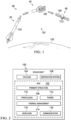
- illustrative satellite launch method 80 includes three phases: a launch phase 20, a separation or deployment phase 40, and an operation phase 60.
- Launch phase 20 may include transporting satellite 100 (alternatively, spacecraft 100) from a planetary body 120 such as Earth to outer space 122, using a launch vehicle 124.
- outer space may comprise a region beyond the Karman line.
- Deployment phase 40 may include separating satellite 100 from launch vehicle 124 once a desired location, trajectory and/or orbit has been achieved.
- Operation phase 60 may include preparation of satellite 100 for operation, such as establishing communication with a controller on planetary body 120, extending solar panels or instrument arms, and/or maneuvering to a desired orientation relative to the planetary body.
- the method may further include design, production, and/or in-service phases.
- a system integrator may include, without limitation, any number of aerospace manufacturers and major-system subcontractors; a third party may include, without limitation, any number of vendors, subcontractors, and suppliers; and an operator may be a telecommunications company, leasing company, military entity, service organization, and so on.
- satellite 100 may include a bus 102 with a plurality of satellite systems, a payload 104 and a separation system 106.
- the plurality of systems include one or more of a primary structure 108, a propulsion system 110, an electrical power system 112, a thermal management system 114, a radiation shielding system 116, and a communication system 118.
- Each system may comprise various subsystems, such as controllers, processors, actuators, effectors, motors, generators, etc., depending on the functionality involved. Any number of other systems may be included.
- an unmanned artificial satellite example is shown, the principles disclosed herein may be applied to other aerospace vehicles and technology, such as a launch vehicle, space station, crewed spacecraft, and/or interstellar probe.
- Apparatuses and methods shown or described herein may be employed during any one or more of the stages of the satellite launch method 80. Two or more satellites are stacked perpendicular to a launch axis of launch vehicle 124 during launch phase 20. Similarly, one or more examples of the apparatus or method realizations, or a combination thereof, may be utilized, for example and without limitation, while satellite 100 and/or launch vehicle 124 are in preparation prior to execution of launch method 80. Also, one or more examples of the apparatuses, methods, or combinations thereof may be utilized during deployment phase 40 for example, by deploying a satellite radially outward from launch vehicle 124, perpendicular to the launch axis of the vehicle.
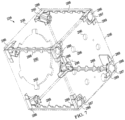
- Satellite assembly 200 is an example of a structural satellite launch configuration, as described above.
- the assembly includes a plurality of satellite stacks 210.
- Each stack 210 includes a proximal satellite 212 and a distal satellite 214, and is connected to a payload adaptor 216 by a mounting plate 218.
- a stack may include three or more satellites.
- payload adaptor 216 includes a ring structure 217 such as the Evolved Secondary Payload Adapter (ESPA) produced by Moog, Inc.
- Evolved Secondary Payload Adapter Evolved Secondary Payload Adapter
- the plurality of satellite stacks 210 are connected to ring structure 217 at six mounting points 220, arranged symmetrically around the ring structure.
- one of satellite stacks 210 is not depicted, in order to show the corresponding mounting point 220.
- the plurality of satellite stacks may be arranged symmetrically about payload adaptor 216 in order to balance loads transferred to the payload adaptor.
- Payload adaptor 216 is part of a launch vehicle, having a launch axis 222.
- the launch axis may also be described as a longitudinal axis of the launch vehicle, as a z-axis, or as a vertical axis.
- Directions perpendicular to the launch axis may be described as lateral and/or horizontal.
- the launch axis Prior to launch, the launch axis may be aligned with a vertical direction as defined by a gravitational frame of reference. During launch, the launch axis may rotate relative to the gravitational frame of reference as the vehicle follows a non-linear launch trajectory. Therefore, for clarity in the following description, directional terms and descriptors such as “up”, “down”, “top”, “bottom”, and the like should be understood relative to the launch axis.
- ring structure 217 of payload adaptor 216 has a central axis 224 parallel to launch axis 222.
- Each of satellite stacks 210 has a core axis 226, which may also be described as a longitudinal or central axis of the stack.
- Core axis 226 of each satellite stack 210 extends through a center point 228 of ring structure 217, on central axis 224 of the ring structure. That is, the core axes of the plurality of satellite stacks intersect at the center point of the ring structure.
- the plurality of satellite stacks 210 may be described as horizontal stacks, branches, projection assemblies, and/or radially connected satellite groups. Each satellite stack 210 extends radially out from ring structure 217, perpendicular to central axis 224 of the ring structure. That is, core axis 226 of each satellite stack is perpendicular to launch axis 222.
- Proximal satellite 212 of each satellite stack is releasably connected to the corresponding mounting plate 218 by a separation system and/or device as discussed further below.
- Each distal satellite 214 is similarly releasably connected to the corresponding proximal satellite by a separation system and/or device.
- Each mounting plate 218 is fixedly attached to one of mounting points 220 of ring structure 217. In some examples, including the present example, the mounting plate is bolted to the ring structure.
- the mounting plate may be an integral part of payload adaptor 216 and/or the proximal satellite may connect directly to the mounting point.
- mounting plate 218 may support other additional payload or launch vehicle components, and/or may form part of another structure.
- Figs. 8-10 depict one satellite stack 210
- Figs. 4-7 depict proximal satellite 212 of that satellite stack. Descriptions thereof may be understood to apply equally to each of satellite stacks 210, except where stated otherwise.
- satellites of a satellite assembly as described herein may include a primary structure as described below, but may vary in payload, housing design and specifications of operational systems such as communications, shielding, and thermal regulation.
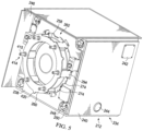
- Figs. 4 and 5 are opposite isometric views of proximal satellite 212.
- Fig. 4 depicts a distal side of the satellite and
- Fig. 5 a proximal side of the satellite, in the context of the satellite's orientation relative to the payload adaptor.
- proximal satellite 212 is roughly cuboid, and includes a housing 234 of six planar and square or rectangular wall panels. More specifically, the satellite includes a fore panel 236 and an opposing aft panel 238. Four equipment panels 240 span between the fore and aft panels.
- Proximal satellite 212 further includes a plurality of patch antennas 242, mast baffles 244, and a solar array 246 comprised of two deployable panels.
- Four thrusters 248 are mounted in brackets 250 at the four corners of aft panel 238.
- Satellite 212 may further include any appropriate operational or payload equipment, including but not limited to a fuel tank, star tracker, reaction wheel, heat sinks, radiator panels, and/or avionics. A majority of equipment may be mounted to interior surfaces of equipment panels 240.
- a proximal end portion 262 of a cylindrical core structure 260 of proximal satellite 212 which extends out through aft panel 238.
- Core structure 260 can be seen more entirely in Fig. 6 , where housing 234 is depicted as transparent.
- the core structure may also be described as a support structure, hollow column, and/or central beam.
- Core structure 260 is a hollow cylinder, spanning between aft panel 238 and fore panel 236 and enclosed in housing 234.
- the core structure may also be described as a hollow column.
- the core structure defines a central axis 270 and is centered in proximal satellite 212.
- Proximal end portion 262 is fixed to aft panel 238 and a distal end portion 264 of the core structure is fixed to fore panel 236.
- a wall 266 including a plurality of apertures 268 extends between the two end portions. Wall 266 is thin relative to the diameter of the core structure, allowing the core structure to be strong and stiff but light. Apertures 268 may further lighten the core structure, without sacrificing desired structural properties.
- Core structure 260 acts at the primary structure of the satellite, and is configured to structurally connect the satellite to both the launch vehicle and a distal satellite. More specifically, proximal end portion 262 is configured for connection to the launch vehicle payload adaptor through a mounting plate and distal end portion 264 is configured for connection to the core structure of another satellite. Each end portion of core structure 260 is configured for connection by a separation system or device. In some examples including the present example, both end portions are configured for connection by similar separation systems, as described further below. In some examples, the proximal and distal end portions may be configured for connection by different separation system or devices.
- Distal end portion 264 includes an interface flange 272 which contacts an interior surface of fore panel 236.
- the core structure is fixed to the fore panel by a plurality of fasteners extending through apertures in interface flange 272 and into the fore panel.
- Proximal end portion 262 includes a plurality of interface tabs around the circumference of wall 266, extending out from the wall and contacting an exterior surface of aft panel 238.
- the core structure is fixed to the aft panel by a plurality of fasteners extending through apertures in interface tabs 274 into the aft panel.
- proximal satellite 212 includes a fuel tank 280 mounted inside core structure 260. Such placement may help to maximize space efficiency in the satellite, allowing core structure 260 to have a large cross-section for improved strength and stiffness, without wasting interior space. Apertures 268 may facilitate necessary access and/or connections to the tank such as fluid connections to fill valves or electrical connections to sensors.
- First section 276 includes proximal portion 262, second section 278 includes distal portion 264, and the first and second sections are bolted together at an intermediate interface 284.
- Intermediate interface 284 may be described as disposed part-way along the extent of wall 266.
- Each of the first and second sections are thickened proximate intermediate interface 284, to reinforce and strengthen the connection and allow the two sections to act as a single effective structural support of satellite 212.
- wall 266 further includes apertures for a plurality of shim bolts 282 to center and precisely position tank 280 in the core structure.
- core structure 260 may include any customizations or modifications appropriate to installation, support, or integration of operational equipment of proximal satellite 212.
- Fig. 7 is an isometric view of housing 234 of proximal satellite 212, with panels 236, 238, 240 depicted as transparent.
- the panels of the housing are connected by eight corner brackets 286 and four angle clips 288.
- Corner brackets 286 include the four thruster brackets 250, and are each positioned inside a corner of housing 234, where a corner of either fore panel 236 or aft panel 238 meets corners of two equipment panels 240.
- Angle clips 288 each extend along the inside of an edge of housing 234, where edges of two equipment panels 240 meet.
- a main body 287 of each corner bracket 286 is positioned at a corresponding corner cut-out of fore panel 236 or aft panel 238. Sides of main portion 287 of the corner bracket contact interior surfaces of the three adjacent panels, and may be bonded or otherwise fixed to the panels. Corner bracket 286 further includes angle tabs 289, configured to contact an inner surface of angle clips 288. For each corner bracket 286, one angle tab 289 may be bonded or otherwise fixed to an adjacent angle clip 288. Each angle clip 288 may therefore be fixed to, and extend between, a first corner bracket at aft panel 238 and a second corner bracket at fore panel 236.
- Angle clips 288 and corner brackets 286 may structurally connect equipment panels 240 to fore panel 236 and aft panel 238, which in turn are structurally connected to the core structure of the satellite.
- Equipment panels 240 are directly connected to the core structure. In other words, the core structure is only connected to equipment panels 240 through the fore and aft panels. Loads from equipment mounted to equipment panels 240 may be transferred through fore panel 236 and aft panel 238 to the core structure.
- Housing 234 does not form part of the primary structure of proximal satellite 212. As shown in Figs. 8-10 , core structure 260 of proximal satellite 212 connects directly to mounting plate 218 and the core structure of the distal satellite. Core structure 260 is the primary structure of proximal satellite 212, and the primary load path to the launch vehicle. Housing 234 surrounds and encloses the core structure and satellite equipment. The housing is supported by core structure 260, and not directly connected to the launch vehicle. As a result, freedom of material choice and design for housing 234 is significantly increased.
- housing 234 is roughly cuboid and composed of planar panels.
- the housing may have any shape appropriate to house satellite systems and equipment and efficiently stow inside the launch vehicle.
- the housing may be a polyhedron, may include curved panels, and/or may have an irregular shape.
- housing 234 may be symmetric or approximately symmetric about central axis 270 and/or balanced for straightforward and tumble-free separation during deployment.
- panels 236, 238, 240 comprise a composite honeycomb sandwich material.
- the panels may include any light-weight material or materials that are sufficiently strong to support mounted equipment.
- the panels may be additively manufactured and/or include additively manufactured portions that may be produced by three-dimensional (3D) printing, laser sintering of a metal alloy, or other method.
- the panels need not be designed for the strength or stiffness required of a primary structure.
- Housing 234 may be highly customizable to selected payload and operational satellite equipment. View ports, supports, shielding, access holes, or other modifications may be made to the housing without affecting the primary structure of the satellite. Particularly in combination with the rapid prototyping and design implementation capabilities of additively manufactured components, such freedom may significantly simplify design and reduce testing and certification times.
- housing 234, fore panel 236 and aft panel 238 may have the most design constraints. That is, the two panels or structures of housing 234 connected to the proximal and distal ends of the core structure may need to be configured to interface with the core structure.
- the core structure interfaces with the fore and aft panels as defined by the position and direction of the satellite thrusters.
- the core structure may connect to sides of the satellite such that the satellite may be described as mounted sideways to the launch vehicle, or may be mounted to any two opposing walls or wall portions of the housing.
- aft panel 238 includes a circular aperture 290 with six circumferential cutouts or recesses 292.
- Circular aperture 290 and recesses 292 may allow core structure 260 to protrude through aft panel 238, such that proximal end portion 262 is exterior to the aft panel as shown in Fig. 5 .
- wall 266 may extend through circular aperture 290 and six bays 294 protruding out from wall 266 may extend through recesses 292.
- aft panel 238 may include an aperture shaped to correspond to core structure 260, such that proximal end portion 262 can extend through the aft panel.
- the specific shape of proximal end portion 262 and the aperture in aft panel 238 may depend on the separation system selected, as described further below.
- fore panel 236 includes six large and three small circular apertures 296, positioned to allow devices of the separation system to extend through the panel to engage distal end portion 264 of core structure 260.
- fore panel 236 may include any aperture or apertures shaped and positioned to match the selected separation system and corresponding configuration of distal end portion 264.
- Fig. 8 depicts proximal satellite 212 connected to distal satellite 214 and mounting plate 218, as part of a satellite stack 210.
- distal satellite 214 includes a roughly cuboid housing 334 and a cylindrical core structure 360 with a proximal end portion 362 and a distal end portion 364.
- Core structure 360 spans between a fore panel 336 and an aft panel 338, with proximal end portion 362 extending out through the aft panel to connect to distal end portion 264 of proximal satellite 214.
- distal satellite 214 is identical or substantially identical to proximal satellite 212 apart from the configuration of distal end portion 364 of core structure 360. Accordingly, reference numerals for components of distal satellite 214 match those of corresponding components of proximal satellite 212.
- distal satellite 214 may include a core structure 360 matching or substantially matching and configured to connect to core structure 260 of proximal satellite 212, but may otherwise differ in design from proximal satellite 212. For example, payloads, operational equipment, and/or housings of the two satellites may differ.
- Distal end portion 364 of distal satellite 214 is more simply configured than distal end portion 264 of proximal satellite 212, as shown more clearly in Fig. 9 . Unlike distal end portion 264, distal end portion 364 does not need to be configured for connection to another core structure, in some examples including the present example. Therefore distal end portion 364 includes cylindrical wall 366 up to a circular, annular interface flange 372 for connection to the fore panel of distal satellite 214. This simpler shape may be desirably lighter. In some examples, distal end portion 364 of distal satellite 214 may match distal end portion 264 of proximal satellite 212 for simplicity of manufacture and/or satellite design. In some examples, satellite stack 210 may include three or more satellites, at least one of which may include a core configured for connection to an adjacent satellite at both proximal and distal ends.
- distal satellite 214 connects to proximal satellite 212 in the same manner as the proximal satellite connects to mounting plate 218. Accordingly, proximal end portion 362 of core structure 360 of distal satellite 214 matches proximal end portion 262 of core structure 260 of proximal satellite 212.
- Mounting plate 218 also includes a distal portion 464 which matches distal portion 264 of proximal satellite 212.
- Mounting plate 218 may act as an adaptor, facilitating structural connection between core structure 260 of proximal satellite 212 and the launch vehicle payload adaptor.
- the mounting plate includes a proximal portion 462 configured for connection to a mounting point of the payload adaptor.
- proximal portion 462 includes a square, planar face with bolt holes at each corner.
- Proximal portion 462 and distal portion 464 are joined by a cylindrical center wall with supporting braces.
- mounting plate 218 may have any geometry or configuration appropriate to provide a strong connection and efficient load path between the core structures of the satellites and the launch vehicle.
- mounting plate 218, core structure 260, and core structure 360 may act as a cantilever beam extending horizontally outward from the launch vehicle payload adaptor.
- the combined core structure is sufficiently stiff to support both proximal satellite 212 and distal satellite 214, withstanding the bending moment and vibrational loading associated with launch.
- the joined core structures also provide a strong and simple load path to the launch vehicle. As described further below, the dimensions and design of the core structures provide the needed stiffness, with minimal weight.
- stiffness of the connections between core structure 260 and core structure 360, and between core structure 260 and mounting plate 218 is important to the stiffness of the connections between core structure 260 and core structure 360, and between core structure 260 and mounting plate 218. Any effective separation system or device may be used to connect the satellites. However, a system providing direct connection between the core structures, such as is depicted in the present example, may be preferable to provide a sufficiently stiff connection.
- Satellite stack 210 includes a proximal separation system 410 connecting proximal satellite 212 and mounting plate 218, and a distal separation system 412 connecting distal satellite 214 and proximal satellite 212. As shown most clearly in Figs. 4-6 , each separation system 410, 412 includes six separable connectors 414 and three push-off pins 416. Each separable connector 414 comprises a male portion 415 and a female portion 417.
- male portions 415 of separable connectors 414 of separation system 410 are housed in bays 294 of proximal end portion 262 and extend out through an interface flange 258 of the proximal end portion to engage a corresponding female portion on the mounting plate.
- Female portions 417 of separable connectors 414 of separation system 412 are mounted in recesses in wall 266 of distal end portion 264, on an opposite side of interface flange 272 from fore panel 236. Corresponding apertures in interface flange 272 allow the respective male portions on the distal satellite to reach through the flange to female portions 417.
- Push-off pins 416 of separation system 412 are mounted similarly to female portions 417 of the separation system. That is, the push-off pins are mounted on the opposite side of interface flange 272 from fore panel 236, and extend through corresponding apertures in the interface flange and fore panel to contact an interface flange of the proximal portion of distal satellite 214.
- Interface flange 258 of proximal end portion 262 of proximal satellite 212 includes three scallops 420 to engage the push-off pins on mounting plate 218.
- Separable connectors 414 and push-off pins 416 of separation systems 410, 412 are spaced evenly around the circumference of core structures 260, 360.
- Each device 414, 416 of the separation systems is spring actuated for smooth and reliable separation, and connected to a control system for coordinated triggering.
- devices 414, 416 of separation system 410 are not interposed between mounting plate 218 and core structure 260.
- the devices of separation system 412 are not interposed between core structure 260 and core structure 360.
- Interface flange 258 of proximal end portion 262 of core structure 260 contacts mounting plate 218 directly.
- Interface flange 272 of distal end portion 264 of core structure 260 and interface flange 358 of proximal end portion 362 of core structure 360 contact the inner and exterior faces of fore panel 236 of proximal satellite respectively, with only the fore panel between the two flanges.
- the direct connection between core structures may result in the desired stiffness.
- Devices of the separation systems may also be individually configured to facilitate a stiff connection.
- separation system 412 further includes two separable housing connectors 430, shown in Figs. 8 and 10 .
- Each housing connector 430 includes a first bracket 431 mounted to fore panel 236 of proximal satellite 212 and a second bracket mounted to aft panel 338 of distal satellite 214.
- the first and second brackets 431, 432 are connected by a spring-actuated releasable mechanism similar to separable connectors 414. Together the two connected brackets 431, 432 have an axial extent matching proximal end portion 362 of the distal satellite, allowing housing connectors 430 to bridge between the two satellites when core structure 260 is connected to core structure 360.
- Housing connectors 430 may be configured and/or positioned according to the geometry or other properties of housings 234 and 334. In some examples including the present example, the two housing connectors are positioned at opposing outer lateral edges of the satellites to provide additional lateral stability to the connection between the satellites, and assist in tumble-free separation.
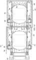
- Fig. 9 is a cross-sectional view of the primary structure of satellite stack 210, including mounting plate 218, separation system 410, core structure 260, separation system 412, and core structure 360.
- Each core structure has an inner diameter 424 as defined by an interior surface of wall 266 or 366.
- Each core structure 260, 360 also has a length 426 from the interface flange at the proximal end to the interface flange at the distal end. Inner diameter 424 and length 426 are the same for core structure 260 and core structure 360.
- the core structures have an inner diameter 424 of approximately 12 inches (approximately 30 cm) and a length of approximately 20 inches (approximately 51 cm). In some examples including the present example, the core structures have an inner diameter 424 of 12 inches (30 cm) and a length of 20 inches (51 cm).
- Walls 266, 366 of the core structures may have a thickness of between approximately 100 and 200 thousandths of an inch (between approximately 2.5 mm and 5.1 mm). Walls 266, 366 of the core structures may have a thickness of between 100 and 200 thousandths of an inch (between 2.5 mm and 5.1 mm).
- core structures 260, 360 may be any size appropriate to a satellite's size and weight. That is, the core structure design may be applicable from microsats up through full-sized satellites.
- each core structure includes two arrays of apertures 428, with a first array in the first section and a second array in the second section.
- the apertures may be arranged in additional arrays, and in examples such as a unitary core structure the apertures may form a single array.
- Each of apertures 268, 368 is diamond shaped.
- each aperture is approximately two inches (approximately 5.1 cm) in length and spaced approximately one quarter inch (approximately 0.6 cm) from adjacent apertures, or each aperture is two inches (5.1 cm) in length and spaced one quarter inch (0.6 cm) from adjacent apertures.
- Arrays of apertures 428 may also be described as a mesh and/or as a diamond lattice.
- the diamond shape may be particularly suited to additive manufacture. Any desired aperture shape may be used, and an appropriate aperture shape may depend on a selected method of manufacture. Aperture size and spacing may be selected according to desired structural properties and/or electromagnetic properties of the core structure.
- core structures 260, 360 are additively manufactured from metal. More specifically, the core structures may comprise laser sintered metal alloy, manufactured using direct metal laser sintering (DMLS) of an aluminum alloy. In general, the core structures may be manufactured according to any effective method and of any sufficiently strong and light material. Additive manufacture of the core structures may be particularly suited to production of the thin walls, apertures, and customized interface features.
- DMLS direct metal laser sintering
- satellites 212, 214 may be advantageously manufactured using additive manufacturing methods such as DMLS or electron beam melting (EBM).
- additive manufacturing methods such as DMLS or electron beam melting (EBM).
- fuel tank 280, angle clips 288, corner brackets 286, and/or panels 236, 238, 240 may be additively manufactured.
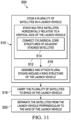
- This section describes steps of an illustrative method of deploying satellites from a launch vehicle; see Fig. 11 .
- Examples of satellites, structural satellite launch configurations, and/or launch vehicle payload adaptors and mounting plates described above may be utilized in the method steps described below. Where appropriate, reference may be made to components and systems that may be used in carrying out each step. These references are for illustration, and are not intended to limit the possible ways of carrying out any particular step of the method.
- Fig. 11 is a flowchart illustrating steps performed in an illustrative method, and may not recite the complete process or all steps of the method. Although various steps of method 500 are described below and depicted in Fig. 11 , the steps need not necessarily all be performed, and in some cases may be performed simultaneously or in a different order than the order shown.
- the method includes stowing a plurality of satellites in a launch vehicle.
- the launch vehicle may comprise any vehicle suitable to transport a payload to space.
- the launch vehicle may be an expendable autonomous vehicle, or may be a manned spacecraft.
- Step 510 may be performed as part of preparations for launch of the vehicle, and the plurality of satellites may be configured for connection to and launch in the vehicle.
- Stowing the satellites may include attaching the satellites to a payload adaptor of the launch vehicle and/or to one another using one or more separation systems and/or devices.
- the satellites may be stowed according to substeps 512-516 of step 510.
- Sub-step 512 includes stacking multiple satellites horizontally relative to a vertical axis of the launch vehicle.
- two or more satellites may be positioned adjacent one another along a horizontal axis.
- the vertical axis may correspond to an orientation of the launch vehicle during preparations for launch and/or may correspond to a launch direction or launch axis.
- the vertical axis may also be referred to as a primary axis of the launch vehicle.
- the two or more satellites may be referred to as a horizontal stack and/or lateral assembly. Only one of the satellites of the stack may be directly connected to the launch vehicle.
- Sub-step 514 of sub-step 512 includes connecting cylindrical core structures of adjacent satellites of the stacked satellites.
- a primary structure of each satellite of the plurality of satellites may include a cylindrical core structure.
- Each core structure may have the same diameter, and may be configured for connection to another core structure by a separation system.
- Within the horizontal stack of satellites each satellite may be connected to the adjacent satellites by the core structure.
- the connected core structures of the satellites of the stack may form a beam, extending horizontally out from the launch vehicle payload adaptor.
- Sub-step 516 of step 510 includes assembling and attaching plural stacks around a ring structure of the launch vehicle.
- the ring structure may be the payload adaptor of the launch vehicle, and may include a plurality of attachment or mount points.
- a plurality of horizontal stacks may be assembled according to sub-step 512, and one satellite of each stack may be connected to a mount point of the ring structure.
- the horizontal stacks of satellites and/or the horizontal axis of each stack may extend radially outward from the ring.
- Space may be understood to include any region or location desirable for deployment of one or more of the carried plurality of satellites.
- space may include, but is not limited to, a region beyond the Karman line of Earth, a region outside the atmosphere of a planetary body, or an orbit around a non-planetary body.
- Step 520 includes separating the satellites from the launch vehicle, perpendicular to the launch vehicle axis. Separating the satellites may be performed sequentially, and may be performed by actuating in turn the separation systems that connect adjacent satellites and the separation systems that connect the stacks of satellites to the ring structure of the launch vehicle.
- the separation systems may be disposed between adjacent satellites, and/or otherwise configured to provide a separating impulse in a direction parallel to the axis along which the satellites are stacked.
- each separation system may be actuated to urge a satellite away from the launch vehicle in a direction perpendicular to the primary axis of the launch vehicle, and/or in a direction radially outward from the ring structure.
- the different examples of the satellites and satellite assemblies described herein provide several advantages over known solutions for designing and mounting satellites for launch.
- illustrative examples described herein allow a sturdy and simple satellite structural design.
- illustrative examples described herein provide a stiff and lightweight primary structure.
- illustrative examples described herein allow a satellite primary structure to be rapidly and inexpensively produced by additive manufacture.
Landscapes
- Engineering & Computer Science (AREA)
- Remote Sensing (AREA)
- Aviation & Aerospace Engineering (AREA)
- Physics & Mathematics (AREA)
- Astronomy & Astrophysics (AREA)
- General Physics & Mathematics (AREA)
- Details Of Aerials (AREA)
- Laminated Bodies (AREA)
- Aiming, Guidance, Guns With A Light Source, Armor, Camouflage, And Targets (AREA)
- Radio Relay Systems (AREA)
Claims (15)
- Satellitenbaugruppe (200), umfassend: ein Trägerraumfahrzeug (124) mit einer Startachse (222); ein erstes Trennsystem (106; 410); eine erste Satellitenvorrichtung (100, 212); und eine zweite Satellitenvorrichtung (214), wobei:die erste Satellitenvorrichtung (100, 212) umfasst: ein erstes Gehäuse (234) mit einer ersten und einer zweiten Wand (236, 238), die einander gegenüberliegen; und eine erste Stützstruktur (260), die die einander gegenüberliegende erste und zweite Wand (236, 238) überspannt und von dem ersten Gehäuse (234) umschlossen ist;ein Endabschnitt (262) der ersten Stützstruktur (260) durch das erste Trennsystem (106, 410) mit der Trägerrakete (124) verbunden ist;die zweite Satellitenvorrichtung (214) umfasst: ein zweites Gehäuse (334) mit einer ersten und einer zweiten Wand (336, 338), die einander gegenüberliegen; und eine zweite Stützstruktur (360), die die einander gegenüberliegenden erste und zweite Wand des zweiten Gehäuses (334) überspannt und von dem zweiten Gehäuse (334) umschlossen ist;ein distaler Endabschnitt (264) der ersten Stützstruktur (260) in der ersten Satellitenvorrichtung (212) mit einem proximalen Endabschnitt (362) der zweiten Stützstruktur (360) in der zweiten Satellitenvorrichtung (214) verbunden ist;wobei die erste und die zweite Satellitenvorrichtung (212, 214) senkrecht zur Startachse in dem Trägerraumfahrzeug gestapelt sind.
- Satellitenbaugruppe (200) nach Anspruch 1, bei der:
die erste Stützstruktur (260) der ersten Satellitenvorrichtung (100, 212) eine Hohlsäule, optional eine zylindrische Hohlsäule, ist. - Satellitenbaugruppe (200) nach Anspruch 1 oder 2, bei der:
die erste Stützstruktur (260) aus einer lasergesinterten Metalllegierung besteht. - Satellitenbaugruppe (200) nach Anspruch 1, 2 oder 3, bei der die erste Stützstruktur (260) der ersten Satellitenvorrichtung (100, 212) einen Wandabschnitt (266) mit rautenförmigen Öffnungen (268) umfasst.
- Satellitenbaugruppe (200) nach einem der Ansprüche 1 bis 4, umfassend ein zweites Trennsystem (106, 412), wobei der Endabschnitt (262) der ersten Stützstruktur (260) der ersten Satellitenvorrichtung (100, 212) ein proximaler Endabschnitt (262) ist und wobei der distale Endabschnitt (264) der ersten Stützstruktur (260) der ersten Satellitenvorrichtung (100, 212) durch das zweite Trennsystem (106, 412) mit der zweiten Satellitenvorrichtung (214) verbunden ist.
- Satellitenbaugruppe (200) nach einem der Ansprüche 1 bis 5, bei der das erste Gehäuse (234) der ersten Satellitenvorrichtung (100, 212) ferner eine Mehrzahl von Ausrüstungspaneelen umfasst.
- Satellitenbaugruppe (200) nach Anspruch 1, bei der die erste und die zweite Satellitenvorrichtung (212, 214) konfiguriert sind, um Lasten von der zweiten Satellitenvorrichtung (214) über die Stützstruktur (260) der ersten Satellitenvorrichtung (212) auf das Trägerraumfahrzeug (124) zu übertragen.
- Satellitenbaugruppe (200) nach Anspruch 1 oder 7, bei der die erste und die zweite Stützstruktur (260, 360) der ersten und der zweiten Satellitenvorrichtung (212, 214) eine gemeinsame Mittelachse (226) haben, wenn sie verbunden sind.
- Satellitenbaugruppe (200) nach einem der Ansprüche 1 oder 7-8, bei der die erste und zweite Stützstruktur (260, 360) der ersten und zweiten Satellitenvorrichtung (212, 214) jeweils zylindrisch sind und denselben Durchmesser aufweisen.
- Satellitenbaugruppe (200) nach einem der Ansprüche 1 oder 7-9, die ferner ein zweites Trennsystem (106, 412) umfasst, wobei die erste Stützstruktur (260) und die zweite Stützstruktur (360) durch das zweite Trennsystem (106, 412) verbunden sind, und wobei die zweite gegenüberliegende Wand (238) der ersten Satellitenvorrichtung (212) mit der ersten gegenüberliegenden Wand (336) der zweiten Satellitenvorrichtung (214) durch das zweite Trennsystem (106, 412) verbunden ist.
- Satellitenbaugruppe (200) nach Anspruch 1, ferner umfassend eine Ringstruktur (217) und eine oder mehrere Satellitenvorrichtungen, die mit der ersten und zweiten Satellitenvorrichtung (212, 214) eine Mehrzahl von Satellitenvorrichtungen bilden, wobei die Mehrzahl von Satellitenvorrichtungen (212, 214) in einer Mehrzahl von Satellitenstapeln (210) befestigt sind, die gleichmäßig um den Umfang der Ringstruktur (217) verteilt sind.
- Satellitenbaugruppe (200) nach Anspruch 11, bei der die zylindrischen Strukturen einen Ausleger bilden, der sich von der Ringstruktur senkrecht zu einer Längsachse eines Trägerraumfahrzeugs erstreckt.
- Satellitenbaugruppe (200) nach einem der vorhergehenden Ansprüche, bei der die erste Stützstruktur (260) und die zweite Stützstruktur (360) zylindrisch sind und additiv gefertigt sind.
- Verfahren (500) zum Aussetzen von Satellitenvorrichtungen (212, 214) von der Satellitenbaugruppe (200) nach einem der vorhergehenden Ansprüche, mit den Schritten:Verstauen (510) der ersten und zweiten Satellitenvorrichtung (212, 214) im Inneren des Trägerraumfahrzeugs (124) durch horizontales Stapeln (512) der ersten und zweiten Satellitenvorrichtung (212, 214) relativ zur Startachse (222),Befördern (518) der ersten und zweiten Satellitenvorrichtung (212 214) in den Weltraum mit dem Trägerraumfahrzeug (124) undTrennen (520) der ersten und zweiten Satellitenvorrichtung (212, 214) von dem Trägerraumfahrzeug (124) horizontal relativ zur Startachse (222).
- Verfahren nach Anspruch 14, bei dem:das Stapeln der ersten und zweiten Satellitenvorrichtung (212, 214) das Zusammenbauen (516) mehrerer Stapel von Satellitenvorrichtungen (212, 214) umfasst, die gleichmäßig um eine Ringstruktur (217) verteilt sind; und/oderdas Trennen (520) der ersten und zweiten Satellitenvorrichtung (212, 214) das aufeinanderfolgende Trennen benachbarter Satellitenvorrichtungen (212, 214) von dem Trägerraumfahrzeug (124) umfasst.
Priority Applications (1)
| Application Number | Priority Date | Filing Date | Title |
|---|---|---|---|
| EP24195329.8A EP4461656A3 (de) | 2020-12-17 | 2021-12-15 | Gestapelte satellitenanordnungen und zugehörige verfahren |
Applications Claiming Priority (1)
| Application Number | Priority Date | Filing Date | Title |
|---|---|---|---|
| US202063126529P | 2020-12-17 | 2020-12-17 |
Related Child Applications (2)
| Application Number | Title | Priority Date | Filing Date |
|---|---|---|---|
| EP24195329.8A Division EP4461656A3 (de) | 2020-12-17 | 2021-12-15 | Gestapelte satellitenanordnungen und zugehörige verfahren |
| EP24195329.8A Division-Into EP4461656A3 (de) | 2020-12-17 | 2021-12-15 | Gestapelte satellitenanordnungen und zugehörige verfahren |
Publications (2)
| Publication Number | Publication Date |
|---|---|
| EP4015398A1 EP4015398A1 (de) | 2022-06-22 |
| EP4015398B1 true EP4015398B1 (de) | 2024-10-09 |
Family
ID=79024183
Family Applications (2)
| Application Number | Title | Priority Date | Filing Date |
|---|---|---|---|
| EP24195329.8A Pending EP4461656A3 (de) | 2020-12-17 | 2021-12-15 | Gestapelte satellitenanordnungen und zugehörige verfahren |
| EP21214774.8A Active EP4015398B1 (de) | 2020-12-17 | 2021-12-15 | Gestapelte satellitenanordnungen und zugehörige verfahren |
Family Applications Before (1)
| Application Number | Title | Priority Date | Filing Date |
|---|---|---|---|
| EP24195329.8A Pending EP4461656A3 (de) | 2020-12-17 | 2021-12-15 | Gestapelte satellitenanordnungen und zugehörige verfahren |
Country Status (7)
| Country | Link |
|---|---|
| US (2) | US12319443B2 (de) |
| EP (2) | EP4461656A3 (de) |
| JP (1) | JP2022096647A (de) |
| KR (1) | KR20220087372A (de) |
| CN (1) | CN114644140B (de) |
| AU (1) | AU2021273577A1 (de) |
| CA (1) | CA3140352A1 (de) |
Families Citing this family (14)
| Publication number | Priority date | Publication date | Assignee | Title |
|---|---|---|---|---|
| US11673695B2 (en) * | 2020-08-26 | 2023-06-13 | Lockheed Martin Corporation | Deployable fairing for rideshare satellites |
| US12537593B2 (en) * | 2022-04-03 | 2026-01-27 | Henry D Voss | ThinSat constellations that are a group of satellites for carrying payloads for experimentation and data collection which are launched into and orbit through low earth orbit (LEO) and very low earth orbit (VLEO) conditions |
| KR102513363B1 (ko) * | 2022-08-04 | 2023-03-23 | 한화시스템 주식회사 | 위성 지지장치 및 이를 구비하는 발사체 |
| CN115009549B (zh) * | 2022-08-09 | 2022-11-18 | 北京星河动力装备科技有限公司 | 锁紧释放机构及其控制方法、运载火箭 |
| US11888222B1 (en) | 2022-09-23 | 2024-01-30 | The Boeing Company | Flange for 3D printed antennas and related methods |
| KR102558240B1 (ko) | 2022-11-29 | 2023-07-21 | 한화시스템 주식회사 | 초소형 위성 보호장치 |
| KR102558237B1 (ko) * | 2022-11-29 | 2023-07-21 | 한화시스템 주식회사 | 초소형 위성 사출장치 |
| KR102558241B1 (ko) * | 2022-11-29 | 2023-07-21 | 한화시스템 주식회사 | 위성 및 위성의 제조 방법 |
| KR102566870B1 (ko) * | 2022-11-30 | 2023-08-14 | 한화시스템 주식회사 | 인공위성 탑재장치 및 인공위성 운용방법 |
| KR102529856B1 (ko) * | 2022-11-30 | 2023-05-08 | 한화시스템 주식회사 | 인공위성 탑재 장치 및 인공위성 운용 방법 |
| KR102566871B1 (ko) * | 2022-11-30 | 2023-08-14 | 한화시스템 주식회사 | 인공위성 탑재 장치 및 인공위성 운용 방법 |
| CN118992123B (zh) * | 2024-07-19 | 2025-03-11 | 北京钧天航宇技术有限公司 | 一种具备标准化卫星平台的平板式sar卫星 |
| WO2026038134A1 (en) * | 2024-08-12 | 2026-02-19 | Swissto12 Sa | Satellite with mechanical structure |
| CN120096829B (zh) * | 2025-04-27 | 2025-12-16 | 深圳市魔方卫星科技有限公司 | 一种微小卫星的释放设备 |
Citations (1)
| Publication number | Priority date | Publication date | Assignee | Title |
|---|---|---|---|---|
| WO2021081389A1 (en) * | 2019-10-25 | 2021-04-29 | Momentus Inc. | Launch and flight configurations for transfer space vehicles |
Family Cites Families (89)
| Publication number | Priority date | Publication date | Assignee | Title |
|---|---|---|---|---|
| US3976269A (en) | 1974-12-19 | 1976-08-24 | The Boeing Company | Intrinsically tuned structural panel |
| US4854526A (en) * | 1987-08-10 | 1989-08-08 | Hughes Aircraft Company | Spacecraft design enabling the compact nesting of multiple spacecraft in the launch vehicle |
| US5342465A (en) | 1988-12-09 | 1994-08-30 | Trw Inc. | Viscoelastic damping structures and related manufacturing method |
| US5280706A (en) * | 1992-06-25 | 1994-01-25 | Thiokol Corporation | Composite/metal hybrid rocket motor case and methods for manufacturing |
| US5755406A (en) | 1995-12-22 | 1998-05-26 | Hughes Electronics | Modular, independent subsystem design satellite bus and variable communication payload configurations and missions |
| US6207256B1 (en) | 1997-10-02 | 2001-03-27 | S. Iwasa | Space truss composite panel |
| US6199801B1 (en) | 1997-12-01 | 2001-03-13 | Csa Engineering, Inc. | Whole-spacecraft passive isolation devices |
| US6064352A (en) | 1998-04-01 | 2000-05-16 | Trw Inc. | Composite isogrid structures for parabolic surfaces |
| US6206327B1 (en) * | 1999-03-31 | 2001-03-27 | Lockheed Martin Corporation | Modular spacecraft bus |
| US6227493B1 (en) | 1999-04-06 | 2001-05-08 | Planetary Systems Corporation | Reusable, separable, structural connector assembly |
| US6290183B1 (en) | 1999-10-19 | 2001-09-18 | Csa Engineering, Inc. | Three-axis, six degree-of-freedom, whole-spacecraft passive vibration isolation system |
| US7716897B2 (en) | 2001-07-03 | 2010-05-18 | Merrifield Donald V | Deployable rectangular truss beam with orthogonally-hinged folding diagonals |
| JP3918699B2 (ja) | 2002-09-20 | 2007-05-23 | ヤマハ株式会社 | 中空パネル |
| US20060185277A1 (en) | 2004-08-16 | 2006-08-24 | Utah State University | Modular platform system |
| US7249756B1 (en) | 2006-02-01 | 2007-07-31 | Csa Engineering, Inc. | Low-profile, multi-axis, highly passively damped, vibration isolation mount |
| US20110296675A1 (en) | 2009-08-26 | 2011-12-08 | Roopnarine | Means for rapidly assembling a spacecraft |
| US8458976B2 (en) | 2009-10-16 | 2013-06-11 | The Boeing Company | Thermal protection blanket assembly |
| US8739515B2 (en) | 2009-11-24 | 2014-06-03 | United Technologies Corporation | Variable area fan nozzle cowl airfoil |
| US20140065433A1 (en) | 2010-01-06 | 2014-03-06 | General Electric Company | Coatings for dissipating vibration-induced stresses in components and components provided therewith |
| FR2959490B1 (fr) * | 2010-04-28 | 2012-07-13 | Astrium Sas | Satellite a structure simplifiee, allegee et economique, et son procede de mise en oeuvre |
| JP5569150B2 (ja) * | 2010-05-31 | 2014-08-13 | 株式会社Ihi | 人工衛星搭載システム |
| US8550408B2 (en) * | 2010-07-16 | 2013-10-08 | The Boeing Company | Dual evolved expendable launch vehicle (EELV) secondary payload adaptor (ESPA) port small satellite design |
| US9086033B2 (en) * | 2010-09-13 | 2015-07-21 | Experimental Propulsion Lab, Llc | Additive manufactured propulsion system |
| US9045242B2 (en) | 2010-09-22 | 2015-06-02 | The Boeing Company | Mechanically fastened large pressurized vehicle structure |
| US8393582B1 (en) * | 2010-10-12 | 2013-03-12 | United Launch Alliance, L.L.C. | Apparatus and method of transferring and utilizing residual fuel of a launch vehicle upper stage |
| US8708322B2 (en) | 2010-11-05 | 2014-04-29 | Honeywell International Inc. | Payload launch lock mechanism |
| US8608114B2 (en) | 2011-04-15 | 2013-12-17 | Hkm Enterprises Inc. | Platform and launch initiation system for secondary spacecraft for launch vehicle |
| US9845600B2 (en) | 2011-07-01 | 2017-12-19 | Embry-Riddle Aeronautical University, Inc. | Highly vented truss wall honeycomb structures |
| US8939409B2 (en) | 2012-05-07 | 2015-01-27 | The Johns Hopkins University | Adaptor system for deploying small satellites |
| US8973873B2 (en) | 2012-10-15 | 2015-03-10 | The Boeing Company | Spacecraft propellant tank mount |
| US8807485B2 (en) | 2012-06-07 | 2014-08-19 | The Boeing Company | Systems for interconnecting dual manifested spacecraft |
| CA2913356C (en) | 2012-06-21 | 2020-07-21 | Pantero Technologies Inc. | Planar space frame for vehicle structure and housing of components |
| US9475594B2 (en) | 2012-09-25 | 2016-10-25 | Honeywell International Inc. | Launch lock assemblies with reduced preload and spacecraft isolation systems including the same |
| US9718565B1 (en) * | 2012-10-04 | 2017-08-01 | TriSept Corporation | Configurable-mass, distributed architecture rideshare dispenser for launch vehicle and method of operation thereof |
| US9296493B2 (en) * | 2013-02-28 | 2016-03-29 | The Boeing Company | Spacecraft with open sides |
| US9027889B2 (en) * | 2013-02-28 | 2015-05-12 | The Boeing Comapny | Modular core structure for dual-manifest spacecraft launch |
| US9796486B1 (en) * | 2013-03-15 | 2017-10-24 | Planetary Resources Development Corp. | Integrated propulsion and primary structure module for microsatellites |
| US20150048209A1 (en) | 2013-08-16 | 2015-02-19 | Robert Hoyt | Structures with Internal Microstructures to Provide Multifunctional Capabilities |
| US9981446B2 (en) | 2013-09-03 | 2018-05-29 | The Boeing Company | Structural inserts for honeycomb structures |
| WO2015130377A2 (en) | 2013-12-12 | 2015-09-03 | United Technologies Corporation | Structural honeycomb panel |
| EP3092349A4 (de) | 2014-01-07 | 2017-09-06 | Nama Development LLC | 3d-wabenschaumstruktur |
| US9567115B2 (en) | 2014-07-29 | 2017-02-14 | Victor Dube | Door mechanism for satellite deployer system |
| FR3029833B1 (fr) | 2014-12-15 | 2016-12-30 | Alain Toufine | Procede d'obtention de structures sandwich fortement anisotropes integrant des fonctions mecaniques, thermiques et ame et peaux de structures obtenues par gradient metallurgique ou composite |
| US10895015B1 (en) | 2014-12-16 | 2021-01-19 | Hrl Laboratories, Llc | Thin-walled high temperature alloy structures via multi-material additive manufacturing |
| FR3031969B1 (fr) * | 2015-01-27 | 2017-01-27 | Airbus Defence & Space Sas | Satellite artificiel et procede de remplissage d'un reservoir de gaz propulsif dudit satellite artificiel |
| US20160282067A1 (en) | 2015-03-23 | 2016-09-29 | The Boeing Company | High thermal conductivity composite base plate |
| US10392135B2 (en) | 2015-03-30 | 2019-08-27 | Worldvu Satellites Limited | Satellite radiator panels with combined stiffener/heat pipe |
| FR3035076B1 (fr) * | 2015-04-17 | 2018-04-20 | Thales | Procede d'amenagement d'une pluralite de vaisseaux spatiaux sous la coiffe d'un lanceur, assemblage resultant d'un tel procede et dispenser adapte a un tel assemblage |
| US9718566B2 (en) | 2015-04-30 | 2017-08-01 | Worldvu Satellites Limited | Stackable satellites and method of stacking same |
| EP3095714A1 (de) | 2015-05-19 | 2016-11-23 | Airbus DS GmbH | Modularer satellit |
| US10556710B2 (en) | 2015-06-16 | 2020-02-11 | Airbus Defence And Space, S.A. | Lightweight passive attenuator for spacecraft |
| US10486837B2 (en) * | 2015-06-22 | 2019-11-26 | Worldvu Satellites Limited | Payload dispensing system |
| CN107921564B (zh) | 2015-08-03 | 2021-01-29 | 空间制造公司 | 航天器装置在太空中的制造和装配 |
| US20180223947A1 (en) | 2015-08-07 | 2018-08-09 | Moog Inc. | Payload shock and vibration isolator |
| US9796488B2 (en) * | 2015-10-02 | 2017-10-24 | The Boeing Company | Dual port payload attach ring compatible satellite |
| US9828117B2 (en) | 2016-02-04 | 2017-11-28 | United Launch Alliance, L.L.C. | Tensioning apparatus and system for clamping joints |
| JP6644132B2 (ja) | 2016-03-31 | 2020-02-12 | 三菱電機株式会社 | ヒートパイプパネルを用いた放熱装置 |
| US11525642B2 (en) | 2016-10-17 | 2022-12-13 | Roccor, Llc | Thermal energy storage devices, systems, and methods |
| US10370124B2 (en) | 2016-10-22 | 2019-08-06 | Quad-M, Inc. | Satellite deployer spring method, system, and apparatus utilizing a bore conforming hinged leaf spring construction |
| US10407189B1 (en) | 2016-10-27 | 2019-09-10 | Space Systems/Loral, Llc | Spacecraft exoskeleton truss structure |
| US10538347B1 (en) * | 2016-11-14 | 2020-01-21 | Space Systems/Loral, Llc | Smallsat payload configuration |
| US10589878B2 (en) | 2016-12-12 | 2020-03-17 | The Boeing Company | Additively manufactured reinforced structure |
| CN106694884B (zh) | 2016-12-29 | 2020-02-21 | 西安铂力特增材技术股份有限公司 | 一种具有梯度功能性的镂空点阵夹层及其制造方法 |
| EP3345754B1 (de) | 2017-01-10 | 2019-09-25 | Airbus Operations GmbH | Sandwichplatte mit vertieftem kanalnetzwerk |
| US10392097B2 (en) | 2017-02-16 | 2019-08-27 | The Boeing Company | Efficient sub-structures |
| US11072441B2 (en) * | 2017-03-03 | 2021-07-27 | Northrop Grumman Systems Corporation | Stackable spacecraft |
| US10604280B2 (en) | 2017-03-03 | 2020-03-31 | U.S.A. As Represented By The Administrator Of The National Aeronautics And Space Administration | Capsulation satellite system |
| US10647081B2 (en) | 2017-03-31 | 2020-05-12 | The Boeing Company | Lightweight honeycomb thermal insulation structure |
| US10633123B2 (en) * | 2017-04-05 | 2020-04-28 | Space Systems/Loral, Llc | Exoskeletal launch support structure |
| EP3634858B1 (de) | 2017-05-10 | 2022-01-12 | RUAG Space AB | Nutzdatenausgabe |
| EP3431398B1 (de) | 2017-07-21 | 2019-09-11 | Technische Universität München | Satellitenabdeckplatte |
| US10751970B2 (en) | 2017-12-28 | 2020-08-25 | Industrial Technology Research Institute | Three-dimensional structure |
| CN208392799U (zh) | 2018-02-28 | 2019-01-18 | 天津大学 | 一种聚氨酯泡沫自适应减振降噪泡沫夹层板 |
| US12398704B2 (en) | 2018-04-17 | 2025-08-26 | Raytheon Company | Thermally-enhanced and deployable structures |
| US11135763B2 (en) | 2018-05-02 | 2021-10-05 | Northrop Grumman Systems Corporation | Assemblies formed by additive manufacturing, radar absorbing structures, and related methods |
| EP3569396B1 (de) | 2018-05-14 | 2022-11-16 | Airbus Operations GmbH | Verfahren zur formung einer strukturellen komponente für ein flugwerk eines flugzeugs oder raumfahrzeugs und strukturelle komponente für ein flugwerk eines flugzeugs oder raumfahrzeugs |
| JP7145975B2 (ja) | 2018-05-24 | 2022-10-03 | ザ ヨーロピアン ユニオン、リプレゼンテッド バイ ザ ヨーロピアン コミッション | 単一又はスタックした複数の打ち上げのための効率的な衛星構造の概念 |
| US10538341B1 (en) | 2018-07-06 | 2020-01-21 | Vector Launch Inc. | Self-mating modular satellite bus |
| US10536107B1 (en) | 2018-10-10 | 2020-01-14 | Vector Launch Inc. | Satellite modular power supply |
| CN109317677A (zh) | 2018-10-16 | 2019-02-12 | 北京星航机电装备有限公司 | 一种通过增材制造方法制备的蜂窝夹层结构 |
| CA3023416C (en) | 2018-11-06 | 2019-04-30 | Caspar Lilholt | Assemblable and disassemblable enclosure |
| US11794927B2 (en) | 2019-08-28 | 2023-10-24 | The Boeing Company | Additively manufactured spacecraft panel |
| US11858667B1 (en) * | 2019-10-16 | 2024-01-02 | Amazon Technologies, Inc. | Satellite dispenser |
| CN111532452B (zh) * | 2020-05-18 | 2022-04-22 | 天津爱思达航天科技有限公司 | 一种多星分配器承力结构 |
| US11827389B2 (en) | 2020-05-18 | 2023-11-28 | The Boeing Company | Additively manufactured satellite |
| US11542041B2 (en) | 2020-05-18 | 2023-01-03 | The Boeing Company | Additively manufactured satellite panel with damping |
| US11802606B2 (en) | 2020-05-18 | 2023-10-31 | The Boeing Company | Planate dynamic isolator |
| CN111762338A (zh) * | 2020-05-25 | 2020-10-13 | 航天科工空间工程发展有限公司 | 折叠式平板卫星构型 |
| US11492147B2 (en) * | 2020-07-30 | 2022-11-08 | The Aerospace Corporation | Stackable satellite structure and deployment method |
-
2021
- 2021-11-24 CA CA3140352A patent/CA3140352A1/en active Pending
- 2021-11-24 AU AU2021273577A patent/AU2021273577A1/en active Pending
- 2021-12-03 KR KR1020210171607A patent/KR20220087372A/ko active Pending
- 2021-12-15 CN CN202111537981.XA patent/CN114644140B/zh active Active
- 2021-12-15 EP EP24195329.8A patent/EP4461656A3/de active Pending
- 2021-12-15 EP EP21214774.8A patent/EP4015398B1/de active Active
- 2021-12-16 JP JP2021204342A patent/JP2022096647A/ja active Pending
- 2021-12-16 US US17/553,593 patent/US12319443B2/en active Active
-
2025
- 2025-05-13 US US19/206,704 patent/US20250269982A1/en active Pending
Patent Citations (1)
| Publication number | Priority date | Publication date | Assignee | Title |
|---|---|---|---|---|
| WO2021081389A1 (en) * | 2019-10-25 | 2021-04-29 | Momentus Inc. | Launch and flight configurations for transfer space vehicles |
Also Published As
| Publication number | Publication date |
|---|---|
| JP2022096647A (ja) | 2022-06-29 |
| CN114644140B (zh) | 2026-02-17 |
| KR20220087372A (ko) | 2022-06-24 |
| CN114644140A (zh) | 2022-06-21 |
| EP4461656A3 (de) | 2025-01-15 |
| CA3140352A1 (en) | 2022-06-17 |
| US20220194632A1 (en) | 2022-06-23 |
| US20250269982A1 (en) | 2025-08-28 |
| US12319443B2 (en) | 2025-06-03 |
| AU2021273577A1 (en) | 2022-07-07 |
| EP4015398A1 (de) | 2022-06-22 |
| EP4461656A2 (de) | 2024-11-13 |
Similar Documents
| Publication | Publication Date | Title |
|---|---|---|
| EP4015398B1 (de) | Gestapelte satellitenanordnungen und zugehörige verfahren | |
| US11708181B2 (en) | Methods and apparatus for performing propulsion operations using electric propulsion systems | |
| EP3289313B1 (de) | System und verfahren zum montieren und einsetzen von satelliten | |
| EP3782914B1 (de) | Satellitenausgeber und verfahren zur unterstützung einer vielzahl von satelliten | |
| EP3254973B1 (de) | Stapelbarer pfannkuchen satellit | |
| CN103387058B (zh) | 多航天器发射系统 | |
| US5314146A (en) | Multi-mission spacecraft bus having space frame structural design | |
| US6206327B1 (en) | Modular spacecraft bus | |
| EP3268282B1 (de) | Umlaufbahnmontage von kommunikationssatelliten | |
| CN108482711B (zh) | 使用电气推进系统执行推进操作的方法和装置 | |
| EP3305666B1 (de) | Raumfahrzeug, verfahren und system | |
| CN113682494A (zh) | 增材制造的卫星 | |
| JPH10203494A (ja) | モジュール式宇宙船構造体 | |
| US20160288931A1 (en) | Satellite frame and method of making a satellite | |
| JPH06191500A (ja) | 宇宙船 | |
| JP3431226B2 (ja) | トランジション | |
| CN115371500A (zh) | 一种星箭载一体化飞行器 | |
| CN118372986A (zh) | 一种母星及子母卫星组合体 | |
| WO2024220199A1 (en) | Solar array spring elements for stacking spacecraft | |
| EP4686657A1 (de) | Plattformstruktur für raumfahrzeug | |
| Rossoni et al. | Developments in nano-satellite structural subsystem design at NASA-GSFC | |
| US20250382071A1 (en) | Space module designed to be deployed in space to form a space platform and associated space platform | |
| WO2025198643A2 (en) | Reusable and reconfigurable launch vehicle |
Legal Events
| Date | Code | Title | Description |
|---|---|---|---|
| PUAI | Public reference made under article 153(3) epc to a published international application that has entered the european phase |
Free format text: ORIGINAL CODE: 0009012 |
|
| STAA | Information on the status of an ep patent application or granted ep patent |
Free format text: STATUS: THE APPLICATION HAS BEEN PUBLISHED |
|
| AK | Designated contracting states |
Kind code of ref document: A1 Designated state(s): AL AT BE BG CH CY CZ DE DK EE ES FI FR GB GR HR HU IE IS IT LI LT LU LV MC MK MT NL NO PL PT RO RS SE SI SK SM TR |
|
| STAA | Information on the status of an ep patent application or granted ep patent |
Free format text: STATUS: REQUEST FOR EXAMINATION WAS MADE |
|
| 17P | Request for examination filed |
Effective date: 20221222 |
|
| RBV | Designated contracting states (corrected) |
Designated state(s): AL AT BE BG CH CY CZ DE DK EE ES FI FR GB GR HR HU IE IS IT LI LT LU LV MC MK MT NL NO PL PT RO RS SE SI SK SM TR |
|
| RAP3 | Party data changed (applicant data changed or rights of an application transferred) |
Owner name: THE BOEING COMPANY |
|
| GRAP | Despatch of communication of intention to grant a patent |
Free format text: ORIGINAL CODE: EPIDOSNIGR1 |
|
| STAA | Information on the status of an ep patent application or granted ep patent |
Free format text: STATUS: GRANT OF PATENT IS INTENDED |
|
| RIC1 | Information provided on ipc code assigned before grant |
Ipc: B64G 1/00 20060101ALN20231019BHEP Ipc: B64G 1/64 20060101AFI20231019BHEP |
|
| RIC1 | Information provided on ipc code assigned before grant |
Ipc: B64G 1/00 20060101ALN20231023BHEP Ipc: B64G 1/64 20060101AFI20231023BHEP |
|
| INTG | Intention to grant announced |
Effective date: 20231108 |
|
| P01 | Opt-out of the competence of the unified patent court (upc) registered |
Effective date: 20231201 |
|
| GRAJ | Information related to disapproval of communication of intention to grant by the applicant or resumption of examination proceedings by the epo deleted |
Free format text: ORIGINAL CODE: EPIDOSDIGR1 |
|
| STAA | Information on the status of an ep patent application or granted ep patent |
Free format text: STATUS: REQUEST FOR EXAMINATION WAS MADE |
|
| GRAP | Despatch of communication of intention to grant a patent |
Free format text: ORIGINAL CODE: EPIDOSNIGR1 |
|
| STAA | Information on the status of an ep patent application or granted ep patent |
Free format text: STATUS: GRANT OF PATENT IS INTENDED |
|
| INTC | Intention to grant announced (deleted) | ||
| RIC1 | Information provided on ipc code assigned before grant |
Ipc: B64G 1/00 20060101ALN20240320BHEP Ipc: B64G 1/64 20060101AFI20240320BHEP |
|
| INTG | Intention to grant announced |
Effective date: 20240405 |
|
| GRAS | Grant fee paid |
Free format text: ORIGINAL CODE: EPIDOSNIGR3 |
|
| GRAA | (expected) grant |
Free format text: ORIGINAL CODE: 0009210 |
|
| STAA | Information on the status of an ep patent application or granted ep patent |
Free format text: STATUS: THE PATENT HAS BEEN GRANTED |
|
| AK | Designated contracting states |
Kind code of ref document: B1 Designated state(s): AL AT BE BG CH CY CZ DE DK EE ES FI FR GB GR HR HU IE IS IT LI LT LU LV MC MK MT NL NO PL PT RO RS SE SI SK SM TR |
|
| REG | Reference to a national code |
Ref country code: CH Ref legal event code: EP |
|
| REG | Reference to a national code |
Ref country code: DE Ref legal event code: R096 Ref document number: 602021019887 Country of ref document: DE |
|
| REG | Reference to a national code |
Ref country code: IE Ref legal event code: FG4D |
|
| REG | Reference to a national code |
Ref country code: LT Ref legal event code: MG9D |
|
| REG | Reference to a national code |
Ref country code: NL Ref legal event code: MP Effective date: 20241009 |
|
| REG | Reference to a national code |
Ref country code: AT Ref legal event code: MK05 Ref document number: 1730363 Country of ref document: AT Kind code of ref document: T Effective date: 20241009 |
|
| PG25 | Lapsed in a contracting state [announced via postgrant information from national office to epo] |
Ref country code: NL Free format text: LAPSE BECAUSE OF FAILURE TO SUBMIT A TRANSLATION OF THE DESCRIPTION OR TO PAY THE FEE WITHIN THE PRESCRIBED TIME-LIMIT Effective date: 20241009 |
|
| PG25 | Lapsed in a contracting state [announced via postgrant information from national office to epo] |
Ref country code: NL Free format text: LAPSE BECAUSE OF FAILURE TO SUBMIT A TRANSLATION OF THE DESCRIPTION OR TO PAY THE FEE WITHIN THE PRESCRIBED TIME-LIMIT Effective date: 20241009 |
|
| PG25 | Lapsed in a contracting state [announced via postgrant information from national office to epo] |
Ref country code: HR Free format text: LAPSE BECAUSE OF FAILURE TO SUBMIT A TRANSLATION OF THE DESCRIPTION OR TO PAY THE FEE WITHIN THE PRESCRIBED TIME-LIMIT Effective date: 20241009 Ref country code: PT Free format text: LAPSE BECAUSE OF FAILURE TO SUBMIT A TRANSLATION OF THE DESCRIPTION OR TO PAY THE FEE WITHIN THE PRESCRIBED TIME-LIMIT Effective date: 20250210 Ref country code: IS Free format text: LAPSE BECAUSE OF FAILURE TO SUBMIT A TRANSLATION OF THE DESCRIPTION OR TO PAY THE FEE WITHIN THE PRESCRIBED TIME-LIMIT Effective date: 20250209 |
|
| PG25 | Lapsed in a contracting state [announced via postgrant information from national office to epo] |
Ref country code: FI Free format text: LAPSE BECAUSE OF FAILURE TO SUBMIT A TRANSLATION OF THE DESCRIPTION OR TO PAY THE FEE WITHIN THE PRESCRIBED TIME-LIMIT Effective date: 20241009 |
|
| PG25 | Lapsed in a contracting state [announced via postgrant information from national office to epo] |
Ref country code: BG Free format text: LAPSE BECAUSE OF FAILURE TO SUBMIT A TRANSLATION OF THE DESCRIPTION OR TO PAY THE FEE WITHIN THE PRESCRIBED TIME-LIMIT Effective date: 20241009 |
|
| PG25 | Lapsed in a contracting state [announced via postgrant information from national office to epo] |
Ref country code: ES Free format text: LAPSE BECAUSE OF FAILURE TO SUBMIT A TRANSLATION OF THE DESCRIPTION OR TO PAY THE FEE WITHIN THE PRESCRIBED TIME-LIMIT Effective date: 20241009 |
|
| PG25 | Lapsed in a contracting state [announced via postgrant information from national office to epo] |
Ref country code: NO Free format text: LAPSE BECAUSE OF FAILURE TO SUBMIT A TRANSLATION OF THE DESCRIPTION OR TO PAY THE FEE WITHIN THE PRESCRIBED TIME-LIMIT Effective date: 20250109 |
|
| PG25 | Lapsed in a contracting state [announced via postgrant information from national office to epo] |
Ref country code: LV Free format text: LAPSE BECAUSE OF FAILURE TO SUBMIT A TRANSLATION OF THE DESCRIPTION OR TO PAY THE FEE WITHIN THE PRESCRIBED TIME-LIMIT Effective date: 20241009 Ref country code: GR Free format text: LAPSE BECAUSE OF FAILURE TO SUBMIT A TRANSLATION OF THE DESCRIPTION OR TO PAY THE FEE WITHIN THE PRESCRIBED TIME-LIMIT Effective date: 20250110 Ref country code: AT Free format text: LAPSE BECAUSE OF FAILURE TO SUBMIT A TRANSLATION OF THE DESCRIPTION OR TO PAY THE FEE WITHIN THE PRESCRIBED TIME-LIMIT Effective date: 20241009 |
|
| PG25 | Lapsed in a contracting state [announced via postgrant information from national office to epo] |
Ref country code: PL Free format text: LAPSE BECAUSE OF FAILURE TO SUBMIT A TRANSLATION OF THE DESCRIPTION OR TO PAY THE FEE WITHIN THE PRESCRIBED TIME-LIMIT Effective date: 20241009 |
|
| PG25 | Lapsed in a contracting state [announced via postgrant information from national office to epo] |
Ref country code: RS Free format text: LAPSE BECAUSE OF FAILURE TO SUBMIT A TRANSLATION OF THE DESCRIPTION OR TO PAY THE FEE WITHIN THE PRESCRIBED TIME-LIMIT Effective date: 20250109 |
|
| PG25 | Lapsed in a contracting state [announced via postgrant information from national office to epo] |
Ref country code: SM Free format text: LAPSE BECAUSE OF FAILURE TO SUBMIT A TRANSLATION OF THE DESCRIPTION OR TO PAY THE FEE WITHIN THE PRESCRIBED TIME-LIMIT Effective date: 20241009 |
|
| PG25 | Lapsed in a contracting state [announced via postgrant information from national office to epo] |
Ref country code: MC Free format text: LAPSE BECAUSE OF FAILURE TO SUBMIT A TRANSLATION OF THE DESCRIPTION OR TO PAY THE FEE WITHIN THE PRESCRIBED TIME-LIMIT Effective date: 20241009 |
|
| PG25 | Lapsed in a contracting state [announced via postgrant information from national office to epo] |
Ref country code: DK Free format text: LAPSE BECAUSE OF FAILURE TO SUBMIT A TRANSLATION OF THE DESCRIPTION OR TO PAY THE FEE WITHIN THE PRESCRIBED TIME-LIMIT Effective date: 20241009 |
|
| REG | Reference to a national code |
Ref country code: DE Ref legal event code: R097 Ref document number: 602021019887 Country of ref document: DE |
|
| PG25 | Lapsed in a contracting state [announced via postgrant information from national office to epo] |
Ref country code: EE Free format text: LAPSE BECAUSE OF FAILURE TO SUBMIT A TRANSLATION OF THE DESCRIPTION OR TO PAY THE FEE WITHIN THE PRESCRIBED TIME-LIMIT Effective date: 20241009 |
|
| PG25 | Lapsed in a contracting state [announced via postgrant information from national office to epo] |
Ref country code: RO Free format text: LAPSE BECAUSE OF FAILURE TO SUBMIT A TRANSLATION OF THE DESCRIPTION OR TO PAY THE FEE WITHIN THE PRESCRIBED TIME-LIMIT Effective date: 20241009 |
|
| PG25 | Lapsed in a contracting state [announced via postgrant information from national office to epo] |
Ref country code: SK Free format text: LAPSE BECAUSE OF FAILURE TO SUBMIT A TRANSLATION OF THE DESCRIPTION OR TO PAY THE FEE WITHIN THE PRESCRIBED TIME-LIMIT Effective date: 20241009 |
|
| PG25 | Lapsed in a contracting state [announced via postgrant information from national office to epo] |
Ref country code: CZ Free format text: LAPSE BECAUSE OF FAILURE TO SUBMIT A TRANSLATION OF THE DESCRIPTION OR TO PAY THE FEE WITHIN THE PRESCRIBED TIME-LIMIT Effective date: 20241009 |
|
| PG25 | Lapsed in a contracting state [announced via postgrant information from national office to epo] |
Ref country code: IT Free format text: LAPSE BECAUSE OF FAILURE TO SUBMIT A TRANSLATION OF THE DESCRIPTION OR TO PAY THE FEE WITHIN THE PRESCRIBED TIME-LIMIT Effective date: 20241009 |
|
| REG | Reference to a national code |
Ref country code: CH Ref legal event code: PL |
|
| PLBE | No opposition filed within time limit |
Free format text: ORIGINAL CODE: 0009261 |
|
| STAA | Information on the status of an ep patent application or granted ep patent |
Free format text: STATUS: NO OPPOSITION FILED WITHIN TIME LIMIT |
|
| PG25 | Lapsed in a contracting state [announced via postgrant information from national office to epo] |
Ref country code: LU Free format text: LAPSE BECAUSE OF NON-PAYMENT OF DUE FEES Effective date: 20241215 |
|
| PG25 | Lapsed in a contracting state [announced via postgrant information from national office to epo] |
Ref country code: SE Free format text: LAPSE BECAUSE OF FAILURE TO SUBMIT A TRANSLATION OF THE DESCRIPTION OR TO PAY THE FEE WITHIN THE PRESCRIBED TIME-LIMIT Effective date: 20241009 |
|
| 26N | No opposition filed |
Effective date: 20250710 |
|
| REG | Reference to a national code |
Ref country code: BE Ref legal event code: MM Effective date: 20241231 |
|
| PG25 | Lapsed in a contracting state [announced via postgrant information from national office to epo] |
Ref country code: BE Free format text: LAPSE BECAUSE OF NON-PAYMENT OF DUE FEES Effective date: 20241231 |
|
| PG25 | Lapsed in a contracting state [announced via postgrant information from national office to epo] |
Ref country code: CH Free format text: LAPSE BECAUSE OF NON-PAYMENT OF DUE FEES Effective date: 20241231 |
|
| PG25 | Lapsed in a contracting state [announced via postgrant information from national office to epo] |
Ref country code: IE Free format text: LAPSE BECAUSE OF NON-PAYMENT OF DUE FEES Effective date: 20241215 |
|
| PGFP | Annual fee paid to national office [announced via postgrant information from national office to epo] |
Ref country code: GB Payment date: 20251229 Year of fee payment: 5 |
|
| PGFP | Annual fee paid to national office [announced via postgrant information from national office to epo] |
Ref country code: FR Payment date: 20251226 Year of fee payment: 5 |
|
| PGFP | Annual fee paid to national office [announced via postgrant information from national office to epo] |
Ref country code: DE Payment date: 20251229 Year of fee payment: 5 |