EP3305666B1 - Raumfahrzeug, verfahren und system - Google Patents
Raumfahrzeug, verfahren und system Download PDFInfo
- Publication number
- EP3305666B1 EP3305666B1 EP17192203.2A EP17192203A EP3305666B1 EP 3305666 B1 EP3305666 B1 EP 3305666B1 EP 17192203 A EP17192203 A EP 17192203A EP 3305666 B1 EP3305666 B1 EP 3305666B1
- Authority
- EP
- European Patent Office
- Prior art keywords
- deployable
- configuration
- module
- spacecraft
- launch
- Prior art date
- Legal status (The legal status is an assumption and is not a legal conclusion. Google has not performed a legal analysis and makes no representation as to the accuracy of the status listed.)
- Active
Links
Images


Classifications
-
- B—PERFORMING OPERATIONS; TRANSPORTING
- B64—AIRCRAFT; AVIATION; COSMONAUTICS
- B64G—COSMONAUTICS; VEHICLES OR EQUIPMENT THEREFOR
- B64G1/00—Cosmonautic vehicles
- B64G1/10—Artificial satellites; Systems of such satellites; Interplanetary vehicles
-
- B—PERFORMING OPERATIONS; TRANSPORTING
- B64—AIRCRAFT; AVIATION; COSMONAUTICS
- B64G—COSMONAUTICS; VEHICLES OR EQUIPMENT THEREFOR
- B64G1/00—Cosmonautic vehicles
- B64G1/002—Launch systems
-
- B—PERFORMING OPERATIONS; TRANSPORTING
- B64—AIRCRAFT; AVIATION; COSMONAUTICS
- B64G—COSMONAUTICS; VEHICLES OR EQUIPMENT THEREFOR
- B64G1/00—Cosmonautic vehicles
- B64G1/22—Parts of, or equipment specially adapted for fitting in or to, cosmonautic vehicles
- B64G1/222—Parts of, or equipment specially adapted for fitting in or to, cosmonautic vehicles for deploying structures between a stowed and deployed state
- B64G1/2221—Parts of, or equipment specially adapted for fitting in or to, cosmonautic vehicles for deploying structures between a stowed and deployed state characterised by the manner of deployment
-
- B—PERFORMING OPERATIONS; TRANSPORTING
- B64—AIRCRAFT; AVIATION; COSMONAUTICS
- B64G—COSMONAUTICS; VEHICLES OR EQUIPMENT THEREFOR
- B64G1/00—Cosmonautic vehicles
- B64G1/22—Parts of, or equipment specially adapted for fitting in or to, cosmonautic vehicles
- B64G1/223—Modular spacecraft systems
-
- B—PERFORMING OPERATIONS; TRANSPORTING
- B64—AIRCRAFT; AVIATION; COSMONAUTICS
- B64G—COSMONAUTICS; VEHICLES OR EQUIPMENT THEREFOR
- B64G1/00—Cosmonautic vehicles
- B64G1/22—Parts of, or equipment specially adapted for fitting in or to, cosmonautic vehicles
- B64G1/64—Systems for coupling or separating cosmonautic vehicles or parts thereof, e.g. docking arrangements
- B64G1/646—Docking or rendezvous systems
-
- B—PERFORMING OPERATIONS; TRANSPORTING
- B64—AIRCRAFT; AVIATION; COSMONAUTICS
- B64G—COSMONAUTICS; VEHICLES OR EQUIPMENT THEREFOR
- B64G4/00—Tools specially adapted for use in space
-
- B—PERFORMING OPERATIONS; TRANSPORTING
- B64—AIRCRAFT; AVIATION; COSMONAUTICS
- B64G—COSMONAUTICS; VEHICLES OR EQUIPMENT THEREFOR
- B64G4/00—Tools specially adapted for use in space
- B64G2004/005—Robotic manipulator systems for use in space
Definitions
- the present invention relates to a spacecraft, a method and a system.
- this invention relates generally to communications satellites, and more particularly to on-orbit assembly and reconfiguration of a persistent space platform.
- the assignee of the present invention designs and manufactures spacecraft for, inter alia, communications and broadcast services.
- Many satellite services are provided from spacecraft in geosynchronous orbit (GEO), an orbit having a semi-major axis of 42,164 kilometers and an orbital period of one sidereal day of (23 hr. 56 min. 4 seconds, the period of rotation of Earth in inertial space).
- GEO geosynchronous orbit
- longitudes at which spacecraft may be stationed in GEO (i.e., available locations on the GEO "arc) are limited, there is a strong market demand to maximize the revenue generated from each slot.
- a spacecraft, as configured for launch is desirably made compatible with fairing envelope constraints of such launch vehicles as, for example, Ariane V, Atlas XEPF, Proton, and Falcon 9.
- launch vehicles as, for example, Ariane V, Atlas XEPF, Proton, and Falcon 9.
- it is very often a requirement to reconfigure a spacecraft from a launch configuration to an on-orbit configuration.
- WO2016/144884 A1 discloses a spacecraft including a main body structure and at least a first deployable element which can be reconfigured from a launch configuration to an on-orbit configuration.
- the first deployable element In the launch configuration, the first deployable element is mechanically attached with the spacecraft main body structure by way of a first arrangement.
- the first deployable element In the on-orbit configuration, the first deployable element is mechanically attached with the spacecraft main body structure by way of a second arrangement.
- Reconfiguring the spacecraft includes detaching the first deployable element from the first arrangement, moving the first deployable element with respect to the spacecraft main body structure by a manipulator; and attaching the first deployable element to the second arrangement.
- Modern GEO spacecraft are also required to reliably operate on-orbit for 15 years or more, however changes in payload technology and market demands may result in obsolescence of a payload well before the spacecraft bus equipment reaches end-of-life.
- EP0541052 discloses a system including a plurality of spacecrafts having their own functions, and each being provided with a communication controller and its own mission.
- first user terminal could be termed a second user terminal, and similarly, a second user terminal may be termed a first user terminal without departing from the teachings of the present invention.
- second user terminal may be termed a first user terminal without departing from the teachings of the present invention.
- the term “and/or” includes any and all combinations of one or more of the associated listed items. The symbol “/” is also used as a shorthand notation for "and/or”.
- spacecraft spacecraft
- spacecraft spacecraft
- satellite spacecraft
- vehicle vehicle
- a spacecraft includes a plurality of deployable modules that are assembled in orbit. At least one of the deployable modules may be dedicated to housekeeping or "bus" services, such as power generation and storage, telemetry and command, and/or attitude and orbit control. At least one other of the deployable modules may be dedicated to payload functionality.
- the bus service deployable modules may be configured for longer term operation (15-20+ years), during which term one or more of the payload modules may be replaced.
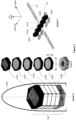
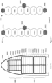
- FIG. 1 illustrates an example of a spacecraft configured as a self-assembling persistent space platform, according to an implementation.
- the spacecraft 100 illustrated in a launch configuration enclosed by a launch vehicle fairing, includes six deployable module elements 110.
- the deployable module element 110(1) may be configured as a bus service module
- each of the deployable module elements 110(2), 110(3), 110(4) and 110(5) may be configured as a respective payload module
- the deployable module element 110(6) may be configured as a propulsion module.
- the deployable modules may be configured to have a similar form factor where a height 'h' is small relative to width 'w'.
- 'h' may be approximately one meter and 'w' may be selected to maximize utilization of the launch vehicle fairing diameter, which may be approximately 4-5 meters.
- the deployable module elements have six edge faces, but a greater or smaller number of edge faces may be contemplated.
- the deployable module elements may have a cross-section having a square, rectangular or circular form factor.
- the deployable module elements may be disposed in a launch vehicle in a first arrangement.
- the first arrangement may be regarded as a "stacked arrangement".
- adjacent module elements may be mechanically coupled together.
- module element 110(1) may be mechanically coupled with module 110(2);
- module element 110(2) may be mechanically coupled with module element 110(1) and with module element 110(3);
- module element 110(3) may be mechanically coupled with module element 110(2) and with module element 110(4);
- module element 110(4) may be mechanically coupled with module element 110(3) and with module element 110(5);
- module element 110(5) may be mechanically coupled with module element 110(4) and with module element 110(6);
- module element 110(6) may be mechanically coupled with module element 110(5).
- the mechanical couplings may be releasable such that adjacent deployable modules may be separated from one another after launch.
- the mechanical couplings may be or include releasable holddowns or by an exoskeleton (not illustrated), as described, for example in U.S. Patent Application Serial No. 15/669,470 , entitled “MULTI-REFLECTOR HOLD-DOWN” and in U.S. Patent Application Serial No. 15/480,276 , entitled “EXOSKELETAL LAUNCH SUPPORT STRUCTURE".
- At least one of the deployable modules may include a robotic manipulator (not illustrated) operable to reconfigure (or "self-assemble") the spacecraft from the launch configuration to an on-orbit configuration.
- Detail C illustrates the spacecraft in an on-orbit configuration according to an implementation. It may be observed that, in the on-orbit configuration, the deployable modules are disposed in a second arrangement that may be regarded as a "side-by-side arrangement". In the on-orbit configuration, adjacent module elements may be mechanically coupled together.
- module element 110(2) may be mechanically coupled with module 110(3); module element 110(3) may be mechanically coupled with module element 110(2) and with module element 110(1); module element 110(1) may be mechanically coupled with module element 110(3) and with module element 110(4); module element 110(4) may be mechanically coupled with module element 110(1) and with module element 110(5); module element 110(5) may be mechanically coupled with module element 110(4).
- the mechanical couplings may be releasable such that adjacent deployable modules may be separated from one another in order to replace a defective module element or to otherwise reconfigure the spacecraft on-orbit.
- module element 110(1) which may be a bus service module that includes a solar array 111
- module 110(1) is centrally disposed, and is adjacent to two payload module elements, module element 110(4) and module element 110(5).
- the on-orbit configuration depicted in Detail C depicts a single linear row of module elements, the disclosed techniques contemplate more complex arrangements including multiple rows, and non-linear arrangements, for example.
- each of module elements 110(2), 110(3), 110(4) and 110(5) is a payload module element that includes two antenna reflectors 112. It will be appreciated that a payload element may be configured without an antenna reflector or with a number of reflectors different than two.
- FIG. 2 illustrates a view of the spacecraft 100 following separation from a launch vehicle.
- at least one deployable module element 110 includes a robotic manipulator 150, and each deployable module element 110 includes at least one grappling fixture 115.
- Some or all of the grappling fixtures 115 may provide an electrical power and/or telemetry/command interface between the manipulator 450 and module elements 110, in addition to a mechanical coupling between the module elements 110 and the manipulator 450.
- the mechanical coupling advantageously, may be engaged, disengaged, and reengaged any number of times.
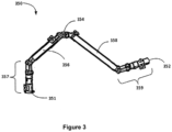
- the robotic manipulator may include a robotic arm having two end effectors and several articulable joints disposed therebetween.
- Manipulator 350 includes first and second longitudinally elongated arms 356 and 358. Respective proximal ends of the arms 356 and 358 may be coupled together by means of an elbow joint 354. Articulator 357 including one or more articulable joints may be coupled with a distal end of arm 356. Similarly, articulator 359 may be coupled with a distal end of arm 358.
- one or both of the articulator 357 and the articulator 359 includes a pitch joint, a yaw joint, and a roll joint.
- First and second end effectors 351 and 352 may be mounted at the respective distal ends of the articulators 357 and 359.
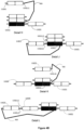
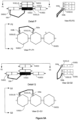
- FIGS 4A-4C illustrate techniques by which the satellite 100 is "self-assembled" into the on-orbit configuration.
- a manipulator 450 is used to move the plurality of deployable module elements 110 from the stacked launch configuration to the side-by-side on-orbit configuration.
- a configuration is illustrated that may occur as part of a transition between the launch configuration the on-orbit configuration.
- the module element 110(5) has been decoupled and moved away from the remainder of the stacked module elements by the manipulator 450.
- the manipulator 450 may include a proximal portion having a first end effector that has a mechanical coupling with one of the remainder of the stacked module elements.
- the mechanical coupling is by way of a grappling fixture 115.
- the manipulator 450 is mechanically coupled at the first end with bus services module 110(1).
- a distal portion of the manipulator 450 may include a second end effector that is detachably engaged with the deployable module element 110(5) by way of grappling fixture 115(5,1).
- the deployable module element 110(5) is depicted as having been translated and rotated, by the manipulator 450, with respect to the stack of remaining module elements toward a position consistent with a desired on-orbit configuration (Detail F).
- the manipulator 450 has positioned the deployable module element 110(5) proximate to a desired on-orbit location. More particularly, in the illustrated configuration, the deployable module element 110(5) has been positioned proximate to the bus services module element 110(1) such that it may be attached by way of grappling fixtures 115(1,1) and 115(5,1) as shown in Detail G.
- a mechanical coupling between the deployable module elements is depicted as being by way of grappling fixtures 115(1,1) and 115(5,1). In some implementations, however, a mechanical coupling arrangement may be provided between adjacent deployable modules in the on-orbit configuration that is different than the grappling fixtures 115.
- an electrical power and/or telemetry/command interface between the adjacent deployable modules is established at or about the time that a mechanical coupling is established.
- the manipulator 450 may be configured to attach the deployable module element 110(5) to the deployable module element 110(1). Subsequently, the second end effector of the manipulator 450 may be detached and separated from the grappling fixture 110(5,1) of the deployable module element 110(5) (Detail G).
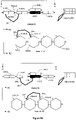
- a second deployable module element 110(4) is illustrated as having been uncoupled and moved away from the remainder of the module elements by the manipulator 450.
- the manipulator 450 has positioned the deployable module element 110 (4) proximate to the deployable module element 110(1) such that the deployable module element 110(4) and the deployable module element 110 (1) may be coupled together.
- the deployable payload module element 110(4) has been positioned proximate to the bus services module element 110(1) such that it may be attached by way of grappling fixtures 115(1,2) and 115(4,2) as shown in Detail J.
- a third deployable module element 110(3) is illustrated as having been uncoupled and moved away from the remainder of the module elements by the manipulator 450.
- the manipulator 450 has positioned the deployable module element 110(3) proximate to the deployable module element 110(4) such that the deployable module element 110(3) and the deployable module element 110 (4) may be coupled together. More particularly, in the illustrated configuration, the deployable payload module element 110(3) has been positioned proximate to the deployable payload module element 110(4) such that it may be attached by way of grappling fixtures 115(3,2) and 115(4,1) as shown in Detail L.
- a fourth deployable module element 110(2) is illustrated as having been uncoupled and moved away from the remainder of the module elements by the manipulator 450.
- the manipulator 450 has positioned the deployable module element 110(2) proximate to the deployable module element 110(5) such that the deployable module element 110(2) and the deployable module element 110 (5) may be coupled together. More particularly, in the illustrated configuration, the deployable payload module element 110(2) has been positioned proximate to the deployable payload module element 110(5) such that it may be attached by way of grappling fixtures 115(2,2) and 115(5,1) as shown in Detail N.
- solar arrays and antenna reflectors that may be coupled with the various module elements 110 are omitted. It will be appreciated however that one or more solar arrays at one or more antenna reflectors may be deployed at any stage of the self-assembly process illustrated in Figures 4A through 4C .
- the bus services module element 110(1) may be configured to interchangeably couple with various types of payload module elements. Moreover, in some implementations, the bus services module element 110(1) may be configured to provide a service life that is relatively long (15-20+ years) compared to the anticipated service life of the payload module elements. During the course of life of the bus services module element 110(1), it is contemplated that payload module elements deployed with or early in the life of the bus services module element 110(1) (“original payload module elements”) may become unreliable or obsolete. It is contemplated that such payload module elements may be "swapped out" with replacement payload module elements that are delivered to orbit subsequent to the initial launch of the s bus services module element 110(1).
- the replacement payload module elements may have an interchangeable mechanical and electrical interface as the original payload module element.
- the manipulator 450 may be used to decouple and separate a payload module element (that has become, for example, obsolete) and attach a replacement payload module. Consequently, it is contemplated that a persistent platform may be provided by a long-lived bus services module element 110(1).
- the propulsion module 110(6) may be configured as a separable stage including one or more chemical or electric thrusters.
- Chemical thrusters whether the propellant is solid or liquid, monopropellant or bipropellant, deliver thrust by converting chemical energy stored in the propellant to kinetic energy delivered to combustion products of the chemical propellant.
- Chemical thrusters as the term is used herein, and in the claims, also include electrothermal thrusters such as arc-jets that are configured to use electrical energy to increase the temperature, and, therefore, the velocity of the combustion products of chemical propellants.
- an electric thruster converts electrical energy to propellant kinetic energy substantially without regard to any chemical energy the propellant may possess.
- an electric thruster may operate by ionizing and accelerating a gaseous propellant, where the propellant is a heavy noble gas such as xenon or argon. Irrespective of the selected propellant, a negligible amount of thrust results from energy chemically stored in the propellant.
- the term electric thruster encompasses an electrostatic thruster, an electromagnetic thruster, a Hall Effect thruster, a Wakefield accelerator, and a traveling wave accelerator, for example.
- the propulsion module 110(6) may execute an orbit transfer strategy that transfers the satellite from a launch vehicle deployment orbit to an orbit (a "graveyard orbit") that is higher than GEO by a sufficient amount to provide a safe disposal of the propulsion module 110(6).
- the propulsion module 110(6) may be separated from the remainder of the spacecraft 100 in the graveyard orbit. Subsequently, the spacecraft 100 may be moved to GEO using, advantageously, electric thrusters disposed on one or more of the remaining deployable modules 110.
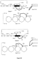
- FIGS 5A-5D illustrate techniques by which a satellite is "self-assembled" into the on-orbit configuration, in accordance with another implementation.
- a manipulator 550 is used to move a plurality of deployable module elements 510 from a stacked launch configuration to a side-by-side on-orbit configuration.
- a configuration is illustrated that may occur as part of a transition between the launch configuration the on-orbit configuration.
- a bus services module element 510(1) is depicted as being disposed between and side by side with deployable module elements 510(4) and 510(5).
- Two additional deployable module elements 510(2) and 510(3) are depicted as being disposed, stacked, above the bus services module element 510(1).
- the bus services module element 510(1) is attached to deployable module elements 510(4) and 510(5) by way of, respectively, grappling fixtures 515(1,2) and 515(1,1).
- a grappling fixture 515(1,3) is depicted as being coupled with a first end 550a of the manipulator 550.
- Each of the first end 550a and a second end 550b of the manipulator 550 may include an end effector configured to detachably couple with a respective grappling fixture.
- the mechanical coupling is by way of a grappling.
- the manipulator 550 is detachably engaged with the first end 550a with bus services module 110(1) by way of the grappling fixture 515(1,3), whereas the second end 550b of the manipulator 550 is detachably engaged with the deployable module element 510(4) by way of a grappling fixture 515(4,3).
- the manipulator 550 is illustrated as having been reconfigured so that the first end 550a has been detached from the grappling fixture 515(1,3) of bus services module element 510(1), and relocated so as to detachably engage with the module element 510(3) by way of a grappling fixture 515(3,3). It may also be observed that the module element 510(3) has been separated from the remaining module elements in the stack.
- the manipulator 550 has positioned the deployable module element 510(3) proximate to the deployable module element 510(4) such that the deployable module element 510(3) and the deployable module element 510 (4) may be coupled together. More particularly, in the illustrated configuration, the deployable payload module element 510(3) has been positioned proximate to the deployable payload module element 510(4) such that it may be attached by way of grappling fixtures 515(3,2) and 515(4,1) as shown in Detail R.
- the manipulator 550 is illustrated as having been reconfigured such that the first end 550a has been detached from the grappling fixture 515(3,3) of bus services module element 510(3) and relocated so as to detachably engage with the module element 510(1) by way of a grappling fixture 515(1,3).
- the manipulator 550 is illustrated as having been reconfigured such that the second end 550b has been detached from the grappling fixture 515(4,3) of bus services module element 510(4) and relocated so as to detachably engage with the module element 510(5) by way of a grappling fixture 515(5,3).
- the manipulator 550 is illustrated as having been reconfigured so that the first end 550a has been detached from the grappling fixture 515(1,3) of bus services module element 510(1), and relocated so as to detachably engage with the module element 510(2) by way of a grappling fixture 515(2,3). It may also be observed that the module element 510(2) has been separated from the bus services module element 510(1).
- the manipulator 550 has positioned the deployable module element 510(3) proximate to the deployable module element 510(5) such that the deployable module element 510(2) and the deployable module element 510(5) may be coupled together. More particularly, in the illustrated configuration, the deployable payload module element 510(2) has been positioned proximate to the deployable payload module element 510(5) such that it may be attached by way of grappling fixtures 515(3,2) and 515(4,1) as shown in Detail V.
- manipulator 550 is configured as self-relocatable manipulator, a substantially larger number of modules may be contemplated without a necessity to increase the size and mass of the manipulator 550.
- Figure 6 illustrates a process flow diagram for configuring a spacecraft for on-orbit operation.
- the spacecraft may include, in a launch configuration, a plurality of deployable module elements disposed in a launch vehicle in a stacked arrangement, the deployable module elements being disposed, in an on-orbit configuration, in a side-by-side arrangement.
- At least one of the deployable module elements may include a robotic manipulator operable to reconfigure the spacecraft from the launch configuration, through a transition configuration, to the on-orbit configuration.
- the method 600 may start, at block 610 with reconfiguring an orbiting spacecraft from a launch configuration to an on-orbit configuration.
- the method 600 may finish, at block 620, with operating the orbiting spacecraft in the on-orbit configuration.
- the reconfiguring step may be accomplished using a robotic manipulator, for example, a self-relocatable robotic arm.
- the capital expense required of payload service providers may be substantially reduced by providing, under a contractual arrangement, housekeeping services by way of a persistent space-based infrastructure module.
- the arrangement may be referred to as a "condominium" spacecraft infrastructure, in view of the fact that at least some of the bus services may be shared by payload modules owned and/or operated by separate parties who may be otherwise unrelated.
- the infrastructure module may be detachably coupled with one or more of the payload modules and that a payload module may be replaced or interchanged from time to time during the operational life of the infrastructure module.
- the bus services may include, for example, electrical power, telemetry and command interfaces with a ground station, attitude control and orbit control.
- the bus services module may be designed to provide substantially more service capacity than would be required by any single payload module, and to have a substantially longer operational life than at least some payload modules.
- the bus services may be provided under a contract between a first party which is the owner/operator of the infrastructure module and a second party which is an owner/operator of at least one of payload services modules.
- the contract may be in the form of a lease, in some implementations; however, other contractual schemes may be contemplated.
- two or more owner/operators of payload services modules may form a joint venture or similar business entity that finances and owns/operates the infrastructure module and rents or leases bus services to the two or more owner/operators of payload services modules and/or to other owner/operators of payload services modules.
- the infrastructure module may be deployed into space at a substantially earlier time than at least one of the one or more payload modules.
- the disclosed techniques are compatible with non-simultaneous (asynchronous) launch of independent modules that are then assembled on-orbit.
- the infrastructure module may be configured to be expanded and/or refurbished to accommodate, over its mission lifetime, possible changes in requirements for bus services.
- the infrastructure functions may be physically contained in one or more infrastructure module(s) that may be separate from and detachably coupled with the mission payload modules, at least some of which may be owned/operated by a different entity than that which owns/operates the infrastructure modules.
- no dedicated or permanent connection necessarily exists between respective diverse owner/operators of the payload modules and the infrastructure module(s).
- a satellite services "space real estate" business model may be implemented in which bus services may be "for rent or lease" by a number of diverse mission payloads.
- a commercial business entity may deploy an infrastructure module and lease services to mission payload owners.
- the commercial business entity may also own/operate one or more payload modules. Whether or not this is so, the mission payload owners receiving leased services may benefit from a substantial reduction in initial capital expense.
- the disclosed techniques allow mission payloads to be replaced so that a single mission payload need not carry the full cost burden of the infrastructure for the entire service life of the infrastructure elements. This further reduces the cost burden, particularly where the expected service life of a payload module is less than that of the infrastructure module.
- FIG. 7 illustrates a process flow diagram for providing bus services to one or more replaceable payload modules, according to an implementation.
- the method 700 may start, at block 710, with operating an earth orbiting persistent infrastructure module.
- the infrastructure module may be configured to provide housekeeping subsystems, such as electrical power, telemetry and command, and attitude and orbit control subsystems.
- the infrastructure module may be detachably coupled with the replaceable payload modules.
- the method 700 may finish, at block 720, with providing bus services from the infrastructure module to the replaceable payload modules.
- the bus services may be provided under a contract between a first owner/operator of the infrastructure module and a second owner/operator of at least one of the one or more payload services modules.
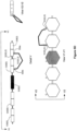
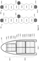
- FIG. 8 illustrates a launch vehicle payload including a robotic manipulator and a payload stack, in accordance with an implementation.
- a payload stack in the launch configuration includes a lower (or aft) portion 800A of the stack that includes a first spacecraft 801 and a second spacecraft 802.
- the second spacecraft 802 is disposed forward of the first spacecraft 801.
- the payload stack also includes an upper (or forward) portion 800F that includes a number of deployable module elements 830.
- deployable module elements 830 may, following launch, be relocated from the stacked launch configuration of Detail W to an on-orbit arrangement (Detail AB) in which at least one deployable module 830 is coupled with the first spacecraft 801.
- FIG. X shows that the modules 830 may be individually removed from the stack and manipulated one at a time.
- Detail Y shows that the first deployable module removed, 830(6) may be disposed in a temporary stow location.
- deployable module 830(6) is temporarily disposed near an aft surface of the first spacecraft 801.
- Detail Z shows an in interim arrangement in which deployable modules 830(1), 830(2) and 830(3) are disposed in an on-orbit configuration coupled with the second spacecraft 802 and in which deployable modules 830(4) and 830(5) are disposed in an on-orbit configuration coupled with the first spacecraft 801.
- Detail AA illustrates a configuration in which the first spacecraft 801 has been separated from the second spacecraft 802. As a result of the separation, a forward surface of first spacecraft 801, previously proximate to an aft surface of spacecraft 802 becomes accessible.
- Detail AB an on-orbit configuration that may result from the mechanical arm repositioning module 830(6) from the aft surface of spacecraft 801 to the forward surface of spacecraft 801.
- the deployable module elements 830 may be characteristically smaller in size than the spacecraft 801 and 802, particularly in a dimension transverse to a longitudinal axis of the fairing 10000.
- a total "stack height" of the launch vehicle payload may be increased, because the deployable module elements 830 fit within a tapered forward section of the launch vehicle fairing that is not large enough to accommodate the spacecraft 801 or the spacecraft 802.
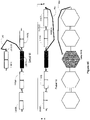
- FIG. 9 illustrates a launch vehicle payload, in accordance with another implementation.
- a lower (or aft) portion 900A of the stack includes a first plurality of deployable module elements 910 associated with a first spacecraft 901 and a second plurality of deployable module elements 920 associated with a spacecraft 902.
- the deployable modules 910 and 920 are stacked, in a launch configuration, together with a third plurality of deployable modules 930 for launch by a single launch vehicle.
- the deployable modules 930 are disposed, in the launch configuration, in an upper (or forward) portion 900F of the stack.
- deployable module elements 910 and 920 may, following launch, be reconfigured from the stacked launch configuration of Detail AC to a side-by-side on-orbit configuration (Detail AD).
- One or more of the deployable module elements 910 and 920 may include robotic manipulators (not shown) to facilitate this reconfiguration.
- each deployable module elements 910 and six each deployable modules 920 are each located in the lower portion 900A of the stack.
- a first portion of the third plurality of deployable modules 930 may be associated with the spacecraft 901 and a second portion of the third plurality of deployable module elements 930 may be associated with the spacecraft 902.
- deployable module elements 930(1), 930(2), and 930(3) are associated with the spacecraft 901 while deployable module elements 830(4), 830(5), and 830(6) are associated with the spacecraft 902.
- deployable module elements 930(1), 930(2), and 930(3) are coupled with the deployable module elements 910 of the spacecraft 901 while deployable module elements 930(4), 930(5), and 930(6) are coupled with the deployable module elements 920 of the spacecraft 902.
- the deployable module elements 930 may be characteristically smaller than deployable module elements 910 and 920.
- the deployable module elements 930 may have a characteristic dimension ⁇ 1 , transverse to a longitudinal axis of the fairing 10000, whereas the deployable module elements 910 and/or 920 have a characteristic dimension ⁇ 2 transverse to the longitudinal axis of the fairing 10000.
- the characteristic dimension ⁇ 2 may be substantially larger than the characteristic dimension ⁇ 1 .
- ⁇ 2 may be 20% or more larger than ⁇ 1 .
- a total "stack height" of the launch vehicle payload may be increased, because the deployable module elements 930 fit within a tapered forward section of the launch vehicle fairing that has a diameter smaller than ⁇ 2 .
- the present disclosure contemplates more efficient use of the volume within launch vehicle fairing 10000.
- the relatively small deployable module elements 830 may be lower mass than the relatively large deployable module elements 810 and/or 820, placing the small deployable module elements 830 on top of the stack may, advantageously, reduce the height of the center of gravity of the launch vehicle payload.
- the first plurality of deployable module elements 910 associated with a spacecraft 901 are depicted as being disposed in a lower region of the aft portion 900A whereas the second plurality of deployable module elements 920 associated with a spacecraft 902 are depicted as being disposed in an upper region of the aft portion 900A.
- each of the deployable module elements 920 is disposed forward of all of the deployable module elements 910.
- Figure 10 illustrates a launch vehicle payload including a stack of deployable module elements in accordance with another implementation.
- an aft portion 1000A of the stack includes least one of the deployable module elements 1010 being disposed forward of a first subset of the deployable module elements 1020 and aft of a second subset of the deployable modules1020. More particularly, in the illustrated example, it may be observed that deployable module element 1010(2) is disposed forward of deployable module element 1020(1) and aft of deployable module 1020(2).
- the illustrated implementation may be advantageous for purposes of improving mass properties of the stack. For example, it is often desirable to minimize the height of the center of gravity of the stack. Accordingly, the deployable modules having the greatest mass are advantageously located near the bottom of the stack.
Landscapes
- Engineering & Computer Science (AREA)
- Remote Sensing (AREA)
- Aviation & Aerospace Engineering (AREA)
- Physics & Mathematics (AREA)
- Astronomy & Astrophysics (AREA)
- General Physics & Mathematics (AREA)
- Manipulator (AREA)
Claims (4)
- Raumfahrzeug (100), das umfasst:eine Mehrzahl von einsetzbaren Modulelementen (110), wobei zumindest eines der einsetzbaren Modulelemente einen Robotermanipulator (150) beinhaltet, wobei das Raumfahrzeug (100) aus einer Startkonfiguration in eine In-der-Umlaufbahn-Konfiguration rekonfigurierbar ist, wobei:die einsetzbaren Modulelemente (110) in der Startkonfiguration so konfiguriert sind, dass sie in einer Trägerrakete in einer ersten Anordnung angeordnet sind;die einsetzbaren Modulelemente (110) in der In-der-Umlaufbahn-Konfiguration in einer zweiten Anordnung angeordnet sind; unddas Raumfahrzeug (110) so konfiguriert ist, dass es von dem Robotermanipulator (150) selbst arrangiert wird, wobei das Raumfahrzeug aus der Startkonfiguration über eine Übergangskonfiguration in die In-der-Umlaufbahn-Konfiguration rekonfiguriert wird;benachbarte der einsetzbaren Modulelemente in der Startkonfiguration lösbar mit einer ersten lösbaren Kopplung gekoppelt sind;die benachbarten der einsetzbaren Modulelemente (110) in der In-der-Umlaufbahn-Konfiguration lösbar mit einer zweiten lösbaren Kopplung gekoppelt sind, die sich von der ersten lösbaren Kopplung unterscheidet; undsowohl die erste lösbare Kopplung als auch die zweite lösbare Kopplung in der Übergangskonfiguration gelöst sind; unddie Mehrzahl von einsetzbaren Modulelementen zumindest ein Buswartungsmodul, zumindest ein Antriebsmodul und zumindest zwei ersetzbare Nutzlastmodule beinhaltet.
- Raumfahrzeug nach Anspruch 1, wobei:die einsetzbaren Modulelemente (110) in der Startkonfiguration gestapelt angeordnet sind; unddie einsetzbaren Modulelemente (110) in der In-der-Umlaufbahn-Konfiguration nebeneinander angeordnet sind.
- Verfahren, das umfasst:Selbstarrangieren eines umlaufenden Raumfahrzeuges (100) aus einer Startkonfiguration in eine In-der-Umlaufbahn-Konfiguration; undBetreiben des umlaufenden Raumfahrzeugs (100) in der In-der-Umlaufbahn-Konfiguration, wobei:eine Mehrzahl von einsetzbaren Modulelementen (110) in der Startkonfiguration in einer Trägerrakete gestapelt angeordnet sind; unddie einsetzbaren Modulelemente (110) in der In-der-Umlaufbahn-Konfiguration nebeneinander angeordnet sind; undzumindest eines der einsetzbaren Modulelemente (110) einen Robotermanipulator (150) beinhaltet, der so betreibbar ist, dass er das umlaufende Raumfahrzeug aus der Startkonfiguration über eine Übergangskonfiguration in die In-der-Umlaufbahn-Konfiguration rekonfiguriert;benachbarte der einsetzbaren Modulelemente (110) in der gestapelten Anordnung lösbar mit einer ersten lösbaren Kopplung gekoppelt sind;die benachbarten der einsetzbaren Modulelemente in der Nebeneinander-Anordnung lösbar mit einer zweiten lösbaren Kopplung gekoppelt sind; undsowohl die erste lösbare Kopplung als auch die zweite lösbare Kopplung in der Übergangskonfiguration gelöst sind; und
die Mehrzahl von einsetzbaren Modulelementen zumindest ein Buswartungsmodul, zumindest ein Antriebsmodul und zumindest zwei ersetzbare Nutzlastmodule beinhaltet. - Verfahren nach Anspruch 3, wobei das Selbstarrangieren des umlaufenden Raumfahrzeugs das Verwenden des Robotermanipulators (150) zum Rekonfigurieren des Raumfahrzeugs aus der Startkonfiguration über die Übergangskonfiguration in die In-der-Umlaufbahn-Konfiguration beinhaltet.
Applications Claiming Priority (3)
| Application Number | Priority Date | Filing Date | Title |
|---|---|---|---|
| US201662404113P | 2016-10-04 | 2016-10-04 | |
| US201762506522P | 2017-05-15 | 2017-05-15 | |
| US15/689,993 US10661918B2 (en) | 2016-10-04 | 2017-08-29 | Self-assembling persistent space platform |
Publications (2)
| Publication Number | Publication Date |
|---|---|
| EP3305666A1 EP3305666A1 (de) | 2018-04-11 |
| EP3305666B1 true EP3305666B1 (de) | 2023-02-22 |
Family
ID=59923344
Family Applications (1)
| Application Number | Title | Priority Date | Filing Date |
|---|---|---|---|
| EP17192203.2A Active EP3305666B1 (de) | 2016-10-04 | 2017-09-20 | Raumfahrzeug, verfahren und system |
Country Status (2)
| Country | Link |
|---|---|
| US (2) | US10661918B2 (de) |
| EP (1) | EP3305666B1 (de) |
Families Citing this family (14)
| Publication number | Priority date | Publication date | Assignee | Title |
|---|---|---|---|---|
| US10351268B2 (en) | 2016-12-08 | 2019-07-16 | The Boeing Company | Systems and methods for deploying spacecraft |
| US10435183B1 (en) * | 2017-04-14 | 2019-10-08 | Space Systems/Loral, Llc | Deployable propulsion module for spacecraft |
| WO2020261397A1 (ja) | 2019-06-25 | 2020-12-30 | 三菱電機株式会社 | デブリ回収制御装置、デブリ回収衛星、捕獲用インタフェース機器、接続装置、デブリ回収システム、デブリ回収方法、および、デブリ回収プログラム |
| US11492147B2 (en) * | 2020-07-30 | 2022-11-08 | The Aerospace Corporation | Stackable satellite structure and deployment method |
| US11780611B2 (en) | 2020-09-16 | 2023-10-10 | Maxar Space Llc | Spacecraft with universal external port |
| CN112265656B (zh) * | 2020-09-23 | 2021-12-07 | 北京空间飞行器总体设计部 | 面向大长度天线的集装收纳式在轨组装装置及方法 |
| CN113650807B (zh) * | 2021-03-26 | 2023-11-10 | 中国空间技术研究院 | 一种适于多层叠放的开敞式卫星构型 |
| CN113581502B (zh) * | 2021-08-11 | 2023-05-26 | 哈尔滨工业大学 | 基于多空间机器人系统的超大型太空望远镜在轨组装方法 |
| IT202100023324A1 (it) * | 2021-09-09 | 2023-03-09 | Newroboticarm S R L S | Struttura di satellite |
| CN114368495A (zh) * | 2022-03-22 | 2022-04-19 | 中国人民解放军战略支援部队航天工程大学 | 一种用于多体卫星扭转弯曲变构的二自由度一体化关节 |
| CN115837987B (zh) * | 2022-11-16 | 2025-12-12 | 中国空间技术研究院 | 一种支持在轨组装的模块化可重构卫星平台 |
| US12600497B2 (en) * | 2023-07-17 | 2026-04-14 | Maxar Space Llc | Linked spacecraft dispensing |
| US12214909B1 (en) * | 2023-07-17 | 2025-02-04 | Maxar Space Llc | Dispensing hinge assembly |
| FR3163351A1 (fr) * | 2024-06-13 | 2025-12-19 | Thales | Plateforme spatiale et procédé de déploiement d’une telle plateforme |
Family Cites Families (23)
| Publication number | Priority date | Publication date | Assignee | Title |
|---|---|---|---|---|
| US4725025A (en) | 1986-03-21 | 1988-02-16 | Rca Corporation | Deployment system |
| US4832113A (en) | 1988-03-11 | 1989-05-23 | The United States Of America As Represented By The United States Department Of Energy | Survivable pulse power space radiator |
| US5052640A (en) * | 1989-08-29 | 1991-10-01 | Hughes Aircraft Company | Spacecraft design enabling the flat packing of multiple spacecraft in the launch vehicle |
| US5114101A (en) * | 1989-09-28 | 1992-05-19 | General Dynamics Corporation/Space Systems Division | Modular distributed concentrating collector using power bus to route power to centralized converter |
| US5145130A (en) | 1991-10-23 | 1992-09-08 | The United States Of America As Represented By The Administrator Of The National Aeronautics & Space Administration | Robot serviced space facility |
| EP0541052B1 (de) | 1991-11-05 | 1996-02-07 | Hitachi, Ltd. | System von Raumfahrzeugen |
| JPH05278695A (ja) | 1992-04-03 | 1993-10-26 | Shimizu Corp | 宇宙大型構造物の構築方法 |
| US5527001A (en) * | 1993-06-11 | 1996-06-18 | Teledesic Corporation | Modular communication satellite |
| US5644322A (en) | 1995-06-16 | 1997-07-01 | Space Systems/Loral, Inc. | Spacecraft antenna reflectors and stowage and restraint system therefor |
| US5785280A (en) * | 1995-07-20 | 1998-07-28 | Space Systems/Loral, Inc. | Hybrid solar panel array |
| US6568638B1 (en) * | 2000-11-07 | 2003-05-27 | Lockheed Martin Corporation | Modular spacecraft structure |
| US6448940B1 (en) | 2001-03-20 | 2002-09-10 | Space Systems/Loral, Inc. | Triple reflector antenna deployment and storage systems |
| JP3981727B2 (ja) | 2002-12-17 | 2007-09-26 | 独立行政法人 宇宙航空研究開発機構 | 組立部材収納装置 |
| ES2539205T3 (es) | 2004-04-08 | 2015-06-26 | Astrium Limited | Mástil desplegable |
| US7478782B2 (en) | 2004-11-16 | 2009-01-20 | The Boeing Company | System and method incorporating adaptive and reconfigurable cells |
| US7714797B2 (en) * | 2005-03-04 | 2010-05-11 | Astrium Limited | Phased array antenna |
| FR2902763B1 (fr) | 2006-06-23 | 2009-05-22 | Alcatel Sa | Articulation auto-motorisee pour ensemble articule tel qu'un panneau solaire de satellite |
| US8789796B2 (en) | 2010-09-16 | 2014-07-29 | Space Systems/Loral, Llc | High capacity broadband satellite |
| FR2969579B1 (fr) | 2010-12-23 | 2013-08-16 | Thales Sa | Grandes structures rigides deployables et procede de deploiement et de verrouillage de telles structures |
| US8448902B2 (en) | 2011-02-11 | 2013-05-28 | Space Systems/Loral LLC | Satellite having multiple aspect ratios |
| FR3015955B1 (fr) * | 2013-12-30 | 2016-12-30 | Astrium Sas | Structure segmentee, en particulier pour reflecteur d'antenne de satellite, pourvue d'au moins un dispositif de deploiement a rotation et translation |
| US9878806B2 (en) | 2015-03-09 | 2018-01-30 | Space Systems/Loral, Llc | On-orbit assembly of communication satellites |
| US20180201393A1 (en) * | 2017-01-18 | 2018-07-19 | Cory Lawrence Johns | Apparatus and method for packaging and deploying large structures using hexagons |
-
2017
- 2017-08-29 US US15/689,993 patent/US10661918B2/en active Active
- 2017-09-20 EP EP17192203.2A patent/EP3305666B1/de active Active
-
2020
- 2020-04-22 US US16/855,356 patent/US20200247563A1/en not_active Abandoned
Also Published As
| Publication number | Publication date |
|---|---|
| US10661918B2 (en) | 2020-05-26 |
| US20180093786A1 (en) | 2018-04-05 |
| EP3305666A1 (de) | 2018-04-11 |
| US20200247563A1 (en) | 2020-08-06 |
Similar Documents
| Publication | Publication Date | Title |
|---|---|---|
| EP3305666B1 (de) | Raumfahrzeug, verfahren und system | |
| JP7297988B2 (ja) | 宇宙船作業用デバイス、ならびに関連の組立体、システム、および方法 | |
| EP3268282B1 (de) | Umlaufbahnmontage von kommunikationssatelliten | |
| CN113631481B (zh) | 航天器服务装置及相关组件、系统和方法 | |
| US7163179B1 (en) | Commercial service platform in space | |
| EP3385173B1 (de) | Raumfahrzeug, system und verfahren zum einsetzen eines raumfahrzeugs | |
| EP3289313B1 (de) | System und verfahren zum montieren und einsetzen von satelliten | |
| US9796484B2 (en) | Satellite system comprising two satellites attached to each other and method for launching them into orbit | |
| US10435183B1 (en) | Deployable propulsion module for spacecraft | |
| WO2023025942A1 (en) | Method and system for a scalable and reconfigurable space infrastructure | |
| JPWO2020150242A5 (de) | ||
| WO2025198643A2 (en) | Reusable and reconfigurable launch vehicle | |
| Rey et al. | Extra-vehicular robotic maintenance for the International Space Station (ISS) and applications to space exploration | |
| Kleinau et al. | European orbit transfer and servicing vehicle approaches (survey) |
Legal Events
| Date | Code | Title | Description |
|---|---|---|---|
| PUAI | Public reference made under article 153(3) epc to a published international application that has entered the european phase |
Free format text: ORIGINAL CODE: 0009012 |
|
| STAA | Information on the status of an ep patent application or granted ep patent |
Free format text: STATUS: THE APPLICATION HAS BEEN PUBLISHED |
|
| AK | Designated contracting states |
Kind code of ref document: A1 Designated state(s): AL AT BE BG CH CY CZ DE DK EE ES FI FR GB GR HR HU IE IS IT LI LT LU LV MC MK MT NL NO PL PT RO RS SE SI SK SM TR |
|
| AX | Request for extension of the european patent |
Extension state: BA ME |
|
| STAA | Information on the status of an ep patent application or granted ep patent |
Free format text: STATUS: REQUEST FOR EXAMINATION WAS MADE |
|
| 17P | Request for examination filed |
Effective date: 20181009 |
|
| RBV | Designated contracting states (corrected) |
Designated state(s): AL AT BE BG CH CY CZ DE DK EE ES FI FR GB GR HR HU IE IS IT LI LT LU LV MC MK MT NL NO PL PT RO RS SE SI SK SM TR |
|
| STAA | Information on the status of an ep patent application or granted ep patent |
Free format text: STATUS: EXAMINATION IS IN PROGRESS |
|
| 17Q | First examination report despatched |
Effective date: 20201203 |
|
| GRAP | Despatch of communication of intention to grant a patent |
Free format text: ORIGINAL CODE: EPIDOSNIGR1 |
|
| STAA | Information on the status of an ep patent application or granted ep patent |
Free format text: STATUS: GRANT OF PATENT IS INTENDED |
|
| INTG | Intention to grant announced |
Effective date: 20221110 |
|
| GRAS | Grant fee paid |
Free format text: ORIGINAL CODE: EPIDOSNIGR3 |
|
| GRAA | (expected) grant |
Free format text: ORIGINAL CODE: 0009210 |
|
| STAA | Information on the status of an ep patent application or granted ep patent |
Free format text: STATUS: THE PATENT HAS BEEN GRANTED |
|
| AK | Designated contracting states |
Kind code of ref document: B1 Designated state(s): AL AT BE BG CH CY CZ DE DK EE ES FI FR GB GR HR HU IE IS IT LI LT LU LV MC MK MT NL NO PL PT RO RS SE SI SK SM TR |
|
| REG | Reference to a national code |
Ref country code: GB Ref legal event code: FG4D |
|
| REG | Reference to a national code |
Ref country code: CH Ref legal event code: EP |
|
| REG | Reference to a national code |
Ref country code: AT Ref legal event code: REF Ref document number: 1549356 Country of ref document: AT Kind code of ref document: T Effective date: 20230315 Ref country code: IE Ref legal event code: FG4D |
|
| REG | Reference to a national code |
Ref country code: DE Ref legal event code: R096 Ref document number: 602017066164 Country of ref document: DE |
|
| REG | Reference to a national code |
Ref country code: LT Ref legal event code: MG9D |
|
| REG | Reference to a national code |
Ref country code: NL Ref legal event code: MP Effective date: 20230222 |
|
| P01 | Opt-out of the competence of the unified patent court (upc) registered |
Effective date: 20230528 |
|
| REG | Reference to a national code |
Ref country code: AT Ref legal event code: MK05 Ref document number: 1549356 Country of ref document: AT Kind code of ref document: T Effective date: 20230222 |
|
| PG25 | Lapsed in a contracting state [announced via postgrant information from national office to epo] |
Ref country code: RS Free format text: LAPSE BECAUSE OF FAILURE TO SUBMIT A TRANSLATION OF THE DESCRIPTION OR TO PAY THE FEE WITHIN THE PRESCRIBED TIME-LIMIT Effective date: 20230222 Ref country code: PT Free format text: LAPSE BECAUSE OF FAILURE TO SUBMIT A TRANSLATION OF THE DESCRIPTION OR TO PAY THE FEE WITHIN THE PRESCRIBED TIME-LIMIT Effective date: 20230622 Ref country code: NO Free format text: LAPSE BECAUSE OF FAILURE TO SUBMIT A TRANSLATION OF THE DESCRIPTION OR TO PAY THE FEE WITHIN THE PRESCRIBED TIME-LIMIT Effective date: 20230522 Ref country code: NL Free format text: LAPSE BECAUSE OF FAILURE TO SUBMIT A TRANSLATION OF THE DESCRIPTION OR TO PAY THE FEE WITHIN THE PRESCRIBED TIME-LIMIT Effective date: 20230222 Ref country code: LV Free format text: LAPSE BECAUSE OF FAILURE TO SUBMIT A TRANSLATION OF THE DESCRIPTION OR TO PAY THE FEE WITHIN THE PRESCRIBED TIME-LIMIT Effective date: 20230222 Ref country code: LT Free format text: LAPSE BECAUSE OF FAILURE TO SUBMIT A TRANSLATION OF THE DESCRIPTION OR TO PAY THE FEE WITHIN THE PRESCRIBED TIME-LIMIT Effective date: 20230222 Ref country code: HR Free format text: LAPSE BECAUSE OF FAILURE TO SUBMIT A TRANSLATION OF THE DESCRIPTION OR TO PAY THE FEE WITHIN THE PRESCRIBED TIME-LIMIT Effective date: 20230222 Ref country code: ES Free format text: LAPSE BECAUSE OF FAILURE TO SUBMIT A TRANSLATION OF THE DESCRIPTION OR TO PAY THE FEE WITHIN THE PRESCRIBED TIME-LIMIT Effective date: 20230222 Ref country code: AT Free format text: LAPSE BECAUSE OF FAILURE TO SUBMIT A TRANSLATION OF THE DESCRIPTION OR TO PAY THE FEE WITHIN THE PRESCRIBED TIME-LIMIT Effective date: 20230222 |
|
| PG25 | Lapsed in a contracting state [announced via postgrant information from national office to epo] |
Ref country code: SE Free format text: LAPSE BECAUSE OF FAILURE TO SUBMIT A TRANSLATION OF THE DESCRIPTION OR TO PAY THE FEE WITHIN THE PRESCRIBED TIME-LIMIT Effective date: 20230222 Ref country code: PL Free format text: LAPSE BECAUSE OF FAILURE TO SUBMIT A TRANSLATION OF THE DESCRIPTION OR TO PAY THE FEE WITHIN THE PRESCRIBED TIME-LIMIT Effective date: 20230222 Ref country code: IS Free format text: LAPSE BECAUSE OF FAILURE TO SUBMIT A TRANSLATION OF THE DESCRIPTION OR TO PAY THE FEE WITHIN THE PRESCRIBED TIME-LIMIT Effective date: 20230622 Ref country code: GR Free format text: LAPSE BECAUSE OF FAILURE TO SUBMIT A TRANSLATION OF THE DESCRIPTION OR TO PAY THE FEE WITHIN THE PRESCRIBED TIME-LIMIT Effective date: 20230523 Ref country code: FI Free format text: LAPSE BECAUSE OF FAILURE TO SUBMIT A TRANSLATION OF THE DESCRIPTION OR TO PAY THE FEE WITHIN THE PRESCRIBED TIME-LIMIT Effective date: 20230222 |
|
| PG25 | Lapsed in a contracting state [announced via postgrant information from national office to epo] |
Ref country code: SM Free format text: LAPSE BECAUSE OF FAILURE TO SUBMIT A TRANSLATION OF THE DESCRIPTION OR TO PAY THE FEE WITHIN THE PRESCRIBED TIME-LIMIT Effective date: 20230222 Ref country code: RO Free format text: LAPSE BECAUSE OF FAILURE TO SUBMIT A TRANSLATION OF THE DESCRIPTION OR TO PAY THE FEE WITHIN THE PRESCRIBED TIME-LIMIT Effective date: 20230222 Ref country code: EE Free format text: LAPSE BECAUSE OF FAILURE TO SUBMIT A TRANSLATION OF THE DESCRIPTION OR TO PAY THE FEE WITHIN THE PRESCRIBED TIME-LIMIT Effective date: 20230222 Ref country code: DK Free format text: LAPSE BECAUSE OF FAILURE TO SUBMIT A TRANSLATION OF THE DESCRIPTION OR TO PAY THE FEE WITHIN THE PRESCRIBED TIME-LIMIT Effective date: 20230222 Ref country code: CZ Free format text: LAPSE BECAUSE OF FAILURE TO SUBMIT A TRANSLATION OF THE DESCRIPTION OR TO PAY THE FEE WITHIN THE PRESCRIBED TIME-LIMIT Effective date: 20230222 |
|
| REG | Reference to a national code |
Ref country code: DE Ref legal event code: R097 Ref document number: 602017066164 Country of ref document: DE |
|
| PG25 | Lapsed in a contracting state [announced via postgrant information from national office to epo] |
Ref country code: SK Free format text: LAPSE BECAUSE OF FAILURE TO SUBMIT A TRANSLATION OF THE DESCRIPTION OR TO PAY THE FEE WITHIN THE PRESCRIBED TIME-LIMIT Effective date: 20230222 |
|
| PLBE | No opposition filed within time limit |
Free format text: ORIGINAL CODE: 0009261 |
|
| STAA | Information on the status of an ep patent application or granted ep patent |
Free format text: STATUS: NO OPPOSITION FILED WITHIN TIME LIMIT |
|
| 26N | No opposition filed |
Effective date: 20231123 |
|
| PG25 | Lapsed in a contracting state [announced via postgrant information from national office to epo] |
Ref country code: SI Free format text: LAPSE BECAUSE OF FAILURE TO SUBMIT A TRANSLATION OF THE DESCRIPTION OR TO PAY THE FEE WITHIN THE PRESCRIBED TIME-LIMIT Effective date: 20230222 |
|
| REG | Reference to a national code |
Ref country code: DE Ref legal event code: R119 Ref document number: 602017066164 Country of ref document: DE |
|
| REG | Reference to a national code |
Ref country code: CH Ref legal event code: PL |
|
| PG25 | Lapsed in a contracting state [announced via postgrant information from national office to epo] |
Ref country code: LU Free format text: LAPSE BECAUSE OF NON-PAYMENT OF DUE FEES Effective date: 20230920 |
|
| REG | Reference to a national code |
Ref country code: BE Ref legal event code: MM Effective date: 20230930 |
|
| GBPC | Gb: european patent ceased through non-payment of renewal fee |
Effective date: 20230920 |
|
| PG25 | Lapsed in a contracting state [announced via postgrant information from national office to epo] |
Ref country code: LU Free format text: LAPSE BECAUSE OF NON-PAYMENT OF DUE FEES Effective date: 20230920 Ref country code: IT Free format text: LAPSE BECAUSE OF FAILURE TO SUBMIT A TRANSLATION OF THE DESCRIPTION OR TO PAY THE FEE WITHIN THE PRESCRIBED TIME-LIMIT Effective date: 20230222 Ref country code: MC Free format text: LAPSE BECAUSE OF FAILURE TO SUBMIT A TRANSLATION OF THE DESCRIPTION OR TO PAY THE FEE WITHIN THE PRESCRIBED TIME-LIMIT Effective date: 20230222 |
|
| REG | Reference to a national code |
Ref country code: IE Ref legal event code: MM4A |
|
| PG25 | Lapsed in a contracting state [announced via postgrant information from national office to epo] |
Ref country code: IE Free format text: LAPSE BECAUSE OF NON-PAYMENT OF DUE FEES Effective date: 20230920 |
|
| PG25 | Lapsed in a contracting state [announced via postgrant information from national office to epo] |
Ref country code: GB Free format text: LAPSE BECAUSE OF NON-PAYMENT OF DUE FEES Effective date: 20230920 |
|
| PG25 | Lapsed in a contracting state [announced via postgrant information from national office to epo] |
Ref country code: CH Free format text: LAPSE BECAUSE OF NON-PAYMENT OF DUE FEES Effective date: 20230930 |
|
| PG25 | Lapsed in a contracting state [announced via postgrant information from national office to epo] |
Ref country code: IE Free format text: LAPSE BECAUSE OF NON-PAYMENT OF DUE FEES Effective date: 20230920 Ref country code: GB Free format text: LAPSE BECAUSE OF NON-PAYMENT OF DUE FEES Effective date: 20230920 Ref country code: DE Free format text: LAPSE BECAUSE OF NON-PAYMENT OF DUE FEES Effective date: 20240403 Ref country code: CH Free format text: LAPSE BECAUSE OF NON-PAYMENT OF DUE FEES Effective date: 20230930 |
|
| PG25 | Lapsed in a contracting state [announced via postgrant information from national office to epo] |
Ref country code: BE Free format text: LAPSE BECAUSE OF NON-PAYMENT OF DUE FEES Effective date: 20230930 |
|
| PG25 | Lapsed in a contracting state [announced via postgrant information from national office to epo] |
Ref country code: BG Free format text: LAPSE BECAUSE OF FAILURE TO SUBMIT A TRANSLATION OF THE DESCRIPTION OR TO PAY THE FEE WITHIN THE PRESCRIBED TIME-LIMIT Effective date: 20230222 |
|
| PG25 | Lapsed in a contracting state [announced via postgrant information from national office to epo] |
Ref country code: BG Free format text: LAPSE BECAUSE OF FAILURE TO SUBMIT A TRANSLATION OF THE DESCRIPTION OR TO PAY THE FEE WITHIN THE PRESCRIBED TIME-LIMIT Effective date: 20230222 |
|
| PG25 | Lapsed in a contracting state [announced via postgrant information from national office to epo] |
Ref country code: CY Free format text: LAPSE BECAUSE OF FAILURE TO SUBMIT A TRANSLATION OF THE DESCRIPTION OR TO PAY THE FEE WITHIN THE PRESCRIBED TIME-LIMIT; INVALID AB INITIO Effective date: 20170920 |
|
| PG25 | Lapsed in a contracting state [announced via postgrant information from national office to epo] |
Ref country code: HU Free format text: LAPSE BECAUSE OF FAILURE TO SUBMIT A TRANSLATION OF THE DESCRIPTION OR TO PAY THE FEE WITHIN THE PRESCRIBED TIME-LIMIT; INVALID AB INITIO Effective date: 20170920 |
|
| PGFP | Annual fee paid to national office [announced via postgrant information from national office to epo] |
Ref country code: FR Payment date: 20250708 Year of fee payment: 9 |
|
| PG25 | Lapsed in a contracting state [announced via postgrant information from national office to epo] |
Ref country code: TR Free format text: LAPSE BECAUSE OF FAILURE TO SUBMIT A TRANSLATION OF THE DESCRIPTION OR TO PAY THE FEE WITHIN THE PRESCRIBED TIME-LIMIT Effective date: 20230222 |