EP3268282B1 - Umlaufbahnmontage von kommunikationssatelliten - Google Patents
Umlaufbahnmontage von kommunikationssatelliten Download PDFInfo
- Publication number
- EP3268282B1 EP3268282B1 EP16711451.1A EP16711451A EP3268282B1 EP 3268282 B1 EP3268282 B1 EP 3268282B1 EP 16711451 A EP16711451 A EP 16711451A EP 3268282 B1 EP3268282 B1 EP 3268282B1
- Authority
- EP
- European Patent Office
- Prior art keywords
- spacecraft
- deployable element
- configuration
- launch
- attachment arrangement
- Prior art date
- Legal status (The legal status is an assumption and is not a legal conclusion. Google has not performed a legal analysis and makes no representation as to the accuracy of the status listed.)
- Active
Links
Images


Classifications
-
- B—PERFORMING OPERATIONS; TRANSPORTING
- B64—AIRCRAFT; AVIATION; COSMONAUTICS
- B64G—COSMONAUTICS; VEHICLES OR EQUIPMENT THEREFOR
- B64G1/00—Cosmonautic vehicles
- B64G1/22—Parts of, or equipment specially adapted for fitting in or to, cosmonautic vehicles
- B64G1/66—Arrangements or adaptations of apparatus or instruments, not otherwise provided for
-
- B—PERFORMING OPERATIONS; TRANSPORTING
- B64—AIRCRAFT; AVIATION; COSMONAUTICS
- B64G—COSMONAUTICS; VEHICLES OR EQUIPMENT THEREFOR
- B64G1/00—Cosmonautic vehicles
- B64G1/22—Parts of, or equipment specially adapted for fitting in or to, cosmonautic vehicles
- B64G1/222—Parts of, or equipment specially adapted for fitting in or to, cosmonautic vehicles for deploying structures between a stowed and deployed state
- B64G1/2228—Parts of, or equipment specially adapted for fitting in or to, cosmonautic vehicles for deploying structures between a stowed and deployed state characterised by the hold-down or release mechanisms
-
- B—PERFORMING OPERATIONS; TRANSPORTING
- B64—AIRCRAFT; AVIATION; COSMONAUTICS
- B64G—COSMONAUTICS; VEHICLES OR EQUIPMENT THEREFOR
- B64G4/00—Tools specially adapted for use in space
-
- B—PERFORMING OPERATIONS; TRANSPORTING
- B64—AIRCRAFT; AVIATION; COSMONAUTICS
- B64G—COSMONAUTICS; VEHICLES OR EQUIPMENT THEREFOR
- B64G1/00—Cosmonautic vehicles
- B64G1/22—Parts of, or equipment specially adapted for fitting in or to, cosmonautic vehicles
- B64G1/64—Systems for coupling or separating cosmonautic vehicles or parts thereof, e.g. docking arrangements
- B64G1/641—Interstage or payload connectors
-
- B—PERFORMING OPERATIONS; TRANSPORTING
- B64—AIRCRAFT; AVIATION; COSMONAUTICS
- B64G—COSMONAUTICS; VEHICLES OR EQUIPMENT THEREFOR
- B64G4/00—Tools specially adapted for use in space
- B64G2004/005—Robotic manipulator systems for use in space
Definitions
- This invention relates generally to communications satellites, and more particularly to improved techniques for reconfiguring a satellite from a launch configuration to an on-orbit configuration.
- the assignee of the present invention manufactures and deploys spacecraft for, inter alia, communications and broadcast services.
- Market demands for such spacecraft have imposed increasingly stringent requirements on spacecraft payload capacity.
- high power spacecraft with multiple large antenna reflectors are desirable.
- a spacecraft, as configured for launch is desirably made compatible with fairing envelope constraints of such launch vehicles as, for example, Ariane V, Atlas XEPF, Proton, and Sea Launch.
- Ariane V Atlas XEPF
- Proton Proton
- Sea Launch it is very often a requirement to reconfigure a spacecraft from a launch configuration to an on-orbit configuration by repositioning one or more deployable elements from a stowed (launch) position to a deployed (on-orbit) position.
- the deployable elements may include large antenna reflectors, photovoltaic panels, thermal radiating panels, imaging devices, or other components.
- US-A-5,145,130 describes a modular space facility comprising several modules which are similar in structure but serve different functions. A walking arm attaches to flanges on the modules to allow repositioning or attachment of new modules.
- US-A-4,834,325 discloses a spacecraft which is deliverable to orbit via a space shuttle and is capable of coupling with other similar modules.
- US-A-5,372,340 describes a spacecraft system including number of spacecraft, each of which has its own mission and is able to communicate with the other crafts via a central control station.
- a spacecraft may be configured with deployable elements where moving the deployable elements from a stowed location to a deployed location using is accomplished by means other than the arrangements with which the reflector is attached to the spacecraft in the launch configuration and in the on-orbit configuration.
- the deployable elements may be moved from the stowed location to the deployed location by a mechanism which may be or include a multipurpose manipulator configured for grasping and moving any number of deployable elements.
- a spacecraft which is fully defined in claim 1, includes a main body structure and at least a first deployable element.
- the spacecraft is reconfigurable from a launch configuration to an on-orbit configuration, where, in the launch configuration, the first deployable element is mechanically attached with the spacecraft main body structure by way of a first arrangement, in the on-orbit configuration, the first deployable element is mechanically attached with the spacecraft main body structure by way of a second arrangement, and, in a transition configuration, intermediate to the launch configuration and the on-orbit configuration, both the first arrangement and the second arrangement are detached from the first deployable element.
- the spacecraft may further include a structural interface adapter for mating to a launch vehicle, an aft surface disposed proximate to the structural interface adapter, a forward surface disposed opposite to the aft surface, and a main body structure disposed between the aft surface and the forward surface.
- the first deployable element may be disposed forward of the forward surface and, in the on-orbit configuration, may be disposed, deployed, so as to be substantially outboard of the main body structure.
- the first deployable element may be an antenna reflector having an aperture plane, and, in the launch configuration, the antenna reflector may be disposed with the aperture plane substantially parallel to the forward surface.
- a centroid of the aperture plane may be substantially aligned with a launch vehicle longitudinal axis.
- the first arrangement may be a launch holddown device and the second arrangement may include one or more of a spacecraft structural element, a hinged joint, an actuator, a two axis positioning mechanism, and a three axis positioning mechanism.
- the first deployable element may be coupled with the spacecraft only by way of a mechanical linkage, the mechanical linkage including a manipulator.
- the manipulator may be configured to grasp the first deployable element, move the first deployable element from a first position proximate to the first arrangement to a second position proximate to the second arrangement, and release the first deployable element.
- the manipulator may be further configured to attach the deployable element to the second arrangement.
- the spacecraft may further include at least a second deployable element.
- the manipulator may be configured to grasp the second deployable element, move the second deployable element, and release the second deployable element.
- the manipulator may be a self relocatable robotic arm, the robotic arm including at least two end effectors, and a plurality of articulable joints disposed between the at least two end effectors.
- a method which is fully defined in claim 10, includes reconfiguring a spacecraft from a launch configuration to an on-orbit configuration.
- the spacecraft includes a main body structure and at least a first deployable element.
- the first deployable element In the launch configuration, the first deployable element is mechanically attached with the spacecraft main body structure by way of a first arrangement.
- the first deployable element In the on-orbit configuration, the first deployable element is mechanically attached with the spacecraft main body structure by way of a second arrangement.
- both the first arrangement and the second arrangement are detached from the first deployable element.
- Reconfiguring includes detaching the first deployable element from the first arrangement, moving the first deployable element with respect to the spacecraft main body structure, and attaching the first deployable element to the second arrangement.
- spacecraft spacecraft
- spacecraft spacecraft
- satellite spacecraft
- vehicle vehicle
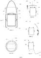
- FIG. 1 illustrates an example of a spacecraft reconfigurable from a launch configuration to an on-orbit configuration in accordance with an implementation.
- a spacecraft 100 is depicted, as configured in a launch configuration, within a launch vehicle fairing 1000.
- the spacecraft 100 may include a main body structure 110 disposed between and defining an aft surface 111 and a forward surface 115.
- the aft surface 111 may be disposed proximate to a structural interface adapter 120.
- the structural interface adapter 120 may be configured to mate with a launch vehicle upper stage (not illustrated).
- a deployable element 130 is disposed, in the launch configuration, forward of forward surface 115.
- the deployable element 130 may be an antenna reflector antenna reflector and include a rigid, curved surface defining a bore sight 131 and an aperture plane 132 substantially orthogonal thereto.
- antenna reflector 130 may be disposed, in the launch configuration, such that its aperture plane 132 is substantially parallel to the forward surface (i.e., orthogonal to the longitudinal axis 1001 of the launch vehicle fairing 1000).
- aperture plane 132 is substantially parallel to the forward surface (i.e., orthogonal to the longitudinal axis 1001 of the launch vehicle fairing 1000).
- a diameter of the reflector 130 may be nearly as large as a diameter of the launch vehicle fairing 1000.
- the deployable element 130 may be mechanically attached with the spacecraft main body 110 by way of one or more structural arrangements 140.
- Each arrangement 140 may include a separable mechanical linkage between the deployable element 130 and the spacecraft main body 110.
- the arrangement 140 may, in the launch configuration, be configured to rigidly couple the deployable element 130 with the spacecraft main body 110, and be configured to withstand dynamic launch loads.
- the arrangement 140 may include a release mechanism (not illustrated). Actuation of the release mechanism may result in detaching the deployable element 130 from the spacecraft main body 110. As a result of being detached the deployable element 130 may be free to be moved into the on-orbit configuration as described below.
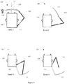
- FIG. B a configuration is illustrated that may occur as part of a transition between the launch configuration illustrated in detail A and the on-orbit configuration illustrated in Detail D.
- the arrangements 140 have been detached and the deployable element 130 has been separated a distance forward of the forward surface 115 of the spacecraft main body 110.
- the deployable element 130 is depicted as being rotated substantially outboard of the spacecraft main body toward a position consistent with a desired on-orbit configuration (Detail D).
- the spacecraft 100 is illustrated in the on-orbit configuration.
- the deployable element 130 is mechanically attached with the spacecraft body 110 by way of second structural arrangement 160 in a position that is substantially outboard of the main body structure.
- the structural arrangement 160 may be a boom or yoke having an articulable connection with the spacecraft main body 110.
- the structural arrangement 160 may include one or more hinged joints and/or actuators.
- the arrangement 160 may be fixedly attached with the spacecraft main body 110.
- the arrangement 160 may include a two or three axis positioning mechanism configured to steer the deployable element 130.
- the transition configuration includes the deployable element 130 being coupled with the spacecraft only by way of a mechanical linkage (not illustrated) between the deployable element 130 and the spacecraft main body 110.
- the mechanical linkage may include a manipulator, for example a ground controlled telerobotic arm or other remote manipulator.
- the remote manipulator may be a self-relocatable manipulator that includes one or more features described in US Patent 4,585,388 and US patent 4,929,009 .
- each reflector 230 may be deployed with a respective mechanism that has one or more degrees of freedom. Each mechanism is ordinarily permanently attached (tethered) at one extremity to the spacecraft and at another extremity to the reflector.
- a spacecraft may be configured with deployable elements that are more numerous and/or larger in size than has been contemplated by the prior art where moving the deployable elements from a stowed location to a deployed location using is accomplished by means other than the arrangements with which the reflector is attached to the spacecraft in the launch configuration and in the on-orbit configuration.
- the deployable elements may be moved from the stowed location to the deployed location by a mechanism which may be or include a multipurpose manipulator configured for grasping and moving any number of deployable elements.
- the presently disclosed techniques permit the arrangements supporting the deployable elements on-orbit to be considerably simplified, and have lower mass and cost than conventional arrangements.
- the reflector when the deployable element 130 is a rigid antenna reflector, the reflector may be arranged in the launch configuration above the spacecraft main body, with the aperture plane parallel to the spacecraft forward surface (i.e., orthogonal to a launch vehicle longitudinal axis). As a result, the diameter of a circular reflector can be nearly as large as the launch vehicle fairing diameter.
- the multipurpose manipulator may include a robotic arm having two end effectors and several articulable joints disposed therebetween.
- Manipulator 350 includes first and second longitudinally elongated arms 356 and 358. Respective proximal ends of the arms 356 and 358 may be coupled together by means an elbow joint 354. Articulator 357 including one or more articulable joints may be coupled with a distal end of arm 356. Similarly, articulator 359 may be coupled with a distal end of arm 358. In some implementations one or both of the articulator 357 and the articulator 359 includes a pitch joint, a yaw joint, and a roll joint. First and second end effectors 351 and 352 may be mounted at the respective distal ends of the articulators 357 and 359.
- FIG. 4 techniques wherein a manipulator 450 is used to move a deployable element 130 from a position associated with the launch configuration to a position associated with the on-orbit configuration will be described.
- Detail E of Figure 4 a configuration is illustrated that may occur as part of a transition between the launch configuration the on-orbit configuration.
- the manipulator 450 may include a proximal portion having a first end effector that is attached to the spacecraft main body 110 at a location 470.
- the location 470 may include a grappling fixture (not illustrated) with which the first end effector of the manipulator 450 is configured to connect.
- a distal portion of the manipulator 450 may include a second end effector that is detachably engaged with the deployable element 130.
- the deployable element 130 is depicted as having been translated and rotated, by the manipulator 450, with respect to the spacecraft main body 110 toward a position consistent with a desired on-orbit configuration (Detail G).
- the manipulator 450 has positioned the deployable element 130 proximate to a desired on-orbit location. More particularly, in the illustrated configuration, the deployable element 130 has been positioned proximate to the second arrangement 160 such that it may be mechanically attached with the spacecraft body 110 by way of the second structural arrangement 160.
- the manipulator 450 may be configured to attach the deployable element 130 to the second arrangement 160. Subsequent to attaching the deployable element 130 to the second arrangement 160, the second end effector of the manipulator 450 may be detached and separated from the deployable element 130 (Detail H).
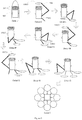
- a launch configuration is illustrated wherein multiple antenna reflectors 530 are disposed forward of a forward surface of the spacecraft main body structure 510.
- the antenna reflectors 530 may be mechanically attached with the spacecraft main body 110 by mechanical structural arrangements (not illustrated). In some implementations, the mechanical structural arrangements may be similar to arrangements 140 described previously in connection with Figure 1 .
- a first antenna reflector 530(1) has been detached and the antenna reflector 530(1) has been moved away from the spacecraft main body 510 by a manipulator 550.
- the manipulator 550 may include a proximal portion having a first end effector that is attached to the spacecraft main body 110 at a location 570(1).
- the location 570(1) may include a first grappling fixture (not illustrated) with which the first end effector of the manipulator 550 is configured to connect.
- a distal portion of the manipulator 550 may include a second end effector that is detachably engaged with the antenna reflector 530(1).
- the antenna reflector 530(1) is depicted as having been translated and rotated, by the manipulator 550, with respect to the spacecraft main body 510, into a position consistent with a desired on-orbit configuration. More particularly, it is illustrated that the manipulator 550 has positioned the deployable element 530(1) proximate to an arrangement 560(1) such that it may be mechanically attached with the spacecraft body 110 by way of the arrangement 560(1).
- the manipulator 450 may be configured to attach the deployable element 530(1) to the arrangement 560(1). Subsequent to attaching the deployable element 530(1) to the arrangement 560(1), the second end effector of the manipulator 550 may be detached and separated from the antenna reflector 530(1).
- the preceding two steps may be repeated with respect to a second antenna reflector 530(2).
- a second antenna reflector 530(2) has been detached and the antenna reflector 530(2) has been moved away from the spacecraft main body 510 by the manipulator 550.
- the antenna reflector 530(3) is depicted as having been translated and rotated, by the manipulator 550, with respect to the spacecraft main body 510, into a position consistent with a desired on-orbit configuration.
- the manipulator 550 has positioned the deployable element 530(2) proximate to an arrangement 560(2) such that it may be mechanically attached with the spacecraft body 110 by way of the arrangement 560(2).
- the manipulator 450 may be configured to attach the deployable element 530(2) to the arrangement 560(2). Subsequent to attaching the deployable element 530(2) to the arrangement 560(2), the second end effector of the manipulator 550 may be detached and separated from the antenna reflector 530(2).
- on-orbit assembly of a plurality of antenna reflectors 530 to the spacecraft main body 510 may include relocating the manipulator 550 with respect to the spacecraft main body 510.
- the second end effector of the manipulator 550 may be engaged, at location 570(2), with a second grappling fixture (not illustrated). Subsequently, the first end effector of the manipulator 550 may be disengaged from the first grappling fixture.
- the first end effector of the manipulator 550 may be detachably engaged with the antenna reflector 530(3) and assembly of the plurality of antenna reflectors 530 to the spacecraft main body 510 may continue as illustrated, for example, in Detail R and Detail S.
- a complex spacecraft including an arrangement of multiple antenna reflectors such as illustrated in Detail T may be assembled on-orbit.
- a stack of eight antenna reflectors 530 is disposed forward of the forward surface of the spacecraft main body structure 510. It should be noted that any number of other launch configuration arrangements are within the contemplation of the present disclosure. For example there may be multiple stacks of deployable elements, disposed forward or aft of the forward surface of the spacecraft main body structure 510. Furthermore, in some implementations one or more reflectors may have an aperture plane orthogonal to the forward surface (i.e., parallel to a longitudinal axis of the launch vehicle).
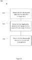
- Figure 6 illustrates a process flow diagram for reconfiguring a spacecraft from a launch configuration to an on-orbit configuration.
- the spacecraft may include a main body structure and at least a first deployable element.
- the first deployable element is mechanically attached with the spacecraft main body structure by way of a first arrangement.
- the first arrangement may be or include a launch holddown device, for example.
- the first deployable element is mechanically attached with the spacecraft main body structure by way of a second arrangement.
- the second arrangement may be or include a hinged joint, an actuator, a two axis positioning mechanism, and a three axis positioning mechanism, for example.
- both the first arrangement and the second arrangement are detached from the first deployable element.
- the method 600 may start, at block 610 with detaching the first deployable element from the first arrangement.
- the first deployable element may be moved with respect to the spacecraft main body structure.
- the first deployable element may be moved using a manipulator.
- the first deployable element may be detached from both the first arrangement and the second arrangement.
- the first deployable element may be moved from a first position proximate to the first arrangement to a second position proximate to the second arrangement.
- the method 600 may finish, at block 630, with attaching the first deployable element to the second arrangement.
Landscapes
- Engineering & Computer Science (AREA)
- Remote Sensing (AREA)
- Aviation & Aerospace Engineering (AREA)
- Aerials With Secondary Devices (AREA)
- Details Of Aerials (AREA)
Claims (15)
- Raumfahrzeug (100), umfassend:eine Hauptkörperstruktur (110);mindestens ein erstes ausschwenkbares Element (130);eine erste mechanische Befestigungsanordnung (140); undeine zweite mechanische Befestigungsvorrichtung (160),wobei das Raumfahrzeug (100) von einer Startkonfiguration in eine Konfiguration im Orbit rekonfigurierbar ist, wobei:das Raumfahrzeug (100) in der Startkonfiguration dazu konfiguriert ist, innerhalb einer Nutzlastverkleidung (1000) angeordnet zu werden, und das erste ausschwenkbare Element (130) mechanisch an der Hauptkörperstruktur (110) des Raumfahrzeugs mittels der ersten mechanischen Befestigungsanordnung (140) befestigt ist;in der Konfiguration im Orbit, das erste ausschwenkbare Element (130) mechanisch an der Hauptkörperstruktur (110) des Raumfahrzeugs mittels der zweiten mechanischen Befestigungsanordnung (160) befestigt ist; undin einer Übergangskonfiguration, die zwischen der Startkonfiguration und der Konfiguration im Orbit liegt, sowohl die erste mechanische Befestigungsanordnung (140) als auch die zweite mechanische Befestigungsanordnung (160) von dem ersten ausschwenkbaren Element (130) abgelöst sind.
- Raumfahrzeug (100) nach Anspruch 1, ferner umfassend:einen strukturellen Schnittstellenadapter (120) zum Anpassen an eine Trägerrakete;eine hintere Fläche (111), die in der Nähe des strukturellen Schnittstellenadapters (120) angeordnet ist;eine vordere Fläche (115), die gegenüber der hinteren Fläche (111) angeordnet ist; unddie Hauptkörperstruktur (110), die zwischen der hinteren Fläche (111) und der vorderen Fläche (115) angeordnet ist; wobei:
in der Startkonfiguration das erste ausschwenkbare Element (130) vor der vorderen Fläche (115) angeordnet ist und in der Konfiguration im Orbit so angeordnet und ausgeschwenkt ist, dass es im Wesentlichen außerhalb der Hauptkörperstruktur (110) liegt. - Raumfahrzeug (100) nach einem der Ansprüche 1 und 2, wobei:das erste ausschwenkbare Element (130) ein Antennenreflektor mit einer Öffnungsebene (132) ist, und,in der Startkonfiguration, der Antennenreflektor mit der Öffnungsebene (132) im Wesentlichen parallel zur vorderen Fläche (115) angeordnet ist.
- Raumfahrzeug (100) nach Anspruch 3, wobei in der Startkonfiguration ein Schwerpunkt der Öffnungsebene (132) im Wesentlichen nach einer Trägerraketen-Längsachse (1001) ausgerichtet ist.
- Raumfahrzeug (100) nach einem der Ansprüche 2 bis 4, wobei die erste mechanische Befestigungsanordnung (140) eine Start-Niederhaltevorrichtung ist und die zweite mechanische Befestigungsanordnung (160) eines oder mehrere von einem Raumfahrzeug-Strukturelement, einem Scharniergelenk, einem Aktor, einem zweiachsigen Positionierungsmechanismus und einem dreiachsigen Positionierungsmechanismus umfasst.
- Raumfahrzeug (100) nach einem der Ansprüche 1 bis 5, wobei in der Übergangskonfiguration das erste ausschwenkbare Element (130) mit dem Raumfahrzeug nur über eine mechanische Verbindung gekoppelt ist, wobei die mechanische Verbindung einen Manipulator (350; 450; 550) umfasst.
- Raumfahrzeug (100) nach Anspruch 6, wobei der Manipulator (350; 450; 550) konfiguriert ist, um:das erste ausschwenkbare Element (130) zu greifen;das erste ausschwenkbare Element (130) von einer ersten Position nahe der ersten mechanischen Befestigungsanordnung (140) in eine zweite Position nahe der zweiten mechanischen Befestigungsanordnung (160) zu bewegen; unddas erste ausschwenkbare Element (130) freizugeben.
- Raumfahrzeug (100) nach Anspruch 7, wobei der Manipulator (350; 450; 550) ferner dazu konfiguriert ist, das ausschwenkbare Element (130) an der zweiten mechanischen Befestigungsanordnung (160) zu befestigen.
- Raumfahrzeug nach einem der Ansprüche 6 bis 8, ferner umfassend mindestens ein zweites ausschwenkbares Element, wobei der Manipulator (350; 450; 550) konfiguriert ist, um:das zweite ausschwenkbare Element zu greifen;das zweite ausschwenkbare Element zu bewegen; unddas zweite ausschwenkbare Element freizugeben.
- Verfahren, umfassend:
Rekonfigurieren eines Raumfahrzeugs (100) von einer Startkonfiguration in eine Konfiguration im Orbit, wobeidas Raumfahrzeug (100) eine Hauptkörperstruktur (110), eine erste mechanische Befestigungsanordnung (140), eine zweite mechanische Befestigungsanordnung (160) und mindestens ein erstes ausschwenkbares Element (130) umfasst;in der Startkonfiguration das Raumfahrzeug (100) dazu konfiguriert ist, innerhalb einer Nutzlastverkleidung (1000) angeordnet zu werden, und das erste ausschwenkbare Element (130) mechanisch an der Hauptkörperstruktur (110) des Raumfahrzeugs mittels der ersten mechanischen Befestigungsanordnung (140) befestigt ist;in der Konfiguration im Orbit, das erste ausschwenkbare Element (130) mechanisch mit der Hauptkörperstruktur (110) des Raumfahrzeugs mittels der zweiten mechanischen Befestigungsanordnung (160) befestigt ist;in einer Übergangskonfiguration, die zwischen der Startkonfiguration und der Konfiguration im Orbit liegt, sowohl die erste mechanische Befestigungsanordnung (140) als auch die zweite mechanische Befestigungsanordnung (160) von dem ersten ausschwenkbaren Element (130) abgelöst sind; undwobei das Rekonfigurieren umfasst:Ablösen des ersten ausschwenkbaren Elements von der ersten mechanischen Befestigungsanordnung (140);Bewegen des ersten ausschwenkbaren Elements (130) in Bezug auf die Hauptkörperstruktur (110) des Raumfahrzeugs; undBefestigen des ersten ausschwenkbaren Elements (130) an der zweiten mechanischen Befestigungsvorrichtung (160). - Verfahren nach Anspruch 10, wobei:das Raumfahrzeug (100) ferner umfasst:einen strukturellen Schnittstellenadapter (120) zum Anpassen an eine Trägerrakete;eine hintere Fläche (111), die in der Nähe des strukturellen Schnittstellenadapters angeordnet ist;eine vordere Fläche (115), die gegenüber der hinteren Fläche (111) angeordnet ist;eine Hauptkörperstruktur (110), die zwischen der hinteren Fläche (111) und der vorderen Fläche (115) angeordnet ist; und,in der Startkonfiguration, das erste ausschwenkbare Element (130) vor der vorderen Fläche (115) angeordnet ist und in der Konfiguration im Orbit so angeordnet und ausgeschwenkt ist, dass es im Wesentlichen außerhalb der Hauptkörperstruktur (110) liegt.
- Verfahren nach einem der Ansprüche 10 und 11, wobei:
das erste ausschwenkbare Element (130) ein Antennenreflektor mit einer Öffnungsebene (132) ist und in der Startkonfiguration der Antennenreflektor so angeordnet ist, dass die Öffnungsebene (132) im Wesentlichen parallel zur vorderen Fläche (115) liegt. - Verfahren nach einem der Ansprüche 10 bis 12, wobei in der Übergangskonfiguration das erste ausschwenkbare Element (130) mit dem Raumfahrzeug (100) nur mittels einer mechanischen Verbindung gekoppelt ist, wobei die mechanische Verbindung einen Manipulator (350; 450; 550) umfasst.
- Verfahren nach Anspruch 13, wobei:das Raumfahrzeug (100) ferner mindestens ein zweites ausschwenkbares Element umfasst; undder Manipulator (350; 450; 550) konfiguriert ist, um:das zweite ausschwenkbare Element zu greifen;das zweite ausschwenkbare Element zu bewegen; unddas zweite ausschwenkbare Element freigeben.
- Verfahren nach einem der Ansprüche 13 oder 14, wobei der Manipulator (350; 450; 550) ein selbstverschiebbarer Roboterarm (356; 358) ist, wobei der Roboterarm mindestens zwei Endeffektoren (351; 352) und eine Vielzahl von gelenkigen Verbindungen aufweist, die zwischen den mindestens zwei Endeffektoren (351; 352) angeordnet sind.
Applications Claiming Priority (2)
| Application Number | Priority Date | Filing Date | Title |
|---|---|---|---|
| US14/642,486 US9878806B2 (en) | 2015-03-09 | 2015-03-09 | On-orbit assembly of communication satellites |
| PCT/US2016/021213 WO2016144884A1 (en) | 2015-03-09 | 2016-03-07 | On-orbit assembly of communication satellites |
Publications (2)
| Publication Number | Publication Date |
|---|---|
| EP3268282A1 EP3268282A1 (de) | 2018-01-17 |
| EP3268282B1 true EP3268282B1 (de) | 2020-02-26 |
Family
ID=55588600
Family Applications (1)
| Application Number | Title | Priority Date | Filing Date |
|---|---|---|---|
| EP16711451.1A Active EP3268282B1 (de) | 2015-03-09 | 2016-03-07 | Umlaufbahnmontage von kommunikationssatelliten |
Country Status (3)
| Country | Link |
|---|---|
| US (2) | US9878806B2 (de) |
| EP (1) | EP3268282B1 (de) |
| WO (1) | WO2016144884A1 (de) |
Families Citing this family (24)
| Publication number | Priority date | Publication date | Assignee | Title |
|---|---|---|---|---|
| US9878806B2 (en) | 2015-03-09 | 2018-01-30 | Space Systems/Loral, Llc | On-orbit assembly of communication satellites |
| US9970517B2 (en) * | 2015-07-28 | 2018-05-15 | Northrop Grumman Systems Corporation | Satellite boom hinge actuator using drive chain with flexible and rigid characteristics |
| US10569911B2 (en) * | 2015-09-13 | 2020-02-25 | Nanoracks, Llc | Spacecraft systems and methods |
| US10850872B2 (en) * | 2015-09-13 | 2020-12-01 | NanoRocks, LLC | Spacecraft systems airlock for international space station access and interface and methods of operation |
| US10053240B1 (en) * | 2016-05-20 | 2018-08-21 | Space Systems/Loral, Llc | Stowage, deployment and positioning of rigid antenna reflectors on a spacecraft |
| US10730643B1 (en) | 2016-09-08 | 2020-08-04 | Space Systems/Loral, Llc | Space based robotic assembly of a modular reflector |
| US10661918B2 (en) | 2016-10-04 | 2020-05-26 | Space Systems/Loral, Llc | Self-assembling persistent space platform |
| US11286062B1 (en) | 2016-10-27 | 2022-03-29 | Space Systems/Loral, Llc | Spacecraft exoskeleton truss structure |
| US11254453B2 (en) | 2016-11-14 | 2022-02-22 | Space Systems/Loral, Llc | Smallsat payload configuration |
| US10538347B1 (en) * | 2016-11-14 | 2020-01-21 | Space Systems/Loral, Llc | Smallsat payload configuration |
| US10633123B2 (en) * | 2017-04-05 | 2020-04-28 | Space Systems/Loral, Llc | Exoskeletal launch support structure |
| US10800551B2 (en) | 2017-06-21 | 2020-10-13 | Space Systems/Loral, Llc | High capacity communication satellite |
| WO2019018821A1 (en) | 2017-07-21 | 2019-01-24 | Northrop Grumman Innovation Systems, Inc. | MAINTENANCE DEVICES FOR SPACE MACHINES AND ASSOCIATED ASSEMBLIES, SYSTEMS AND METHODS |
| US10957986B2 (en) | 2017-08-04 | 2021-03-23 | Space Systems/Loral, Llc | Reconfigurable spacecraft with a hold-down assembly for a rigid reflector |
| FR3086927B1 (fr) * | 2018-10-04 | 2020-09-18 | Thales Sa | Dispositif de deploiement |
| EP3911574A4 (de) | 2019-01-15 | 2022-09-14 | Northrop Grumman Systems Corporation | Wartungsvorrichtungen für raumfahrzeuge und zugehörige anordnungen, systeme und verfahren |
| CN110844121B (zh) * | 2019-10-22 | 2022-07-12 | 西北工业大学深圳研究院 | 一种在轨装配航天器协同运输的合作博弈控制方法 |
| EP3851386B1 (de) * | 2020-01-15 | 2023-03-08 | Airbus Defence and Space Limited | Montagevorrichtung |
| US11827386B2 (en) | 2020-05-04 | 2023-11-28 | Northrop Grumman Systems Corporation | Vehicle capture assemblies and related devices, systems, and methods |
| US12371195B2 (en) | 2020-05-04 | 2025-07-29 | Northrop Grumman Systems Corporation | Vehicle capture assemblies and related devices, systems, and methods |
| CN112404984B (zh) * | 2020-12-01 | 2022-04-12 | 哈尔滨工业大学 | 基于多空间机器人的超大型空间望远镜在轨组装系统 |
| CN113581502B (zh) * | 2021-08-11 | 2023-05-26 | 哈尔滨工业大学 | 基于多空间机器人系统的超大型太空望远镜在轨组装方法 |
| CN114839870B (zh) * | 2022-04-13 | 2025-04-18 | 西北工业大学深圳研究院 | 一种面向大型航天器在轨装配的多目标优化控制方法 |
| US12338006B2 (en) | 2022-11-18 | 2025-06-24 | Northrop Grumman Systems Corporation | Movable platforms for vehicle capture assemblies and related devices, assemblies, systems, and methods |
Family Cites Families (21)
| Publication number | Priority date | Publication date | Assignee | Title |
|---|---|---|---|---|
| US3893573A (en) * | 1973-08-20 | 1975-07-08 | Nasa | Variable ratio mixed-mode bilateral master-slave control system for shuttle remote manipulator system |
| CA1049065A (en) * | 1976-01-30 | 1979-02-20 | Ernest Groskopfs | Module exchanger systems |
| US4585388A (en) | 1984-05-08 | 1986-04-29 | Spar Aerospace Limited | Self-relocating manipulator |
| US4667908A (en) * | 1984-11-20 | 1987-05-26 | Rca Corporation | Multiple body handling operations on the space shuttle |
| US4834325A (en) * | 1985-03-20 | 1989-05-30 | Space Industries, Inc. | Modular spacecraft system |
| CA1294997C (en) | 1987-09-28 | 1992-01-28 | Ron Vandersluis | End effectors and grapple fixtures |
| US4926181A (en) | 1988-08-26 | 1990-05-15 | Stumm James E | Deployable membrane shell reflector |
| US5145130A (en) * | 1991-10-23 | 1992-09-08 | The United States Of America As Represented By The Administrator Of The National Aeronautics & Space Administration | Robot serviced space facility |
| EP0541052B1 (de) * | 1991-11-05 | 1996-02-07 | Hitachi, Ltd. | System von Raumfahrzeugen |
| US5996940A (en) * | 1997-07-07 | 1999-12-07 | Hughes Electronics Corporation | Apparatus and method for combined redundant deployment and launch locking of deployable satellite appendages |
| ATE348413T1 (de) * | 2002-12-30 | 2007-01-15 | Ems Technologies Canada Ltd | Verfahren zur verbesserung der entkopplung von einer auf einer struktur montierten antenne |
| US7114682B1 (en) | 2004-02-18 | 2006-10-03 | Kistler Walter P | System and method for transportation and storage of cargo in space |
| ES2539205T3 (es) * | 2004-04-08 | 2015-06-26 | Astrium Limited | Mástil desplegable |
| US7138960B2 (en) | 2004-08-27 | 2006-11-21 | United Technologies Corporation | Deployable electromagnetic concentrator |
| US7714797B2 (en) | 2005-03-04 | 2010-05-11 | Astrium Limited | Phased array antenna |
| US7602349B2 (en) | 2006-02-24 | 2009-10-13 | Lockheed Martin Corporation | System of stowing and deploying multiple phased arrays or combinations of arrays and reflectors |
| FR2937800B1 (fr) | 2008-10-24 | 2010-11-12 | Thales Sa | Antenne a longue focale, compacte, robuste et testable au sol, montee sur satellite |
| US8789796B2 (en) | 2010-09-16 | 2014-07-29 | Space Systems/Loral, Llc | High capacity broadband satellite |
| US8448902B2 (en) | 2011-02-11 | 2013-05-28 | Space Systems/Loral LLC | Satellite having multiple aspect ratios |
| US9004409B1 (en) | 2011-08-23 | 2015-04-14 | Space Systems/Loral, Llc | Extendable antenna reflector deployment techniques |
| US9878806B2 (en) | 2015-03-09 | 2018-01-30 | Space Systems/Loral, Llc | On-orbit assembly of communication satellites |
-
2015
- 2015-03-09 US US14/642,486 patent/US9878806B2/en active Active
-
2016
- 2016-03-07 WO PCT/US2016/021213 patent/WO2016144884A1/en not_active Ceased
- 2016-03-07 EP EP16711451.1A patent/EP3268282B1/de active Active
-
2017
- 2017-12-19 US US15/847,780 patent/US10518909B2/en active Active
Non-Patent Citations (1)
| Title |
|---|
| None * |
Also Published As
| Publication number | Publication date |
|---|---|
| EP3268282A1 (de) | 2018-01-17 |
| WO2016144884A1 (en) | 2016-09-15 |
| US9878806B2 (en) | 2018-01-30 |
| US10518909B2 (en) | 2019-12-31 |
| US20160264264A1 (en) | 2016-09-15 |
| US20180111704A1 (en) | 2018-04-26 |
Similar Documents
| Publication | Publication Date | Title |
|---|---|---|
| EP3268282B1 (de) | Umlaufbahnmontage von kommunikationssatelliten | |
| EP3305666B1 (de) | Raumfahrzeug, verfahren und system | |
| EP4015398B1 (de) | Gestapelte satellitenanordnungen und zugehörige verfahren | |
| AU2018304706B2 (en) | Spacecraft servicing devices and related assemblies, systems, and methods | |
| EP3782914B1 (de) | Satellitenausgeber und verfahren zur unterstützung einer vielzahl von satelliten | |
| US8006938B2 (en) | Spacecraft servicing vehicle with adaptors, tools and attachment mechanisms | |
| US10730643B1 (en) | Space based robotic assembly of a modular reflector | |
| CN113608346B (zh) | 超大型太空望远镜模块化子镜拼接方案及标准化接口 | |
| US10435183B1 (en) | Deployable propulsion module for spacecraft | |
| US10538347B1 (en) | Smallsat payload configuration | |
| US10053240B1 (en) | Stowage, deployment and positioning of rigid antenna reflectors on a spacecraft | |
| CN105246782A (zh) | 航天飞机轨道飞行器和返回系统 | |
| WO2019108272A1 (en) | Flexible satellite for deployment from attachment hub | |
| US4657211A (en) | Spacecraft to shuttle docking method and apparatus | |
| US10214303B1 (en) | Low cost launch vehicle fairing | |
| US4667908A (en) | Multiple body handling operations on the space shuttle | |
| EP3438003B1 (de) | Multireflektorniederhalteanordnung |
Legal Events
| Date | Code | Title | Description |
|---|---|---|---|
| STAA | Information on the status of an ep patent application or granted ep patent |
Free format text: STATUS: THE INTERNATIONAL PUBLICATION HAS BEEN MADE |
|
| PUAI | Public reference made under article 153(3) epc to a published international application that has entered the european phase |
Free format text: ORIGINAL CODE: 0009012 |
|
| STAA | Information on the status of an ep patent application or granted ep patent |
Free format text: STATUS: REQUEST FOR EXAMINATION WAS MADE |
|
| 17P | Request for examination filed |
Effective date: 20170814 |
|
| AK | Designated contracting states |
Kind code of ref document: A1 Designated state(s): AL AT BE BG CH CY CZ DE DK EE ES FI FR GB GR HR HU IE IS IT LI LT LU LV MC MK MT NL NO PL PT RO RS SE SI SK SM TR |
|
| AX | Request for extension of the european patent |
Extension state: BA ME |
|
| RIN1 | Information on inventor provided before grant (corrected) |
Inventor name: HELMER, ROBERT, EDWARD Inventor name: LYMER, JOHN, DOUGLAS |
|
| DAV | Request for validation of the european patent (deleted) | ||
| DAX | Request for extension of the european patent (deleted) | ||
| GRAP | Despatch of communication of intention to grant a patent |
Free format text: ORIGINAL CODE: EPIDOSNIGR1 |
|
| STAA | Information on the status of an ep patent application or granted ep patent |
Free format text: STATUS: GRANT OF PATENT IS INTENDED |
|
| INTG | Intention to grant announced |
Effective date: 20191120 |
|
| RIN1 | Information on inventor provided before grant (corrected) |
Inventor name: HELMER, ROBERT EDWARD Inventor name: LYMER, JOHN DOUGLAS |
|
| GRAS | Grant fee paid |
Free format text: ORIGINAL CODE: EPIDOSNIGR3 |
|
| GRAA | (expected) grant |
Free format text: ORIGINAL CODE: 0009210 |
|
| STAA | Information on the status of an ep patent application or granted ep patent |
Free format text: STATUS: THE PATENT HAS BEEN GRANTED |
|
| AK | Designated contracting states |
Kind code of ref document: B1 Designated state(s): AL AT BE BG CH CY CZ DE DK EE ES FI FR GB GR HR HU IE IS IT LI LT LU LV MC MK MT NL NO PL PT RO RS SE SI SK SM TR |
|
| REG | Reference to a national code |
Ref country code: GB Ref legal event code: FG4D |
|
| REG | Reference to a national code |
Ref country code: CH Ref legal event code: EP |
|
| REG | Reference to a national code |
Ref country code: AT Ref legal event code: REF Ref document number: 1237352 Country of ref document: AT Kind code of ref document: T Effective date: 20200315 |
|
| REG | Reference to a national code |
Ref country code: IE Ref legal event code: FG4D |
|
| REG | Reference to a national code |
Ref country code: DE Ref legal event code: R096 Ref document number: 602016030513 Country of ref document: DE |
|
| PG25 | Lapsed in a contracting state [announced via postgrant information from national office to epo] |
Ref country code: NO Free format text: LAPSE BECAUSE OF FAILURE TO SUBMIT A TRANSLATION OF THE DESCRIPTION OR TO PAY THE FEE WITHIN THE PRESCRIBED TIME-LIMIT Effective date: 20200526 Ref country code: FI Free format text: LAPSE BECAUSE OF FAILURE TO SUBMIT A TRANSLATION OF THE DESCRIPTION OR TO PAY THE FEE WITHIN THE PRESCRIBED TIME-LIMIT Effective date: 20200226 Ref country code: RS Free format text: LAPSE BECAUSE OF FAILURE TO SUBMIT A TRANSLATION OF THE DESCRIPTION OR TO PAY THE FEE WITHIN THE PRESCRIBED TIME-LIMIT Effective date: 20200226 |
|
| REG | Reference to a national code |
Ref country code: NL Ref legal event code: MP Effective date: 20200226 |
|
| REG | Reference to a national code |
Ref country code: LT Ref legal event code: MG4D |
|
| PG25 | Lapsed in a contracting state [announced via postgrant information from national office to epo] |
Ref country code: GR Free format text: LAPSE BECAUSE OF FAILURE TO SUBMIT A TRANSLATION OF THE DESCRIPTION OR TO PAY THE FEE WITHIN THE PRESCRIBED TIME-LIMIT Effective date: 20200527 Ref country code: IS Free format text: LAPSE BECAUSE OF FAILURE TO SUBMIT A TRANSLATION OF THE DESCRIPTION OR TO PAY THE FEE WITHIN THE PRESCRIBED TIME-LIMIT Effective date: 20200626 Ref country code: BG Free format text: LAPSE BECAUSE OF FAILURE TO SUBMIT A TRANSLATION OF THE DESCRIPTION OR TO PAY THE FEE WITHIN THE PRESCRIBED TIME-LIMIT Effective date: 20200526 Ref country code: SE Free format text: LAPSE BECAUSE OF FAILURE TO SUBMIT A TRANSLATION OF THE DESCRIPTION OR TO PAY THE FEE WITHIN THE PRESCRIBED TIME-LIMIT Effective date: 20200226 Ref country code: LV Free format text: LAPSE BECAUSE OF FAILURE TO SUBMIT A TRANSLATION OF THE DESCRIPTION OR TO PAY THE FEE WITHIN THE PRESCRIBED TIME-LIMIT Effective date: 20200226 Ref country code: HR Free format text: LAPSE BECAUSE OF FAILURE TO SUBMIT A TRANSLATION OF THE DESCRIPTION OR TO PAY THE FEE WITHIN THE PRESCRIBED TIME-LIMIT Effective date: 20200226 |
|
| PG25 | Lapsed in a contracting state [announced via postgrant information from national office to epo] |
Ref country code: NL Free format text: LAPSE BECAUSE OF FAILURE TO SUBMIT A TRANSLATION OF THE DESCRIPTION OR TO PAY THE FEE WITHIN THE PRESCRIBED TIME-LIMIT Effective date: 20200226 |
|
| REG | Reference to a national code |
Ref country code: DE Ref legal event code: R119 Ref document number: 602016030513 Country of ref document: DE |
|
| PG25 | Lapsed in a contracting state [announced via postgrant information from national office to epo] |
Ref country code: ES Free format text: LAPSE BECAUSE OF FAILURE TO SUBMIT A TRANSLATION OF THE DESCRIPTION OR TO PAY THE FEE WITHIN THE PRESCRIBED TIME-LIMIT Effective date: 20200226 Ref country code: PT Free format text: LAPSE BECAUSE OF FAILURE TO SUBMIT A TRANSLATION OF THE DESCRIPTION OR TO PAY THE FEE WITHIN THE PRESCRIBED TIME-LIMIT Effective date: 20200719 Ref country code: DK Free format text: LAPSE BECAUSE OF FAILURE TO SUBMIT A TRANSLATION OF THE DESCRIPTION OR TO PAY THE FEE WITHIN THE PRESCRIBED TIME-LIMIT Effective date: 20200226 Ref country code: SK Free format text: LAPSE BECAUSE OF FAILURE TO SUBMIT A TRANSLATION OF THE DESCRIPTION OR TO PAY THE FEE WITHIN THE PRESCRIBED TIME-LIMIT Effective date: 20200226 Ref country code: SM Free format text: LAPSE BECAUSE OF FAILURE TO SUBMIT A TRANSLATION OF THE DESCRIPTION OR TO PAY THE FEE WITHIN THE PRESCRIBED TIME-LIMIT Effective date: 20200226 Ref country code: CZ Free format text: LAPSE BECAUSE OF FAILURE TO SUBMIT A TRANSLATION OF THE DESCRIPTION OR TO PAY THE FEE WITHIN THE PRESCRIBED TIME-LIMIT Effective date: 20200226 Ref country code: EE Free format text: LAPSE BECAUSE OF FAILURE TO SUBMIT A TRANSLATION OF THE DESCRIPTION OR TO PAY THE FEE WITHIN THE PRESCRIBED TIME-LIMIT Effective date: 20200226 Ref country code: LT Free format text: LAPSE BECAUSE OF FAILURE TO SUBMIT A TRANSLATION OF THE DESCRIPTION OR TO PAY THE FEE WITHIN THE PRESCRIBED TIME-LIMIT Effective date: 20200226 Ref country code: RO Free format text: LAPSE BECAUSE OF FAILURE TO SUBMIT A TRANSLATION OF THE DESCRIPTION OR TO PAY THE FEE WITHIN THE PRESCRIBED TIME-LIMIT Effective date: 20200226 |
|
| REG | Reference to a national code |
Ref country code: CH Ref legal event code: PL |
|
| REG | Reference to a national code |
Ref country code: AT Ref legal event code: MK05 Ref document number: 1237352 Country of ref document: AT Kind code of ref document: T Effective date: 20200226 |
|
| PG25 | Lapsed in a contracting state [announced via postgrant information from national office to epo] |
Ref country code: MC Free format text: LAPSE BECAUSE OF FAILURE TO SUBMIT A TRANSLATION OF THE DESCRIPTION OR TO PAY THE FEE WITHIN THE PRESCRIBED TIME-LIMIT Effective date: 20200226 |
|
| REG | Reference to a national code |
Ref country code: BE Ref legal event code: MM Effective date: 20200331 |
|
| PG25 | Lapsed in a contracting state [announced via postgrant information from national office to epo] |
Ref country code: LU Free format text: LAPSE BECAUSE OF NON-PAYMENT OF DUE FEES Effective date: 20200307 |
|
| PLBE | No opposition filed within time limit |
Free format text: ORIGINAL CODE: 0009261 |
|
| STAA | Information on the status of an ep patent application or granted ep patent |
Free format text: STATUS: NO OPPOSITION FILED WITHIN TIME LIMIT |
|
| PG25 | Lapsed in a contracting state [announced via postgrant information from national office to epo] |
Ref country code: IT Free format text: LAPSE BECAUSE OF FAILURE TO SUBMIT A TRANSLATION OF THE DESCRIPTION OR TO PAY THE FEE WITHIN THE PRESCRIBED TIME-LIMIT Effective date: 20200226 Ref country code: AT Free format text: LAPSE BECAUSE OF FAILURE TO SUBMIT A TRANSLATION OF THE DESCRIPTION OR TO PAY THE FEE WITHIN THE PRESCRIBED TIME-LIMIT Effective date: 20200226 Ref country code: LI Free format text: LAPSE BECAUSE OF NON-PAYMENT OF DUE FEES Effective date: 20200331 Ref country code: IE Free format text: LAPSE BECAUSE OF NON-PAYMENT OF DUE FEES Effective date: 20200307 Ref country code: CH Free format text: LAPSE BECAUSE OF NON-PAYMENT OF DUE FEES Effective date: 20200331 Ref country code: DE Free format text: LAPSE BECAUSE OF NON-PAYMENT OF DUE FEES Effective date: 20201001 |
|
| 26N | No opposition filed |
Effective date: 20201127 |
|
| PG25 | Lapsed in a contracting state [announced via postgrant information from national office to epo] |
Ref country code: PL Free format text: LAPSE BECAUSE OF FAILURE TO SUBMIT A TRANSLATION OF THE DESCRIPTION OR TO PAY THE FEE WITHIN THE PRESCRIBED TIME-LIMIT Effective date: 20200226 Ref country code: SI Free format text: LAPSE BECAUSE OF FAILURE TO SUBMIT A TRANSLATION OF THE DESCRIPTION OR TO PAY THE FEE WITHIN THE PRESCRIBED TIME-LIMIT Effective date: 20200226 Ref country code: BE Free format text: LAPSE BECAUSE OF NON-PAYMENT OF DUE FEES Effective date: 20200331 |
|
| GBPC | Gb: european patent ceased through non-payment of renewal fee |
Effective date: 20200526 |
|
| PG25 | Lapsed in a contracting state [announced via postgrant information from national office to epo] |
Ref country code: GB Free format text: LAPSE BECAUSE OF NON-PAYMENT OF DUE FEES Effective date: 20200526 |
|
| PG25 | Lapsed in a contracting state [announced via postgrant information from national office to epo] |
Ref country code: TR Free format text: LAPSE BECAUSE OF FAILURE TO SUBMIT A TRANSLATION OF THE DESCRIPTION OR TO PAY THE FEE WITHIN THE PRESCRIBED TIME-LIMIT Effective date: 20200226 Ref country code: MT Free format text: LAPSE BECAUSE OF FAILURE TO SUBMIT A TRANSLATION OF THE DESCRIPTION OR TO PAY THE FEE WITHIN THE PRESCRIBED TIME-LIMIT Effective date: 20200226 Ref country code: CY Free format text: LAPSE BECAUSE OF FAILURE TO SUBMIT A TRANSLATION OF THE DESCRIPTION OR TO PAY THE FEE WITHIN THE PRESCRIBED TIME-LIMIT Effective date: 20200226 |
|
| PG25 | Lapsed in a contracting state [announced via postgrant information from national office to epo] |
Ref country code: MK Free format text: LAPSE BECAUSE OF FAILURE TO SUBMIT A TRANSLATION OF THE DESCRIPTION OR TO PAY THE FEE WITHIN THE PRESCRIBED TIME-LIMIT Effective date: 20200226 Ref country code: AL Free format text: LAPSE BECAUSE OF FAILURE TO SUBMIT A TRANSLATION OF THE DESCRIPTION OR TO PAY THE FEE WITHIN THE PRESCRIBED TIME-LIMIT Effective date: 20200226 |
|
| P01 | Opt-out of the competence of the unified patent court (upc) registered |
Effective date: 20230528 |
|
| PGFP | Annual fee paid to national office [announced via postgrant information from national office to epo] |
Ref country code: FR Payment date: 20251231 Year of fee payment: 11 |