EP4015244B1 - Reifen - Google Patents
Reifen Download PDFInfo
- Publication number
- EP4015244B1 EP4015244B1 EP21203439.1A EP21203439A EP4015244B1 EP 4015244 B1 EP4015244 B1 EP 4015244B1 EP 21203439 A EP21203439 A EP 21203439A EP 4015244 B1 EP4015244 B1 EP 4015244B1
- Authority
- EP
- European Patent Office
- Prior art keywords
- groove
- tire
- ground contact
- virtual
- axial position
- Prior art date
- Legal status (The legal status is an assumption and is not a legal conclusion. Google has not performed a legal analysis and makes no representation as to the accuracy of the status listed.)
- Active
Links
Images


Classifications
-
- B—PERFORMING OPERATIONS; TRANSPORTING
- B60—VEHICLES IN GENERAL
- B60C—VEHICLE TYRES; TYRE INFLATION; TYRE CHANGING; CONNECTING VALVES TO INFLATABLE ELASTIC BODIES IN GENERAL; DEVICES OR ARRANGEMENTS RELATED TO TYRES
- B60C11/00—Tyre tread bands; Tread patterns; Anti-skid inserts
- B60C11/03—Tread patterns
- B60C11/0327—Tread patterns characterised by special properties of the tread pattern
- B60C11/0332—Tread patterns characterised by special properties of the tread pattern by the footprint-ground contacting area of the tyre tread
-
- B—PERFORMING OPERATIONS; TRANSPORTING
- B60—VEHICLES IN GENERAL
- B60C—VEHICLE TYRES; TYRE INFLATION; TYRE CHANGING; CONNECTING VALVES TO INFLATABLE ELASTIC BODIES IN GENERAL; DEVICES OR ARRANGEMENTS RELATED TO TYRES
- B60C11/00—Tyre tread bands; Tread patterns; Anti-skid inserts
- B60C11/03—Tread patterns
-
- B—PERFORMING OPERATIONS; TRANSPORTING
- B60—VEHICLES IN GENERAL
- B60C—VEHICLE TYRES; TYRE INFLATION; TYRE CHANGING; CONNECTING VALVES TO INFLATABLE ELASTIC BODIES IN GENERAL; DEVICES OR ARRANGEMENTS RELATED TO TYRES
- B60C11/00—Tyre tread bands; Tread patterns; Anti-skid inserts
- B60C11/0083—Tyre tread bands; Tread patterns; Anti-skid inserts characterised by the curvature of the tyre tread
-
- B—PERFORMING OPERATIONS; TRANSPORTING
- B60—VEHICLES IN GENERAL
- B60C—VEHICLE TYRES; TYRE INFLATION; TYRE CHANGING; CONNECTING VALVES TO INFLATABLE ELASTIC BODIES IN GENERAL; DEVICES OR ARRANGEMENTS RELATED TO TYRES
- B60C11/00—Tyre tread bands; Tread patterns; Anti-skid inserts
- B60C11/03—Tread patterns
- B60C2011/0337—Tread patterns characterised by particular design features of the pattern
- B60C2011/0339—Grooves
- B60C2011/0341—Circumferential grooves
- B60C2011/0353—Circumferential grooves characterised by width
-
- B—PERFORMING OPERATIONS; TRANSPORTING
- B60—VEHICLES IN GENERAL
- B60C—VEHICLE TYRES; TYRE INFLATION; TYRE CHANGING; CONNECTING VALVES TO INFLATABLE ELASTIC BODIES IN GENERAL; DEVICES OR ARRANGEMENTS RELATED TO TYRES
- B60C11/00—Tyre tread bands; Tread patterns; Anti-skid inserts
- B60C11/03—Tread patterns
- B60C2011/0337—Tread patterns characterised by particular design features of the pattern
- B60C2011/0339—Grooves
- B60C2011/0341—Circumferential grooves
- B60C2011/0355—Circumferential grooves characterised by depth
Definitions
- the present invention relates to a tire having a tread portion.
- Patent Document 1 discloses a tire improved in wear resistance by specifically defining the profile of a tread portion in which a plurality of main grooves extending in the tire circumferential direction are formed.
- Patent Document 1 Japanese Patent Application Publication No. 2019-182339
- a tire in accordance with the preamble of claim 1 is known from US 6 443 199 B1 and JP 2009 078790 A .
- Related tires are known from EP 3 173 254 A1 , EP 2 527 163 A1 and EP 3 689 642 A1 .
- a main object of the present invention is to provide a tire in which steering stability performance can be improved, while maintaining excellent wear resistance performance.
- the tire has a large ground contact area and can improve cornering power, therefore, it is possible to improve steering stability performance.
- the groove depth d of each grooves is determined so as to satisfy the above equation (1), the groove depth can be prevented from becoming excessively large for the amount of wear which is different depending on the axial position. As a result, the rigidity of the tread portion is improved, and the cornering power can be improved. Therefore, the tire of the present invention can be improved in steering stability performance while maintaining excellent wear resistance performance.
- the present invention can be applied to various tires such as a pneumatic tire for passenger cars, a pneumatic tire for heavy load vehicles, a pneumatic tire for two-wheeled vehicles, a non-pneumatic tire so called airless tire and the like.
- the present invention is suitably applied to a pneumatic tire for passenger cars.
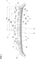
- FIG. 1 is a tire meridian cross-sectional view of a tread portion 2 of a tire 1 as an embodiment under its normal state.
- the "normal state” is a state of the tire 1 which is mounted on a normal rim and inflated to a normal internal pressure but load with no tire load.
- the "normal rim” is a wheel rim specified for the tire by a standard included in a standardization system on which the tire is based, for example, the "normal wheel rim” in JATMA, "Design Rim” in TRA, and “Measuring Rim” in ETRTO. If there is no standardization system including standards on which the tire 1 is to be based, the "normal rim” is a wheel rim specified by the tire manufacturer or the like.
- the "normal inner pressure” is air pressure specified for the tire by a standard included in a standardization system on which the tire is based, for example, the “maximum air pressure” in JATMA, maximum value listed in the "TIRE LOAD LIMITS AT VARIOUS COLD INFLATION PRESSURES" table in TRA, and "INFLATION PRESSURE” in ETRTO. If there is no standardization system including standards on which the tire 1 is to be based, the "normal inner pressure” is air pressure specified by the tire manufacturer or the like.
- the tire 1 of the present embodiment has a tread portion 2 contacting with the ground during running.
- the tread portion 2 in the present embodiment is provided with grooves 3.
- the grooves 3 include a plurality of circumferential grooves 4, in this example, four circumferential grooves 4, each extending in the tire circumferential direction, and a plurality of lateral grooves 5 extending in the tire axial direction.
- the circumferential grooves 4 in this example include a shoulder circumferential groove 4B, and a crown circumferential groove 4A disposed on the tire equator C side of the shoulder circumferential groove 4B.
- the tire 1 has good drainage property when running on wet road surfaces due to such grooves 3.
- FIG. 2 is a schematic view showing a ground contact area 2a of the tread portion 2.
- the ground contact area 2a has ground contact lengths L in the tire circumferential direction associated with respective positions P in the tire axial direction.
- the ground contact area 2a of the present embodiment has a half tread width Tw which is a distance from the tire equator C to a tread edge Te which is an outermost end of the ground contact area 2a in the tire axial direction.
- the tire equator C is the center position in the tire axial direction between the tread edges Te on both sides.
- the "normal load” is a load specified for the tire by a standard included in a standardization system on which the tire is based, for example, the “maximum load capacity” in JATMA, maximum value listed in “TIRE LOAD LIMITS AT VARIOUS COLD INFLATION PRESSURES" table in TRA, and "LOAD CAPACITY” in ETRTO. If there is no standardization system including standards on which the tire 1 is to be based, the "normal load” is a load specified by the tire manufacturer or the like.
- the ground contact lengths L include a crown ground contact length LC at the tire equator C, and a shoulder ground contact length LS at an axial position P1 spaced apart from the tire equator C by a distance w1 of 80% of the half tread width Tw.
- the crown ground contact length LC is in a range from 0.95 to 1.05 times the shoulder ground contact length LS.
- the groove depth d can be prevented from becoming excessively large for the amount of wear which is different depending on the axial positions, and the rigidity of the tread portion 2 is improved to improve the cornering power. Therefore, the tire 1 of the present embodiment can be improved in steering stability performance while maintaining the excellent wear resistance performance.
- the groove depth d0 of the reference virtual groove G0 is determined based on the groove depth d of the actual circumferential groove 4 disposed adjacently to the tire equator C. For example, by determining a curve line which extends with the same radius of curvature R as the radially outer surface 2b of the tread portion at the tire equator C while contacting with the groove bottoms of the crown circumferential grooves 4A disposed on both sides of the tire equator C adjacently thereto, the groove depth d0 of the reference virtual groove G0 is defined as the radial distance between the curve line and the radially outer surface 2b at the tire equator C.
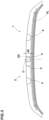
- FIG. 3 shows a meridian cross section of the tread portion 2 of the tire 1 as another embodiment under the normal state.
- the tread portion 2 of the present embodiment is provided with three circumferential grooves 4.
- One of the three circumferential grooves 4 is disposed on the tire equator C.
- the groove depth d0 of the reference virtual groove G0 of the present embodiment is defined as the groove depth d of the circumferential groove 4 arranged on the tire equator C.
- the number of the circumferential grooves 4 may be, for example, two or five or more.
- the groove depths d of the circumferential grooves 4 are preferably defined based on a virtual line VL defined in the tire meridian cross section under the normal state with no tire load as shown in FIGS. 1 and 2 .
- the virtual line VL of the present embodiment is defined based on the reference virtual groove G0, a first virtual groove G1, a second virtual groove G2, and a third virtual groove G3 defined in the tread portion 2 in the tire meridian cross section under the normal state with no tire load.
- the reference virtual groove G0 is a virtual circumferential groove defined at the tire equator C.
- the first virtual groove G1 is a virtual circumferential groove defined at a first axial position P1 spaced apart from the tire equator C in the tire axial direction.
- the second virtual groove G2 is a virtual circumferential groove defined at a second axial position P2 axially outside the first axial position P1.
- the third virtual groove G3 is a virtual circumferential groove defined at a third axial position P3 axially outside the second axial position P2.
- Such virtual line VL can optimize the groove depth d of each circumferential groove 4 for the amount of wear, and can improve the rigidity of the tread portion 2, thereby, it is possible to improve the steering stability performance of the tire 1.
- the virtual line VL helps to reduce the thickness t of the tread rubber 2g of the tread portion 2 to reduce the weight of the tire 1, thereby, it is possible to improve the low-fuel consumption performance of the tire 1.
- the thickness t of the tread rubber 2g is the distance between the radially outer surface 2b of the tread portion 2 and a tread reinforcing layer (belt) B disposed in the tread portion 2.
- the ground contact lengths L include a first ground contact length L1 at the first axial position P1, a second ground contact length L2 at the second axial position P2, and a third ground contact length L3 at the third axial position P3.
- Such first ground contact length L1, second ground contact length L2, and third ground contact length L3 are useful for accurately defining the virtual line VL.
- the correction coefficient ⁇ is preferably a positive number of 2.0 or less.
- the correction coefficient ⁇ is 2.0 or less, it is possible to suppress excessive correction caused by the differences of the first ground contact length L1, the second ground contact length L2, and the third ground contact length L3 from the crown ground contact length LC.
- correction coefficient ⁇ is a positive number, it is possible to reliably correct based on the differences of the first ground contact length L1, the second ground contact length L2, and the third ground contact length L3 from the crown ground contact length LC.
- the correction coefficient ⁇ is 0.8 to 1.2.
- the virtual line VL of the present invention is defined so as to contact with the groove bottom of the reference virtual groove G0, the groove bottom of the first virtual groove G1, the groove bottom of the second virtual groove G2, and the groove bottom of the third virtual groove G3.
- each circumferential groove 4 of the present invention is in a range from 90% to 110% of the distance Ld from the radially outer surface 2b of the tread portion 2 to the virtual line VL measured at the axial position P at which the circumferential groove 4 is formed.
- Such circumferential groove 4 is prevented from having an excessively large groove depth d for the amount of wear which is different depending on the positions P in the tire axial direction, and thereby the rigidity of the tread portion 2 is improved. Therefore, the tire 1 of the present invention can be improved in steering stability performance while maintaining the excellent wear resistance performance.
- the first axial position P1 is spaced apart from the tire equator C at an axial distance W1 of from 40% to 55% of the half tread width Tw.
- the first axial position P1 in this example is located in a middle land portion 6 defined between the crown circumferential groove 4A and the shoulder circumferential groove 4B.
- the second axial position P2 is spaced apart from the tire equator C by an axial distance W2 of from 75% to 80% of the half tread width Tw.
- the second axial position P2 in this example is located in a shoulder land portion 7 defined as extending axially outwardly from the shoulder circumferential groove 4B.
- the second ground contact length L2 is equal to the shoulder ground contact length LS.
- the third axial position P3 is spaced apart from the tire equator C by a distance W3 of from 90% to 85% of the half tread width Tw.
- the third axial position P3 in this example is located in the shoulder land portion 7 axially outside the shoulder circumferential groove 4B.
- the virtual line VL can be accurately defined over the entire range from the tire equator C to the tread edge Te.
- the circumferential grooves 4 in the present embodiment include an axially inner first circumferential groove, and an axially outer second circumferential groove.
- the first circumferential groove is, for example, the crown circumferential groove 4A.
- the second circumferential groove is, for example, the shoulder circumferential groove 4B.
- the groove depth of the second circumferential groove is larger than the groove depth of the first circumferential groove.
- the groove depth d of the lateral groove 5 at an axial position P is equal to or less than the distance Ld from the radially outer surface 2b to the virtual line VL at the axial position P.
- the virtual line VL can optimize the maximum value for the groove depth d of the lateral groove 5.
- the groove bottom of the lateral groove 5 may extend along the virtual line VL.
- FIG. 4 is a flowchart of the groove depth setting method according to the present embodiment.
- the ground contact area 2a may be determined through a simulation using a computer, or an experiment.
- the shape of the ground contact area 2a is obtained accurately.
- the first ground contact length L1, the second ground contact length L2, and the third ground contact length L3 are obtained.
- the third step S3 defines the groove depth d0 of the reference virtual groove G0, the groove depth d1 of the first virtual groove G1, the groove depth d2 of the second virtual groove G2, and the groove depth d3 of the third virtual groove G3.
- the groove depth d of the circumferential groove 4 can be optimized for the amount of wear which is different depending on the axial positions, and thereby the rigidity of the tread portion 2 can be improved. Therefore, the groove depth setting method can improve the steering stability performance while maintaining the excellent wear resistance performance of the tire 1.
- the groove depth setting method for example, it may be possible to define the virtual line VL by using virtual circles defined so as to have respective centers on the radially outer surface 2b of the tread portion 2, instead of the virtual grooves.
- pneumatic tires having circumferential grooves were experimentally manufactured as test tires including working examples and comparative example.
- the groove depths of the circumferential grooves were determined based on the equations (2) to 4).
- the circumferential grooves had the same groove depth.
- the tires were tested for the wear resistance performance, steering stability performance, noise performance and low-fuel consumption performance.
- Each test tire was attached to all wheels of a test vehicle, and after the vehicle had run for 20000 km on a dry paved road surface, tread wear was measured at different axial positions to obtain the amount of wear at the axial position where the wear was most progressed.
- Each test tire was attached to all wheels of a test vehicle, and the pass-by noise was measured outside the test vehicle when running on a noise measuring road surface of a tire test course.
- the weight of each test tire was measured.
Landscapes
- Engineering & Computer Science (AREA)
- Mechanical Engineering (AREA)
- Tires In General (AREA)
Claims (3)
- Reifen (1), der einen Laufflächenabschnitt (2) umfasst, der mit Rillen (3, 4) versehen ist,
wobei,
wenn der auf eine normale Felge aufgezogene und auf einen normalen Innendruck aufgepumpte Reifen mit einer horizontalen ebenen Fläche mit einem Sturzwinkel von 0 Grad in Berührung kommt und mit einer normalen Last belastet ist,der Laufflächenabschnitt (2) eine Bodenkontaktfläche (2a) mit Bodenkontaktlängen (L) in der Reifenumfangsrichtung aufweist, die jeweiligen Positionen in der Reifenaxialrichtung zugeordnet sind,
undeine halbe Laufflächenbreite (Tw), die ein Abstand vom Reifenäquator (C) zu einer Laufflächenkante (Te) ist, die das axial äußerste Ende der Bodenaufstandsfläche (2a) ist,
die Bodenkontaktlängen (L) umfasseneine Kronenbodenkontaktlänge LC am Reifenäquator (C), undeine Schulterbodenkontaktlänge (LS) an einer Position, die von dem Reifenäquator (C) einen axialen Abstand von 80 % der halben Laufflächenbreite (Tw) beabstandet ist,wobeidie Kronenbodenkontaktlänge LC das 0,95- bis 1,05-fache der Schulterbodenkontaktfläche (LS) beträgt,dadurch gekennzeichnet, dassin einem Meridianquerschnitt des auf die normale Felge aufgezogenen, auf den normalen Innendruck aufgepumpten und mit keiner Reifenlast belasteten Reifens,bei einer gegebenen Rillentiefe d0 für eine virtuelle Bezugsrille (G0), die an der axialen Position des Reifenäquators (C) definiert ist,eine Rillentiefe d von jeder der Rillen an einer axialen Position die folgende Gleichung (1) erfüllt; wobeid0 auf der Grundlage der Rillentiefe einer Umfangsrille (4) bestimmt wird, die benachbart zu dem Reifenäquator (C) angeordnet ist, wobei die Rillentiefe d0 als der radiale Abstand zwischen einer Kurvenlinie und einer radial äußeren Oberfläche (2b) des Laufflächenabschnitts (2) am Reifenäquator (C) definiert ist, wobei sich die Kurvenlinie mit dem gleichen Krümmungsradius (R) wie eine radial äußere Oberfläche (2b) des Laufflächenabschnitts (2) am Reifenäquator (C) erstreckt, während sie mit einem Rillengrund der Umfangsrille (4) in Kontakt steht, LC die Kronenbodenkontaktlänge an dem Reifenäquator (C) ist,L die Bodenkontaktlänge der Bodenkontaktfläche ist, die an der axialen Position gemessen ist, wenn der auf eine normale Felge aufgezogene und auf einen normalen Innendruck aufgepumpte Reifen mit einer horizontalen ebenen Fläche mit einem Sturzwinkel von 0 Grad in Kontakt kommt und mit einer normalen Last belastet ist,α: ein Korrekturkoeffizient, wobei der Korrekturkoeffizient α eine positive Zahl von 2,0 oder kleiner ist,und die Rillen Umfangsrillen (4) umfassen, die sich in der Reifenumfangsrichtung erstrecken, wobei die Umfangsrillen (4) eine axial innere erste Umfangsrille und eine axial äußere zweite Umfangsrille umfassen, wobei die Rillentiefe der zweiten Umfangsrille größer ist als die Rillentiefe der ersten Umfangsrille,und wobei in einem Meridian-Querschnitt des auf die normale Felge aufgezogenen Reifens, der auf den normalen Innendruck aufgepumpt und mit keiner Reifenlast belastet ist,
wenndie virtuelle Bezugsrille (G0) definiert ist,eine erste virtuelle Rille (G1) an einer ersten axialen Position (P1) definiert ist, die vom Reifenäquator in der Reifenaxialrichtung beabstandet ist,eine zweite virtuelle Rille (G2) an einer zweiten axialen Position (P2) axial außen von der ersten axialen Position definiert ist,eine dritte virtuelle Rille (G3) an einer dritten axialen Position (P3) axial außen von der zweiten axialen Position definiert ist, wobei die erste axiale Position (P1) von dem Reifenäquator (C) einen axialen Abstand (W1) von 40% bis 55% der halben Laufflächenbreite (Tw) beabstandet ist, die zweite axiale Position (P2) von dem Reifenäquator (C) einen axialen Abstand (W2) von 75% bis 80% der halben Laufflächenbreite (Tw) beabstandet ist, und die dritte axiale Position (P3) von dem Reifenäquator (C) einen axialen Abstand (W3) von 90% bis 85% der halben Laufflächenbreite (Tw) beabstandet ist, undeine virtuelle Linie (VL) so definiert ist, dass sie mit einem Rillengrund der virtuellen Bezugsrille (G0), einem Rillengrund der ersten virtuellen Rille (G1), einem Rillengrund der zweiten virtuellen Rille (G2) und einem Rillengrund der dritten virtuellen Rille (G3) in Kontakt steht,dann
die Rillentiefe jeder Umfangsrille in einem Bereich von 90 % bis 110 % des Abstands (Ld) von der radial äußeren Oberfläche des Laufflächenabschnitts (2b) zu der virtuellen Linie (VL) an der axialen Position der jeweiligen Umfangsrille liegt,wobeidie Rillentiefe d1 der ersten virtuellen Rille (G1),die Rillentiefe d2 der zweiten virtuellen Rille (G2), unddie Rillentiefe d3 der dritten virtuellen Rille (G3) anhand der folgenden Gleichungen (2) bis (4) bestimmt sind:

 wobeid0 die Rillentiefe der virtuellen Bezugsrille (G0) ist,LC die Kronenbodenkontaktlänge ist,L1 eine erste Bodenkontaktlänge an der ersten axialen Position (P1) ist,L2 eine zweite Bodenkontaktlänge an der zweiten axialen Position (P2) ist, undL3 eine dritte Bodenkontaktlänge an der dritten axialen Position (P3) ist, wobei die Bodenkontaktlängen LC, L1, L2 und L3 gemessen sind, wenn der auf eine normale Felge aufgezogene und auf einen normalen Innendruck aufgepumpte Reifen mit einer horizontalen flachen Oberfläche mit einem Sturzwinkel von 0 Grad in Kontakt kommt und mit einer normalen Last belastet ist.
 - Reifen (1) nach Anspruch 1, wobei der Korrekturkoeffizient α in einem Bereich von 0,8 bis 1,2 liegt.
- Reifen (1) nach Anspruch 1 oder 2, wobei die Rillen Querrillen (5) umfassen, die sich in der Reifenaxialrichtung erstrecken.
Applications Claiming Priority (1)
| Application Number | Priority Date | Filing Date | Title |
|---|---|---|---|
| JP2020209584A JP7725819B2 (ja) | 2020-12-17 | 2020-12-17 | タイヤ |
Publications (2)
| Publication Number | Publication Date |
|---|---|
| EP4015244A1 EP4015244A1 (de) | 2022-06-22 |
| EP4015244B1 true EP4015244B1 (de) | 2023-12-06 |
Family
ID=78516526
Family Applications (1)
| Application Number | Title | Priority Date | Filing Date |
|---|---|---|---|
| EP21203439.1A Active EP4015244B1 (de) | 2020-12-17 | 2021-10-19 | Reifen |
Country Status (4)
| Country | Link |
|---|---|
| US (1) | US20220194138A1 (de) |
| EP (1) | EP4015244B1 (de) |
| JP (1) | JP7725819B2 (de) |
| CN (1) | CN114643806A (de) |
Family Cites Families (17)
| Publication number | Priority date | Publication date | Assignee | Title |
|---|---|---|---|---|
| FR2128232B1 (de) * | 1971-03-12 | 1973-12-07 | Uniroyal | |
| JPH03136909A (ja) * | 1989-10-23 | 1991-06-11 | Bridgestone Corp | ノイズを低減した空気入りタイヤ |
| JP3559378B2 (ja) * | 1996-02-29 | 2004-09-02 | 株式会社ブリヂストン | 空気入りタイヤ対 |
| US6443199B1 (en) * | 1997-09-17 | 2002-09-03 | The Goodyear Tire & Rubber Company | Footprints for nonrotatable automobile and light truck tires |
| JP4028279B2 (ja) | 2002-04-08 | 2007-12-26 | 株式会社ブリヂストン | 重荷重用ラジアルタイヤ |
| JP2009078790A (ja) * | 2007-09-27 | 2009-04-16 | Yokohama Rubber Co Ltd:The | 空気入りラジアルタイヤ |
| JP5337196B2 (ja) | 2011-04-27 | 2013-11-06 | 住友ゴム工業株式会社 | 空気入りタイヤ |
| ES2509642T3 (es) * | 2011-05-26 | 2014-10-17 | Continental Reifen Deutschland Gmbh | Neumático de vehículo |
| CN103874590B (zh) * | 2011-08-12 | 2015-09-09 | 横滨橡胶株式会社 | 充气轮胎 |
| CN103863016B (zh) | 2012-12-12 | 2017-09-08 | 住友橡胶工业株式会社 | 充气轮胎 |
| JP5886816B2 (ja) | 2013-12-06 | 2016-03-16 | 住友ゴム工業株式会社 | 重荷重用タイヤ |
| JP2015037943A (ja) | 2014-11-26 | 2015-02-26 | 株式会社ブリヂストン | 空気入りタイヤ |
| DE102015223537A1 (de) * | 2015-11-27 | 2017-06-01 | Continental Reifen Deutschland Gmbh | Fahrzeugluftreifen |
| JP7167475B2 (ja) | 2018-04-16 | 2022-11-09 | 住友ゴム工業株式会社 | タイヤ |
| JP7155687B2 (ja) | 2018-07-11 | 2022-10-19 | 横浜ゴム株式会社 | 空気入りタイヤ |
| JP7172476B2 (ja) | 2018-11-12 | 2022-11-16 | 横浜ゴム株式会社 | 空気入りタイヤ |
| JP7225824B2 (ja) * | 2019-01-22 | 2023-02-21 | 住友ゴム工業株式会社 | タイヤ |
-
2020
- 2020-12-17 JP JP2020209584A patent/JP7725819B2/ja active Active
-
2021
- 2021-10-19 EP EP21203439.1A patent/EP4015244B1/de active Active
- 2021-11-17 CN CN202111363000.4A patent/CN114643806A/zh active Pending
- 2021-12-02 US US17/540,493 patent/US20220194138A1/en not_active Abandoned
Also Published As
| Publication number | Publication date |
|---|---|
| JP2022096466A (ja) | 2022-06-29 |
| US20220194138A1 (en) | 2022-06-23 |
| EP4015244A1 (de) | 2022-06-22 |
| JP7725819B2 (ja) | 2025-08-20 |
| CN114643806A (zh) | 2022-06-21 |
Similar Documents
| Publication | Publication Date | Title |
|---|---|---|
| US10239358B2 (en) | Pneumatic tire | |
| EP2610085B1 (de) | Luftreifen | |
| EP3269564A1 (de) | Luftreifen | |
| US11511567B2 (en) | Tyre | |
| US11312183B2 (en) | Pneumatic tyre | |
| EP2881266B1 (de) | Luftreifen | |
| EP3332991B1 (de) | Luftreifen | |
| US10953701B2 (en) | Tire | |
| US11104182B2 (en) | Tire | |
| US20220063344A1 (en) | Tire | |
| EP3536521B1 (de) | Reifen | |
| US11571934B2 (en) | Tire | |
| EP4015245A1 (de) | Reifen | |
| EP3967520B1 (de) | Reifen mit laufflächenrillen | |
| EP3967521B1 (de) | Reifen mit laufflächenrillen und verfahren zur festlegung der rillentiefen | |
| EP4015244B1 (de) | Reifen | |
| EP3666552B1 (de) | Reifen | |
| US20190308467A1 (en) | Tyre |
Legal Events
| Date | Code | Title | Description |
|---|---|---|---|
| PUAI | Public reference made under article 153(3) epc to a published international application that has entered the european phase |
Free format text: ORIGINAL CODE: 0009012 |
|
| STAA | Information on the status of an ep patent application or granted ep patent |
Free format text: STATUS: THE APPLICATION HAS BEEN PUBLISHED |
|
| AK | Designated contracting states |
Kind code of ref document: A1 Designated state(s): AL AT BE BG CH CY CZ DE DK EE ES FI FR GB GR HR HU IE IS IT LI LT LU LV MC MK MT NL NO PL PT RO RS SE SI SK SM TR |
|
| STAA | Information on the status of an ep patent application or granted ep patent |
Free format text: STATUS: REQUEST FOR EXAMINATION WAS MADE |
|
| 17P | Request for examination filed |
Effective date: 20220908 |
|
| RBV | Designated contracting states (corrected) |
Designated state(s): AL AT BE BG CH CY CZ DE DK EE ES FI FR GB GR HR HU IE IS IT LI LT LU LV MC MK MT NL NO PL PT RO RS SE SI SK SM TR |
|
| STAA | Information on the status of an ep patent application or granted ep patent |
Free format text: STATUS: EXAMINATION IS IN PROGRESS |
|
| 17Q | First examination report despatched |
Effective date: 20230313 |
|
| GRAP | Despatch of communication of intention to grant a patent |
Free format text: ORIGINAL CODE: EPIDOSNIGR1 |
|
| STAA | Information on the status of an ep patent application or granted ep patent |
Free format text: STATUS: GRANT OF PATENT IS INTENDED |
|
| INTG | Intention to grant announced |
Effective date: 20230818 |
|
| GRAS | Grant fee paid |
Free format text: ORIGINAL CODE: EPIDOSNIGR3 |
|
| GRAA | (expected) grant |
Free format text: ORIGINAL CODE: 0009210 |
|
| STAA | Information on the status of an ep patent application or granted ep patent |
Free format text: STATUS: THE PATENT HAS BEEN GRANTED |
|
| AK | Designated contracting states |
Kind code of ref document: B1 Designated state(s): AL AT BE BG CH CY CZ DE DK EE ES FI FR GB GR HR HU IE IS IT LI LT LU LV MC MK MT NL NO PL PT RO RS SE SI SK SM TR |
|
| REG | Reference to a national code |
Ref country code: GB Ref legal event code: FG4D |
|
| REG | Reference to a national code |
Ref country code: DE Ref legal event code: R096 Ref document number: 602021007463 Country of ref document: DE |
|
| REG | Reference to a national code |
Ref country code: CH Ref legal event code: EP |
|
| REG | Reference to a national code |
Ref country code: IE Ref legal event code: FG4D |
|
| REG | Reference to a national code |
Ref country code: LT Ref legal event code: MG9D |
|
| PG25 | Lapsed in a contracting state [announced via postgrant information from national office to epo] |
Ref country code: GR Free format text: LAPSE BECAUSE OF FAILURE TO SUBMIT A TRANSLATION OF THE DESCRIPTION OR TO PAY THE FEE WITHIN THE PRESCRIBED TIME-LIMIT Effective date: 20240307 |
|
| REG | Reference to a national code |
Ref country code: NL Ref legal event code: MP Effective date: 20231206 |
|
| PG25 | Lapsed in a contracting state [announced via postgrant information from national office to epo] |
Ref country code: LT Free format text: LAPSE BECAUSE OF FAILURE TO SUBMIT A TRANSLATION OF THE DESCRIPTION OR TO PAY THE FEE WITHIN THE PRESCRIBED TIME-LIMIT Effective date: 20231206 |
|
| PG25 | Lapsed in a contracting state [announced via postgrant information from national office to epo] |
Ref country code: ES Free format text: LAPSE BECAUSE OF FAILURE TO SUBMIT A TRANSLATION OF THE DESCRIPTION OR TO PAY THE FEE WITHIN THE PRESCRIBED TIME-LIMIT Effective date: 20231206 |
|
| PG25 | Lapsed in a contracting state [announced via postgrant information from national office to epo] |
Ref country code: LT Free format text: LAPSE BECAUSE OF FAILURE TO SUBMIT A TRANSLATION OF THE DESCRIPTION OR TO PAY THE FEE WITHIN THE PRESCRIBED TIME-LIMIT Effective date: 20231206 Ref country code: GR Free format text: LAPSE BECAUSE OF FAILURE TO SUBMIT A TRANSLATION OF THE DESCRIPTION OR TO PAY THE FEE WITHIN THE PRESCRIBED TIME-LIMIT Effective date: 20240307 Ref country code: ES Free format text: LAPSE BECAUSE OF FAILURE TO SUBMIT A TRANSLATION OF THE DESCRIPTION OR TO PAY THE FEE WITHIN THE PRESCRIBED TIME-LIMIT Effective date: 20231206 Ref country code: BG Free format text: LAPSE BECAUSE OF FAILURE TO SUBMIT A TRANSLATION OF THE DESCRIPTION OR TO PAY THE FEE WITHIN THE PRESCRIBED TIME-LIMIT Effective date: 20240306 |
|
| REG | Reference to a national code |
Ref country code: AT Ref legal event code: MK05 Ref document number: 1638050 Country of ref document: AT Kind code of ref document: T Effective date: 20231206 |
|
| PG25 | Lapsed in a contracting state [announced via postgrant information from national office to epo] |
Ref country code: NL Free format text: LAPSE BECAUSE OF FAILURE TO SUBMIT A TRANSLATION OF THE DESCRIPTION OR TO PAY THE FEE WITHIN THE PRESCRIBED TIME-LIMIT Effective date: 20231206 |
|
| PG25 | Lapsed in a contracting state [announced via postgrant information from national office to epo] |
Ref country code: SE Free format text: LAPSE BECAUSE OF FAILURE TO SUBMIT A TRANSLATION OF THE DESCRIPTION OR TO PAY THE FEE WITHIN THE PRESCRIBED TIME-LIMIT Effective date: 20231206 Ref country code: RS Free format text: LAPSE BECAUSE OF FAILURE TO SUBMIT A TRANSLATION OF THE DESCRIPTION OR TO PAY THE FEE WITHIN THE PRESCRIBED TIME-LIMIT Effective date: 20231206 Ref country code: NO Free format text: LAPSE BECAUSE OF FAILURE TO SUBMIT A TRANSLATION OF THE DESCRIPTION OR TO PAY THE FEE WITHIN THE PRESCRIBED TIME-LIMIT Effective date: 20240306 Ref country code: NL Free format text: LAPSE BECAUSE OF FAILURE TO SUBMIT A TRANSLATION OF THE DESCRIPTION OR TO PAY THE FEE WITHIN THE PRESCRIBED TIME-LIMIT Effective date: 20231206 Ref country code: LV Free format text: LAPSE BECAUSE OF FAILURE TO SUBMIT A TRANSLATION OF THE DESCRIPTION OR TO PAY THE FEE WITHIN THE PRESCRIBED TIME-LIMIT Effective date: 20231206 Ref country code: HR Free format text: LAPSE BECAUSE OF FAILURE TO SUBMIT A TRANSLATION OF THE DESCRIPTION OR TO PAY THE FEE WITHIN THE PRESCRIBED TIME-LIMIT Effective date: 20231206 |
|
| PG25 | Lapsed in a contracting state [announced via postgrant information from national office to epo] |
Ref country code: IS Free format text: LAPSE BECAUSE OF FAILURE TO SUBMIT A TRANSLATION OF THE DESCRIPTION OR TO PAY THE FEE WITHIN THE PRESCRIBED TIME-LIMIT Effective date: 20240406 |
|
| PG25 | Lapsed in a contracting state [announced via postgrant information from national office to epo] |
Ref country code: CZ Free format text: LAPSE BECAUSE OF FAILURE TO SUBMIT A TRANSLATION OF THE DESCRIPTION OR TO PAY THE FEE WITHIN THE PRESCRIBED TIME-LIMIT Effective date: 20231206 Ref country code: AT Free format text: LAPSE BECAUSE OF FAILURE TO SUBMIT A TRANSLATION OF THE DESCRIPTION OR TO PAY THE FEE WITHIN THE PRESCRIBED TIME-LIMIT Effective date: 20231206 |
|
| PG25 | Lapsed in a contracting state [announced via postgrant information from national office to epo] |
Ref country code: SK Free format text: LAPSE BECAUSE OF FAILURE TO SUBMIT A TRANSLATION OF THE DESCRIPTION OR TO PAY THE FEE WITHIN THE PRESCRIBED TIME-LIMIT Effective date: 20231206 |
|
| PG25 | Lapsed in a contracting state [announced via postgrant information from national office to epo] |
Ref country code: SM Free format text: LAPSE BECAUSE OF FAILURE TO SUBMIT A TRANSLATION OF THE DESCRIPTION OR TO PAY THE FEE WITHIN THE PRESCRIBED TIME-LIMIT Effective date: 20231206 Ref country code: SK Free format text: LAPSE BECAUSE OF FAILURE TO SUBMIT A TRANSLATION OF THE DESCRIPTION OR TO PAY THE FEE WITHIN THE PRESCRIBED TIME-LIMIT Effective date: 20231206 Ref country code: RO Free format text: LAPSE BECAUSE OF FAILURE TO SUBMIT A TRANSLATION OF THE DESCRIPTION OR TO PAY THE FEE WITHIN THE PRESCRIBED TIME-LIMIT Effective date: 20231206 Ref country code: IT Free format text: LAPSE BECAUSE OF FAILURE TO SUBMIT A TRANSLATION OF THE DESCRIPTION OR TO PAY THE FEE WITHIN THE PRESCRIBED TIME-LIMIT Effective date: 20231206 Ref country code: IS Free format text: LAPSE BECAUSE OF FAILURE TO SUBMIT A TRANSLATION OF THE DESCRIPTION OR TO PAY THE FEE WITHIN THE PRESCRIBED TIME-LIMIT Effective date: 20240406 Ref country code: EE Free format text: LAPSE BECAUSE OF FAILURE TO SUBMIT A TRANSLATION OF THE DESCRIPTION OR TO PAY THE FEE WITHIN THE PRESCRIBED TIME-LIMIT Effective date: 20231206 Ref country code: CZ Free format text: LAPSE BECAUSE OF FAILURE TO SUBMIT A TRANSLATION OF THE DESCRIPTION OR TO PAY THE FEE WITHIN THE PRESCRIBED TIME-LIMIT Effective date: 20231206 Ref country code: AT Free format text: LAPSE BECAUSE OF FAILURE TO SUBMIT A TRANSLATION OF THE DESCRIPTION OR TO PAY THE FEE WITHIN THE PRESCRIBED TIME-LIMIT Effective date: 20231206 |
|
| PG25 | Lapsed in a contracting state [announced via postgrant information from national office to epo] |
Ref country code: PL Free format text: LAPSE BECAUSE OF FAILURE TO SUBMIT A TRANSLATION OF THE DESCRIPTION OR TO PAY THE FEE WITHIN THE PRESCRIBED TIME-LIMIT Effective date: 20231206 Ref country code: PT Free format text: LAPSE BECAUSE OF FAILURE TO SUBMIT A TRANSLATION OF THE DESCRIPTION OR TO PAY THE FEE WITHIN THE PRESCRIBED TIME-LIMIT Effective date: 20240408 |
|
| PG25 | Lapsed in a contracting state [announced via postgrant information from national office to epo] |
Ref country code: PT Free format text: LAPSE BECAUSE OF FAILURE TO SUBMIT A TRANSLATION OF THE DESCRIPTION OR TO PAY THE FEE WITHIN THE PRESCRIBED TIME-LIMIT Effective date: 20240408 Ref country code: PL Free format text: LAPSE BECAUSE OF FAILURE TO SUBMIT A TRANSLATION OF THE DESCRIPTION OR TO PAY THE FEE WITHIN THE PRESCRIBED TIME-LIMIT Effective date: 20231206 |
|
| REG | Reference to a national code |
Ref country code: DE Ref legal event code: R097 Ref document number: 602021007463 Country of ref document: DE |
|
| PG25 | Lapsed in a contracting state [announced via postgrant information from national office to epo] |
Ref country code: DK Free format text: LAPSE BECAUSE OF FAILURE TO SUBMIT A TRANSLATION OF THE DESCRIPTION OR TO PAY THE FEE WITHIN THE PRESCRIBED TIME-LIMIT Effective date: 20231206 |
|
| PLBE | No opposition filed within time limit |
Free format text: ORIGINAL CODE: 0009261 |
|
| STAA | Information on the status of an ep patent application or granted ep patent |
Free format text: STATUS: NO OPPOSITION FILED WITHIN TIME LIMIT |
|
| PG25 | Lapsed in a contracting state [announced via postgrant information from national office to epo] |
Ref country code: SI Free format text: LAPSE BECAUSE OF FAILURE TO SUBMIT A TRANSLATION OF THE DESCRIPTION OR TO PAY THE FEE WITHIN THE PRESCRIBED TIME-LIMIT Effective date: 20231206 |
|
| PG25 | Lapsed in a contracting state [announced via postgrant information from national office to epo] |
Ref country code: SI Free format text: LAPSE BECAUSE OF FAILURE TO SUBMIT A TRANSLATION OF THE DESCRIPTION OR TO PAY THE FEE WITHIN THE PRESCRIBED TIME-LIMIT Effective date: 20231206 Ref country code: DK Free format text: LAPSE BECAUSE OF FAILURE TO SUBMIT A TRANSLATION OF THE DESCRIPTION OR TO PAY THE FEE WITHIN THE PRESCRIBED TIME-LIMIT Effective date: 20231206 |
|
| 26N | No opposition filed |
Effective date: 20240909 |
|
| P01 | Opt-out of the competence of the unified patent court (upc) registered |
Free format text: CASE NUMBER: UPC_APP_120013/2023 Effective date: 20230510 |
|
| PGFP | Annual fee paid to national office [announced via postgrant information from national office to epo] |
Ref country code: DE Payment date: 20240828 Year of fee payment: 4 |
|
| REG | Reference to a national code |
Ref country code: CH Ref legal event code: PL |
|
| PG25 | Lapsed in a contracting state [announced via postgrant information from national office to epo] |
Ref country code: MC Free format text: LAPSE BECAUSE OF FAILURE TO SUBMIT A TRANSLATION OF THE DESCRIPTION OR TO PAY THE FEE WITHIN THE PRESCRIBED TIME-LIMIT Effective date: 20231206 |
|
| PG25 | Lapsed in a contracting state [announced via postgrant information from national office to epo] |
Ref country code: LU Free format text: LAPSE BECAUSE OF NON-PAYMENT OF DUE FEES Effective date: 20241019 Ref country code: BE Free format text: LAPSE BECAUSE OF NON-PAYMENT OF DUE FEES Effective date: 20241031 |
|
| PG25 | Lapsed in a contracting state [announced via postgrant information from national office to epo] |
Ref country code: CH Free format text: LAPSE BECAUSE OF NON-PAYMENT OF DUE FEES Effective date: 20241031 |
|
| REG | Reference to a national code |
Ref country code: BE Ref legal event code: MM Effective date: 20241031 |
|
| PG25 | Lapsed in a contracting state [announced via postgrant information from national office to epo] |
Ref country code: FI Free format text: LAPSE BECAUSE OF FAILURE TO SUBMIT A TRANSLATION OF THE DESCRIPTION OR TO PAY THE FEE WITHIN THE PRESCRIBED TIME-LIMIT Effective date: 20231207 |
|
| PGFP | Annual fee paid to national office [announced via postgrant information from national office to epo] |
Ref country code: FR Payment date: 20250908 Year of fee payment: 5 |
|
| PG25 | Lapsed in a contracting state [announced via postgrant information from national office to epo] |
Ref country code: IE Free format text: LAPSE BECAUSE OF NON-PAYMENT OF DUE FEES Effective date: 20241019 |