EP4014893B1 - Fliessfähiger bioabsorbierender polymerklebstoff zur lösbaren befestigung einer klammerversteifung an ein chirurgisches klammergerät - Google Patents
Fliessfähiger bioabsorbierender polymerklebstoff zur lösbaren befestigung einer klammerversteifung an ein chirurgisches klammergerät Download PDFInfo
- Publication number
- EP4014893B1 EP4014893B1 EP22152848.2A EP22152848A EP4014893B1 EP 4014893 B1 EP4014893 B1 EP 4014893B1 EP 22152848 A EP22152848 A EP 22152848A EP 4014893 B1 EP4014893 B1 EP 4014893B1
- Authority
- EP
- European Patent Office
- Prior art keywords
- buttress
- end effector
- assembly
- anvil
- adhesive material
- Prior art date
- Legal status (The legal status is an assumption and is not a legal conclusion. Google has not performed a legal analysis and makes no representation as to the accuracy of the status listed.)
- Active
Links
Images


Classifications
-
- A—HUMAN NECESSITIES
- A61—MEDICAL OR VETERINARY SCIENCE; HYGIENE
- A61B—DIAGNOSIS; SURGERY; IDENTIFICATION
- A61B17/00—Surgical instruments, devices or methods
- A61B17/068—Surgical staplers, e.g. containing multiple staples or clamps
-
- A—HUMAN NECESSITIES
- A61—MEDICAL OR VETERINARY SCIENCE; HYGIENE
- A61B—DIAGNOSIS; SURGERY; IDENTIFICATION
- A61B17/00—Surgical instruments, devices or methods
- A61B17/068—Surgical staplers, e.g. containing multiple staples or clamps
- A61B17/072—Surgical staplers, e.g. containing multiple staples or clamps for applying a row of staples in a single action, e.g. the staples being applied simultaneously
- A61B17/07207—Surgical staplers, e.g. containing multiple staples or clamps for applying a row of staples in a single action, e.g. the staples being applied simultaneously the staples being applied sequentially
-
- A—HUMAN NECESSITIES
- A61—MEDICAL OR VETERINARY SCIENCE; HYGIENE
- A61B—DIAGNOSIS; SURGERY; IDENTIFICATION
- A61B17/00—Surgical instruments, devices or methods
- A61B17/068—Surgical staplers, e.g. containing multiple staples or clamps
- A61B17/072—Surgical staplers, e.g. containing multiple staples or clamps for applying a row of staples in a single action, e.g. the staples being applied simultaneously
- A61B17/07292—Reinforcements for staple line, e.g. pledgets
-
- A—HUMAN NECESSITIES
- A61—MEDICAL OR VETERINARY SCIENCE; HYGIENE
- A61B—DIAGNOSIS; SURGERY; IDENTIFICATION
- A61B17/00—Surgical instruments, devices or methods
- A61B17/10—Surgical instruments, devices or methods for applying or removing wound clamps, e.g. containing only one clamp or staple; Wound clamp magazines
- A61B17/105—Wound clamp magazines
-
- A—HUMAN NECESSITIES
- A61—MEDICAL OR VETERINARY SCIENCE; HYGIENE
- A61L—METHODS OR APPARATUS FOR STERILISING MATERIALS OR OBJECTS IN GENERAL; DISINFECTION, STERILISATION OR DEODORISATION OF AIR; CHEMICAL ASPECTS OF BANDAGES, DRESSINGS, ABSORBENT PADS OR SURGICAL ARTICLES; MATERIALS FOR BANDAGES, DRESSINGS, ABSORBENT PADS OR SURGICAL ARTICLES
- A61L24/00—Surgical adhesives or cements; Adhesives for colostomy devices
- A61L24/04—Surgical adhesives or cements; Adhesives for colostomy devices containing macromolecular materials
- A61L24/046—Surgical adhesives or cements; Adhesives for colostomy devices containing macromolecular materials obtained otherwise than by reactions only involving carbon-to-carbon unsaturated bonds
-
- A—HUMAN NECESSITIES
- A61—MEDICAL OR VETERINARY SCIENCE; HYGIENE
- A61B—DIAGNOSIS; SURGERY; IDENTIFICATION
- A61B17/00—Surgical instruments, devices or methods
- A61B17/00491—Surgical glue applicators
-
- A—HUMAN NECESSITIES
- A61—MEDICAL OR VETERINARY SCIENCE; HYGIENE
- A61B—DIAGNOSIS; SURGERY; IDENTIFICATION
- A61B17/00—Surgical instruments, devices or methods
- A61B2017/00004—(bio)absorbable, (bio)resorbable or resorptive
-
- A—HUMAN NECESSITIES
- A61—MEDICAL OR VETERINARY SCIENCE; HYGIENE
- A61B—DIAGNOSIS; SURGERY; IDENTIFICATION
- A61B17/00—Surgical instruments, devices or methods
- A61B2017/00526—Methods of manufacturing
-
- A—HUMAN NECESSITIES
- A61—MEDICAL OR VETERINARY SCIENCE; HYGIENE
- A61B—DIAGNOSIS; SURGERY; IDENTIFICATION
- A61B17/00—Surgical instruments, devices or methods
- A61B2017/00831—Material properties
- A61B2017/00893—Material properties pharmaceutically effective
-
- A—HUMAN NECESSITIES
- A61—MEDICAL OR VETERINARY SCIENCE; HYGIENE
- A61B—DIAGNOSIS; SURGERY; IDENTIFICATION
- A61B17/00—Surgical instruments, devices or methods
- A61B2017/00831—Material properties
- A61B2017/00951—Material properties adhesive
-
- A—HUMAN NECESSITIES
- A61—MEDICAL OR VETERINARY SCIENCE; HYGIENE
- A61B—DIAGNOSIS; SURGERY; IDENTIFICATION
- A61B17/00—Surgical instruments, devices or methods
- A61B17/068—Surgical staplers, e.g. containing multiple staples or clamps
- A61B17/072—Surgical staplers, e.g. containing multiple staples or clamps for applying a row of staples in a single action, e.g. the staples being applied simultaneously
- A61B2017/07214—Stapler heads
- A61B2017/07257—Stapler heads characterised by its anvil
- A61B2017/07264—Stapler heads characterised by its anvil characterised by its staple forming cavities, e.g. geometry or material
Definitions
- endoscopic surgical instruments may be preferred over traditional open surgical devices since a smaller incision may reduce the post-operative recovery time and complications. Consequently, some endoscopic surgical instruments may be suitable for placement of a distal end effector at a desired surgical site through the cannula of a trocar. These distal end effectors may engage tissue in a number of ways to achieve a diagnostic or therapeutic effect (e.g., endocutter, grasper, cutter, stapler, clip applier, access device, drug/gene therapy delivery device, and energy delivery device using ultrasonic vibration, RF, laser, etc.). Endoscopic surgical instruments may include a shaft between the end effector and a handle portion, which is manipulated by the clinician.
- Such a shaft may enable insertion to a desired depth and rotation about the longitudinal axis of the shaft, thereby facilitating positioning of the end effector within the patient. Positioning of an end effector may be further facilitated through inclusion of one or more articulation joints or features, enabling the end effector to be selectively articulated or otherwise deflected relative to the longitudinal axis of the shaft.
- endoscopic surgical instruments include surgical staplers. Some such staplers are operable to clamp down on layers of tissue, cut through the clamped layers of tissue, and drive staples through the layers of tissue to substantially seal the severed layers of tissue together near the severed ends of the tissue layers.
- surgical staplers are disclosed in U.S. Pat. No. 4,805,823, entitled “Pocket Configuration for Internal Organ Staplers,” issued February 21, 1989 ; U.S. Pat. No. 5,415,334, entitled “Surgical Stapler and Staple Cartridge,” issued May 16, 1995 ; U.S. Pat. No. 5,465,895, entitled “Surgical Stapler Instrument,” issued November 14, 1995 ; U.S. Pat. No.
- surgical staplers referred to above are described as being used in endoscopic procedures, it should be understood that such surgical staplers may also be used in open procedures and/or other non-endoscopic procedures.
- a surgical stapler may be inserted through a thoracotomy, and thereby between a patient's ribs, to reach one or more organs in a thoracic surgical procedure that does not use a trocar as a conduit for the stapler.
- Such procedures may include the use of the stapler to sever and close a vessel leading to a lung. For instance, the vessels leading to an organ may be severed and closed by a stapler before removal of the organ from the thoracic cavity.
- surgical staplers may be used in various other settings and procedures.
- 2014/0239036 entitled “Jaw Closure Feature for End Effector of Surgical Instrument,” published August 28, 2014 ; U.S. Patent Pub. No. 2014/0239040, entitled “Surgical Instrument with Articulation Lock having a Detenting Binary Spring,” published August 28, 2014 ; U.S. Patent Pub. No. 2014/0239043, entitled “Distal Tip Features for End Effector of Surgical Instrument,” published August 28, 2014 ; U.S. Patent Pub. No. 2014/0239037, entitled “Staple Forming Features for Surgical Stapling Instrument,” published August 28, 2014 ; U.S. Patent Pub. No. 2014/0239038, entitled “Surgical Instrument with Multi-Diameter Shaft,” published August 28, 2014 ; and U.S. Patent Pub. No. 2014/0239044, entitled “Installation Features for Surgical Instrument End Effector Cartridge,” published August 28, 2014 .
- EP1064883A1 discloses an apparatus for achieving hemostasis and pneumostasis along a staple line by utilizing a compliant bioabsorbable foam buttress.
- Document EP 2 737 861 also discloses a surgical stapler end effector with a surgical staple cartridge and a buttress assembly. The cartridge has recesses in which a degradable polymer flows when a melting temperature has been achieved.
- a surgical stapling instrument may be desirable to equip a surgical stapling instrument with a buttress material to reinforce the mechanical fastening of tissue provided by staples.
- a buttress may prevent the applied staples from pulling through tissue and may otherwise reduce a risk of tissue tearing at or near the site of applied staples.
- any term is used to describe or quantify the properties of any substance or component, including such terms as "inherent viscosity,” “glass transition temperature,” “crystallinity,” “malleability,” “flowability,” “impermeability,” and “semi impermeability,” then unless the context otherwise requires or specifies, the terms will be understood to apply to the substance or component in the condition in which it is for the time being found in any product or in which it is for the time being being used in any process. Alternatively and in addition, the terms will be understood to apply to the substance or component at standard ambient temperature and pressure (SATP) or under the conditions specified in any protocol for its measurement.
- SATP ambient temperature and pressure
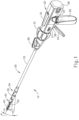
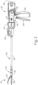
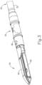
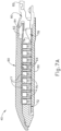
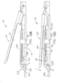
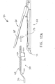
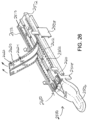
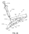
- FIG. 1 depicts an exemplary surgical stapling and severing instrument (10) that includes a handle assembly (20), a shaft assembly (30), and an end effector (40).
- End effector (40) and the distal portion of shaft assembly (30) are sized for insertion, in a nonarticulated state as depicted in FIG. 1 , through a trocar cannula to a surgical site in a patient for performing a surgical procedure.
- a trocar may be inserted in a patient's abdomen, between two of the patient's ribs, or elsewhere.
- instrument (10) is used without a trocar.
- end effector (40) and the distal portion of shaft assembly (30) may be inserted directly through a thoracotomy or other type of incision.
- terms such as “proximal” and “distal” are used herein with reference to a clinician gripping handle assembly (20) of instrument (10).
- end effector (40) is distal with respect to the more proximal handle assembly (20).
- spatial terms such as “vertical” and “horizontal” are used herein with respect to the drawings.
- surgical instruments are used in many orientations and positions, and these terms are not intended to be limiting and absolute.
- handle assembly (20) of the present example comprises pistol grip (22), a closure trigger (24), and a firing trigger (26). Each trigger (24, 26) is selectively pivotable toward and away from pistol grip (22) as will be described in greater detail below.
- Handle assembly (20) further includes an anvil release button (25), a firing beam reverse switch (27), and a removable battery pack (28). These components will also be described in greater detail below.
- handle assembly (20) may have a variety of other components, features, and operabilities, in addition to or in lieu of any of those noted above.
- Other suitable configurations for handle assembly (20) will be apparent to those of ordinary skill in the art in view of the teachings herein.
- shaft assembly (30) of the present example comprises an outer closure tube (32), an articulation section (34), and a closure ring (36), which is further coupled with end effector (40).
- Closure tube (32) extends along the length of shaft assembly (30).
- Closure ring (36) is positioned distal to articulation section (34).
- Closure tube (32) and closure ring (36) are configured to translate longitudinally relative to handle assembly (20). Longitudinal translation of closure tube (32) is communicated to closure ring (36) via articulation section (34). Exemplary features that may be used to provide longitudinal translation of closure tube (32) and closure ring (36) will be described in greater detail below.
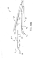
- Articulation section (34) is operable to laterally deflect closure ring (36) and end effector (40) laterally away from the longitudinal axis (LA) of shaft assembly (30) at a desired angle ( ⁇ ). End effector (40) may thereby reach behind an organ or approach tissue from a desired angle or for other reasons.
- articulation section (34) enables deflection of end effector (40) along a single plane.
- articulation section (34) enables deflection of end effector along more than one plane.
- articulation is controlled through an articulation control knob (35) which is located at the proximal end of shaft assembly (30).
- Knob (35) is rotatable about an axis that is perpendicular to the longitudinal axis (LA) of shaft assembly (30).
- Closure ring (36) and end effector (40) pivot about an axis that is perpendicular to the longitudinal axis (LA) of shaft assembly (30) in response to rotation of knob (35).
- rotation of knob (35) clockwise may cause corresponding clockwise pivoting of closure ring (36) and end effector (40) at articulation section (34).
- Articulation section (34) is configured to communicate longitudinal translation of closure tube (32) to closure ring (36), regardless of whether articulation section (34) is in a straight configuration or an articulated configuration.
- articulation section (34) and/or articulation control knob (35) are/is constructed and operable in accordance with at least some of the teachings of U.S. Pub. No. 2014/0243801, entitled “Surgical Instrument End Effector Articulation Drive with Pinion and Opposing Racks,” published August 28, 2014 .
- Articulation section (34) may also be constructed and operable in accordance with at least some of the teachings of U.S. Pat. App. No. 14/314,125, entitled “Articulation Drive Features for Surgical Stapler,” filed June 25, 2014 ; and/or in accordance with the various teachings below.
- Other suitable forms that articulation section (34) and articulation knob (35) may take will be apparent to those of ordinary skill in the art in view of the teachings herein.
- shaft assembly (30) of the present example further includes a rotation knob (31).
- Rotation knob (31) is operable to rotate the entire shaft assembly (30) and end effector (40) relative to handle assembly (20) about the longitudinal axis (LA) of shaft assembly (30).
- rotation knob (31) is operable to selectively lock the angular position of shaft assembly (30) and end effector (40) relative to handle assembly (20) about the longitudinal axis (LA) of shaft assembly (30).
- rotation knob (31) may be translatable between a first longitudinal position, in which shaft assembly (30) and end effector (40) are rotatable relative to handle assembly (20) about the longitudinal axis (LA) of shaft assembly (30); and a second longitudinal position, in which shaft assembly (30) and end effector (40) are not rotatable relative to handle assembly (20) about the longitudinal axis (LA) of shaft assembly (30).
- shaft assembly (30) may have a variety of other components, features, and operabilities, in addition to or in lieu of any of those noted above.
- at least part of shaft assembly (30) is constructed in accordance with at least some of the teachings of U.S. Pub. No. 2014/0239038, entitled "Surgical Instrument with Multi-Diameter Shaft,” published August 28, 2014 ,.
- Other suitable configurations for shaft assembly (30) will be apparent to those of ordinary skill in the art in view of the teachings herein.
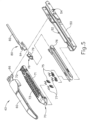
- end effector (40) of the present example includes a lower jaw (50) and a pivotable anvil (60).
- Anvil (60) includes a pair of integral, outwardly extending pins (66) that are disposed in corresponding curved slots (54) of lower jaw (50). Pins (66) and slots (54) are shown in FIG. 5 .
- Anvil (60) is pivotable toward and away from lower jaw (50) between an open position (shown in FIGS. 2 and 4 ) and a closed position (shown in FIGS. 1 , 3 , and 7A-7B ).
- anvil (60) pivots about an axis that is defined by pins (66), which slide along curved slots (54) of lower jaw (50) as anvil (60) moves toward lower jaw (50).
- the pivot axis translates along the path defined by slots (54) while anvil (60) simultaneously pivots about that axis.
- the pivot axis may slide along slots (54) first, with anvil (60) then pivoting about the pivot axis after the pivot axis has slid a certain distance along the slots (54).
- pivotal movement is encompassed within terms such as “pivot,” “pivots,” “pivotal,” “pivotable,” “pivoting,” and the like.
- some versions may provide pivotal movement of anvil (60) about an axis that remains fixed and does not translate within a slot or channel, etc.
- lower jaw (50) of the present example defines a channel (52) that is configured to receive a staple cartridge (70).
- Staple cartridge (70) may be inserted into channel (52), end effector (40) may be actuated, and then staple cartridge (70) may be removed and replaced with another staple cartridge (70).
- Lower jaw (50) thus releasably retains staple cartridge (70) in alignment with anvil (60) for actuation of end effector (40).
- lower jaw (50) is constructed in accordance with at least some of the teachings of U.S. Pub. No. 2014/0239044, entitled "Installation Features for Surgical Instrument End Effector Cartridge," published August 28, 2014 .
- Other suitable forms that lower jaw (50) may take will be apparent to those of ordinary skill in the art in view of the teachings herein.
- staple cartridge (70) of the present example comprises a cartridge body (71) and a tray (76) secured to the underside of cartridge body (71).
- the upper side of cartridge body (71) presents a deck (73), against which tissue may be compressed when anvil (60) is in a closed position.
- Cartridge body (71) further defines a longitudinally extending channel (72) and a plurality of staple pockets (74).
- a staple (77) is positioned in each staple pocket (74).
- a staple driver (75) is also positioned in each staple pocket (74), underneath a corresponding staple (77), and above tray (76).
- staple drivers (75) are operable to translate upwardly in staple pockets (74) to thereby drive staples (77) upwardly through staple pockets (74) and into engagement with anvil (60).
- Staple drivers (75) are driven upwardly by a wedge sled (78), which is captured between cartridge body (71) and tray (76), and which translates longitudinally through cartridge body (71).
- Wedge sled (78) includes a pair of obliquely angled cam surfaces (79), which are configured to engage staple drivers (75) and thereby drive staple drivers (75) upwardly as wedge sled (78) translates longitudinally through cartridge (70). For instance, when wedge sled (78) is in a proximal position as shown in FIG.
- staple drivers (75) are in downward positions and staples (77) are located in staple pockets (74).
- wedge sled (78) As wedge sled (78) is driven to the distal position shown in FIG. 7B by a translating knife member (80), wedge sled (78) drives staple drivers (75) upwardly, thereby driving staples (77) out of staple pockets (74) and into staple forming pockets (64) that are formed in the underside (65) of anvil (60).
- staple drivers (75) translate along a vertical dimension as wedge sled (78) translates along a horizontal dimension.
- staple cartridge (70) may be varied in numerous ways.
- staple cartridge (70) of the present example includes two longitudinally extending rows of staple pockets (74) on one side of channel (72); and another set of two longitudinally extending rows of staple pockets (74) on the other side of channel (72).
- staple cartridge (70) includes three, one, or some other number of staple pockets (74) on each side of channel (72).
- staple cartridge (70) is constructed and operable in accordance with at least some of the teachings of U. U.S. Patent App. No. 13/780,106, entitled "Integrated Tissue Positioning and Jaw Alignment Features for Surgical Stapler," filed February 28, 2013 .
- staple cartridge (70) may be constructed and operable in accordance with at least some of the teachings of U.S. Pub. No. 2014/0239044, entitled “Installation Features for Surgical Instrument End Effector Cartridge,” published August 28, 2014 .
- Other suitable forms that staple cartridge (70) may take will be apparent to those of ordinary skill in the art in view of the teachings herein.
- anvil (60) of the present example comprises a longitudinally extending channel (62) and a plurality of staple forming pockets (64).
- Channel (62) is configured to align with channel (72) of staple cartridge (70) when anvil (60) is in a closed position.
- Each staple forming pocket (64) is positioned to lie over a corresponding staple pocket (74) of staple cartridge (70) when anvil (60) is in a closed position.
- Staple forming pockets (64) are configured to deform the legs of staples (77) when staples (77) are driven through tissue and into anvil (60).
- staple forming pockets (64) are configured to bend the legs of staples (77) to secure the formed staples (77) in the tissue.
- Anvil (60) may be constructed in accordance with at least some of the teachings of U.S. Pub. No. 2014/0239042, entitled “Integrated Tissue Positioning and Jaw Alignment Features for Surgical Stapler,” published August 28, 2014 ; at least some of the teachings of U.S. Pub. No. 2014/0239036, entitled “Jaw Closure Feature for End Effector of Surgical Instrument,” published August 28, 2014 ; and/or at least some of the teachings of U.S. Pub. No. 2014/0239037, entitled “Staple Forming Features for Surgical Stapling Instrument,” published August 28, 2014 .
- Other suitable forms that anvil (60) may take will be apparent to those of ordinary skill in the art in view of the teachings herein.
- a knife member (80) is configured to translate through end effector (40). As best seen in FIGS. 5 and 7A-7B , knife member (80) is secured to the distal end of a firing beam (82), which extends through a portion of shaft assembly (30). As best seen in FIGS. 4 and 6 , knife member (80) is positioned in channels (62, 72) of anvil (60) and staple cartridge (70). Knife member (80) includes a distally presented cutting edge (84) that is configured to sever tissue that is compressed between anvil (60) and deck (73) of staple cartridge (70) as knife member (80) translates distally through end effector (40). As noted above and as shown in FIGS.
- knife member (80) also drives wedge sled (78) distally as knife member (80) translates distally through end effector (40), thereby driving staples (77) through tissue and against anvil (60) into formation.
- wedge sled (78) distally as knife member (80) translates distally through end effector (40), thereby driving staples (77) through tissue and against anvil (60) into formation.
- end effector (40) includes lockout features that are configured to prevent knife member (80) from advancing distally through end effector (40) when a staple cartridge (70) is not inserted in lower jaw (50).
- end effector (40) may include lockout features that are configured to prevent knife member (80) from advancing distally through end effector (40) when a staple cartridge (70) that has already been actuated once (e.g., with all staples (77) deployed therefrom) is inserted in lower jaw (50).
- lockout features may be configured in accordance with at least some of the teachings of U.S. Pub. No.
- anvil (60) is driven toward lower jaw (50) by advancing closure ring (36) distally relative to end effector (40).
- Closure ring (36) cooperates with anvil (60) through a camming action to drive anvil (60) toward lower jaw (50) in response to distal translation of closure ring (36) relative to end effector (40).
- closure ring (36) may cooperate with anvil (60) to open anvil (60) away from lower jaw (50) in response to proximal translation of closure ring (36) relative to end effector (40).
- closure ring (36) and anvil (60) may interact in accordance with at least some of the teachings of U.S. Pub. No.
- handle assembly (20) includes a pistol grip (22) and a closure trigger (24).
- anvil (60) is closed toward lower jaw (50) in response to distal advancement of closure ring (36).
- closure trigger (24) is pivotable toward pistol grip (22) to drive closure tube (32) and closure ring (36) distally.
- suitable components that may be used to convert pivotal movement of closure trigger (24) toward pistol grip (22) into distal translation of closure tube (32) and closure ring (36) relative to handle assembly (20) will be apparent to those of ordinary skill in the art in view of the teachings herein.
- closure trigger (24) When closure trigger (24) reaches a fully pivoted state, such that anvil (60) is in a fully closed position relative to lower jaw (50), locking features in handle assembly (20) lock the position of trigger (24) and closure tube (32), thereby locking anvil (60) in a fully closed position relative to lower jaw (50). These locking features are released by actuation of anvil release button (25).
- Anvil release button (25) is configured and positioned to be actuated by the thumb of the operator hand that grasps pistol grip (22).
- the operator may grasp pistol grip (22) with one hand, actuate closure trigger (24) with one or more fingers of the same hand, and then actuate anvil release button (25) with the thumb of the same hand, without ever needing to release the grasp of pistol grip (22) with the same hand.
- closure trigger (24) with one or more fingers of the same hand
- anvil release button (25) with the thumb of the same hand
- Other suitable features that may be used to actuate anvil (60) will be apparent to those of ordinary skill in the art in view of the teachings herein.
- instrument (10) provides motorized control of firing beam (82).
- instrument (10) includes motorized components that are configured to drive firing beam (82) distally in response to pivoting of firing trigger (26) toward pistol grip (22).
- a motor (not shown) is contained in pistol grip (22) and receives power from battery pack (28). This motor is coupled with a transmission assembly (not shown) that converts rotary motion of a drive shaft of the motor into linear translation of firing beam (82).
- firing beam (82) may only be advanced distally when anvil (60) is in a fully closed position relative to lower jaw (50). After firing beam (82) is advanced distally to sever tissue and drive staples (77) as described above with reference to FIGS.
- the drive assembly for firing beam (82) may be automatically reversed to drive firing beam (82) proximally back to the retracted position (e.g., back from the position shown in FIG. 7B to the position shown in FIG. 7A ).
- the operator may actuate firing beam reverse switch (27), which may reverse the drive assembly for firing beam (82) in order to retract firing beam (82) to a proximal position.
- Handle assembly (20) of the present example further includes a bailout feature (21), which is operable to provide a mechanical bailout allowing the operator to manually retract firing beam (82) proximally (e.g., in the event of power loss while firing beam (82) is in a distal position, etc.).
- the features that are operable to provide motorized actuation of firing beam (82) may be configured and operable in accordance with at least some of the teachings of U.S. Pat. No. 8,210,411, entitled “Motor-Driven Surgical Instrument,” issued July 3, 2012 .
- the features that are operable to provide motorized actuation of firing beam (82) may be configured and operable in accordance with at least some of the teachings of U.S. Pat. No. 8,453,914, entitled “Motor-Driven Surgical Cutting Instrument with Electric Actuator Directional Control Assembly,” issued June 4, 2013 .
- the features that are operable to provide motorized actuation of firing beam (82) may be configured and operable in accordance with at least some of the teachings of U.S. Patent App. No. 14/226,142, entitled “Surgical Instrument Comprising a Sensor System,” filed March 26, 2014 .
- firing beam (82) may be manually actuated in accordance with at least some of the teachings of any other reference cited herein.
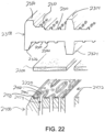
- FIG. 8 shows end effector (40) having been actuated through a single stroke through tissue (90).
- cutting edge (84) obscured in FIG. 8
- staple drivers (75) have driven two alternating rows of staples (77) through the tissue (90) on each side of the cut line produced by cutting edge (84).
- Staples (77) are all oriented substantially parallel to the cut line in this example, though it should be understood that staples (77) may be positioned at any suitable orientations.
- end effector (40) is withdrawn from the trocar after the first stroke is complete, the spent staple cartridge (70) is replaced with a new staple cartridge (70), and end effector (40) is then again inserted through the trocar to reach the stapling site for further cutting and stapling. This process may be repeated until the desired amount of cuts and staples (77) have been provided.
- Anvil (60) may need to be closed to facilitate insertion and withdrawal through the trocar; and anvil (60) may need to be opened to facilitate replacement of staple cartridge (70).
- cutting edge (84) may cut tissue substantially contemporaneously with staples (77) being driven through tissue during each actuation stroke.
- cutting edge (84) just slightly lags behind driving of staples (77), such that a staple (47) is driven through the tissue just before cutting edge (84) passes through the same region of tissue, though it should be understood that this order may be reversed or that cutting edge (84) may be directly synchronized with adjacent staples.
- FIG. 8 shows end effector (40) being actuated in two layers (92, 94) of tissue (90), it should be understood that end effector (40) may be actuated through a single layer of tissue (90) or more than two layers (92, 94) of tissue.
- FIG. 8 shows end effector (40) being actuated in two substantially flat, apposed planar layers (92, 94) of tissue, it should be understood that end effector (40) may also be actuated across a tubular structure such as a blood vessel, a section of the gastrointestinal tract, etc.
- FIG. 8 should therefore not be viewed as demonstrating any limitation on the contemplated uses for end effector (40).
- instrument (10) may be used will be apparent to those of ordinary skill in the art in view of the teachings herein.
- instrument (10) may be configured and operable in accordance with any of the various references cited herein. Additional exemplary modifications that may be provided for instrument (10) will be described in greater detail below. Various suitable ways in which the below teachings may be incorporated into instrument (10) will be apparent to those of ordinary skill in the art. Similarly, various suitable ways in which the below teachings may be combined with various teachings of the references cited herein will be apparent to those of ordinary skill in the art. It should therefore be understood that the teachings below may be readily incorporated into the various instruments taught in the various references that are cited herein. It should also be understood that the below teachings are not limited to instrument (10) or devices taught in the references cited herein.
- end effector (40) may be desirable in some instances to equip end effector (40) with a buttress material to reinforce the mechanical fastening of tissue (90) provided by staples (77).
- a buttress may prevent the applied staples (77) from pulling through tissue (90) and may otherwise reduce a risk of tissue (90) tearing at or near the site of applied staples (77).
- a buttress may provide various other kinds of effects such as spacing or gap-filling, administration of therapeutic agents, and/or other effects.
- a buttress may be provided on deck (73) of staple cartridge (70).
- a buttress may be provided on the surface of anvil (60) that faces staple cartridge (70). It should also be understood that a first buttress may be provided on deck (73) of staple cartridge (70) while a second buttress is provided on anvil (60) of the same end effector (40). Various examples of forms that a buttress may take will be described in greater detail below. Various ways in which a buttress may be secured to a staple cartridge (70) or an anvil (60) will also be described in greater detail below.
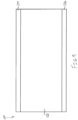
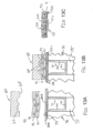
- FIG. 9 shows an exemplary buttress assembly (100) with a basic composition.
- Buttress assembly (100) of this example comprises a buttress body (102), an upper adhesive layer (104), and a lower adhesive layer (106).
- buttress body (102) comprises a strong yet flexible material configured to structurally support a line of staples (77).
- buttress body (102) may comprise a material including, for example, a hemostatic agent such as fibrin to assist in coagulating blood and reduce bleeding at the severed and/or stapled surgical site along tissue (90).
- buttress body (102) may comprise other adjuncts or hemostatic agents such as thrombin may be used such that buttress body (102) may assist to coagulate blood and reduce the amount of bleeding at the surgical site.
- the hemostatic abilities of such adjuncts may also contribute to the use of such adjuncts as adhesives and sealants.
- the agents may assist to coagulate blood at a surgical site, which allows tissue surrounding such blood to stick together and may prevent leaks along the stapled tissue site, for example.
- Other adjuncts or reagents that may be incorporated into buttress body (102) may further include but are not limited to medical fluid or matrix components.
- buttress body (102) may include natural or genetically engineered absorbable polymers or synthetic absorbable polymers, or mixtures thereof.
- Merely illustrative examples of natural or genetically engineered absorbable polymers are proteins, polysaccharides and combinations thereof.
- proteins that may be used include prothrombin, thrombin, fibrinogen, fibrin, fibronectin, heparinase, Factor X/Xa, Factor VII/VIla, Factor IX/IXa, Factor XI/XIa, Factor XII/XIIa, tissue factor, batroxobin, ancrod, ecarin, von Willebrand Factor, collagen, elastin, albumin, gelatin, platelet surface glycoproteins, vasopressin, vasopressin analogs, epinephrine, selectin, procoagulant venom, plasminogen activator inhibitor, platelet activating agents, synthetic peptides having hemostatic activity, and/or combinations thereof.
- Polysaccharides include, without limitation, cellulose, alkyl cellulose, e.g. methylcellulose, alkylhydroxyalkyl cellulose, hydroxyalkyl cellulose, cellulose sulfate, salts of carboxymethyl cellulose, carboxymethyl cellulose, carboxyethyl cellulose, chitin, carboxymethyl chitin, hyaluronic acid, salts of hyaluronic acid, alginate, alginic acid, propylene glycol alginate, glycogen, dextran, dextran sulfate, curdlan, pectin, pullulan, xanthan, chondroitin, chondroitin sulfates, carboxymethyl dextran, carboxymethyl chitosan, chitosan, heparin, heparin sulfate, heparan, heparan sulfate, dermatan sulfate, keratan sulfate, carrageenans,
- Examples of synthetic absorbable polymers are aliphatic polyester polymers, copolymers, and/or combinations thereof.
- the aliphatic polyesters are typically synthesized in a ring opening polymerization of monomers including, but not limited to, lactic acid, lactide (including L-, D-, meso and D, L mixtures), glycolic acid, glycolide, ⁇ -caprolactone, p-dioxanone (1,4-dioxan-2-one) , and trimethylene carbonate (1,3-dioxan-2-one).
- lactide including L-, D-, meso and D, L mixtures
- glycolic acid glycolide
- ⁇ -caprolactone p-dioxanone
- trimethylene carbonate 1,3-dioxan-2-one
- Buttress body (102) may alternatively comprise a fibrous pad, a foam, a mesh, a weave, and/or another structure capable of containing an adhesive and/or other type of medical fluid.
- buttress body (102) may simply comprise a mesh, a weave, and/or some other structure that is constructed to provide structural support or integrity to a line of staples (77) applied through tissue (90).
- Such a material and structure may be relatively thin and in some instances may be substantially non-compressible.
- buttress body (102) may be constructed in accordance with at least some of the teachings of U.S. Patent Pub. No.
- Patent Pub. No. 2013/0037596 entitled “Device for Applying Adjunct in Endoscopic Procedure,” published February 14, 2013 ; U.S. Patent Pub. No. 2013/0062393, entitled “Resistive Heated Surgical Staple Cartridge with Phase Change Sealant,” published March 14, 2013 ; U.S. Patent Pub. No. 2013/0075446, entitled “Surgical Staple Assembly with Hemostatic Feature,” published March 28, 2013 ; U.S. Patent Pub. No. 2013/0062394, entitled “Surgical Staple Cartridge with Self-Dispensing Staple Buttress,” published March 14, 2013 ; U.S. Patent Pub. No.
- 2013/0075445 entitled “Anvil Cartridge for Surgical Fastening Device,” published March 28, 2013 ;
- U.S. Patent Pub. No. 2013/0075447 entitled “Adjunct Therapy for Applying Hemostatic Agent,” published March 28, 2013 ;
- U.S. Patent Pub. No. 2013/0256367 entitled “Tissue Thickness Compensator Comprising a Plurality of Medicaments,” published October 3, 2013 .
- buttress body (102) comprises a woven mesh of VICRYL ® (polyglactin 910) material by Ethicon US, LLC.
- VICRYL ® woven mesh is prepared from a synthetic absorbable copolymer of glycolide and lactide, derived respectively from glycolic and lactic acids. This tightly woven mesh is prepared from uncoated, undyed fiber identical in composition to that used in VICRYL ® synthetic absorbable suture, which has been found to be inert, nonantigenic, nonpyrogenic, and to elicit only a mild tissue reaction during absorption.
- VICRYL ® woven mesh is intended for use as a buttress to provide temporary support during the healing process.
- any other suitable materials or combinations of materials may be used in addition to or as an alternative to VICRYL ® material to form buttress body (102).
- buttress body (102) is formed as a mesh
- buttress body (102) may be formed as a woven mesh, a knitted mesh, or a warp knitted mesh. Regardless of whether buttress body (102) is formed as a mesh or not, buttress body (102) is porous in some examples.
- an adhesive layer (104, 106) may be provided on buttress body (102) in order to adhere buttress body (102) to underside (65) of anvil (60) or deck (73) of staple cartridge (70).
- the material forming adhesive layer (104, 106) may pass through buttress body (102) to reach the outer surface of buttress body (102) that is opposite to the surface on which adhesive layer (104, 106) is disposed.
- upper adhesive layer (104) may be used to secure buttress assembly (100) to the underside (304) of a retainer (300) as will be described in greater detail below; while lower adhesive layer (106) is used to secure buttress assembly (100) to deck (73) of staple cartridge (70).
- lower adhesive layer (106) is configured to provide stronger adherence than upper adhesive layer (104).
- retainer (300) e.g., flanges, clips, etc.
- retainer (300) e.g., flanges, clips, etc.
- retainer (300) e.g., flanges, clips, etc.
- retainer (300) e.g., flanges, clips, etc.
- an adhesive material may be applied to the lower surface of a porous version of buttress body (102) to form lower adhesive layer (106), and some of that adhesive material may pass through buttress body (102) to form upper adhesive layer (104).
- lower adhesive layer (106) ultimately has more adhesive material than upper adhesive layer (104), such that lower adhesive layer (106) provides greater adhesion than upper adhesive layer (104).
- lower adhesive layer (106) may be used to secure buttress assembly (100) to the upper side (302) of a retainer (300) as will be described in greater detail below; while upper adhesive layer (104) is used to secure buttress assembly to underside (65) of anvil (60) of end effector (40).
- upper adhesive layer (104) is configured to provide stronger adherence than lower adhesive layer (106).
- retainer (300) e.g., flanges, clips, etc.
- retainer (300) e.g., flanges, clips, etc.
- retainer (300) are configured to selectively retain buttress assembly (100) against upper side (302) of retainer (300), such that lower adhesive layer (106) is omitted; while upper adhesive layer (104) is used to secure buttress assembly (100) to underside (65) of anvil (60).
- an adhesive material may be applied to the upper surface of a porous version of buttress body (102) to form upper adhesive layer (104), and some of that adhesive material may pass through buttress body (102) to form lower adhesive layer (106).
- upper adhesive layer (104) ultimately has more adhesive material than lower adhesive layer (106), such that upper adhesive layer (104) provides greater adhesion than lower adhesive layer (106).
- each adhesive layer (104, 106), as well as various forms that each adhesive layer (104, 106) may take, will be described in greater detail below.
- buttress assembly (100) may include an impermeable layer or a semi impermeable layer interposed between buttress body (102) and adhesive layer (102), to prevent or restrict migration of adhesive material from adhesive layer (104, 106) into buttress body (100).
- body (102) may be formed of a porous media (e.g., ETHISORB TM by Codman of Raynham, Massachusetts); while the semi impermeable layer may comprise polydioxanone (PDS).
- PDS polydioxanone
- buttress assembly (100) comprises an impermeable layer or a semi impermeable layer to prevent or restrict migration of adhesive material from adhesive layer (104, 106) into buttress body (100)
- a layer may be integrated into buttress body (102) such that the layer permits the adhesive to migrate at least partially into buttress body (102) but not across the full thickness of buttress body (102).
- an impermeable layer or a semi impermeable layer may be integrated into buttress assembly (100) to prevent or restrict migration of an adhesive material will be apparent to those of ordinary skill in the art in view of the teachings herein.
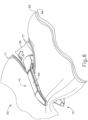
- FIGS. 10-12D show a combination of an exemplary buttress (200) with an exemplary retainer (300).
- Buttress (200) of this example may be constructed in accordance with the teachings above relating to buttress assembly (100) and/or in accordance with other teachings herein.
- Buttress (200) includes an upper side (202) and an underside (204).
- underside (204) includes an adhesive (e.g., like lower adhesive layer (106)) to secure buttress (200) to deck (73) of staple cartridge (70) as described in greater detail below.
- Retainer (300) of this example comprises an upper side (302), an underside (304), a distally projecting tongue (306), and a set of resilient latches (308).
- Upper side (302) and underside (304) are each generally flat in the present example, though it should be understood that upper side (302) and/or underside (304) may include various kinds of features as described elsewhere herein.
- Tongue (306) is configured to provide a grip for an operator, thereby facilitating grasping and handling of retainer (300) during use.
- Latches (308) are configured to releasably secure retainer (300) to lower jaw (50) of end effector (40) as will be described in greater detail below.
- retainer (300) may be formed of molded plastic. Alternatively, retainer (300) may be formed using any other suitable material(s) or technique(s).
- buttress (200) is secured to underside (304) of retainer (300), such that upper side (202) of buttress (200) apposes underside (304) of retainer (300).
- an adhesive such as upper adhesive layer (104) provides releasable adhesion of buttress (200) to underside (304) of retainer (300).
- retainer (300) includes one or more features (e.g., flanges, clips, etc.) that are configured to selectively retain buttress (200) against underside (304) of retainer (300).
- features e.g., flanges, clips, etc.
- the assembly formed by buttress (200) and retainer (300) may be placed before end effector (40) with anvil (60) in the open position.
- a peel-away film (not shown) is positioned over underside (204) of buttress (200) to protect buttress (200) and/or any adhesive material on underside (204) of buttress (200).
- the film is peeled away to expose underside (204) of buttress (200) before reaching the stage shown in FIG. 12A .
- Such a film may comprise polytetrafluoroethylene (PTFE) and/or any other suitable material(s).
- the assembly formed by buttress (200) and retainer (300) may then be placed on staple cartridge (70) such that underside (204) of buttress (200) apposingly contacts deck (73) of staple cartridge (70); and such that latches (308) are releasably secured to lower jaw (50) as shown in FIG. 12B .
- the operator may then drive anvil (60) toward the closed position as shown in FIG. 12C , eventually compressing buttress (200) against deck (73) of staple cartridge (70). Such compression may promote adhesion between underside (204) of buttress (200) and deck (73) of staple cartridge (70).
- anvil (60) After anvil (60) has been used to compress buttress (200) against deck (73) of staple cartridge (70), anvil (60) may be moved back to the open position as shown in FIG. 12D . As also shown in FIG. 12D , retainer (300) may then be pulled away from end effector (40), leaving behind buttress (200) adhered to deck (73) of staple cartridge (70). Upper side (202) of buttress (200) is exposed. End effector (40) is thus loaded with buttress (200) and ready for use in severing and stapling tissue (90).
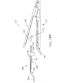
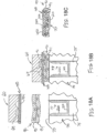
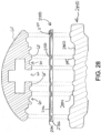
- FIGS. 13A-13C show an end effector (40) loaded with buttress (200) being used to drive a staple (77) through tissue (90).
- tissue (90) is placed between anvil (60) and staple cartridge (70), above buttress (200), with anvil (60) in the open position.
- anvil (60) is driven to the closed position, compressing tissue (90) against buttress (200) and staple cartridge (70).
- End effector (40) is then actuated as described above, driving staple (77) through buttress (200) and tissue (90).
- crown (210) of driven staple (77) captures and retains buttress (200) against layer (94) of tissue (90).
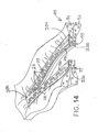
- a series of staples (77) will similarly capture and retain buttress (200) against layer (94) of tissue (90), thereby securing buttress (200) to tissue (90) as shown in FIG. 14 .
- end effector (40) is pulled away from tissue (90) after deploying staples (77) and buttress (200)
- buttress (200) disengages deck (73) of staple cartridge (70), such that buttress (200) remains secured to tissue (90) with staples (77).
- Buttress (200) thus provides structural reinforcement to the lines of staples (77).
- knife member (80) also cuts through a centerline of buttress (200), separating buttress (200) into two sections (230, 240), such that each section (230, 240) remains secured to a respective severed region of tissue (90).
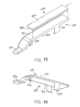
- FIGS. 15-17B show a combination of an exemplary buttress (400) with retainer (300).
- Buttress (400) of this example may be constructed in accordance with the teachings above relating to buttress assembly (100) and/or in accordance with other teachings herein.
- Buttress (400) includes an upper side (402) and an underside (404).
- upper side (402) includes an adhesive (e.g., like upper adhesive layer (1064) to secure buttress (200) to underside (65) of anvil (60) as described in greater detail below.
- buttress (400) is secured to upper side (302) of retainer (300), such that underside (404) of buttress (400) apposes upper side (302) of retainer (300).
- an adhesive such as lower adhesive layer (106) provides releasable adhesion of buttress (400) to upper side (302) of retainer (300).
- retainer (300) includes one or more features (e.g., flanges, clips, etc.) that are configured to selectively retain buttress (400) against upper side (302) of retainer (300).
- features e.g., flanges, clips, etc.
- the assembly formed by buttress (400) and retainer (300) may be placed before end effector (40) with anvil (60) in the open position.
- a peel-away film (not shown) is positioned over upper side (402) of buttress (400) to protect buttress (400) and/or any adhesive material on upper side (402) of buttress (400).
- the film is peeled away to expose upper side (402) of buttress (400) before reaching the stage shown in FIG. 17A .
- Such a film may comprise polytetrafluoroethylene (PTFE) and/or any other suitable material(s).
- the assembly formed by buttress (400) and retainer (300) may then be placed on staple cartridge (70) such that latches (308) are releasably secured to lower jaw (50) as described above.
- the operator may then drive anvil (60) toward the closed position as described above, eventually compressing buttress (400) underside (65) of anvil (60). Such compression may promote adhesion between upper side (402) of buttress (400) and underside (65) of anvil (60).
- anvil (60) may be moved back to the open position as shown in FIG. 17B .
- FIG. 17B As also shown in FIG.
- retainer (300) may then be pulled away from end effector (40), leaving behind buttress (400) adhered to underside (65) of anvil (60). Underside (402) of buttress (400) is exposed. End effector (40) is thus loaded with buttress (400) and ready for use in severing and stapling tissue (90).
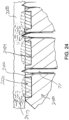
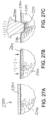
- FIGS. 18A-18C show an end effector (40) loaded with buttress (400) being used to drive a staple (77) through tissue (90).
- tissue (90) is placed between anvil (60) and staple cartridge (70), below buttress (400), with anvil (60) in the open position.
- anvil (60) is driven to the closed position, compressing tissue (90) against buttress (400) and staple cartridge (70).
- End effector (40) is then actuated as described above, driving staple (77) through buttress (400) and tissue (90).
- bent legs (220) of driven staple (77) capture and retains buttress (400) against layer (92) of tissue (90).
- a series of staples (77) will similarly capture and retain buttress (400) against layer (92) of tissue (90), thereby securing buttress (400) to tissue (90) as shown in FIG. 19 .
- anvil (60) is returned to the open position to enable end effector (40) to be pulled away from tissue (90) after deploying staples (77) and buttress (400)
- buttress (400) disengages underside (65) of anvil (60), such that buttress (400) remains secured to tissue (90) with staples (77).
- Buttress (400) thus provides structural reinforcement to the lines of staples (77).
- knife member (80) also cuts through a centerline of buttress (400), separating buttress (400) into two sections (430, 440), such that each section (430, 440) remains secured to a respective severed region of tissue (90).
- retainer (200) may be provided on underside (304) of retainer (300) while buttress (400) is provided on upper side (302) of retainer (300).
- retainer (200) may be provided on underside (304) of retainer (300) while buttress (400) is provided on upper side (302) of retainer (300).
- buttress (200) being provided on deck (73) of staple cartridge (70) and buttress (400) being provided on underside (65) of anvil (60) in the same end effector (400).
- buttress (200) being secured against layer (94) of tissue (90) by crowns (210) of staples (77) while buttress (400) is secured against layer (92) of tissue (90) by bent legs (220) of the same staples (77).
- a buttress assembly (100) may include at least one layer (104, 106) of adhesive material (or other form of adhesive material) that adheres buttress body (102) to either underside (65) of anvil (60) or deck (73) of staple cartridge (70).
- adhesive material or other form of adhesive material
- Such an adhesive material may provide proper positioning of buttress body (102) before and during actuation of end effector (40); then allow buttress body (102) to separate from end effector (40) after end effector (40) has been actuated, without causing damage to buttress body (102) that is substantial enough to compromise the proper subsequent functioning of buttress body (102). It may be desirable to minimize the impact of such an adhesive material on the functioning of firing beam (82) wedge sled (78), and staple drivers (75).
- the adhesive material should allow buttress body (102) to detach easily enough from an actuated end effector (40) to avoid tearing tissue (90) after staples (77) have been fired through the tissue and anvil (60) is moved to the open position.
- the adhesive material may include one or more components that provide a therapeutic effect, hemostatic effect, or other desired effect on tissue (90).
- the adhesive material may fill in at least part of the paths that are formed through tissue (90) and/or buttress body (102) by legs (220) of staple (77) being driven through tissue (90) and buttress body (102).
- the adhesive material for a buttress body (102) may be pressure sensitive.
- the adhesive material may be configured to take the form of surface irregularities of buttress body (102); in addition to or in lieu of taking the form of surface irregularities in underside (65) of anvil (60) and/or deck (73) of staple cartridge (70).
- Suitable adhesive materials may possess various other characteristics in addition to or in lieu of those above. Suitable adhesive materials may also be provided in various different kinds of compositions. Examples of various suitable compositions and configurations that may be used to form and provide an adhesive material for a buttress body (102), as well as various exemplary characteristics that such adhesive material may possess, are described in greater detail below.
- these examples of adhesive materials may be provided in lower adhesive layer (106). In addition or in the alternative, these examples of adhesive materials may be otherwise integrated into buttress body (102). It should therefore be understood that the adhesive material need not necessarily constitute a separate layer that is discretely identifiable as being different from a layer defined by buttress body (102).
- the adhesive material is formed by a copolymer of lactide and caprolactone (PLA/PCL).
- This composition may be provided at a ratio in the range of 20/80 to 60/40; or more particularly the range of 35/65 to 50/50.
- This composition may have a glass transition temperature (Tg) that is below 4°C, or more particularly below - 10°C.
- Tg glass transition temperature
- This composition may have a molecular weight in the range of 10,000 g/mol to 145,000 g/mol; or more particularly below 200,000 g/mol.
- the composition may have an inherent viscosity (IV) in the range of 1.0 dL/g to 2.0 dL/g.
- the adhesive material is formed by a copolymer of lactide and trimethylene carbonate (PLA/TMC).
- PLA/TMC lactide and trimethylene carbonate
- This composition may be provided at a ratio in the range of 20/80 to 50/50.
- the other characteristics may be within the same parameters set forth above with respect to the exemplary PLA/PCL composition.
- the PLA/TMC composition may have any other suitable characteristics.
- the adhesive material is formed by a copolymer of trimethylene carbonate and caprolactone (TMC/PCL).
- TMC/PCL trimethylene carbonate and caprolactone
- This composition may be provided at a ratio in the range of 20/80 to 80/20; or more particularly in the range of 50/50 to 60/40.
- This composition may have an inherent viscosity (IV) in the range of 0.3 dL/g to 3.0 dL/g; or more particularly in the range of 0.5 dL/g to 1.0 dL/g.
- This composition may have a crystallinity below 20%; or more particularly below 5%; or more particularly at 0% (i.e., a completely amorphous polymer).
- This composition may have a glass transition temperature (Tg) below 0°C; or more particularly below -20°C.
- the adhesive material is formed by a copolymer of caprolactone and glycolide (PCL/PGA).
- PCL/PGA copolymer of caprolactone and glycolide
- This composition may be provided at a ratio in the range of 45/55 to 85/15; or more particularly in the range of 40/60 to 65/35; or more particularly in the range of 50/50 to 65/35.
- This composition may have an inherent viscosity (IV) in the range of 0.2 dL/g to 3.0 dL/g; or more particularly in the range of 1.0 dL/g to 2.0 dL/g.
- This composition may have a molecular weight in the range of 100,000 g/mol to 200,000 g/mol.
- This composition may have a crystallinity below 20%; or more particularly below 5%; or more particularly at 0% (i.e., a completely amorphous polymer).
- This composition may have a glass transition temperature (Tg) below 0°C; or more particularly below -20°C.
- Tg glass transition temperature
- One particular example of this composition has a ratio of 50/50 PCL/PGA; an inherent viscosity (IV) of 0.2; a molecular weight of 83,000 g/mol; and a glass transition temperature (Tg) of -19.4°.
- compositions has a ratio of 65/35 PCL/PGA; an inherent viscosity (IV) of 1.04 to 1.07; a molecular weight of 110,000 g/mol to 118,000 g/mol; and a glass transition temperature (Tg) in the range of -37.3° to -38.6°.
- exemplary synthetic based polymer compositions that may be used to form the adhesive material include the following: propanediol and caprolactone (PDO/PCL); a combination of propanediol, caprolactone, and trimethylene carbonate (PDO/PCUTMC), with very low to no crystallinity and a glass transition temperature (Tg) below 0°C; and a homopolymer poly(TMC), with an inherent viscosity (IV) of approximately 0.5 dL/g.
- PDO/PCL propanediol and caprolactone
- PDO/PCUTMC propanediol and caprolactone
- Tg glass transition temperature
- IV inherent viscosity
- suitable synthetic based polymer compositions will be apparent to those of ordinary skill in the art in view of the teachings herein.
- the adhesive material may include a blocky copolymer.
- a blocky copolymer that may be used in the adhesive material comprises blocky poly(TMC), with a low glass transition temperature (Tg).
- TMC blocky poly(TMC)
- Tg low glass transition temperature
- the blocky copolymer may be randomized. In some other instances, such as when the copolymer is amorphous (e.g., 0% crystallinity), the blocky copolymer may be ordered.
- the adhesive material may include various kinds of copolymer chain compositions.
- the copolymer chain composition may be branched with relatively short segments. This may further enhance the malleability experience.
- the copolymer chain may be linear.
- the copolymer may be cross-linked or star pattern. However, in versions where the copolymer is cross-linked, it may be desirable for the base copolymer segments to be more amorphous the more that those segment are cross-linked.
- the melting temperature (Tm) is a physiomechanical property of a polymer that may be selected to provide desired adhesive characteristics.
- the lower melting temperature (Tm) of a monomer component could limit the amount of the co-monomer needed to create a desired adhesive effect.
- polydioxanone (PDS) has a melting temperature (Tm) around approximately 110°C and a glass transition temperature (Tg) around approximately - 10°C.
- Tm melting temperature
- Tg glass transition temperature
- PCL caprolactone
- PSA pressure sensitive adhesive
- polydioxanone (PDS) copolymers with polyglycolide (PGA) or lactide (PLA) may provide desired adhesive effects. It may be desirable for such copolymers to have a glass transition temperature (Tg) that is below room temperature; a melting temperature (Tm) that is at or below room temperature; a crystallinity in the range of 10% to 0%; and an inherent viscosity (IV) that is less than 2.0 dL/g, or more particularly less than 1.0 dL/g.
- Tg glass transition temperature
- Tm melting temperature
- IV inherent viscosity
- the adhesive material may comprise a blended copolymer.
- the high and low molecular weight of the same pressure sensitive adhesive (PSA) copolymer may allow for the degradation rate to be adjusted without adjusting the polymer chemistry. As the low molecular weight version breaks down, its acid byproducts would then change the pH and effect the breakdown of the high molecular weight parts.
- Preferred blends of copolymers would include those that will not affect the crystallinity, low melting temperature (Tm), and low glass transition temperature (Tg) of the copolymers.
- the adhesive material may comprise polyurethane.
- the polyurethane may be provided as a pressure sensitive adhesive (PSA).
- PSA pressure sensitive adhesive
- polyurethane based pressure sensitive adhesives PSAs
- PSAs polyurethane based pressure sensitive adhesives
- PSAs may be prepared from isocyanates, polyols, and chain extenders.
- Pressure sensitive adhesives PSAs
- PSAs may also be prepared from 100% solids, waterborne, or solvent borne systems.
- the properties of polyurethane based pressure sensitive adhesives (PSAs) may be controlled by varying the ratio of isocyanates to polyols and chain extenders.
- the polyurethane may be provided in a flowable form.
- a flowable polyurethane based adhesive material may have an inherent viscosity (IV) that is less than 1.0 dL/g, or more particularly less than 0.5 dL/g; a glass transition temperature (Tg) that is in the range of -10°C and 10°C; or more particularly closer to - 10°C; and a consistency similar to that of honey or oil, if desired, with the proper inherent viscosity (IV).
- IV inherent viscosity
- absorbable synthetic based polymers are provided for merely illustrative purposes. Other suitable examples will be apparent to those of ordinary skill in the art in view of the teachings herein. It should also be understood that the foregoing examples of absorbable synthetic based polymers may be readily incorporated into the various teachings and examples provided below. In other words, the foregoing examples of absorbable synthetic based polymers may be readily incorporated into any example herein that refers to an adhesive material.
- the adhesive material comprises a hydrogel.
- the hydrogel may generally comprise a hydrophilic polymer network capable of absorbing and/or retaining fluids.
- An exemplary hydrogel material is glycol methacrylate.
- suitable hydrogel materials may comprise homopolymer hydrogels, copolymer hydrogels, multipolymer hydrogels, interpenetrating polymer hydrogels, and combinations thereof.
- the hydrogel may comprise microgels, nanogels, and combinations thereof.
- the hydrogel may further comprise a non-crosslinked hydrogel, a crosslinked hydrogel, and combinations thereof.
- the hydrogel may comprise chemical crosslinks, physical crosslinks, hydrophobic segments and/or water insoluble segments.
- the hydrogel may be chemically crosslinked by polymerization, small-molecule crosslinking, and/or polymer-polymer crosslinking.
- the hydrogel may be physically crosslinked by ionic interactions, hydrophobic interactions, hydrogen bonding interactions, sterocomplexation, and/or supramolecular chemistry.
- the hydrogel may be substantially insoluble due to the crosslinks, hydrophobic segments and/or water insoluble segments, but be expandable and/or swellable due to absorbing and/or retaining fluids.
- the precursor may crosslink with endogenous materials and/or tissues.
- hydrogels that may be used include multifunctional acrylates, hydroxyethylmethacrylate (HEMA), and elastomeric acrylates.
- HEMA hydroxyethylmethacrylate
- a hydrogel adhesive material may be constructed in accordance with at least some of the teachings of U.S. Pat. Pub. No. 2012/0241492, entitled “Tissue Thickness Compensator Comprising at Least One Medicament," published September 27, 2012 .
- Other suitable ways in which an adhesive material may be provided with hydrogel will be apparent to those of ordinary skill in the art in view of the teachings herein.
- Naturally based polymers that may be used to form an adhesive material include alginate (e.g., calcium alginate, calcium sodium alginate, etc.); hyaluronic acid, collagen (including gelatin), and polysaccharide.
- the polysaccharide may include cellulose, chitin, pectin, or arabinoxylans.
- the cellulose may comprise oxidized regenerated cellulose, carboxy-methylcellulose, carboxyethyl cellulose, hydroxypropyl cellulose, hydroxyethyl cellulose, or oxidized cellulose.
- the chitin may comprise chitosan (e.g., deacetylated chitin) or chitosan salts.
- Some versions of naturally based polymers that may be used to form an adhesive material may include a putty or wax-like material. Some such versions may be non-absorbable and may be similar to a conventional bone wax. For instance, the material may comprise beeswax with one or more of the paraffin, petroleum jelly, isopropyl palmitate, sesame oil, carbolic acid; or any other conventional bone wax composition. Some other versions of a putty or wax-like material that may be used to form an adhesive material for buttress body (102) may be absorbable or resorbable.
- some such versions may comprise HEMASORB ® putty by Abyrx, Ink of Irvington, New York, water-soluble alkylene copolymers (e.g., OSTENE by Baxter Healthcare Corporation of Deerfield, Illinois), glycerol, l-lactide, glycolide, polyethylene glycol (PEG), polyethylene oxide (PEO), or polyolefin elastomer (POE).
- the adhesive material may comprise polyethylene glycol (PEG) or a polyethylene glycol (PEG) copolymer with a molecular weight of less than 20,000 g/mol. Having the molecular weight in such a range may promote passage of the dissolved form of the adhesive through the kidneys.
- the adhesive material may be constructed in accordance with at least some of the teachings of U.S. Pat. No. 2,642,375, entitled “Hemostatic Compositions,” issued June 16, 1953 .
- Some polymer adhesives may include oxidized regenerated cellulose (ORC), which is a hemostatic agent.
- ORC oxidized regenerated cellulose
- a putty or wax-like composition may serve as a carrier for oxidized regenerated cellulose (ORC).
- ORC oxidized regenerated cellulose
- U.S. Patent Pub. No. 2012/0241493, entitled “Tissue Thickness Compensator Comprising Controlled Release and Expansion,” published September 27, 2012 discusses various ways in which oxidized regenerated cellulose (ORC) may be incorporated into various compositions. It should be understood that such teachings of U.S. Patent Pub. No. 2012/0241493 may be readily applied herein in the context of incorporating oxidized regenerated cellulose (ORC) into polymer adhesives, including but not limited to the putty or wax-like compositions referred to above.
- a flowable (i.e., low viscosity) adhesive material with buttress body (102), in addition to or as an alternative to having one or more adhesive layers (104, 106) on upper or lower surfaces of buttress body (102), to removably secure buttress assembly (100) to deck (73) of staple cartridge (70) or underside (65) of anvil (60).
- a composition that may be used to provide a flowable adhesive material is a 50/50 copolymer of caprolactone and glycolide (PCL/PGA).
- a flowable adhesive may be formulated in accordance with at least some of the teachings of U.S. Pub. No. 2005/0070929, entitled “Apparatus and Method for Attaching a Surgical Buttress to a Stapling Apparatus,” published March 31, 2005 .
- a suitable flowable adhesive material may include one or more elastomeric polymers or copolymers that have an inherent viscosity (IV) of from about 1.2 dL/g to about 4 dL/g, or more particularly an inherent viscosity (IV) of from about 1.2 dL/g to about 2 dL/g, or more particularly an inherent viscosity (IV) of from about 1.4 dL/g to about 2 dL/g as determined at 25°C in a 0.1 gram per deciliter (g/L) solution of polymer in hexafluoroisopropanol (HFIP).
- IV inherent viscosity
- the elastomeric polymer may exhibit a high percent elongation and a low modulus, while possessing good tensile strength and good recovery characteristics.
- the elastomeric polymer may exhibit a percent elongation greater than about 200, preferably greater than about 500. It may also exhibit a modulus (Young's Modulus) of less than about 27,579 kPa (4000 psi), or more particularly less than about 137,895 kPa (20,000 psi).
- the properties, which measure the degree of elasticity of the biodegradable elastomeric polymer, may be achieved while maintaining a tensile strength greater than about 3,447 kPa (500 psi), more particularly greater than about 6,895 kPa (1,000 psi); and a tear strength of greater than about 8.8 kN/m (50 lbs/inch), more particularly greater than about 14.0 kN/m (80 lbs/inch).
- Foam materials comprising elastomeric polymers may be formed by lyophilization, supercritical solvent foaming (e.g., as described in International Patent Pub. No. WO 91/09079, entitled “Use of Supercritical Fluids to Obtain Porous Sponges of Biodegradable Polymers” published June 27, 1991 ), gas injection extrusion, gas injection molding, or casting with an extractable material (e.g., salts, sugar or any other means known to those skilled in the art).
- an extractable material e.g., salts, sugar or any other means known to those skilled in the art.
- biodegradable, biocompatible elastomeric foams are prepared by lyophilization.
- One suitable method for lyophilizing elastomeric polymers to form an exemplary buttress assembly (100) is described in U.S. Pat.
- an aliphatic polyester may be generally prepared by a ring-opening polymerization of the desired proportions of one or more lactone monomers in the presence of an organometallic catalyst and an initiator at elevated temperatures.
- the organometallic catalyst preferably is a tin-based catalyst, e.g. stannous octoate, and is present in the monomer mixture at a molar ratio of monomer to catalyst ranging from about 15,000/1 to about 80,000/1.
- the initiator typically is an alkanol (such as 1-dodecanol), a polyol (such as 1,2-propanediol, 1,3-propanediol, diethylene glycol, or glycerol, polyethylene glycol)s, polypropylene glycol)s and poly(ethylene-co-propylene glycol)s), a hydroxyacid, or an amine, and is present in the monomer mixture at a molar ratio of monomer to initiator ranging from about 100/1 to about 5000/1.
- the polymerization typically is carried out at a temperature range from about 80°C. to about 220°C., more particularly from about 160°C. to 190°C., until the desired molecular weight and viscosity (IV) are achieved.
- the resulting material may be used to provide a flowable adhesive material for buttress assembly (100).
- the flowable adhesive material may comprise cellulosic and aliphatic ester homopolymers and copolymers made from polymers of the formula: [-O-R 11 -C(O)-] y , where R 11 is selected from the group consisting of -CR 12 H-, -(CH 2 ) 3 -O-, -CH 2 -CH 2 -O-CH 2 -, CR 12H-CH 2 , -(CH 2 ) 4 -, - (CH 2 ) z -O- and -(CH 2 ) z -C(O)-CH 2 -; R 12 is hydrogen or methyl; z is an integer in the range of from 1 to 7; and y is an integer in the range of from about 10 to about 20,000; blends of a viscous polyethylene glycol (PEG) liquid and a low melting solid polyethylene glycol (PEG) (solid at room temperature that melts at less than about 60°C
- releasable adhesive may be used as a releasable adhesive.
- the releasable adhesive may be flowable at body temperature (37°C.) and in some instances will flow at room temperatures (25°C.). These liquids will may further have a low yield point to avoid migration of the polymer.
- suitable tacky liquid copolymers are taught in U.S. Patent No. 5,824,333, entitled “Injectable Liquid Copolymers for Soft Tissue Repair and Augmentation," issued October 20, 1998 .
- tacky microdispersions may also be used such as those described in U.S. Pat. No. 5,599,852, entitled “Plylactone Homo- and Copolymers,” issued February 4, 1997 .
- a suitable flowable adhesive material may comprise a liquid copolymer composed of in the range of from about 65 mole percent to about 35 mole percent of epsilon-caprolactone, trimethylene carbonate, ether lactone (which for the purpose of this invention is defined to be 1,4-dioxepan-2-one and 1,5-dioxepan-2-one) repeating units or combinations thereof with the remainder of the polymer being a plurality of second lactone repeating units are preferred.
- the second lactone repeating units may be selected from the group consisting of glycolic acid repeating units, lactic acid repeating units, 1,4-dioxanone repeating units, 6,6-dialkyl-1,4-dioxepan-2-one, combinations thereof and blends thereof.
- epsilon-caprolactone, trimethylene carbonate, or an ether lactone may be copolymerized to provide a liquid copolymer.
- exemplary polymers that may be used as particulate solids are bioabsorbable polymers including homopolymers of poly(epsilon-caprolactone), poly(p-dioxanone), or poly(trimethylene carbonate), copolymers of epsilon-caprolactone and trimethylene carbonate, copolymers of epsilon-caprolactone and a plurality of second lactone repeating units.
- the second lactone repeating units may be selected from the group consisting of glycolic acid repeating units, lactic acid repeating units, 1,4-dioxanone repeating units, 1,4-dioxepan-2-one repeating units, 1,5-dioxepan-2-one repeating units and combinations thereof.
- the copolymers of epsilon-caprolactone may be composed of from 99 mole percent to 70 mole percent epsilon-caprolactone with the remainder of the polymer being a plurality of second lactone repeating units.
- the polymers may be linear, branched, or star branched; block copolymers or terpolymers; segmented block copolymers or terpolymers. These polymers will also be purified to substantially remove unreacted monomers that may cause an inflammatory reaction in tissue.
- liquid copolymers that may be used as a flowable, releasable adhesive are composed of in the range of from about 65 mole percent to about 35 mole percent epsilon-caprolactone or an ether lactone repeating unit with the remainder of the copolymer being trimethylene carbonate repeating units.
- terpolymers examples include terpolymers selected from the group consisting of poly(glycolide-co-epsilon-caprolactone-co-p-dioxanone) and poly(lactide-co-epsilon-caprolactone-co-p-dioxanone) wherein the mole percent of epsilon-caprolactone repeating units is from about 35 to about 65 mole percent.
- liquid copolymer for use as the flowable, releasable adhesive may be selected from the group consisting of poly(epsilon-caprolactone-co-trimethylene carbonate), poly(lactide-co-trimethylene carbonate), poly(epsilon-caprolactone-co-p-d- ioxanone), poly(trimethylene carbonate-co-p-dioxanone), poly(epsilon-caprolactone-co-lactide), poly(lactide-co-1,5-dioxepan-2-one- ), and poly(1,5-dioxepan-2-one-co-p-dioxanone), poly(lactide-co-1,4-dioxep- an-2-one), and poly(1,4-dioxepan-2-co-co
- the mole percent of epsilon-caprolactone, trimethylene carbonate or ether lactone repeating units in these polymers should be in the range of from about 35 to about 65 mole percent and more particularly in the range of from 40 to 60 mole percent. In some cases these liquid polymers will be statistically random copolymers. These polymers will also be purified to substantially remove unreacted monomers that may cause an inflammatory reaction in tissue.
- exemplary polymers used as the flowable, releasable adhesive have an inherent viscosity (IV) as determined in a 0.1 g/dL solution of hexafluoroisopropanol (HFIP) at 25°C. ranging from about 0.1 dL/g to about 0.8 dL/g, more particularly from about 0.1 dL/g to about 0.6 dL/g, and more particularly from 0.15 dL/g to 0.25 dL/g for liquid polymers.
- blends of liquid and solid polyethylene glycols (PEG) may be used as releasable adhesives.
- the liquid polyethylene glycols (PEG) may have a molecular weight from about 200 to about 600.
- the solid polyethylene glycols (PEG) may have a molecular weight from about 3400 to about 10,000. Generally it is theorized, but in no way limits the scope of this invention, that the low molecular weight liquid polyethylene glycols (PEG) plasticizes the solid polyethylene glycols (PEG) to render the solid polyethylene glycols (PEG) tacky. Consequently, in some versions, the majority of the composition is be the solid polyethylene glycols (PEG) and more particularly between about 50 and about 80 percent by weight of the composition will be solid polyethylene glycols (PEG).
- a liquid polyethylene glycol (PEG) with molecular weight of 400 may be blended with a solid polyethylene glycol (PEG) with a molecular weight of about 2,000 (PEG 2000).
- the ratio of PEG 400 to PEG 2000 may vary from about 40:60 to about 30:70.
- These blends may be formed by mixing the liquid polyethylene glycol (PEG) and the solid polyethylene glycol (PEG) with constant stirring in a heated water bath until the solid melts and a clear liquid solution is formed. After these solutions are allowed to cool and the resulting mixture may be tested for tackiness and used if the desired tackiness is obtained.
- compositions that may provide a flowable adhesive material will be apparent to those of ordinary skill in the art in view of the teachings herein.
- the below examples include various exemplary configurations through which one or more flowable adhesive materials may be combined with a buttress body (102) to removably secure buttress assembly (100) to deck (73) of staple cartridge (70) or underside (65) of anvil (60).
- the adhesive material comprises a synthetic based polymer such as those referred to herein.
- naturally based polymers may be incorporated with the below teachings.
- Retainer (2300) of the present example has an upper surface (2310) and a lower surface (2320).
- Upper surface (2310) includes a plurality of upwardly extending projections (2312); an upwardly projecting, longitudinally extending rib (2314); and a pair of upwardly projecting, longitudinally extending side rails (2316).
- Projections (2312) are configured and positioned to correspond with staple forming pockets (64) on underside (65) of anvil (60).
- Rib (2314) is sized to complement channel (62) of anvil (60).
- Lower surface (2320) includes a plurality of downwardly extending projections (2322); a downwardly projecting, longitudinally extending rib (2324); and a pair of downwardly projecting, longitudinally extending side rails (2326).
- Projections (2322) are configured and positioned to correspond with troughs (2404) that are formed in staple cartridge (2400) as will be described in greater detail below.
- Rib (2324) is sized to complement channel (2472)
- buttress bodies (2200) are laid over flowable adhesive material (2220) and contact the top surfaces of each ridge (2402). Buttress bodies (2200) and ridges (2402) thus cooperate to contain adhesive material (2220) in troughs (2404).
- flowable adhesive material (2220) may be introduced into troughs (2404), before or after buttress bodies (2200) are placed against staple cartridge (2400).
- flowable adhesive material (2220) may be injected into troughs (2404) as described above, before or after buttress bodies (2200) are placed against staple cartridge (2400).
- flowable adhesive material (2220) is positioned in staple forming pockets (64) of anvil (60).
- Such flowable adhesive material (2220) may be provided and contained in staple forming pockets (64) using any of the techniques described above with respect to providing and containing flowable adhesive material (2220) in troughs (2404).
- buttress bodies (2200) may be configured with discrete droplets of adhesive material (2220), with a peel-away film layer used to contain the adhesive material (2220) in the form of discrete droplets, similar to buttress assembly (2000) described above.
- Other suitable ways in which flowable adhesive material (2220) may be provided and contained in staple forming pockets (64) will be apparent to those of ordinary skill in the art in view of the teachings herein.
- anvil (60) When retainer (2300) loaded with buttress bodies (2200) is positioned between anvil (60) and staple cartridge (2400), with flowable adhesive material (2220) in troughs (2404) and either in staple forming pockets (64) or in positions to enter staple forming pockets (64), anvil (60) may be brought to a closed position as shown in FIG. 23 .
- projections (2312) are configured to provide focused pressure to regions of buttress bodies (2200) at regions corresponding to staple forming pockets (64); while projections (2322) are configured to provide focused pressure to regions of buttress bodies (2200) at regions corresponding to troughs (2404).
- Ribs (2314, 2324) enter corresponding channels (62, 2472) and prevent flowable adhesive material (2220) from entering channels (62, 2472). Ribs (2314, 2324) may also ensure proper lateral alignment of retainer (2300) and buttress bodies (2200) with anvil (60) and staple cartridge (2400). Side rails (2316, 2326) are configured to further contain flowable adhesive material (2220). Side rails (2316, 2326) may also assist in ensuring proper lateral alignment of retainer (2300) and buttress bodies (2200) with anvil (60) and staple cartridge (2400).
- buttress bodies (2200) may each define a plurality of pockets that are configured to contain flowable adhesive material (2220) in the form of discrete droplets.
- a flat impermeable peel-away film is laid over flowable adhesive material (2220) and each buttress body (2200), containing flowable adhesive material (2220) in the pockets of buttress body (2200).
- such peel-away film also defines a plurality of pockets that are configured to cooperate with the pockets of buttress body (2220) to contain flowable adhesive material (2220) in the form of discrete droplets. It should be understood that such variations may be used in combination with staple cartridge (2400) or staple cartridge (70).
- each buttress body (2200) may include a plurality of discrete regions of increased thickness. In the pair of upper buttress bodies (2200), these discrete regions of increased thickness may be located at positions corresponding to staple forming pockets (64). In the pair of lower buttress bodies (2200), these discrete regions of increased thickness may be located at positions corresponding to troughs (2404). The discrete regions of increased thickness may serve functions similar to those of projections (2312, 2322), such that projections (2312, 2322) may be omitted. In particular, discrete regions of increased thickness in buttress bodies (2200) may provide focused pressure to regions of buttress bodies (2200) at regions corresponding to staple forming pockets (64) and troughs (2404). Each buttress body (2200) may also have regions of increased thickness at locations corresponding to channels (62, 2472), such that regions of increased thickness in buttress bodies (2200) may serve as structural substitutes for (and functional equivalents of) ribs (2314, 2324).
- FIGS. 25-26 show another exemplary alternative retainer (2500) that is configured for use with a buttress assembly (2600).
- Retainer (2500) of this example comprises a distally projecting tongue (2506); a set of resilient latches (2508); an upwardly projecting, longitudinally extending rib (2510); a pair of upwardly projecting, longitudinally extending side rails (2512); and a set of foam members (2520, 2522).
- tongue (2506) and latches (2508) may be configured and operable just like tongue (306) and latches (308) described above.
- retainer (2500) may be removably secured to lower jaw (50) to apply a buttress body to underside (65) of anvil (60).
- rib (2510) and rails (2512) may be configured and operable just like rib (2314) and side rails (2316) described above.
- rib (2510) and rails (2512) may assist in ensuring proper positioning of retainer (2500) and may further assist in containing flowable adhesive material at appropriate locations.
- Buttress assembly (2600) is configured substantially similar to buttress assembly (2000) described above.
- buttress assembly (2600) comprises a pair of buttress bodies (2602), each having a layer of flowable adhesive material (2610, 2612) in discrete regions.
- each buttress body (2602) has a large distal region of flowable adhesive material (2610) and several smaller regions of flowable adhesive material (2612) proximal to the distal region of flowable adhesive material (2610).
- Buttress bodies (2602) may be configured in accordance with any buttress body described herein.
- an impermeable or semi-impermeable layer is positioned over each buttress body (2602), interposed between buttress body (2602) and flowable adhesive material (2610, 2612), to thereby prevent or restrict the flow of flowable adhesive material (2610, 2612) into buttress body (2602).
- An impermeable peel-away film (2620) is laid over flowable adhesive material (2610, 2612) and buttress body (2602).
- Film (2620) defines a plurality of pockets (2622, 2624) that are configured to contain flowable adhesive material (2610, 2612) in the form of discrete droplets.
- Film (2620) is configured to adhere to buttress body (2602) (or an impermeable layer or semi-impermeable layer that is laid over buttress body (2602)) during storage and transport of buttress assembly (2600), but may be peeled away to expose flowable adhesive material (2610, 2612) right before buttress assembly (2600) is installed on end effector (40).
- Pocket (2622) is larger than pockets (2624), such that pockets (2622) are sized to correspond with the larger size of distal region of flowable adhesive material (2610); while pockets are sized to correspond with the smaller size of smaller regions of flowable adhesive material (2612).
- Foam members (2520, 2522) comprise a pair of distal foam members (2520) and a pair of proximal foam members (2522).
- Foam members (2520, 2522) may comprise any suitable foam material.
- Each foam member (2520, 2522) is configured to provide an upward bias to buttress assembly (2600), though foam members (2520, 2522) are compressible. It should be understood that foam members (2520, 2522) may provide a homogenous pressure urging buttress assembly (2600) into engagement with underside (65) of anvil (60) when anvil (60) compresses buttress assembly (2600) against retainer (2500).
- foam members (2520, 2522) are formed as discrete blocks at distal and proximal regions of retainer (2500) in this example, foam members (2520, 2522) may alternatively have any other suitable configuration.
- foam members (2520, 2522) may extend longitudinally along the full length of upper surface (2502) of retainer (2500).
- Other suitable configurations and compositions that may be used for foam members (2520, 2522) will be apparent to those of ordinary skill in the art in view of the teachings herein.
- a buttress body may define a plurality of pockets that are configured to contain a flowable adhesive material in the form of discrete droplets.
- FIGS. 27A-28 show an exemplary buttress assembly (2700) that provides such structure and functionality.
- FIG. 27A shows buttress assembly (2700) in a first state of manufacture, where an impermeable layer (2704) is laid over a buttress body (2702).
- impermeable layer (2704) is laid over a buttress body (2702).
- suitable materials that may be used to form impermeable layer (2704) and buttress body (2702) will be apparent to those of ordinary skill in the art in view of the teachings herein. As shown in FIG.
- impermeable layer (2704) of this example is absorbed into the upper region of buttress body (2702) to provide a surface coating.
- impermeable layer (2704) may be provided initially in a liquid form, such that buttress body (2702) soaks in the liquid; then the liquid soon cures to form an absorbed impermeable layer and surface coating.
- a heated stamping member (2750) is driven into buttress assembly (2700) as shown in FIG.
- stamping member (2750) forming a recess (2710) that stays formed after stamping member (2750) is removed.
- one or more heated stamping members (2750) are used to form several recesses (2710) in buttress assembly (2700), as shown in FIG. 28 .
- Recesses (2710) are sized and positioned to correspond with regions of underside (65) of anvil (60) that are located between staple forming pockets (64).
- each recess (2710) is formed as a longitudinally extending trough or channel that extends along nearly the full length of buttress assembly (2700).
- recesses (2700) are provided in linearly extending arrays, similar to the arrangement of droplets of adhesive material (2010) described above with reference to FIGS. 20-21 . Other suitable configurations and arrangements will be apparent to those of ordinary skill in the art in view of the teachings herein.
- a flowable adhesive material (2720) is deposited into each recess (2710).
- flowable adhesive material (2720) may be injected into recesses (2710) as described above.
- a flat impermeable peel-away film is laid over flowable adhesive material (2720) and buttress body (2702), containing flowable adhesive material (2720) in the pockets recesses (2710)).
- such peel-away film also defines a plurality of pockets that are configured to cooperate with recesses (2710) to contain flowable adhesive material (2720) in the form of discrete droplets that extend above the plane of the upper surface (2706) of buttress assembly (2700).
- FIG. 28 shows adhesive assembly (2700) with adhesive material (2720) interposed between anvil (60) and retainer (2800).
- Retainer (2800) of this example has an upper surface (2802) comprising a plurality of upwardly extending projections (2804) that are positioned to correspond with the positions of recesses (2710) and the regions of underside (65) of anvil (60) that are located between staple forming pockets (64).
- Such projections (2804) may thus be configured to provide focused pressure to regions of buttress assembly (2700) the regions of underside (65) of anvil (60) that are located between staple forming pockets (64) when anvil (60) is driven to a closed position against buttress assembly (2700) and retainer (2800), thereby further promoting adhesion of flowable adhesive material (2720) to underside (65).
- buttress assembly (2700) provides positioning of flowable adhesive material (2720) at the regions of underside (65) of anvil (60) that are located between staple forming pockets (64). In some other variations, buttress assembly (2700) provides positioning of flowable adhesive material (2720) at the regions of underside (65) of anvil (60) that correspond with staple forming pockets (64). It should be understood that other examples described herein as positioning an adhesive at regions corresponding with staple forming pockets (64) may be conversely varied. In other words, instead of positioning the adhesive at regions corresponding with staple forming pockets (64), such versions may position the adhesive at the regions of underside (65) that are located between staple forming pockets (64). Other suitable locations on underside (65) where adhesive may be positioned will be apparent to those of ordinary skill in the art in view of the teachings herein.
- end effector (40) may be actuated several times during a single surgical procedure.
- this may require end effector (40) to be withdrawn from the patient to replace a spent staple cartridge (70) with a new staple cartridge (70).
- the operator may also reload end effector with one or more new buttress assemblies. After this process is repeated a certain number of times, some adhesive material may begin to build up on anvil (60). It may therefore be desirable to clean anvil (60) at some point during the surgical procedure.
- the adhesive material may be water soluble.
- the operator may simply swish end effector (40) in water or hold end effector (40) under flowing water to clean built-up adhesive material from anvil (60).
- a brush and/or other kind of cleaning implement may be used to provide mechanical agitation to thereby clean built-up adhesive material from anvil (60).
- Other suitable ways in which anvil (60) may be cleaned will be apparent to those of ordinary skill in the art in view of the teachings herein.
- a flowable adhesive material may be injected into place between a buttress body (102) and either deck (73) of staple cartridge (70) or underside (65) of anvil (60).
- Various examples of devices and techniques that may be used to inject a flowable adhesive material will be described in greater detail below. However, it should be understood that any other suitable structures or techniques may be used to provide a flowable adhesive material between a buttress body (102) and either deck (73) of staple cartridge (70) or underside (65) of anvil (60).
- FIGS. 29-30 show an exemplary retainer (1300) that may be used to dispense a polymer adhesive gel (1330) directly at the site of end effector (40) as a buttress body (1500) is being applied to end effector (40).
- the polymer adhesive gel (1330) is stored and contained in a barrel (1402) of syringe (1400) before dispensation.
- the gel is communicated by advancing a plunger (1406) of syringe (1400) relative to barrel (1402), which drives the gel through needle (1404).
- Retainer (1300) of this example comprises an upper side (1302), an underside (1304), a distally projecting tongue (1306), a set of resilient latches (1308), and a set of injection ports (1310).
- upper side (1302), tongue (1306), and latches (1308) may be configured and operable just like upper side (302), tongue (306), and latches (308) described above.
- retainer (1300) may be removably secured to lower jaw (50) to apply buttress body (1500) to deck (73) of staple cartridge.
- Buttress body (1500) of this example may be configured like any other buttress body described herein.
- the upper side (not shown) of retainer (1600) may include a plurality of upwardly extending projections. These upwardly extending projections may be similar to projections (1312, 1314) of retainer (1300).
- the upwardly extending projections of retainer (1600) may be configured to extend into channel (62) and staple forming pockets (64) of anvil (60); and may be configured to serve as standoff features to provide a gap (not shown) between the upper side of a buttress body (which would be overlaid on the upper side of retainer (1600)) and underside (65) of anvil (60).
- Port (1610) would be in fluid communication with this gap, such that an adhesive gel may be injected into this port through a needle (1404) inserted into port (1610).
- retainer (1600) may provide injection of adhesive gel via one or more ports into two different gaps.
- a retainer may be configured to provide injection of adhesive gel into a first gap defined between a buttress body and underside (65) of anvil (60); and into a second gap defined between a buttress body and deck (73) of staple cartridge (70).
- Some such retainers may provide filling of both gaps via a single port that is in fluid communication with both gaps. Alternatively, each gap may have its own associated injection port.
- Other suitable variations will be apparent to those of ordinary skill in the art in view of the teachings herein.
- Ridge (1710) is configured and positioned to fit in a portion of channel (62), thereby preventing injected adhesive gel (1840) from entering channel (62).
- Each buttress body (1900) is positioned on either side of ridge (1710).
- Each buttress body (1900) may be configured like any other buttress body described herein.
- Injector assembly (1800) of this example comprises a dual syringe assembly (1810), a mixing assembly (1820), and a dispenser assembly (1830).
- Dual syringe assembly (1810) includes a pair of syringe barrels (1812) and a plunger (1814) that is operable to drive fluid from both barrels (1820) simultaneously.
- Each syringe barrel (1812) may include a component or set of components of adhesive gel (1840). For instance, in some versions one syringe barrel (1812) contains fibrin and the other syringe barrel (1812) contains thrombin.
- one syringe barrel (1812) may contain a cellulose (e.g., oxidized regenerated cellulose (ORC)), starch, chitin, glycogen in a glycerin, or a polyethylene glycol (PEG); while the other syringe barrel (1812) contains a water solution.
- a cellulose e.g., oxidized regenerated cellulose (ORC)
- ORC oxidized regenerated cellulose
- PEG polyethylene glycol
- Mixing assembly (1820) is in fluid communication with both syringe barrels (1812), such that fluid/gel injected from both barrels (1812) will enter mixing assembly (1820) simultaneously.
- mixing assembly (1820) includes a set of baffles (1822) that are configured to mix the two components from syringe barrels (1812) as the components flow through mixing assembly (1820).
- baffles (1822) Various suitable configurations and arrangements that may be used for baffles (1822) will be apparent to those of ordinary skill in the art in view of the teachings herein.
- barrels (1812) and mixing assembly (1820) provide a mixture of the contents of barrels (1812) at a 1:1 ratio.
- any other suitable mixture ratio may be provided.
- some versions may provide a ratio of 7:1 fibrin to thrombin.
- Dispenser assembly (1830) is in fluid communication with mixing assembly (1820), such that the liquid/gel (1840) that is mixed through mixing assembly (1820) will ultimately reach dispenser assembly (1830).
- dispenser assembly (1830) includes a set of distally projecting arms (1832).
- Each arm (1832) is configured to fit over a corresponding buttress body (1900).
- the underside of each arm (1832) includes a plurality of openings (1834). Openings (1834) are configured to convey the adhesive gel (1840) from arm (1830) to the upper side of the corresponding buttress body (1900).
- each arm (1832) further includes a downwardly projecting lip about the outer perimeter of arm (1832).
- retainer (1700) may include an upwardly extending lip that is configured to prevent the adhesive gel (1840) from escaping at the perimeter of arm (1832) during dispensation of the adhesive gel (1840).
- retainer (1700) may include an upwardly extending lip that is configured to prevent the adhesive gel (1840) from escaping at the perimeter of arm (1832) during dispensation of the adhesive gel (1840).
- 2012/0199630 entitled “Robotically-Controlled Surgical Instrument with Force-Feedback Capabilities,” published August 9, 2012 ; U.S. Pub. No. 2012/0132450, entitled “Shiftable Drive Interface for Robotically-Controlled Surgical Tool,” published May 31, 2012 ; U.S. Pub. No. 2012/0199633, entitled “Surgical Stapling Instruments with Cam-Driven Staple Deployment Arrangements,” published August 9, 2012 ; U.S. Pub. No. 2012/0199631, entitled “Robotically-Controlled Motorized Surgical End Effector System with Rotary Actuated Closure Systems Having Variable Actuation Speeds,” published August 9, 2012 ; U.S. Pub. No.
- 2012/0199632 entitled “Robotically-Controlled Surgical Instrument with Selectively Articulatable End Effector,” published August 9, 2012 ; U.S. Pub. No. 2012/0203247, entitled “Robotically-Controlled Surgical End Effector System,” published August 9, 2012 ; U.S. Pub. No. 2012/0211546, entitled “Drive Interface for Operably Coupling a Manipulatable Surgical Tool to a Robot,” published August 23, 2012 ; U.S. Pub. No. 2012/0138660, entitled “Robotically-Controlled Cable-Based Surgical End Effectors,” published June 7, 2012 ; and/or U.S. Pub. No. 2012/0205421, entitled “Robotically-Controlled Surgical End Effector System with Rotary Actuated Closure Systems,” published August 16, 2012 .
- Versions of the devices described above may be designed to be disposed of after a single use, or they can be designed to be used multiple times. Versions may, in either or both cases, be reconditioned for reuse after at least one use. Reconditioning may include any combination of the steps of disassembly of the device, followed by cleaning or replacement of particular pieces, and subsequent reassembly. In particular, some versions of the device may be disassembled, and any number of the particular pieces or parts of the device may be selectively replaced or removed in any combination. Upon cleaning and/or replacement of particular parts, some versions of the device may be reassembled for subsequent use either at a reconditioning facility, or by a user immediately prior to a procedure.
- reconditioning of a device may utilize a variety of techniques for disassembly, cleaning/replacement, and reassembly. Use of such techniques, and the resulting reconditioned device, are all within the scope of the present application.
- versions described herein may be sterilized before and/or after a procedure.
- the device is placed in a closed and sealed container, such as a plastic or TYVEK bag.
- the container and device may then be placed in a field of radiation that can penetrate the container, such as gamma radiation, x-rays, or high-energy electrons.
- the radiation may kill bacteria on the device and in the container.
- the sterilized device may then be stored in the sterile container for later use.
- a device may also be sterilized using any other technique known in the art, including but not limited to beta or gamma radiation, ethylene oxide, or steam.
Landscapes
- Health & Medical Sciences (AREA)
- Surgery (AREA)
- Life Sciences & Earth Sciences (AREA)
- Animal Behavior & Ethology (AREA)
- Veterinary Medicine (AREA)
- Public Health (AREA)
- General Health & Medical Sciences (AREA)
- Engineering & Computer Science (AREA)
- Molecular Biology (AREA)
- Medical Informatics (AREA)
- Heart & Thoracic Surgery (AREA)
- Biomedical Technology (AREA)
- Nuclear Medicine, Radiotherapy & Molecular Imaging (AREA)
- Chemical & Material Sciences (AREA)
- Chemical Kinetics & Catalysis (AREA)
- Epidemiology (AREA)
- Surgical Instruments (AREA)
- Materials For Medical Uses (AREA)
Claims (11)
- Endeffektoranordnung für eine chirurgisches Klammervorrichtung, die Endeffektoranordnung umfassend:(a) ein Klammermagazin (2400), wobei das Klammermagazin umfasst:(i) eine Vielzahl von Klammern (77), und(ii) eine Ladefläche (2473), wobei das Klammermagazin betriebsfähig ist, um die Klammern durch die Ladefläche hindurch zu treiben;(b) einen Amboss (60), wobei der Amboss aus einer offenen Position zu dem Klammermagazin hin bewegbar ist, um eine geschlossene Position zu erreichen, wobei der Amboss eine Unterseite (65) einschließt, die eine Klammerausbildungsoberfläche aufweist, die konfiguriert ist, um Klammern aufzunehmen, die durch die Ladefläche hindurch getrieben werden; und(c) eine Stützpfeileranordnung, wobei die Stützpfeileranordnung umfasst:dadurch gekennzeichnet, dass:(i) einen Stützpfeilerkörper (2200), und(ii) ein Klebematerial (2220), wobei das Klebematerial konfiguriert ist, um den Stützpfeilerkörper lösbar an der Ladefläche des Klammermagazins oder der Unterseite des Ambosses zu befestigen, wobei das Klebematerial ein Polymer umfasst, wobei das Polymer biologisch absorbierbar ist, wobei sich das Polymer auf dem Stützpfeilerkörper in einem fließfähigen Zustand befindet;(i) die Ladefläche des Klammermagazins eine Mulde (2404) definiert, wobei sich in der Mulde mindestens ein Teil des fließfähigen Polymers befindet; und/oder dadurch, dass:(ii) die Endeffektoranordnung für eine chirurgische Klammervorrichtung ferner eine Halterung (2300) umfasst, wobei die Halterung dazu konfiguriert ist, die Stützpfeileranordnung lösbar zu halten, wobei das Klebematerial in einer Vielzahl von diskreten Bereichen bereitgestellt ist, wobei die Halterung eine Vielzahl von Vorsprüngen (2322) umfasst, die dazu konfiguriert sind, den Stützpfeilerkörper an einer Vielzahl von diskreten Stellen, die mit den diskreten Bereichen verbunden sind, in Eingriff zu nehmen, um dadurch einen fokussierten Druck auf die Stützpfeileranordnung an den diskreten Bereichen auszuüben.
- Endeffektoranordnung für eine chirurgische Klammervorrichtung nach Anspruch 1, wobei das Klebematerial Polyethylenglykol (PEG) umfasst, oder wobei das Klebematerial eine Zusammensetzung aus einem Copolymer aus Caprolacton und Glykolid (PCL/PGA) umfasst.
- Endeffektoranordnung für eine chirurgische Klammervorrichtung nach Anspruch 1, wobei die Stützpfeileranordnung ferner eine Zwischenschicht (2704) umfasst, die zwischen dem Stützpfeilerkörper und dem Klebematerial eingefügt ist.
- Endeffektoranordnung für eine chirurgische Klammervorrichtung nach Anspruch 3, wobei die Zwischenschicht undurchlässig ist, so dass die Zwischenschicht so konfiguriert ist, dass sie das Fließen des fließfähigen Polymers in den Stützpfeilerkörper verhindert.
- Endeffektoranordnung für eine chirurgische Klammervorrichtung nach Anspruch 3, wobei die Zwischenschicht halbundurchlässig ist, so dass die Zwischenschicht so konfiguriert ist, dass sie das Fließen einer begrenzten Menge des fließfähigen Polymers in den Stützpfeilerkörper zulässt, wobei die Zwischenschicht optional Polydioxanon (PDS) umfasst.
- Endeffektoranordnung für eine chirurgische Klammervorrichtung nach Anspruch 1, wobei der Stützpfeilerkörper ein poröses Medium umfasst.
- Endeffektoranordnung für eine chirurgische Klammervorrichtung nach Anspruch 1, wobei der Stützpfeilerkörper ein faseriges Medium umfasst.
- Endeffektoranordnung für eine chirurgische Klammervorrichtung nach Anspruch 1, wobei die Stützpfeileranordnung ferner eine undurchlässige Folie (2620) umfasst, die über dem Klebematerial angeordnet ist, um dadurch das fließfähige Polymer einzuschließen.
- Endeffektoranordnung für eine chirurgische Klammervorrichtung nach Anspruch 8, wobei die Folie so beschaffen ist, dass sie sich lösbar vom Stützpfeilerkörper abziehen lässt, oder wobei die Folie eine Vielzahl von Taschen (2622, 2624) definiert, wobei die Taschen so beschaffen sind, dass sie das fließfähige Polymer in einer Vielzahl diskreter Bereiche entlang der Stützpfeileranordnung enthalten.
- Endeffektoranordnung für eine chirurgische Klammervorrichtung nach Anspruch 1, wobei die Ladefläche des Klammermagazins eine Vielzahl von Öffnungen (2474) definiert, wobei das Klammermagazin dazu dient, die Klammern durch die Öffnungen zu treiben.
- Endeffektoranordnung für eine chirurgische Klammervorrichtung nach Anspruch 10, wobei die Ladefläche des Klammermagazins eine Vielzahl von die Öffnungen umgebende Rippen (2402) einschließt, wobei die Rippen so konfiguriert sind, dass sie verhindern, dass das fließfähige Polymer aus der Mulde in die Öffnungen gelangt.
Applications Claiming Priority (2)
| Application Number | Priority Date | Filing Date | Title |
|---|---|---|---|
| US14/667,951 US10548593B2 (en) | 2015-03-25 | 2015-03-25 | Flowable bioabsorbable polymer adhesive for releasably attaching a staple buttress to a surgical stapler |
| EP16162048.9A EP3072455B1 (de) | 2015-03-25 | 2016-03-23 | Fliessfähiger bioabsorbierender polymerklebstoff zur lösbaren befestigung einer klammerversteifung an ein chirurgisches klammergerät |
Related Parent Applications (1)
| Application Number | Title | Priority Date | Filing Date |
|---|---|---|---|
| EP16162048.9A Division EP3072455B1 (de) | 2015-03-25 | 2016-03-23 | Fliessfähiger bioabsorbierender polymerklebstoff zur lösbaren befestigung einer klammerversteifung an ein chirurgisches klammergerät |
Publications (3)
| Publication Number | Publication Date |
|---|---|
| EP4014893A1 EP4014893A1 (de) | 2022-06-22 |
| EP4014893C0 EP4014893C0 (de) | 2025-01-01 |
| EP4014893B1 true EP4014893B1 (de) | 2025-01-01 |
Family
ID=55589769
Family Applications (2)
| Application Number | Title | Priority Date | Filing Date |
|---|---|---|---|
| EP16162048.9A Active EP3072455B1 (de) | 2015-03-25 | 2016-03-23 | Fliessfähiger bioabsorbierender polymerklebstoff zur lösbaren befestigung einer klammerversteifung an ein chirurgisches klammergerät |
| EP22152848.2A Active EP4014893B1 (de) | 2015-03-25 | 2016-03-23 | Fliessfähiger bioabsorbierender polymerklebstoff zur lösbaren befestigung einer klammerversteifung an ein chirurgisches klammergerät |
Family Applications Before (1)
| Application Number | Title | Priority Date | Filing Date |
|---|---|---|---|
| EP16162048.9A Active EP3072455B1 (de) | 2015-03-25 | 2016-03-23 | Fliessfähiger bioabsorbierender polymerklebstoff zur lösbaren befestigung einer klammerversteifung an ein chirurgisches klammergerät |
Country Status (7)
| Country | Link |
|---|---|
| US (1) | US10548593B2 (de) |
| EP (2) | EP3072455B1 (de) |
| JP (1) | JP6772173B2 (de) |
| CN (1) | CN107613886B (de) |
| BR (1) | BR112017020425B1 (de) |
| MX (1) | MX388650B (de) |
| WO (1) | WO2016153975A2 (de) |
Families Citing this family (496)
| Publication number | Priority date | Publication date | Assignee | Title |
|---|---|---|---|---|
| US20070084897A1 (en) | 2003-05-20 | 2007-04-19 | Shelton Frederick E Iv | Articulating surgical stapling instrument incorporating a two-piece e-beam firing mechanism |
| US9060770B2 (en) | 2003-05-20 | 2015-06-23 | Ethicon Endo-Surgery, Inc. | Robotically-driven surgical instrument with E-beam driver |
| US11890012B2 (en) | 2004-07-28 | 2024-02-06 | Cilag Gmbh International | Staple cartridge comprising cartridge body and attached support |
| US11998198B2 (en) | 2004-07-28 | 2024-06-04 | Cilag Gmbh International | Surgical stapling instrument incorporating a two-piece E-beam firing mechanism |
| US8215531B2 (en) | 2004-07-28 | 2012-07-10 | Ethicon Endo-Surgery, Inc. | Surgical stapling instrument having a medical substance dispenser |
| US9072535B2 (en) | 2011-05-27 | 2015-07-07 | Ethicon Endo-Surgery, Inc. | Surgical stapling instruments with rotatable staple deployment arrangements |
| US10159482B2 (en) | 2005-08-31 | 2018-12-25 | Ethicon Llc | Fastener cartridge assembly comprising a fixed anvil and different staple heights |
| US11246590B2 (en) | 2005-08-31 | 2022-02-15 | Cilag Gmbh International | Staple cartridge including staple drivers having different unfired heights |
| US9237891B2 (en) | 2005-08-31 | 2016-01-19 | Ethicon Endo-Surgery, Inc. | Robotically-controlled surgical stapling devices that produce formed staples having different lengths |
| US7669746B2 (en) | 2005-08-31 | 2010-03-02 | Ethicon Endo-Surgery, Inc. | Staple cartridges for forming staples having differing formed staple heights |
| US11484312B2 (en) | 2005-08-31 | 2022-11-01 | Cilag Gmbh International | Staple cartridge comprising a staple driver arrangement |
| US7934630B2 (en) | 2005-08-31 | 2011-05-03 | Ethicon Endo-Surgery, Inc. | Staple cartridges for forming staples having differing formed staple heights |
| US20070106317A1 (en) | 2005-11-09 | 2007-05-10 | Shelton Frederick E Iv | Hydraulically and electrically actuated articulation joints for surgical instruments |
| US7753904B2 (en) | 2006-01-31 | 2010-07-13 | Ethicon Endo-Surgery, Inc. | Endoscopic surgical instrument with a handle that can articulate with respect to the shaft |
| US11793518B2 (en) | 2006-01-31 | 2023-10-24 | Cilag Gmbh International | Powered surgical instruments with firing system lockout arrangements |
| US7845537B2 (en) | 2006-01-31 | 2010-12-07 | Ethicon Endo-Surgery, Inc. | Surgical instrument having recording capabilities |
| US11224427B2 (en) | 2006-01-31 | 2022-01-18 | Cilag Gmbh International | Surgical stapling system including a console and retraction assembly |
| US8708213B2 (en) | 2006-01-31 | 2014-04-29 | Ethicon Endo-Surgery, Inc. | Surgical instrument having a feedback system |
| US20120292367A1 (en) | 2006-01-31 | 2012-11-22 | Ethicon Endo-Surgery, Inc. | Robotically-controlled end effector |
| US11278279B2 (en) | 2006-01-31 | 2022-03-22 | Cilag Gmbh International | Surgical instrument assembly |
| US8820603B2 (en) | 2006-01-31 | 2014-09-02 | Ethicon Endo-Surgery, Inc. | Accessing data stored in a memory of a surgical instrument |
| US8186555B2 (en) | 2006-01-31 | 2012-05-29 | Ethicon Endo-Surgery, Inc. | Motor-driven surgical cutting and fastening instrument with mechanical closure system |
| US20110290856A1 (en) | 2006-01-31 | 2011-12-01 | Ethicon Endo-Surgery, Inc. | Robotically-controlled surgical instrument with force-feedback capabilities |
| US8992422B2 (en) | 2006-03-23 | 2015-03-31 | Ethicon Endo-Surgery, Inc. | Robotically-controlled endoscopic accessory channel |
| US8322455B2 (en) | 2006-06-27 | 2012-12-04 | Ethicon Endo-Surgery, Inc. | Manually driven surgical cutting and fastening instrument |
| US10568652B2 (en) | 2006-09-29 | 2020-02-25 | Ethicon Llc | Surgical staples having attached drivers of different heights and stapling instruments for deploying the same |
| US11980366B2 (en) | 2006-10-03 | 2024-05-14 | Cilag Gmbh International | Surgical instrument |
| US8632535B2 (en) | 2007-01-10 | 2014-01-21 | Ethicon Endo-Surgery, Inc. | Interlock and surgical instrument including same |
| US11291441B2 (en) | 2007-01-10 | 2022-04-05 | Cilag Gmbh International | Surgical instrument with wireless communication between control unit and remote sensor |
| US8684253B2 (en) | 2007-01-10 | 2014-04-01 | Ethicon Endo-Surgery, Inc. | Surgical instrument with wireless communication between a control unit of a robotic system and remote sensor |
| US11039836B2 (en) | 2007-01-11 | 2021-06-22 | Cilag Gmbh International | Staple cartridge for use with a surgical stapling instrument |
| US8827133B2 (en) | 2007-01-11 | 2014-09-09 | Ethicon Endo-Surgery, Inc. | Surgical stapling device having supports for a flexible drive mechanism |
| US7673782B2 (en) | 2007-03-15 | 2010-03-09 | Ethicon Endo-Surgery, Inc. | Surgical stapling instrument having a releasable buttress material |
| US8931682B2 (en) | 2007-06-04 | 2015-01-13 | Ethicon Endo-Surgery, Inc. | Robotically-controlled shaft based rotary drive systems for surgical instruments |
| US11564682B2 (en) | 2007-06-04 | 2023-01-31 | Cilag Gmbh International | Surgical stapler device |
| US7753245B2 (en) | 2007-06-22 | 2010-07-13 | Ethicon Endo-Surgery, Inc. | Surgical stapling instruments |
| US11849941B2 (en) | 2007-06-29 | 2023-12-26 | Cilag Gmbh International | Staple cartridge having staple cavities extending at a transverse angle relative to a longitudinal cartridge axis |
| RU2493788C2 (ru) | 2008-02-14 | 2013-09-27 | Этикон Эндо-Серджери, Инк. | Хирургический режущий и крепежный инструмент, имеющий радиочастотные электроды |
| US8573465B2 (en) | 2008-02-14 | 2013-11-05 | Ethicon Endo-Surgery, Inc. | Robotically-controlled surgical end effector system with rotary actuated closure systems |
| US7819298B2 (en) | 2008-02-14 | 2010-10-26 | Ethicon Endo-Surgery, Inc. | Surgical stapling apparatus with control features operable with one hand |
| US11986183B2 (en) | 2008-02-14 | 2024-05-21 | Cilag Gmbh International | Surgical cutting and fastening instrument comprising a plurality of sensors to measure an electrical parameter |
| US8636736B2 (en) | 2008-02-14 | 2014-01-28 | Ethicon Endo-Surgery, Inc. | Motorized surgical cutting and fastening instrument |
| US9179912B2 (en) | 2008-02-14 | 2015-11-10 | Ethicon Endo-Surgery, Inc. | Robotically-controlled motorized surgical cutting and fastening instrument |
| US7866527B2 (en) | 2008-02-14 | 2011-01-11 | Ethicon Endo-Surgery, Inc. | Surgical stapling apparatus with interlockable firing system |
| US9585657B2 (en) | 2008-02-15 | 2017-03-07 | Ethicon Endo-Surgery, Llc | Actuator for releasing a layer of material from a surgical end effector |
| US8210411B2 (en) | 2008-09-23 | 2012-07-03 | Ethicon Endo-Surgery, Inc. | Motor-driven surgical cutting instrument |
| US11648005B2 (en) | 2008-09-23 | 2023-05-16 | Cilag Gmbh International | Robotically-controlled motorized surgical instrument with an end effector |
| US9005230B2 (en) | 2008-09-23 | 2015-04-14 | Ethicon Endo-Surgery, Inc. | Motorized surgical instrument |
| US9386983B2 (en) | 2008-09-23 | 2016-07-12 | Ethicon Endo-Surgery, Llc | Robotically-controlled motorized surgical instrument |
| US8608045B2 (en) | 2008-10-10 | 2013-12-17 | Ethicon Endo-Sugery, Inc. | Powered surgical cutting and stapling apparatus with manually retractable firing system |
| US8517239B2 (en) | 2009-02-05 | 2013-08-27 | Ethicon Endo-Surgery, Inc. | Surgical stapling instrument comprising a magnetic element driver |
| EP2393430A1 (de) | 2009-02-06 | 2011-12-14 | Ethicon Endo-Surgery, Inc. | Weiterentwicklungen von angetriebenen chirurgischen klammergeräten |
| US8851354B2 (en) | 2009-12-24 | 2014-10-07 | Ethicon Endo-Surgery, Inc. | Surgical cutting instrument that analyzes tissue thickness |
| US8220688B2 (en) | 2009-12-24 | 2012-07-17 | Ethicon Endo-Surgery, Inc. | Motor-driven surgical cutting instrument with electric actuator directional control assembly |
| US8783543B2 (en) | 2010-07-30 | 2014-07-22 | Ethicon Endo-Surgery, Inc. | Tissue acquisition arrangements and methods for surgical stapling devices |
| US12213666B2 (en) | 2010-09-30 | 2025-02-04 | Cilag Gmbh International | Tissue thickness compensator comprising layers |
| US11298125B2 (en) | 2010-09-30 | 2022-04-12 | Cilag Gmbh International | Tissue stapler having a thickness compensator |
| US10945731B2 (en) | 2010-09-30 | 2021-03-16 | Ethicon Llc | Tissue thickness compensator comprising controlled release and expansion |
| US9629814B2 (en) | 2010-09-30 | 2017-04-25 | Ethicon Endo-Surgery, Llc | Tissue thickness compensator configured to redistribute compressive forces |
| US9839420B2 (en) * | 2010-09-30 | 2017-12-12 | Ethicon Llc | Tissue thickness compensator comprising at least one medicament |
| US9295464B2 (en) | 2010-09-30 | 2016-03-29 | Ethicon Endo-Surgery, Inc. | Surgical stapler anvil comprising a plurality of forming pockets |
| US9788834B2 (en) | 2010-09-30 | 2017-10-17 | Ethicon Llc | Layer comprising deployable attachment members |
| US11849952B2 (en) | 2010-09-30 | 2023-12-26 | Cilag Gmbh International | Staple cartridge comprising staples positioned within a compressible portion thereof |
| US9320523B2 (en) | 2012-03-28 | 2016-04-26 | Ethicon Endo-Surgery, Llc | Tissue thickness compensator comprising tissue ingrowth features |
| US11812965B2 (en) | 2010-09-30 | 2023-11-14 | Cilag Gmbh International | Layer of material for a surgical end effector |
| US8695866B2 (en) | 2010-10-01 | 2014-04-15 | Ethicon Endo-Surgery, Inc. | Surgical instrument having a power control circuit |
| JP6026509B2 (ja) | 2011-04-29 | 2016-11-16 | エシコン・エンド−サージェリィ・インコーポレイテッドEthicon Endo−Surgery,Inc. | ステープルカートリッジ自体の圧縮可能部分内に配置されたステープルを含むステープルカートリッジ |
| US11207064B2 (en) | 2011-05-27 | 2021-12-28 | Cilag Gmbh International | Automated end effector component reloading system for use with a robotic system |
| CN104379068B (zh) | 2012-03-28 | 2017-09-22 | 伊西康内外科公司 | 包括组织厚度补偿件的保持器组件 |
| BR112014024098B1 (pt) | 2012-03-28 | 2021-05-25 | Ethicon Endo-Surgery, Inc. | cartucho de grampos |
| JP6305979B2 (ja) | 2012-03-28 | 2018-04-04 | エシコン・エンド−サージェリィ・インコーポレイテッドEthicon Endo−Surgery,Inc. | 複数の層を含む組織厚さコンペンセーター |
| US9101358B2 (en) | 2012-06-15 | 2015-08-11 | Ethicon Endo-Surgery, Inc. | Articulatable surgical instrument comprising a firing drive |
| US9289256B2 (en) | 2012-06-28 | 2016-03-22 | Ethicon Endo-Surgery, Llc | Surgical end effectors having angled tissue-contacting surfaces |
| BR112014032776B1 (pt) | 2012-06-28 | 2021-09-08 | Ethicon Endo-Surgery, Inc | Sistema de instrumento cirúrgico e kit cirúrgico para uso com um sistema de instrumento cirúrgico |
| US12383267B2 (en) | 2012-06-28 | 2025-08-12 | Cilag Gmbh International | Robotically powered surgical device with manually-actuatable reversing system |
| US20140001231A1 (en) | 2012-06-28 | 2014-01-02 | Ethicon Endo-Surgery, Inc. | Firing system lockout arrangements for surgical instruments |
| US9649111B2 (en) | 2012-06-28 | 2017-05-16 | Ethicon Endo-Surgery, Llc | Replaceable clip cartridge for a clip applier |
| EP2866686A1 (de) | 2012-06-28 | 2015-05-06 | Ethicon Endo-Surgery, Inc. | Sperrvorrichtung für leeres klammermagazin |
| US20140001234A1 (en) | 2012-06-28 | 2014-01-02 | Ethicon Endo-Surgery, Inc. | Coupling arrangements for attaching surgical end effectors to drive systems therefor |
| US11278284B2 (en) | 2012-06-28 | 2022-03-22 | Cilag Gmbh International | Rotary drive arrangements for surgical instruments |
| BR112015021098B1 (pt) | 2013-03-01 | 2022-02-15 | Ethicon Endo-Surgery, Inc | Cobertura para uma junta de articulação e instrumento cirúrgico |
| JP6345707B2 (ja) | 2013-03-01 | 2018-06-20 | エシコン・エンド−サージェリィ・インコーポレイテッドEthicon Endo−Surgery,Inc. | ソフトストップを備えた外科用器具 |
| US9629629B2 (en) | 2013-03-14 | 2017-04-25 | Ethicon Endo-Surgey, LLC | Control systems for surgical instruments |
| US9867612B2 (en) | 2013-04-16 | 2018-01-16 | Ethicon Llc | Powered surgical stapler |
| BR112015026109B1 (pt) | 2013-04-16 | 2022-02-22 | Ethicon Endo-Surgery, Inc | Instrumento cirúrgico |
| US9445813B2 (en) | 2013-08-23 | 2016-09-20 | Ethicon Endo-Surgery, Llc | Closure indicator systems for surgical instruments |
| RU2678363C2 (ru) | 2013-08-23 | 2019-01-28 | ЭТИКОН ЭНДО-СЕРДЖЕРИ, ЭлЭлСи | Устройства втягивания пускового элемента для хирургических инструментов с электропитанием |
| US12232723B2 (en) | 2014-03-26 | 2025-02-25 | Cilag Gmbh International | Systems and methods for controlling a segmented circuit |
| US10028761B2 (en) | 2014-03-26 | 2018-07-24 | Ethicon Llc | Feedback algorithms for manual bailout systems for surgical instruments |
| US9733663B2 (en) | 2014-03-26 | 2017-08-15 | Ethicon Llc | Power management through segmented circuit and variable voltage protection |
| BR112016021943B1 (pt) | 2014-03-26 | 2022-06-14 | Ethicon Endo-Surgery, Llc | Instrumento cirúrgico para uso por um operador em um procedimento cirúrgico |
| JP6612256B2 (ja) | 2014-04-16 | 2019-11-27 | エシコン エルエルシー | 不均一な締結具を備える締結具カートリッジ |
| BR112016023698B1 (pt) | 2014-04-16 | 2022-07-26 | Ethicon Endo-Surgery, Llc | Cartucho de prendedores para uso com um instrumento cirúrgico |
| US9801627B2 (en) | 2014-09-26 | 2017-10-31 | Ethicon Llc | Fastener cartridge for creating a flexible staple line |
| JP6532889B2 (ja) | 2014-04-16 | 2019-06-19 | エシコン エルエルシーEthicon LLC | 締結具カートリッジ組立体及びステープル保持具カバー配置構成 |
| US20150297225A1 (en) | 2014-04-16 | 2015-10-22 | Ethicon Endo-Surgery, Inc. | Fastener cartridges including extensions having different configurations |
| US9737301B2 (en) | 2014-09-05 | 2017-08-22 | Ethicon Llc | Monitoring device degradation based on component evaluation |
| US11311294B2 (en) | 2014-09-05 | 2022-04-26 | Cilag Gmbh International | Powered medical device including measurement of closure state of jaws |
| BR112017004361B1 (pt) | 2014-09-05 | 2023-04-11 | Ethicon Llc | Sistema eletrônico para um instrumento cirúrgico |
| US10105142B2 (en) | 2014-09-18 | 2018-10-23 | Ethicon Llc | Surgical stapler with plurality of cutting elements |
| MX380639B (es) | 2014-09-26 | 2025-03-12 | Ethicon Llc | Refuerzos de grapas quirúrgicas y materiales auxiliares. |
| US11523821B2 (en) | 2014-09-26 | 2022-12-13 | Cilag Gmbh International | Method for creating a flexible staple line |
| US9924944B2 (en) | 2014-10-16 | 2018-03-27 | Ethicon Llc | Staple cartridge comprising an adjunct material |
| US10517594B2 (en) | 2014-10-29 | 2019-12-31 | Ethicon Llc | Cartridge assemblies for surgical staplers |
| US11141153B2 (en) | 2014-10-29 | 2021-10-12 | Cilag Gmbh International | Staple cartridges comprising driver arrangements |
| US9844376B2 (en) | 2014-11-06 | 2017-12-19 | Ethicon Llc | Staple cartridge comprising a releasable adjunct material |
| US10736636B2 (en) | 2014-12-10 | 2020-08-11 | Ethicon Llc | Articulatable surgical instrument system |
| RU2703684C2 (ru) | 2014-12-18 | 2019-10-21 | ЭТИКОН ЭНДО-СЕРДЖЕРИ, ЭлЭлСи | Хирургический инструмент с упором, который выполнен с возможностью избирательного перемещения относительно кассеты со скобами вокруг дискретной неподвижной оси |
| US9943309B2 (en) | 2014-12-18 | 2018-04-17 | Ethicon Llc | Surgical instruments with articulatable end effectors and movable firing beam support arrangements |
| US9987000B2 (en) | 2014-12-18 | 2018-06-05 | Ethicon Llc | Surgical instrument assembly comprising a flexible articulation system |
| US10085748B2 (en) | 2014-12-18 | 2018-10-02 | Ethicon Llc | Locking arrangements for detachable shaft assemblies with articulatable surgical end effectors |
| US9844375B2 (en) | 2014-12-18 | 2017-12-19 | Ethicon Llc | Drive arrangements for articulatable surgical instruments |
| US9844374B2 (en) | 2014-12-18 | 2017-12-19 | Ethicon Llc | Surgical instrument systems comprising an articulatable end effector and means for adjusting the firing stroke of a firing member |
| US11154301B2 (en) | 2015-02-27 | 2021-10-26 | Cilag Gmbh International | Modular stapling assembly |
| US10441279B2 (en) | 2015-03-06 | 2019-10-15 | Ethicon Llc | Multiple level thresholds to modify operation of powered surgical instruments |
| JP2020121162A (ja) | 2015-03-06 | 2020-08-13 | エシコン エルエルシーEthicon LLC | 測定の安定性要素、クリープ要素、及び粘弾性要素を決定するためのセンサデータの時間依存性評価 |
| US9808246B2 (en) | 2015-03-06 | 2017-11-07 | Ethicon Endo-Surgery, Llc | Method of operating a powered surgical instrument |
| US9993248B2 (en) | 2015-03-06 | 2018-06-12 | Ethicon Endo-Surgery, Llc | Smart sensors with local signal processing |
| US10548504B2 (en) | 2015-03-06 | 2020-02-04 | Ethicon Llc | Overlaid multi sensor radio frequency (RF) electrode system to measure tissue compression |
| US10245033B2 (en) | 2015-03-06 | 2019-04-02 | Ethicon Llc | Surgical instrument comprising a lockable battery housing |
| US10349939B2 (en) | 2015-03-25 | 2019-07-16 | Ethicon Llc | Method of applying a buttress to a surgical stapler |
| US10213201B2 (en) | 2015-03-31 | 2019-02-26 | Ethicon Llc | Stapling end effector configured to compensate for an uneven gap between a first jaw and a second jaw |
| AU2015396219B2 (en) | 2015-05-25 | 2020-03-05 | Covidien Lp | Small diameter surgical stapling device |
| US10238386B2 (en) | 2015-09-23 | 2019-03-26 | Ethicon Llc | Surgical stapler having motor control based on an electrical parameter related to a motor current |
| US10105139B2 (en) | 2015-09-23 | 2018-10-23 | Ethicon Llc | Surgical stapler having downstream current-based motor control |
| US10299878B2 (en) | 2015-09-25 | 2019-05-28 | Ethicon Llc | Implantable adjunct systems for determining adjunct skew |
| US10524788B2 (en) | 2015-09-30 | 2020-01-07 | Ethicon Llc | Compressible adjunct with attachment regions |
| US11890015B2 (en) | 2015-09-30 | 2024-02-06 | Cilag Gmbh International | Compressible adjunct with crossing spacer fibers |
| US10271849B2 (en) | 2015-09-30 | 2019-04-30 | Ethicon Llc | Woven constructs with interlocked standing fibers |
| US10433839B2 (en) * | 2015-10-29 | 2019-10-08 | Ethicon Llc | Surgical stapler buttress assembly with gel adhesive retainer |
| US10441286B2 (en) * | 2015-10-29 | 2019-10-15 | Ethicon Llc | Multi-layer surgical stapler buttress assembly |
| US10368865B2 (en) | 2015-12-30 | 2019-08-06 | Ethicon Llc | Mechanisms for compensating for drivetrain failure in powered surgical instruments |
| US10265068B2 (en) | 2015-12-30 | 2019-04-23 | Ethicon Llc | Surgical instruments with separable motors and motor control circuits |
| US10292704B2 (en) | 2015-12-30 | 2019-05-21 | Ethicon Llc | Mechanisms for compensating for battery pack failure in powered surgical instruments |
| US10966717B2 (en) | 2016-01-07 | 2021-04-06 | Covidien Lp | Surgical fastener apparatus |
| US10660623B2 (en) | 2016-01-15 | 2020-05-26 | Covidien Lp | Centering mechanism for articulation joint |
| US11213293B2 (en) | 2016-02-09 | 2022-01-04 | Cilag Gmbh International | Articulatable surgical instruments with single articulation link arrangements |
| BR112018016098B1 (pt) | 2016-02-09 | 2023-02-23 | Ethicon Llc | Instrumento cirúrgico |
| US11224426B2 (en) | 2016-02-12 | 2022-01-18 | Cilag Gmbh International | Mechanisms for compensating for drivetrain failure in powered surgical instruments |
| US10448948B2 (en) | 2016-02-12 | 2019-10-22 | Ethicon Llc | Mechanisms for compensating for drivetrain failure in powered surgical instruments |
| US10335145B2 (en) | 2016-04-15 | 2019-07-02 | Ethicon Llc | Modular surgical instrument with configurable operating mode |
| US10357247B2 (en) | 2016-04-15 | 2019-07-23 | Ethicon Llc | Surgical instrument with multiple program responses during a firing motion |
| US11179150B2 (en) | 2016-04-15 | 2021-11-23 | Cilag Gmbh International | Systems and methods for controlling a surgical stapling and cutting instrument |
| US10492783B2 (en) | 2016-04-15 | 2019-12-03 | Ethicon, Llc | Surgical instrument with improved stop/start control during a firing motion |
| US10828028B2 (en) | 2016-04-15 | 2020-11-10 | Ethicon Llc | Surgical instrument with multiple program responses during a firing motion |
| US10456137B2 (en) | 2016-04-15 | 2019-10-29 | Ethicon Llc | Staple formation detection mechanisms |
| US11607239B2 (en) | 2016-04-15 | 2023-03-21 | Cilag Gmbh International | Systems and methods for controlling a surgical stapling and cutting instrument |
| US10426467B2 (en) | 2016-04-15 | 2019-10-01 | Ethicon Llc | Surgical instrument with detection sensors |
| US20170296173A1 (en) | 2016-04-18 | 2017-10-19 | Ethicon Endo-Surgery, Llc | Method for operating a surgical instrument |
| US11317917B2 (en) | 2016-04-18 | 2022-05-03 | Cilag Gmbh International | Surgical stapling system comprising a lockable firing assembly |
| US10433840B2 (en) | 2016-04-18 | 2019-10-08 | Ethicon Llc | Surgical instrument comprising a replaceable cartridge jaw |
| US10561419B2 (en) | 2016-05-04 | 2020-02-18 | Covidien Lp | Powered end effector assembly with pivotable channel |
| US10548673B2 (en) | 2016-08-16 | 2020-02-04 | Ethicon Llc | Surgical tool with a display |
| US10492784B2 (en) | 2016-11-08 | 2019-12-03 | Covidien Lp | Surgical tool assembly with compact firing assembly |
| US11026686B2 (en) | 2016-11-08 | 2021-06-08 | Covidien Lp | Structure for attaching buttress to anvil and/or cartridge of surgical stapling instrument |
| US10463371B2 (en) | 2016-11-29 | 2019-11-05 | Covidien Lp | Reload assembly with spent reload indicator |
| US11134942B2 (en) | 2016-12-21 | 2021-10-05 | Cilag Gmbh International | Surgical stapling instruments and staple-forming anvils |
| US20180168615A1 (en) | 2016-12-21 | 2018-06-21 | Ethicon Endo-Surgery, Llc | Method of deforming staples from two different types of staple cartridges with the same surgical stapling instrument |
| US10568626B2 (en) | 2016-12-21 | 2020-02-25 | Ethicon Llc | Surgical instruments with jaw opening features for increasing a jaw opening distance |
| MX2019007310A (es) | 2016-12-21 | 2019-11-18 | Ethicon Llc | Sistemas de engrapado quirurgico. |
| JP7010956B2 (ja) | 2016-12-21 | 2022-01-26 | エシコン エルエルシー | 組織をステープル留めする方法 |
| US20180168625A1 (en) | 2016-12-21 | 2018-06-21 | Ethicon Endo-Surgery, Llc | Surgical stapling instruments with smart staple cartridges |
| US11191539B2 (en) | 2016-12-21 | 2021-12-07 | Cilag Gmbh International | Shaft assembly comprising a manually-operable retraction system for use with a motorized surgical instrument system |
| US11179155B2 (en) | 2016-12-21 | 2021-11-23 | Cilag Gmbh International | Anvil arrangements for surgical staplers |
| JP6983893B2 (ja) | 2016-12-21 | 2021-12-17 | エシコン エルエルシーEthicon LLC | 外科用エンドエフェクタ及び交換式ツールアセンブリのためのロックアウト構成 |
| US11419606B2 (en) | 2016-12-21 | 2022-08-23 | Cilag Gmbh International | Shaft assembly comprising a clutch configured to adapt the output of a rotary firing member to two different systems |
| JP2020501779A (ja) | 2016-12-21 | 2020-01-23 | エシコン エルエルシーEthicon LLC | 外科用ステープル留めシステム |
| JP7010957B2 (ja) | 2016-12-21 | 2022-01-26 | エシコン エルエルシー | ロックアウトを備えるシャフトアセンブリ |
| US10537325B2 (en) | 2016-12-21 | 2020-01-21 | Ethicon Llc | Staple forming pocket arrangement to accommodate different types of staples |
| US20180168619A1 (en) | 2016-12-21 | 2018-06-21 | Ethicon Endo-Surgery, Llc | Surgical stapling systems |
| CN110114014B (zh) | 2016-12-21 | 2022-08-09 | 爱惜康有限责任公司 | 包括端部执行器闭锁件和击发组件闭锁件的外科器械系统 |
| US10610224B2 (en) | 2016-12-21 | 2020-04-07 | Ethicon Llc | Lockout arrangements for surgical end effectors and replaceable tool assemblies |
| US10709901B2 (en) | 2017-01-05 | 2020-07-14 | Covidien Lp | Implantable fasteners, applicators, and methods for brachytherapy |
| US10952767B2 (en) | 2017-02-06 | 2021-03-23 | Covidien Lp | Connector clip for securing an introducer to a surgical fastener applying apparatus |
| US10765426B2 (en) * | 2017-02-17 | 2020-09-08 | Ethicon Llc | Systems for coupling adjuncts to an end effector |
| US10869663B2 (en) * | 2017-02-17 | 2020-12-22 | Ethicon Llc | End effector configured to mate with adjunct materials |
| US10806451B2 (en) * | 2017-02-17 | 2020-10-20 | Ethicon Llc | Surgical stapler with cooperating distal tip features on anvil and staple cartridge |
| US11141150B2 (en) * | 2017-02-17 | 2021-10-12 | Cilag Gmbh International | Buttress loader for surgical staplers |
| US20180235618A1 (en) | 2017-02-22 | 2018-08-23 | Covidien Lp | Loading unit for surgical instruments with low profile pushers |
| US10849621B2 (en) | 2017-02-23 | 2020-12-01 | Covidien Lp | Surgical stapler with small diameter endoscopic portion |
| US11350915B2 (en) | 2017-02-23 | 2022-06-07 | Covidien Lp | Surgical stapler with small diameter endoscopic portion |
| US10299790B2 (en) | 2017-03-03 | 2019-05-28 | Covidien Lp | Adapter with centering mechanism for articulation joint |
| US10368868B2 (en) | 2017-03-09 | 2019-08-06 | Covidien Lp | Structure for attaching buttress material to anvil and cartridge of surgical stapling instrument |
| US10660641B2 (en) | 2017-03-16 | 2020-05-26 | Covidien Lp | Adapter with centering mechanism for articulation joint |
| US11324502B2 (en) | 2017-05-02 | 2022-05-10 | Covidien Lp | Surgical loading unit including an articulating end effector |
| US10603035B2 (en) | 2017-05-02 | 2020-03-31 | Covidien Lp | Surgical loading unit including an articulating end effector |
| US10524784B2 (en) | 2017-05-05 | 2020-01-07 | Covidien Lp | Surgical staples with expandable backspan |
| US10390826B2 (en) | 2017-05-08 | 2019-08-27 | Covidien Lp | Surgical stapling device with elongated tool assembly and methods of use |
| US10420551B2 (en) | 2017-05-30 | 2019-09-24 | Covidien Lp | Authentication and information system for reusable surgical instruments |
| US10478185B2 (en) | 2017-06-02 | 2019-11-19 | Covidien Lp | Tool assembly with minimal dead space |
| US10307170B2 (en) | 2017-06-20 | 2019-06-04 | Ethicon Llc | Method for closed loop control of motor velocity of a surgical stapling and cutting instrument |
| US11653914B2 (en) | 2017-06-20 | 2023-05-23 | Cilag Gmbh International | Systems and methods for controlling motor velocity of a surgical stapling and cutting instrument according to articulation angle of end effector |
| US10881399B2 (en) | 2017-06-20 | 2021-01-05 | Ethicon Llc | Techniques for adaptive control of motor velocity of a surgical stapling and cutting instrument |
| US11382638B2 (en) | 2017-06-20 | 2022-07-12 | Cilag Gmbh International | Closed loop feedback control of motor velocity of a surgical stapling and cutting instrument based on measured time over a specified displacement distance |
| US11071554B2 (en) | 2017-06-20 | 2021-07-27 | Cilag Gmbh International | Closed loop feedback control of motor velocity of a surgical stapling and cutting instrument based on magnitude of velocity error measurements |
| US12490980B2 (en) | 2017-06-20 | 2025-12-09 | Cilag Gmbh International | Surgical instrument having controllable articulation velocity |
| US11517325B2 (en) | 2017-06-20 | 2022-12-06 | Cilag Gmbh International | Closed loop feedback control of motor velocity of a surgical stapling and cutting instrument based on measured displacement distance traveled over a specified time interval |
| US11090046B2 (en) | 2017-06-20 | 2021-08-17 | Cilag Gmbh International | Systems and methods for controlling displacement member motion of a surgical stapling and cutting instrument |
| US10779820B2 (en) | 2017-06-20 | 2020-09-22 | Ethicon Llc | Systems and methods for controlling motor speed according to user input for a surgical instrument |
| US10631859B2 (en) | 2017-06-27 | 2020-04-28 | Ethicon Llc | Articulation systems for surgical instruments |
| US10993716B2 (en) | 2017-06-27 | 2021-05-04 | Ethicon Llc | Surgical anvil arrangements |
| US11324503B2 (en) | 2017-06-27 | 2022-05-10 | Cilag Gmbh International | Surgical firing member arrangements |
| US11266405B2 (en) | 2017-06-27 | 2022-03-08 | Cilag Gmbh International | Surgical anvil manufacturing methods |
| US10765427B2 (en) | 2017-06-28 | 2020-09-08 | Ethicon Llc | Method for articulating a surgical instrument |
| US11259805B2 (en) | 2017-06-28 | 2022-03-01 | Cilag Gmbh International | Surgical instrument comprising firing member supports |
| EP3420947B1 (de) | 2017-06-28 | 2022-05-25 | Cilag GmbH International | Chirurgisches instrument mit selektiv betätigbaren drehbaren kupplern |
| USD906355S1 (en) | 2017-06-28 | 2020-12-29 | Ethicon Llc | Display screen or portion thereof with a graphical user interface for a surgical instrument |
| US11564686B2 (en) | 2017-06-28 | 2023-01-31 | Cilag Gmbh International | Surgical shaft assemblies with flexible interfaces |
| US11058424B2 (en) | 2017-06-28 | 2021-07-13 | Cilag Gmbh International | Surgical instrument comprising an offset articulation joint |
| US10758232B2 (en) | 2017-06-28 | 2020-09-01 | Ethicon Llc | Surgical instrument with positive jaw opening features |
| US11246592B2 (en) | 2017-06-28 | 2022-02-15 | Cilag Gmbh International | Surgical instrument comprising an articulation system lockable to a frame |
| JP7210488B2 (ja) | 2017-06-28 | 2023-01-23 | エシコン エルエルシー | 枢動可能な外科用器具ジョーを第2の外科用器具ジョーと枢動可能な保持係合状態に保持するためのジョー保持機構 |
| US10932772B2 (en) | 2017-06-29 | 2021-03-02 | Ethicon Llc | Methods for closed loop velocity control for robotic surgical instrument |
| US11974742B2 (en) | 2017-08-03 | 2024-05-07 | Cilag Gmbh International | Surgical system comprising an articulation bailout |
| US11304695B2 (en) | 2017-08-03 | 2022-04-19 | Cilag Gmbh International | Surgical system shaft interconnection |
| US11471155B2 (en) | 2017-08-03 | 2022-10-18 | Cilag Gmbh International | Surgical system bailout |
| US11944300B2 (en) | 2017-08-03 | 2024-04-02 | Cilag Gmbh International | Method for operating a surgical system bailout |
| US10624636B2 (en) | 2017-08-23 | 2020-04-21 | Covidien Lp | Surgical stapling device with floating staple cartridge |
| US10806452B2 (en) | 2017-08-24 | 2020-10-20 | Covidien Lp | Loading unit for a surgical stapling instrument |
| US10743872B2 (en) | 2017-09-29 | 2020-08-18 | Ethicon Llc | System and methods for controlling a display of a surgical instrument |
| US11399829B2 (en) | 2017-09-29 | 2022-08-02 | Cilag Gmbh International | Systems and methods of initiating a power shutdown mode for a surgical instrument |
| US11134944B2 (en) | 2017-10-30 | 2021-10-05 | Cilag Gmbh International | Surgical stapler knife motion controls |
| US11090075B2 (en) | 2017-10-30 | 2021-08-17 | Cilag Gmbh International | Articulation features for surgical end effector |
| US10842490B2 (en) | 2017-10-31 | 2020-11-24 | Ethicon Llc | Cartridge body design with force reduction based on firing completion |
| US10925603B2 (en) | 2017-11-14 | 2021-02-23 | Covidien Lp | Reload with articulation stabilization system |
| US10863987B2 (en) | 2017-11-16 | 2020-12-15 | Covidien Lp | Surgical instrument with imaging device |
| US10779826B2 (en) | 2017-12-15 | 2020-09-22 | Ethicon Llc | Methods of operating surgical end effectors |
| US11071543B2 (en) | 2017-12-15 | 2021-07-27 | Cilag Gmbh International | Surgical end effectors with clamping assemblies configured to increase jaw aperture ranges |
| US11197670B2 (en) | 2017-12-15 | 2021-12-14 | Cilag Gmbh International | Surgical end effectors with pivotal jaws configured to touch at their respective distal ends when fully closed |
| US10835330B2 (en) | 2017-12-19 | 2020-11-17 | Ethicon Llc | Method for determining the position of a rotatable jaw of a surgical instrument attachment assembly |
| US11883019B2 (en) | 2017-12-21 | 2024-01-30 | Cilag Gmbh International | Stapling instrument comprising a staple feeding system |
| US11076853B2 (en) | 2017-12-21 | 2021-08-03 | Cilag Gmbh International | Systems and methods of displaying a knife position during transection for a surgical instrument |
| US11311290B2 (en) | 2017-12-21 | 2022-04-26 | Cilag Gmbh International | Surgical instrument comprising an end effector dampener |
| US12336705B2 (en) | 2017-12-21 | 2025-06-24 | Cilag Gmbh International | Continuous use self-propelled stapling instrument |
| US10945732B2 (en) | 2018-01-17 | 2021-03-16 | Covidien Lp | Surgical stapler with self-returning assembly |
| USD882782S1 (en) | 2018-02-21 | 2020-04-28 | Ethicon Llc | Three dimensional adjunct |
| JP7134243B2 (ja) | 2018-03-02 | 2022-09-09 | コヴィディエン リミテッド パートナーシップ | 外科用ステープル留め器具 |
| US10849622B2 (en) | 2018-06-21 | 2020-12-01 | Covidien Lp | Articulated stapling with fire lock |
| US10912561B2 (en) * | 2018-07-16 | 2021-02-09 | Ethicon Llc | Buttress applier cartridge for surgical stapler having end effector with deflectable curved tip |
| US10736631B2 (en) | 2018-08-07 | 2020-08-11 | Covidien Lp | End effector with staple cartridge ejector |
| US20200054321A1 (en) | 2018-08-20 | 2020-02-20 | Ethicon Llc | Surgical instruments with progressive jaw closure arrangements |
| US11045192B2 (en) | 2018-08-20 | 2021-06-29 | Cilag Gmbh International | Fabricating techniques for surgical stapler anvils |
| US11207065B2 (en) | 2018-08-20 | 2021-12-28 | Cilag Gmbh International | Method for fabricating surgical stapler anvils |
| US11324501B2 (en) | 2018-08-20 | 2022-05-10 | Cilag Gmbh International | Surgical stapling devices with improved closure members |
| US11291440B2 (en) | 2018-08-20 | 2022-04-05 | Cilag Gmbh International | Method for operating a powered articulatable surgical instrument |
| US11253256B2 (en) | 2018-08-20 | 2022-02-22 | Cilag Gmbh International | Articulatable motor powered surgical instruments with dedicated articulation motor arrangements |
| US10849620B2 (en) | 2018-09-14 | 2020-12-01 | Covidien Lp | Connector mechanisms for surgical stapling instruments |
| US11510669B2 (en) | 2020-09-29 | 2022-11-29 | Covidien Lp | Hand-held surgical instruments |
| US11090051B2 (en) | 2018-10-23 | 2021-08-17 | Covidien Lp | Surgical stapling device with floating staple cartridge |
| US10905424B2 (en) * | 2018-12-28 | 2021-02-02 | Ethicon Llc | Curved tip surgical stapler buttress assembly applicator with proximal alignment features |
| US10912563B2 (en) | 2019-01-02 | 2021-02-09 | Covidien Lp | Stapling device including tool assembly stabilizing member |
| US11344297B2 (en) | 2019-02-28 | 2022-05-31 | Covidien Lp | Surgical stapling device with independently movable jaws |
| US11259808B2 (en) | 2019-03-13 | 2022-03-01 | Covidien Lp | Tool assemblies with a gap locking member |
| US11147551B2 (en) | 2019-03-25 | 2021-10-19 | Cilag Gmbh International | Firing drive arrangements for surgical systems |
| US11147553B2 (en) | 2019-03-25 | 2021-10-19 | Cilag Gmbh International | Firing drive arrangements for surgical systems |
| US11172929B2 (en) | 2019-03-25 | 2021-11-16 | Cilag Gmbh International | Articulation drive arrangements for surgical systems |
| US11696761B2 (en) | 2019-03-25 | 2023-07-11 | Cilag Gmbh International | Firing drive arrangements for surgical systems |
| US11284893B2 (en) | 2019-04-02 | 2022-03-29 | Covidien Lp | Stapling device with articulating tool assembly |
| US11284892B2 (en) | 2019-04-02 | 2022-03-29 | Covidien Lp | Loading unit and adapter with modified coupling assembly |
| US11241228B2 (en) | 2019-04-05 | 2022-02-08 | Covidien Lp | Surgical instrument including an adapter assembly and an articulating surgical loading unit |
| US11166721B2 (en) * | 2019-04-26 | 2021-11-09 | Cilag Gmbh International | Staple retainer for surgical stapler cartridge |
| US11471157B2 (en) | 2019-04-30 | 2022-10-18 | Cilag Gmbh International | Articulation control mapping for a surgical instrument |
| US11903581B2 (en) | 2019-04-30 | 2024-02-20 | Cilag Gmbh International | Methods for stapling tissue using a surgical instrument |
| US11426251B2 (en) | 2019-04-30 | 2022-08-30 | Cilag Gmbh International | Articulation directional lights on a surgical instrument |
| US11253254B2 (en) | 2019-04-30 | 2022-02-22 | Cilag Gmbh International | Shaft rotation actuator on a surgical instrument |
| US11432816B2 (en) | 2019-04-30 | 2022-09-06 | Cilag Gmbh International | Articulation pin for a surgical instrument |
| US11648009B2 (en) | 2019-04-30 | 2023-05-16 | Cilag Gmbh International | Rotatable jaw tip for a surgical instrument |
| US11452528B2 (en) | 2019-04-30 | 2022-09-27 | Cilag Gmbh International | Articulation actuators for a surgical instrument |
| US11298127B2 (en) | 2019-06-28 | 2022-04-12 | Cilag GmbH Interational | Surgical stapling system having a lockout mechanism for an incompatible cartridge |
| US11497492B2 (en) | 2019-06-28 | 2022-11-15 | Cilag Gmbh International | Surgical instrument including an articulation lock |
| US11291451B2 (en) | 2019-06-28 | 2022-04-05 | Cilag Gmbh International | Surgical instrument with battery compatibility verification functionality |
| US11553971B2 (en) | 2019-06-28 | 2023-01-17 | Cilag Gmbh International | Surgical RFID assemblies for display and communication |
| US11638587B2 (en) | 2019-06-28 | 2023-05-02 | Cilag Gmbh International | RFID identification systems for surgical instruments |
| US11660163B2 (en) | 2019-06-28 | 2023-05-30 | Cilag Gmbh International | Surgical system with RFID tags for updating motor assembly parameters |
| US11523822B2 (en) | 2019-06-28 | 2022-12-13 | Cilag Gmbh International | Battery pack including a circuit interrupter |
| US11051807B2 (en) | 2019-06-28 | 2021-07-06 | Cilag Gmbh International | Packaging assembly including a particulate trap |
| US11426167B2 (en) | 2019-06-28 | 2022-08-30 | Cilag Gmbh International | Mechanisms for proper anvil attachment surgical stapling head assembly |
| US11224497B2 (en) | 2019-06-28 | 2022-01-18 | Cilag Gmbh International | Surgical systems with multiple RFID tags |
| US11853835B2 (en) | 2019-06-28 | 2023-12-26 | Cilag Gmbh International | RFID identification systems for surgical instruments |
| US11376098B2 (en) | 2019-06-28 | 2022-07-05 | Cilag Gmbh International | Surgical instrument system comprising an RFID system |
| US11399837B2 (en) | 2019-06-28 | 2022-08-02 | Cilag Gmbh International | Mechanisms for motor control adjustments of a motorized surgical instrument |
| US11350938B2 (en) | 2019-06-28 | 2022-06-07 | Cilag Gmbh International | Surgical instrument comprising an aligned rfid sensor |
| US11684434B2 (en) | 2019-06-28 | 2023-06-27 | Cilag Gmbh International | Surgical RFID assemblies for instrument operational setting control |
| US11464601B2 (en) | 2019-06-28 | 2022-10-11 | Cilag Gmbh International | Surgical instrument comprising an RFID system for tracking a movable component |
| US11246678B2 (en) | 2019-06-28 | 2022-02-15 | Cilag Gmbh International | Surgical stapling system having a frangible RFID tag |
| US11771419B2 (en) | 2019-06-28 | 2023-10-03 | Cilag Gmbh International | Packaging for a replaceable component of a surgical stapling system |
| US12004740B2 (en) | 2019-06-28 | 2024-06-11 | Cilag Gmbh International | Surgical stapling system having an information decryption protocol |
| US11627959B2 (en) | 2019-06-28 | 2023-04-18 | Cilag Gmbh International | Surgical instruments including manual and powered system lockouts |
| US11478241B2 (en) | 2019-06-28 | 2022-10-25 | Cilag Gmbh International | Staple cartridge including projections |
| US11259803B2 (en) | 2019-06-28 | 2022-03-01 | Cilag Gmbh International | Surgical stapling system having an information encryption protocol |
| US11298132B2 (en) | 2019-06-28 | 2022-04-12 | Cilag GmbH Inlernational | Staple cartridge including a honeycomb extension |
| US11219455B2 (en) | 2019-06-28 | 2022-01-11 | Cilag Gmbh International | Surgical instrument including a lockout key |
| US11224424B2 (en) | 2019-08-02 | 2022-01-18 | Covidien Lp | Linear stapling device with vertically movable knife |
| US11969169B2 (en) | 2019-09-10 | 2024-04-30 | Covidien Lp | Anvil buttress loading unit for a surgical stapling apparatus |
| JP7589239B2 (ja) * | 2019-09-16 | 2024-11-25 | シラグ・ゲーエムベーハー・インターナショナル | 圧縮可能な非繊維性補助材 |
| BR112022004636A2 (pt) * | 2019-09-16 | 2022-05-31 | Cilag Gmbh Int | Acessórios não fibrosos compressíveis |
| US11490890B2 (en) | 2019-09-16 | 2022-11-08 | Cilag Gmbh International | Compressible non-fibrous adjuncts |
| US11446032B2 (en) | 2019-09-16 | 2022-09-20 | Cilag Gmbh International | Compressible non-fibrous adjuncts |
| JP1660087S (de) * | 2019-10-04 | 2020-05-25 | ||
| JP1660090S (de) * | 2019-10-04 | 2020-05-25 | ||
| JP1660086S (de) * | 2019-10-04 | 2020-05-25 | ||
| JP1660089S (de) * | 2019-10-04 | 2020-05-25 | ||
| US11406385B2 (en) | 2019-10-11 | 2022-08-09 | Covidien Lp | Stapling device with a gap locking member |
| US11123068B2 (en) | 2019-11-08 | 2021-09-21 | Covidien Lp | Surgical staple cartridge |
| US11974743B2 (en) | 2019-12-02 | 2024-05-07 | Covidien Lp | Linear stapling device with a gap locking member |
| US11707274B2 (en) | 2019-12-06 | 2023-07-25 | Covidien Lp | Articulating mechanism for surgical instrument |
| US11109862B2 (en) | 2019-12-12 | 2021-09-07 | Covidien Lp | Surgical stapling device with flexible shaft |
| US12383260B2 (en) | 2019-12-13 | 2025-08-12 | Covidien Lp | Surgical stapler with universal tip reload |
| US11737747B2 (en) | 2019-12-17 | 2023-08-29 | Covidien Lp | Hand-held surgical instruments |
| US11529137B2 (en) | 2019-12-19 | 2022-12-20 | Cilag Gmbh International | Staple cartridge comprising driver retention members |
| US11291447B2 (en) | 2019-12-19 | 2022-04-05 | Cilag Gmbh International | Stapling instrument comprising independent jaw closing and staple firing systems |
| US11607219B2 (en) | 2019-12-19 | 2023-03-21 | Cilag Gmbh International | Staple cartridge comprising a detachable tissue cutting knife |
| US11844520B2 (en) | 2019-12-19 | 2023-12-19 | Cilag Gmbh International | Staple cartridge comprising driver retention members |
| US11529139B2 (en) | 2019-12-19 | 2022-12-20 | Cilag Gmbh International | Motor driven surgical instrument |
| US11234698B2 (en) | 2019-12-19 | 2022-02-01 | Cilag Gmbh International | Stapling system comprising a clamp lockout and a firing lockout |
| US11446029B2 (en) | 2019-12-19 | 2022-09-20 | Cilag Gmbh International | Staple cartridge comprising projections extending from a curved deck surface |
| US12035913B2 (en) | 2019-12-19 | 2024-07-16 | Cilag Gmbh International | Staple cartridge comprising a deployable knife |
| US11931033B2 (en) | 2019-12-19 | 2024-03-19 | Cilag Gmbh International | Staple cartridge comprising a latch lockout |
| US11464512B2 (en) | 2019-12-19 | 2022-10-11 | Cilag Gmbh International | Staple cartridge comprising a curved deck surface |
| US11576672B2 (en) | 2019-12-19 | 2023-02-14 | Cilag Gmbh International | Surgical instrument comprising a closure system including a closure member and an opening member driven by a drive screw |
| US11911032B2 (en) | 2019-12-19 | 2024-02-27 | Cilag Gmbh International | Staple cartridge comprising a seating cam |
| US11701111B2 (en) | 2019-12-19 | 2023-07-18 | Cilag Gmbh International | Method for operating a surgical stapling instrument |
| US11504122B2 (en) | 2019-12-19 | 2022-11-22 | Cilag Gmbh International | Surgical instrument comprising a nested firing member |
| US11559304B2 (en) | 2019-12-19 | 2023-01-24 | Cilag Gmbh International | Surgical instrument comprising a rapid closure mechanism |
| US11304696B2 (en) | 2019-12-19 | 2022-04-19 | Cilag Gmbh International | Surgical instrument comprising a powered articulation system |
| US11278282B2 (en) | 2020-01-31 | 2022-03-22 | Covidien Lp | Stapling device with selective cutting |
| US11452524B2 (en) | 2020-01-31 | 2022-09-27 | Covidien Lp | Surgical stapling device with lockout |
| CN115052539B (zh) | 2020-02-03 | 2025-08-08 | 柯惠有限合伙公司 | 外科缝合装置 |
| EP4103070A4 (de) | 2020-02-14 | 2023-11-08 | Covidien LP | Patronenhalter für chirurgische klammern, die rippen in den umfangswänden zum greifen von gewebe aufweisen |
| CN115103642B (zh) | 2020-02-14 | 2025-12-30 | 柯惠有限合伙公司 | 手术钉合装置 |
| US11344301B2 (en) | 2020-03-02 | 2022-05-31 | Covidien Lp | Surgical stapling device with replaceable reload assembly |
| US11344302B2 (en) | 2020-03-05 | 2022-05-31 | Covidien Lp | Articulation mechanism for surgical stapling device |
| US11707278B2 (en) | 2020-03-06 | 2023-07-25 | Covidien Lp | Surgical stapler tool assembly to minimize bleeding |
| US11246593B2 (en) | 2020-03-06 | 2022-02-15 | Covidien Lp | Staple cartridge |
| US11317911B2 (en) | 2020-03-10 | 2022-05-03 | Covidien Lp | Tool assembly with replaceable cartridge assembly |
| US11357505B2 (en) | 2020-03-10 | 2022-06-14 | Covidien Lp | Surgical stapling apparatus with firing lockout mechanism |
| US11406383B2 (en) | 2020-03-17 | 2022-08-09 | Covidien Lp | Fire assisted powered EGIA handle |
| US12108953B2 (en) | 2020-03-24 | 2024-10-08 | Covidien Lp | Surgical stapling device with replaceable staple cartridge |
| US11331098B2 (en) | 2020-04-01 | 2022-05-17 | Covidien Lp | Sled detection device |
| US11426159B2 (en) | 2020-04-01 | 2022-08-30 | Covidien Lp | Sled detection device |
| US11504117B2 (en) | 2020-04-02 | 2022-11-22 | Covidien Lp | Hand-held surgical instruments |
| US11937794B2 (en) | 2020-05-11 | 2024-03-26 | Covidien Lp | Powered handle assembly for surgical devices |
| US11191537B1 (en) | 2020-05-12 | 2021-12-07 | Covidien Lp | Stapling device with continuously parallel jaws |
| US11406387B2 (en) | 2020-05-12 | 2022-08-09 | Covidien Lp | Surgical stapling device with replaceable staple cartridge |
| US11690694B2 (en) * | 2020-05-19 | 2023-07-04 | Covidien Lp | Powered surgical instruments and methods of identifying tissue types therewith |
| US11534167B2 (en) | 2020-05-28 | 2022-12-27 | Covidien Lp | Electrotaxis-conducive stapling |
| USD974560S1 (en) | 2020-06-02 | 2023-01-03 | Cilag Gmbh International | Staple cartridge |
| USD976401S1 (en) | 2020-06-02 | 2023-01-24 | Cilag Gmbh International | Staple cartridge |
| USD975851S1 (en) | 2020-06-02 | 2023-01-17 | Cilag Gmbh International | Staple cartridge |
| USD966512S1 (en) | 2020-06-02 | 2022-10-11 | Cilag Gmbh International | Staple cartridge |
| USD967421S1 (en) | 2020-06-02 | 2022-10-18 | Cilag Gmbh International | Staple cartridge |
| USD975278S1 (en) | 2020-06-02 | 2023-01-10 | Cilag Gmbh International | Staple cartridge |
| USD975850S1 (en) | 2020-06-02 | 2023-01-17 | Cilag Gmbh International | Staple cartridge |
| US11191538B1 (en) | 2020-06-08 | 2021-12-07 | Covidien Lp | Surgical stapling device with parallel jaw closure |
| US11844517B2 (en) | 2020-06-25 | 2023-12-19 | Covidien Lp | Linear stapling device with continuously parallel jaws |
| US11324500B2 (en) | 2020-06-30 | 2022-05-10 | Covidien Lp | Surgical stapling device |
| US12023027B2 (en) | 2020-07-02 | 2024-07-02 | Covidien Lp | Surgical stapling device with compressible staple cartridge |
| US11446028B2 (en) | 2020-07-09 | 2022-09-20 | Covidien Lp | Tool assembly with pivotable clamping beam |
| US11517305B2 (en) | 2020-07-09 | 2022-12-06 | Covidien Lp | Contoured staple pusher |
| US12349902B2 (en) | 2020-07-09 | 2025-07-08 | Covidien Lp | Powered handle assembly for surgical devices |
| US12089838B2 (en) | 2020-07-21 | 2024-09-17 | Covidien Lp | Shipping cover for staple cartridge |
| US12064107B2 (en) | 2020-07-28 | 2024-08-20 | Cilag Gmbh International | Articulatable surgical instruments with articulation joints comprising flexible exoskeleton arrangements |
| US11266402B2 (en) | 2020-07-30 | 2022-03-08 | Covidien Lp | Sensing curved tip for surgical stapling instruments |
| US11439392B2 (en) | 2020-08-03 | 2022-09-13 | Covidien Lp | Surgical stapling device and fastener for pathological exam |
| US11395654B2 (en) | 2020-08-07 | 2022-07-26 | Covidien Lp | Surgical stapling device with articulation braking assembly |
| US11602342B2 (en) | 2020-08-27 | 2023-03-14 | Covidien Lp | Surgical stapling device with laser probe |
| USD1029255S1 (en) | 2020-09-01 | 2024-05-28 | Cilag Gmbh International | Stapling cartridge assembly with a compressible adjunct |
| US11678878B2 (en) | 2020-09-16 | 2023-06-20 | Covidien Lp | Articulation mechanism for surgical stapling device |
| US11660092B2 (en) | 2020-09-29 | 2023-05-30 | Covidien Lp | Adapter for securing loading units to handle assemblies of surgical stapling instruments |
| US11406384B2 (en) | 2020-10-05 | 2022-08-09 | Covidien Lp | Stapling device with drive assembly stop member |
| US11576674B2 (en) | 2020-10-06 | 2023-02-14 | Covidien Lp | Surgical stapling device with articulation lock assembly |
| US11534259B2 (en) | 2020-10-29 | 2022-12-27 | Cilag Gmbh International | Surgical instrument comprising an articulation indicator |
| US11452526B2 (en) | 2020-10-29 | 2022-09-27 | Cilag Gmbh International | Surgical instrument comprising a staged voltage regulation start-up system |
| US11844518B2 (en) | 2020-10-29 | 2023-12-19 | Cilag Gmbh International | Method for operating a surgical instrument |
| US11517390B2 (en) | 2020-10-29 | 2022-12-06 | Cilag Gmbh International | Surgical instrument comprising a limited travel switch |
| US11617577B2 (en) | 2020-10-29 | 2023-04-04 | Cilag Gmbh International | Surgical instrument comprising a sensor configured to sense whether an articulation drive of the surgical instrument is actuatable |
| US11779330B2 (en) | 2020-10-29 | 2023-10-10 | Cilag Gmbh International | Surgical instrument comprising a jaw alignment system |
| USD1013170S1 (en) | 2020-10-29 | 2024-01-30 | Cilag Gmbh International | Surgical instrument assembly |
| US12053175B2 (en) | 2020-10-29 | 2024-08-06 | Cilag Gmbh International | Surgical instrument comprising a stowed closure actuator stop |
| USD980425S1 (en) | 2020-10-29 | 2023-03-07 | Cilag Gmbh International | Surgical instrument assembly |
| US11717289B2 (en) | 2020-10-29 | 2023-08-08 | Cilag Gmbh International | Surgical instrument comprising an indicator which indicates that an articulation drive is actuatable |
| US11896217B2 (en) | 2020-10-29 | 2024-02-13 | Cilag Gmbh International | Surgical instrument comprising an articulation lock |
| US11931025B2 (en) | 2020-10-29 | 2024-03-19 | Cilag Gmbh International | Surgical instrument comprising a releasable closure drive lock |
| US11890007B2 (en) | 2020-11-18 | 2024-02-06 | Covidien Lp | Stapling device with flex cable and tensioning mechanism |
| US11744581B2 (en) | 2020-12-02 | 2023-09-05 | Cilag Gmbh International | Powered surgical instruments with multi-phase tissue treatment |
| US11653915B2 (en) | 2020-12-02 | 2023-05-23 | Cilag Gmbh International | Surgical instruments with sled location detection and adjustment features |
| US11849943B2 (en) | 2020-12-02 | 2023-12-26 | Cilag Gmbh International | Surgical instrument with cartridge release mechanisms |
| US11890010B2 (en) | 2020-12-02 | 2024-02-06 | Cllag GmbH International | Dual-sided reinforced reload for surgical instruments |
| US12471982B2 (en) | 2020-12-02 | 2025-11-18 | Cilag Gmbh International | Method for tissue treatment by surgical instrument |
| US11653920B2 (en) | 2020-12-02 | 2023-05-23 | Cilag Gmbh International | Powered surgical instruments with communication interfaces through sterile barrier |
| US11737751B2 (en) | 2020-12-02 | 2023-08-29 | Cilag Gmbh International | Devices and methods of managing energy dissipated within sterile barriers of surgical instrument housings |
| US11627960B2 (en) | 2020-12-02 | 2023-04-18 | Cilag Gmbh International | Powered surgical instruments with smart reload with separately attachable exteriorly mounted wiring connections |
| US11944296B2 (en) | 2020-12-02 | 2024-04-02 | Cilag Gmbh International | Powered surgical instruments with external connectors |
| US11678882B2 (en) | 2020-12-02 | 2023-06-20 | Cilag Gmbh International | Surgical instruments with interactive features to remedy incidental sled movements |
| US11737774B2 (en) | 2020-12-04 | 2023-08-29 | Covidien Lp | Surgical instrument with articulation assembly |
| US11819200B2 (en) | 2020-12-15 | 2023-11-21 | Covidien Lp | Surgical instrument with articulation assembly |
| US11553914B2 (en) | 2020-12-22 | 2023-01-17 | Covidien Lp | Surgical stapling device with parallel jaw closure |
| US12336708B2 (en) | 2020-12-23 | 2025-06-24 | Covidien Lp | Surgical instrument including a decoupling mechanism |
| US11744582B2 (en) | 2021-01-05 | 2023-09-05 | Covidien Lp | Surgical stapling device with firing lockout mechanism |
| US11759206B2 (en) | 2021-01-05 | 2023-09-19 | Covidien Lp | Surgical stapling device with firing lockout mechanism |
| US11759207B2 (en) | 2021-01-27 | 2023-09-19 | Covidien Lp | Surgical stapling apparatus with adjustable height clamping member |
| US11517313B2 (en) | 2021-01-27 | 2022-12-06 | Covidien Lp | Surgical stapling device with laminated drive member |
| US11723657B2 (en) | 2021-02-26 | 2023-08-15 | Cilag Gmbh International | Adjustable communication based on available bandwidth and power capacity |
| US12108951B2 (en) | 2021-02-26 | 2024-10-08 | Cilag Gmbh International | Staple cartridge comprising a sensing array and a temperature control system |
| US11730473B2 (en) | 2021-02-26 | 2023-08-22 | Cilag Gmbh International | Monitoring of manufacturing life-cycle |
| US11950777B2 (en) | 2021-02-26 | 2024-04-09 | Cilag Gmbh International | Staple cartridge comprising an information access control system |
| US11751869B2 (en) | 2021-02-26 | 2023-09-12 | Cilag Gmbh International | Monitoring of multiple sensors over time to detect moving characteristics of tissue |
| US11696757B2 (en) | 2021-02-26 | 2023-07-11 | Cilag Gmbh International | Monitoring of internal systems to detect and track cartridge motion status |
| US12324580B2 (en) | 2021-02-26 | 2025-06-10 | Cilag Gmbh International | Method of powering and communicating with a staple cartridge |
| US11980362B2 (en) | 2021-02-26 | 2024-05-14 | Cilag Gmbh International | Surgical instrument system comprising a power transfer coil |
| US11793514B2 (en) | 2021-02-26 | 2023-10-24 | Cilag Gmbh International | Staple cartridge comprising sensor array which may be embedded in cartridge body |
| US11744583B2 (en) | 2021-02-26 | 2023-09-05 | Cilag Gmbh International | Distal communication array to tune frequency of RF systems |
| US11812964B2 (en) | 2021-02-26 | 2023-11-14 | Cilag Gmbh International | Staple cartridge comprising a power management circuit |
| US11950779B2 (en) | 2021-02-26 | 2024-04-09 | Cilag Gmbh International | Method of powering and communicating with a staple cartridge |
| US11701113B2 (en) | 2021-02-26 | 2023-07-18 | Cilag Gmbh International | Stapling instrument comprising a separate power antenna and a data transfer antenna |
| US11749877B2 (en) | 2021-02-26 | 2023-09-05 | Cilag Gmbh International | Stapling instrument comprising a signal antenna |
| US11925349B2 (en) | 2021-02-26 | 2024-03-12 | Cilag Gmbh International | Adjustment to transfer parameters to improve available power |
| US11717300B2 (en) | 2021-03-11 | 2023-08-08 | Covidien Lp | Surgical stapling apparatus with integrated visualization |
| US11806011B2 (en) | 2021-03-22 | 2023-11-07 | Cilag Gmbh International | Stapling instrument comprising tissue compression systems |
| US11826012B2 (en) | 2021-03-22 | 2023-11-28 | Cilag Gmbh International | Stapling instrument comprising a pulsed motor-driven firing rack |
| US11723658B2 (en) | 2021-03-22 | 2023-08-15 | Cilag Gmbh International | Staple cartridge comprising a firing lockout |
| US11826042B2 (en) | 2021-03-22 | 2023-11-28 | Cilag Gmbh International | Surgical instrument comprising a firing drive including a selectable leverage mechanism |
| US11737749B2 (en) | 2021-03-22 | 2023-08-29 | Cilag Gmbh International | Surgical stapling instrument comprising a retraction system |
| US11759202B2 (en) | 2021-03-22 | 2023-09-19 | Cilag Gmbh International | Staple cartridge comprising an implantable layer |
| US11717291B2 (en) | 2021-03-22 | 2023-08-08 | Cilag Gmbh International | Staple cartridge comprising staples configured to apply different tissue compression |
| US11896219B2 (en) | 2021-03-24 | 2024-02-13 | Cilag Gmbh International | Mating features between drivers and underside of a cartridge deck |
| US11832816B2 (en) | 2021-03-24 | 2023-12-05 | Cilag Gmbh International | Surgical stapling assembly comprising nonplanar staples and planar staples |
| US11903582B2 (en) | 2021-03-24 | 2024-02-20 | Cilag Gmbh International | Leveraging surfaces for cartridge installation |
| US11744603B2 (en) | 2021-03-24 | 2023-09-05 | Cilag Gmbh International | Multi-axis pivot joints for surgical instruments and methods for manufacturing same |
| US11849944B2 (en) | 2021-03-24 | 2023-12-26 | Cilag Gmbh International | Drivers for fastener cartridge assemblies having rotary drive screws |
| US11849945B2 (en) | 2021-03-24 | 2023-12-26 | Cilag Gmbh International | Rotary-driven surgical stapling assembly comprising eccentrically driven firing member |
| US11793516B2 (en) | 2021-03-24 | 2023-10-24 | Cilag Gmbh International | Surgical staple cartridge comprising longitudinal support beam |
| US11857183B2 (en) | 2021-03-24 | 2024-01-02 | Cilag Gmbh International | Stapling assembly components having metal substrates and plastic bodies |
| US11896218B2 (en) | 2021-03-24 | 2024-02-13 | Cilag Gmbh International | Method of using a powered stapling device |
| US11944336B2 (en) | 2021-03-24 | 2024-04-02 | Cilag Gmbh International | Joint arrangements for multi-planar alignment and support of operational drive shafts in articulatable surgical instruments |
| US11786243B2 (en) | 2021-03-24 | 2023-10-17 | Cilag Gmbh International | Firing members having flexible portions for adapting to a load during a surgical firing stroke |
| US11786239B2 (en) | 2021-03-24 | 2023-10-17 | Cilag Gmbh International | Surgical instrument articulation joint arrangements comprising multiple moving linkage features |
| US12102323B2 (en) | 2021-03-24 | 2024-10-01 | Cilag Gmbh International | Rotary-driven surgical stapling assembly comprising a floatable component |
| US11974750B2 (en) | 2021-03-26 | 2024-05-07 | Covidien Lp | Surgical staple cartridge |
| US11504125B2 (en) | 2021-03-30 | 2022-11-22 | Cilag Gmbh International | Tissue thickness compensating adjuncts having regions of differential expansion |
| US11849950B2 (en) * | 2021-03-30 | 2023-12-26 | Cilag Gmbh International | Compressible adjuncts with drug dosage control features |
| US11864765B2 (en) | 2021-03-30 | 2024-01-09 | Cilag Gmbh International | Compressible adjuncts with fluid control features |
| US20220313145A1 (en) | 2021-03-30 | 2022-10-06 | Cilag Gmbh International | Monitoring healing after tissue adjunct implantation |
| US20220313256A1 (en) | 2021-03-30 | 2022-10-06 | Cilag Gmbh International | Passively powered packaging for tissue adjuncts |
| US11786240B2 (en) | 2021-03-30 | 2023-10-17 | Cilag Gmbh International | Using smart packaging in adjusting use of tissue adjuncts |
| US11602341B2 (en) | 2021-03-30 | 2023-03-14 | Cilag Gmbh International | Compressible adjuncts with drug release features |
| US12059153B2 (en) | 2021-03-30 | 2024-08-13 | Cilag Gmbh International | Implantable adjuncts having adjustable degradation profile |
| US20220313262A1 (en) | 2021-03-30 | 2022-10-06 | Cilag Gmbh International | Composite adjuncts that degrade through multiple different mechanisms |
| US11839374B2 (en) * | 2021-03-30 | 2023-12-12 | Cilag Gmbh International | Compressible adjuncts with drug release features |
| US11896226B2 (en) | 2021-03-30 | 2024-02-13 | Cilag Gmbh International | Compressible adjuncts with healing-dependent degradation profile |
| US11627961B2 (en) | 2021-03-30 | 2023-04-18 | Cilag Gmbh International | Compressible adjuncts with different behavioral zones |
| US20220313255A1 (en) | 2021-03-30 | 2022-10-06 | Cilag Gmbh International | Smart packaging for tissue adjuncts |
| US11850332B2 (en) | 2021-03-30 | 2023-12-26 | Cilag Gmbh International | Method for treating tissue |
| US11497495B2 (en) | 2021-03-31 | 2022-11-15 | Covidien Lp | Continuous stapler strip for use with a surgical stapling device |
| US11666330B2 (en) | 2021-04-05 | 2023-06-06 | Covidien Lp | Surgical stapling device with lockout mechanism |
| JP1702878S (de) * | 2021-04-09 | 2021-12-20 | ||
| US11576670B2 (en) | 2021-05-06 | 2023-02-14 | Covidien Lp | Surgical stapling device with optimized drive assembly |
| US11812956B2 (en) | 2021-05-18 | 2023-11-14 | Covidien Lp | Dual firing radial stapling device |
| US11696755B2 (en) | 2021-05-19 | 2023-07-11 | Covidien Lp | Surgical stapling device with reload assembly removal lockout |
| CN117337154A (zh) | 2021-05-21 | 2024-01-02 | 柯惠有限合伙公司 | 用于手术装置的铰接组合件 |
| US11510673B1 (en) | 2021-05-25 | 2022-11-29 | Covidien Lp | Powered stapling device with manual retraction |
| US11771423B2 (en) | 2021-05-25 | 2023-10-03 | Covidien Lp | Powered stapling device with manual retraction |
| US11701119B2 (en) | 2021-05-26 | 2023-07-18 | Covidien Lp | Powered stapling device with rack release |
| US11723662B2 (en) | 2021-05-28 | 2023-08-15 | Cilag Gmbh International | Stapling instrument comprising an articulation control display |
| US11576675B2 (en) | 2021-06-07 | 2023-02-14 | Covidien Lp | Staple cartridge with knife |
| US11617579B2 (en) | 2021-06-29 | 2023-04-04 | Covidien Lp | Ultra low profile surgical stapling instrument for tissue resections |
| US11707275B2 (en) | 2021-06-29 | 2023-07-25 | Covidien Lp | Asymmetrical surgical stapling device |
| US11602344B2 (en) | 2021-06-30 | 2023-03-14 | Covidien Lp | Surgical stapling apparatus with firing lockout assembly |
| US11540831B1 (en) | 2021-08-12 | 2023-01-03 | Covidien Lp | Staple cartridge with actuation sled detection |
| US11779334B2 (en) | 2021-08-19 | 2023-10-10 | Covidien Lp | Surgical stapling device including a manual retraction assembly |
| US12023028B2 (en) | 2021-08-20 | 2024-07-02 | Covidien Lp | Articulating surgical stapling apparatus with pivotable knife bar guide assembly |
| US11576671B1 (en) | 2021-08-20 | 2023-02-14 | Covidien Lp | Small diameter linear surgical stapling apparatus |
| US11707277B2 (en) | 2021-08-20 | 2023-07-25 | Covidien Lp | Articulating surgical stapling apparatus with pivotable knife bar guide assembly |
| US11864761B2 (en) | 2021-09-14 | 2024-01-09 | Covidien Lp | Surgical instrument with illumination mechanism |
| US11653922B2 (en) | 2021-09-29 | 2023-05-23 | Covidien Lp | Surgical stapling device with firing lockout mechanism |
| US11660094B2 (en) | 2021-09-29 | 2023-05-30 | Covidien Lp | Surgical fastening instrument with two-part surgical fasteners |
| US11849949B2 (en) | 2021-09-30 | 2023-12-26 | Covidien Lp | Surgical stapling device with firing lockout member |
| US12035909B2 (en) | 2021-10-13 | 2024-07-16 | Covidien Lp | Surgical stapling device with firing lockout mechanism |
| US12239317B2 (en) | 2021-10-18 | 2025-03-04 | Cilag Gmbh International | Anvil comprising an arrangement of forming pockets proximal to tissue stop |
| US11957337B2 (en) | 2021-10-18 | 2024-04-16 | Cilag Gmbh International | Surgical stapling assembly with offset ramped drive surfaces |
| US11877745B2 (en) | 2021-10-18 | 2024-01-23 | Cilag Gmbh International | Surgical stapling assembly having longitudinally-repeating staple leg clusters |
| US11980363B2 (en) | 2021-10-18 | 2024-05-14 | Cilag Gmbh International | Row-to-row staple array variations |
| US12432790B2 (en) | 2021-10-28 | 2025-09-30 | Cilag Gmbh International | Method and device for transmitting UART communications over a security short range wireless communication |
| US12089841B2 (en) | 2021-10-28 | 2024-09-17 | Cilag CmbH International | Staple cartridge identification systems |
| US11937816B2 (en) | 2021-10-28 | 2024-03-26 | Cilag Gmbh International | Electrical lead arrangements for surgical instruments |
| US12268389B2 (en) | 2021-11-12 | 2025-04-08 | Covidien Lp | Surgical stapling device with firing lockout |
| US12161331B2 (en) | 2022-03-25 | 2024-12-10 | Cilag Gmbh International | Thermally formed tissue cushion adjunct for surgical stapler end effector |
| US12349933B2 (en) | 2022-03-25 | 2025-07-08 | Cilag Gmbh International | Tissue cushion adjunct for surgical stapler end effector |
| US12082834B2 (en) | 2022-03-25 | 2024-09-10 | Cilag Gmbh International | Tissue cushion adjunct with staple leg support features for surgical stapler end effector |
| US12114882B2 (en) | 2022-03-25 | 2024-10-15 | Cilag Gmbh International | Surgical stapler features for stapling variable thickness tissue |
| US12295577B2 (en) * | 2022-03-25 | 2025-05-13 | Cilag Gmbh International | Tissue cushion adjuncts for surgical stapler end effector |
| US12137905B2 (en) | 2022-05-16 | 2024-11-12 | Covidien Lp | Gas-powered continuous feed surgical fastening device |
| US12193666B2 (en) | 2022-05-27 | 2025-01-14 | Covidien Lp | Replaceable staple cartridge with retractable knife |
| US12502173B2 (en) | 2023-05-09 | 2025-12-23 | Covidien Lp | Surgical stapling device with jaws that pivot between an open position and a clamped position |
| US12262889B1 (en) * | 2023-11-09 | 2025-04-01 | Cilag Gmbh International | Sliding compression retainers for staple cartridges with implantable adjuncts |
| CN120360626B (zh) * | 2025-06-23 | 2025-09-23 | 上海欣吉特生物科技有限公司 | 一种吻合口加固装置及其制备方法与应用 |
Family Cites Families (107)
| Publication number | Priority date | Publication date | Assignee | Title |
|---|---|---|---|---|
| US2642375A (en) | 1951-08-21 | 1953-06-16 | Ethicon Suture Lab Inc | Hemostatic compositions |
| DE3315271C1 (de) * | 1983-04-27 | 1984-10-31 | Lohmann Gmbh & Co Kg, 5450 Neuwied | Laminatabschnitte mit Abdeckung und Abziehhilfe hierfuer |
| US4805823A (en) | 1988-03-18 | 1989-02-21 | Ethicon, Inc. | Pocket configuration for internal organ staplers |
| GB8928250D0 (en) | 1989-12-14 | 1990-02-21 | Erba Carlo Spa | Use of supercritical fluids to obtain porous sponges of biodegradable polymers |
| US5263629A (en) * | 1992-06-29 | 1993-11-23 | Ethicon, Inc. | Method and apparatus for achieving hemostasis along a staple line |
| US5657429A (en) | 1992-08-10 | 1997-08-12 | Computer Motion, Inc. | Automated endoscope system optimal positioning |
| US5415334A (en) | 1993-05-05 | 1995-05-16 | Ethicon Endo-Surgery | Surgical stapler and staple cartridge |
| EP0699053B1 (de) | 1993-05-14 | 1999-03-17 | Sri International | Chirurgiegerät |
| US5465895A (en) | 1994-02-03 | 1995-11-14 | Ethicon Endo-Surgery, Inc. | Surgical stapler instrument |
| US5597107A (en) | 1994-02-03 | 1997-01-28 | Ethicon Endo-Surgery, Inc. | Surgical stapler instrument |
| US5503638A (en) * | 1994-02-10 | 1996-04-02 | Bio-Vascular, Inc. | Soft tissue stapling buttress |
| AU706434B2 (en) | 1994-10-18 | 1999-06-17 | Ethicon Inc. | Injectable liquid copolymers for soft tissue repair and augmentation |
| US5599852A (en) | 1994-10-18 | 1997-02-04 | Ethicon, Inc. | Injectable microdispersions for soft tissue repair and augmentation |
| US5632432A (en) | 1994-12-19 | 1997-05-27 | Ethicon Endo-Surgery, Inc. | Surgical instrument |
| US5704534A (en) | 1994-12-19 | 1998-01-06 | Ethicon Endo-Surgery, Inc. | Articulation assembly for surgical instruments |
| US5814055A (en) | 1995-09-19 | 1998-09-29 | Ethicon Endo-Surgery, Inc. | Surgical clamping mechanism |
| US5792135A (en) | 1996-05-20 | 1998-08-11 | Intuitive Surgical, Inc. | Articulated surgical instrument for performing minimally invasive surgery with enhanced dexterity and sensitivity |
| US6364888B1 (en) | 1996-09-09 | 2002-04-02 | Intuitive Surgical, Inc. | Alignment of master and slave in a minimally invasive surgical apparatus |
| KR100278355B1 (ko) | 1996-09-30 | 2001-01-15 | 윤종용 | 컴퓨터 시스템 및 이 컴퓨터 시스템의 제어 방법 |
| US5752965A (en) | 1996-10-21 | 1998-05-19 | Bio-Vascular, Inc. | Apparatus and method for producing a reinforced surgical fastener suture line |
| US6331181B1 (en) | 1998-12-08 | 2001-12-18 | Intuitive Surgical, Inc. | Surgical robotic tools, data architecture, and use |
| US6231565B1 (en) | 1997-06-18 | 2001-05-15 | United States Surgical Corporation | Robotic arm DLUs for performing surgical tasks |
| US6459926B1 (en) | 1998-11-20 | 2002-10-01 | Intuitive Surgical, Inc. | Repositioning and reorientation of master/slave relationship in minimally invasive telesurgery |
| US6325810B1 (en) * | 1999-06-30 | 2001-12-04 | Ethicon, Inc. | Foam buttress for stapling apparatus |
| US6355699B1 (en) | 1999-06-30 | 2002-03-12 | Ethicon, Inc. | Process for manufacturing biomedical foams |
| US6783524B2 (en) | 2001-04-19 | 2004-08-31 | Intuitive Surgical, Inc. | Robotic surgical tool with ultrasound cauterizing and cutting instrument |
| US6503257B2 (en) * | 2001-05-07 | 2003-01-07 | Ethicon Endo-Surgery, Inc. | Method for releasing buttress material attached to a surgical fastening device |
| WO2003001987A2 (en) | 2001-06-29 | 2003-01-09 | Intuitive Surgical, Inc. | Platform link wrist mechanism |
| US7380695B2 (en) | 2003-05-20 | 2008-06-03 | Ethicon Endo-Surgery, Inc. | Surgical stapling instrument having a single lockout mechanism for prevention of firing |
| US7380696B2 (en) | 2003-05-20 | 2008-06-03 | Ethicon Endo-Surgery, Inc. | Articulating surgical stapling instrument incorporating a two-piece E-beam firing mechanism |
| US9060770B2 (en) | 2003-05-20 | 2015-06-23 | Ethicon Endo-Surgery, Inc. | Robotically-driven surgical instrument with E-beam driver |
| US7143923B2 (en) | 2003-05-20 | 2006-12-05 | Ethicon Endo-Surgery, Inc. | Surgical stapling instrument having a firing lockout for an unclosed anvil |
| US6978921B2 (en) | 2003-05-20 | 2005-12-27 | Ethicon Endo-Surgery, Inc. | Surgical stapling instrument incorporating an E-beam firing mechanism |
| US7434715B2 (en) | 2003-09-29 | 2008-10-14 | Ethicon Endo-Surgery, Inc. | Surgical stapling instrument having multistroke firing with opening lockout |
| US7303108B2 (en) | 2003-09-29 | 2007-12-04 | Ethicon Endo-Surgery, Inc. | Surgical stapling instrument incorporating a multi-stroke firing mechanism with a flexible rack |
| US20050070929A1 (en) | 2003-09-30 | 2005-03-31 | Dalessandro David A. | Apparatus and method for attaching a surgical buttress to a stapling apparatus |
| US7367485B2 (en) | 2004-06-30 | 2008-05-06 | Ethicon Endo-Surgery, Inc. | Surgical stapling instrument incorporating a multistroke firing mechanism having a rotary transmission |
| US8579176B2 (en) | 2005-07-26 | 2013-11-12 | Ethicon Endo-Surgery, Inc. | Surgical stapling and cutting device and method for using the device |
| US8800838B2 (en) | 2005-08-31 | 2014-08-12 | Ethicon Endo-Surgery, Inc. | Robotically-controlled cable-based surgical end effectors |
| US7845537B2 (en) | 2006-01-31 | 2010-12-07 | Ethicon Endo-Surgery, Inc. | Surgical instrument having recording capabilities |
| US20110290856A1 (en) | 2006-01-31 | 2011-12-01 | Ethicon Endo-Surgery, Inc. | Robotically-controlled surgical instrument with force-feedback capabilities |
| US8992422B2 (en) | 2006-03-23 | 2015-03-31 | Ethicon Endo-Surgery, Inc. | Robotically-controlled endoscopic accessory channel |
| US7635373B2 (en) * | 2006-05-25 | 2009-12-22 | Ethicon Endo-Surgery, Inc. | Absorbable gastric restriction devices and methods |
| CA2664285A1 (en) | 2006-10-03 | 2008-07-10 | Arsenal Medical, Inc. | Articles and methods for tissue repair |
| US7708180B2 (en) * | 2006-11-09 | 2010-05-04 | Ethicon Endo-Surgery, Inc. | Surgical fastening device with initiator impregnation of a matrix or buttress to improve adhesive application |
| US7721930B2 (en) | 2006-11-10 | 2010-05-25 | Thicon Endo-Surgery, Inc. | Disposable cartridge with adhesive for use with a stapling device |
| US8684253B2 (en) | 2007-01-10 | 2014-04-01 | Ethicon Endo-Surgery, Inc. | Surgical instrument with wireless communication between a control unit of a robotic system and remote sensor |
| US20080169328A1 (en) | 2007-01-11 | 2008-07-17 | Shelton Frederick E | Buttress material for use with a surgical stapler |
| US9888924B2 (en) * | 2007-03-06 | 2018-02-13 | Covidien Lp | Wound closure material |
| US8011555B2 (en) * | 2007-03-06 | 2011-09-06 | Tyco Healthcare Group Lp | Surgical stapling apparatus |
| US8011550B2 (en) * | 2009-03-31 | 2011-09-06 | Tyco Healthcare Group Lp | Surgical stapling apparatus |
| US8931682B2 (en) | 2007-06-04 | 2015-01-13 | Ethicon Endo-Surgery, Inc. | Robotically-controlled shaft based rotary drive systems for surgical instruments |
| US8408439B2 (en) | 2007-06-22 | 2013-04-02 | Ethicon Endo-Surgery, Inc. | Surgical stapling instrument with an articulatable end effector |
| US8062330B2 (en) * | 2007-06-27 | 2011-11-22 | Tyco Healthcare Group Lp | Buttress and surgical stapling apparatus |
| US9179912B2 (en) | 2008-02-14 | 2015-11-10 | Ethicon Endo-Surgery, Inc. | Robotically-controlled motorized surgical cutting and fastening instrument |
| US8573465B2 (en) | 2008-02-14 | 2013-11-05 | Ethicon Endo-Surgery, Inc. | Robotically-controlled surgical end effector system with rotary actuated closure systems |
| US20090206141A1 (en) | 2008-02-15 | 2009-08-20 | Ethicon Endo-Surgery, Inc. | Buttress material having an activatable adhesive |
| US20120125792A1 (en) * | 2008-09-08 | 2012-05-24 | Mayo Foundation For Medical Education And Research | Devices, kits and methods for surgical fastening |
| US8210411B2 (en) | 2008-09-23 | 2012-07-03 | Ethicon Endo-Surgery, Inc. | Motor-driven surgical cutting instrument |
| US9386983B2 (en) | 2008-09-23 | 2016-07-12 | Ethicon Endo-Surgery, Llc | Robotically-controlled motorized surgical instrument |
| US8141762B2 (en) | 2009-10-09 | 2012-03-27 | Ethicon Endo-Surgery, Inc. | Surgical stapler comprising a staple pocket |
| US8220688B2 (en) | 2009-12-24 | 2012-07-17 | Ethicon Endo-Surgery, Inc. | Motor-driven surgical cutting instrument with electric actuator directional control assembly |
| US9480476B2 (en) | 2010-09-30 | 2016-11-01 | Ethicon Endo-Surgery, Llc | Tissue thickness compensator comprising resilient members |
| US9301753B2 (en) * | 2010-09-30 | 2016-04-05 | Ethicon Endo-Surgery, Llc | Expandable tissue thickness compensator |
| US9788834B2 (en) * | 2010-09-30 | 2017-10-17 | Ethicon Llc | Layer comprising deployable attachment members |
| US9364233B2 (en) * | 2010-09-30 | 2016-06-14 | Ethicon Endo-Surgery, Llc | Tissue thickness compensators for circular surgical staplers |
| US8893949B2 (en) * | 2010-09-30 | 2014-11-25 | Ethicon Endo-Surgery, Inc. | Surgical stapler with floating anvil |
| US9320523B2 (en) * | 2012-03-28 | 2016-04-26 | Ethicon Endo-Surgery, Llc | Tissue thickness compensator comprising tissue ingrowth features |
| US9332974B2 (en) * | 2010-09-30 | 2016-05-10 | Ethicon Endo-Surgery, Llc | Layered tissue thickness compensator |
| US9839420B2 (en) | 2010-09-30 | 2017-12-12 | Ethicon Llc | Tissue thickness compensator comprising at least one medicament |
| US9084602B2 (en) * | 2011-01-26 | 2015-07-21 | Covidien Lp | Buttress film with hemostatic action for surgical stapling apparatus |
| US8789737B2 (en) | 2011-04-27 | 2014-07-29 | Covidien Lp | Circular stapler and staple line reinforcement material |
| US9492170B2 (en) | 2011-08-10 | 2016-11-15 | Ethicon Endo-Surgery, Inc. | Device for applying adjunct in endoscopic procedure |
| US8998060B2 (en) | 2011-09-13 | 2015-04-07 | Ethicon Endo-Surgery, Inc. | Resistive heated surgical staple cartridge with phase change sealant |
| US9101359B2 (en) | 2011-09-13 | 2015-08-11 | Ethicon Endo-Surgery, Inc. | Surgical staple cartridge with self-dispensing staple buttress |
| US9999408B2 (en) | 2011-09-14 | 2018-06-19 | Ethicon Endo-Surgery, Inc. | Surgical instrument with fluid fillable buttress |
| US20130068816A1 (en) | 2011-09-15 | 2013-03-21 | Venkataramanan Mandakolathur Vasudevan | Surgical instrument and buttress material |
| US8814025B2 (en) * | 2011-09-15 | 2014-08-26 | Ethicon Endo-Surgery, Inc. | Fibrin pad matrix with suspended heat activated beads of adhesive |
| US9198644B2 (en) | 2011-09-22 | 2015-12-01 | Ethicon Endo-Surgery, Inc. | Anvil cartridge for surgical fastening device |
| US9393018B2 (en) | 2011-09-22 | 2016-07-19 | Ethicon Endo-Surgery, Inc. | Surgical staple assembly with hemostatic feature |
| US20130075447A1 (en) | 2011-09-22 | 2013-03-28 | II William B. Weisenburgh | Adjunct therapy device for applying hemostatic agent |
| US8985429B2 (en) * | 2011-09-23 | 2015-03-24 | Ethicon Endo-Surgery, Inc. | Surgical stapling device with adjunct material application feature |
| US8899464B2 (en) | 2011-10-03 | 2014-12-02 | Ethicon Endo-Surgery, Inc. | Attachment of surgical staple buttress to cartridge |
| US9237892B2 (en) * | 2011-12-14 | 2016-01-19 | Covidien Lp | Buttress attachment to the cartridge surface |
| BR112014020069B1 (pt) | 2012-02-14 | 2021-07-20 | Ethicon Endo-Surgery, Inc | Cartucho para um atuador de extremidade de um grampeador linear e grampeador linear |
| US9198662B2 (en) * | 2012-03-28 | 2015-12-01 | Ethicon Endo-Surgery, Inc. | Tissue thickness compensator having improved visibility |
| US20140048580A1 (en) | 2012-08-20 | 2014-02-20 | Covidien Lp | Buttress attachment features for surgical stapling apparatus |
| US9295466B2 (en) | 2012-11-30 | 2016-03-29 | Covidien Lp | Surgical apparatus including surgical buttress |
| US9386984B2 (en) | 2013-02-08 | 2016-07-12 | Ethicon Endo-Surgery, Llc | Staple cartridge comprising a releasable cover |
| US20140224857A1 (en) * | 2013-02-08 | 2014-08-14 | Ethicon Endo-Surgery, Inc. | Staple cartridge comprising a compressible portion |
| US9517065B2 (en) | 2013-02-28 | 2016-12-13 | Ethicon Endo-Surgery, Llc | Integrated tissue positioning and jaw alignment features for surgical stapler |
| US9717497B2 (en) | 2013-02-28 | 2017-08-01 | Ethicon Llc | Lockout feature for movable cutting member of surgical instrument |
| US9808248B2 (en) | 2013-02-28 | 2017-11-07 | Ethicon Llc | Installation features for surgical instrument end effector cartridge |
| US10092292B2 (en) | 2013-02-28 | 2018-10-09 | Ethicon Llc | Staple forming features for surgical stapling instrument |
| US9622746B2 (en) | 2013-02-28 | 2017-04-18 | Ethicon Endo-Surgery, Llc | Distal tip features for end effector of surgical instrument |
| US9186142B2 (en) | 2013-02-28 | 2015-11-17 | Ethicon Endo-Surgery, Inc. | Surgical instrument end effector articulation drive with pinion and opposing racks |
| US9867615B2 (en) | 2013-02-28 | 2018-01-16 | Ethicon Llc | Surgical instrument with articulation lock having a detenting binary spring |
| US9839421B2 (en) | 2013-02-28 | 2017-12-12 | Ethicon Llc | Jaw closure feature for end effector of surgical instrument |
| US9795379B2 (en) | 2013-02-28 | 2017-10-24 | Ethicon Llc | Surgical instrument with multi-diameter shaft |
| US9358003B2 (en) | 2013-03-01 | 2016-06-07 | Ethicon Endo-Surgery, Llc | Electromechanical surgical device with signal relay arrangement |
| US9597082B2 (en) | 2013-03-14 | 2017-03-21 | Ethicon Endo-Surgery, Llc | Method and apparatus for sealing end-to-end anastomosis |
| US9913642B2 (en) | 2014-03-26 | 2018-03-13 | Ethicon Llc | Surgical instrument comprising a sensor system |
| US9801627B2 (en) | 2014-09-26 | 2017-10-31 | Ethicon Llc | Fastener cartridge for creating a flexible staple line |
| US9848871B2 (en) | 2014-06-10 | 2017-12-26 | Ethicon Llc | Woven and fibrous materials for reinforcing a staple line |
| US10390828B2 (en) | 2014-06-10 | 2019-08-27 | Ethicon Llc | Devices and methods for sealing staples in tissue |
| US10335147B2 (en) | 2014-06-25 | 2019-07-02 | Ethicon Llc | Method of using lockout features for surgical stapler cartridge |
| US10292701B2 (en) | 2014-06-25 | 2019-05-21 | Ethicon Llc | Articulation drive features for surgical stapler |
-
2015
- 2015-03-25 US US14/667,951 patent/US10548593B2/en active Active
-
2016
- 2016-03-18 BR BR112017020425-8A patent/BR112017020425B1/pt active IP Right Grant
- 2016-03-18 CN CN201680030234.8A patent/CN107613886B/zh active Active
- 2016-03-18 MX MX2017012122A patent/MX388650B/es unknown
- 2016-03-18 WO PCT/US2016/023059 patent/WO2016153975A2/en not_active Ceased
- 2016-03-18 JP JP2017549679A patent/JP6772173B2/ja active Active
- 2016-03-23 EP EP16162048.9A patent/EP3072455B1/de active Active
- 2016-03-23 EP EP22152848.2A patent/EP4014893B1/de active Active
Also Published As
| Publication number | Publication date |
|---|---|
| WO2016153975A3 (en) | 2016-11-17 |
| CN107613886B (zh) | 2021-02-09 |
| EP3072455A2 (de) | 2016-09-28 |
| MX2017012122A (es) | 2018-07-06 |
| EP3072455B1 (de) | 2022-01-26 |
| EP3072455A3 (de) | 2016-11-02 |
| BR112017020425A2 (pt) | 2018-06-05 |
| BR112017020425B1 (pt) | 2022-05-17 |
| JP6772173B2 (ja) | 2020-10-21 |
| EP4014893A1 (de) | 2022-06-22 |
| EP4014893C0 (de) | 2025-01-01 |
| CN107613886A (zh) | 2018-01-19 |
| US20160278764A1 (en) | 2016-09-29 |
| WO2016153975A2 (en) | 2016-09-29 |
| MX388650B (es) | 2025-03-20 |
| US10548593B2 (en) | 2020-02-04 |
| WO2016153975A8 (en) | 2017-05-04 |
| JP2018509236A (ja) | 2018-04-05 |
Similar Documents
| Publication | Publication Date | Title |
|---|---|---|
| US12161335B2 (en) | Method of applying a buttress to a surgical stapler | |
| EP4014893B1 (de) | Fliessfähiger bioabsorbierender polymerklebstoff zur lösbaren befestigung einer klammerversteifung an ein chirurgisches klammergerät | |
| EP3072453B1 (de) | Natürlich abgeleiteter, bioabsorbierender polymergelklebstoff zur lösbaren befestigung einer klammerstütze an ein chirurgisches klammergerät | |
| CN107683116B (zh) | 用于将钉支撑物可释放地附接到外科缝合器的可延展的可生物吸收的聚合物粘合剂 | |
| EP3072454B1 (de) | Biologisch absorbierbarer polymerklebstoff mit niedriger glasübergangstemperatur zum lösbaren befestigen einer klammerversteifung an ein chirurgisches klammergerät | |
| CN107645934B (zh) | 外科缝合器端部执行器 |
Legal Events
| Date | Code | Title | Description |
|---|---|---|---|
| PUAI | Public reference made under article 153(3) epc to a published international application that has entered the european phase |
Free format text: ORIGINAL CODE: 0009012 |
|
| STAA | Information on the status of an ep patent application or granted ep patent |
Free format text: STATUS: THE APPLICATION HAS BEEN PUBLISHED |
|
| AC | Divisional application: reference to earlier application |
Ref document number: 3072455 Country of ref document: EP Kind code of ref document: P |
|
| AK | Designated contracting states |
Kind code of ref document: A1 Designated state(s): AL AT BE BG CH CY CZ DE DK EE ES FI FR GB GR HR HU IE IS IT LI LT LU LV MC MK MT NL NO PL PT RO RS SE SI SK SM TR |
|
| STAA | Information on the status of an ep patent application or granted ep patent |
Free format text: STATUS: REQUEST FOR EXAMINATION WAS MADE |
|
| 17P | Request for examination filed |
Effective date: 20221222 |
|
| RBV | Designated contracting states (corrected) |
Designated state(s): AL AT BE BG CH CY CZ DE DK EE ES FI FR GB GR HR HU IE IS IT LI LT LU LV MC MK MT NL NO PL PT RO RS SE SI SK SM TR |
|
| GRAP | Despatch of communication of intention to grant a patent |
Free format text: ORIGINAL CODE: EPIDOSNIGR1 |
|
| STAA | Information on the status of an ep patent application or granted ep patent |
Free format text: STATUS: GRANT OF PATENT IS INTENDED |
|
| RIC1 | Information provided on ipc code assigned before grant |
Ipc: A61B 17/00 20060101ALN20240902BHEP Ipc: A61L 24/04 20060101ALI20240902BHEP Ipc: A61B 17/072 20060101AFI20240902BHEP |
|
| INTG | Intention to grant announced |
Effective date: 20240917 |
|
| RIC1 | Information provided on ipc code assigned before grant |
Ipc: A61B 17/00 20060101ALN20240910BHEP Ipc: A61L 24/04 20060101ALI20240910BHEP Ipc: A61B 17/072 20060101AFI20240910BHEP |
|
| GRAS | Grant fee paid |
Free format text: ORIGINAL CODE: EPIDOSNIGR3 |
|
| GRAA | (expected) grant |
Free format text: ORIGINAL CODE: 0009210 |
|
| STAA | Information on the status of an ep patent application or granted ep patent |
Free format text: STATUS: THE PATENT HAS BEEN GRANTED |
|
| AC | Divisional application: reference to earlier application |
Ref document number: 3072455 Country of ref document: EP Kind code of ref document: P |
|
| AK | Designated contracting states |
Kind code of ref document: B1 Designated state(s): AL AT BE BG CH CY CZ DE DK EE ES FI FR GB GR HR HU IE IS IT LI LT LU LV MC MK MT NL NO PL PT RO RS SE SI SK SM TR |
|
| REG | Reference to a national code |
Ref country code: GB Ref legal event code: FG4D |
|
| REG | Reference to a national code |
Ref country code: CH Ref legal event code: EP |
|
| REG | Reference to a national code |
Ref country code: DE Ref legal event code: R096 Ref document number: 602016090870 Country of ref document: DE |
|
| REG | Reference to a national code |
Ref country code: IE Ref legal event code: FG4D |
|
| U01 | Request for unitary effect filed |
Effective date: 20250114 |
|
| U07 | Unitary effect registered |
Designated state(s): AT BE BG DE DK EE FI FR IT LT LU LV MT NL PT RO SE SI Effective date: 20250120 |
|
| U20 | Renewal fee for the european patent with unitary effect paid |
Year of fee payment: 10 Effective date: 20250205 |
|
| PGFP | Annual fee paid to national office [announced via postgrant information from national office to epo] |
Ref country code: GB Payment date: 20250130 Year of fee payment: 10 |
|
| PG25 | Lapsed in a contracting state [announced via postgrant information from national office to epo] |
Ref country code: PL Free format text: LAPSE BECAUSE OF FAILURE TO SUBMIT A TRANSLATION OF THE DESCRIPTION OR TO PAY THE FEE WITHIN THE PRESCRIBED TIME-LIMIT Effective date: 20250101 |
|
| PG25 | Lapsed in a contracting state [announced via postgrant information from national office to epo] |
Ref country code: ES Free format text: LAPSE BECAUSE OF FAILURE TO SUBMIT A TRANSLATION OF THE DESCRIPTION OR TO PAY THE FEE WITHIN THE PRESCRIBED TIME-LIMIT Effective date: 20250101 |
|
| PG25 | Lapsed in a contracting state [announced via postgrant information from national office to epo] |
Ref country code: NO Free format text: LAPSE BECAUSE OF FAILURE TO SUBMIT A TRANSLATION OF THE DESCRIPTION OR TO PAY THE FEE WITHIN THE PRESCRIBED TIME-LIMIT Effective date: 20250401 Ref country code: IS Free format text: LAPSE BECAUSE OF FAILURE TO SUBMIT A TRANSLATION OF THE DESCRIPTION OR TO PAY THE FEE WITHIN THE PRESCRIBED TIME-LIMIT Effective date: 20250501 |
|
| PG25 | Lapsed in a contracting state [announced via postgrant information from national office to epo] |
Ref country code: HR Free format text: LAPSE BECAUSE OF FAILURE TO SUBMIT A TRANSLATION OF THE DESCRIPTION OR TO PAY THE FEE WITHIN THE PRESCRIBED TIME-LIMIT Effective date: 20250101 |
|
| PG25 | Lapsed in a contracting state [announced via postgrant information from national office to epo] |
Ref country code: GR Free format text: LAPSE BECAUSE OF FAILURE TO SUBMIT A TRANSLATION OF THE DESCRIPTION OR TO PAY THE FEE WITHIN THE PRESCRIBED TIME-LIMIT Effective date: 20250402 |
|
| PG25 | Lapsed in a contracting state [announced via postgrant information from national office to epo] |
Ref country code: CZ Free format text: LAPSE BECAUSE OF FAILURE TO SUBMIT A TRANSLATION OF THE DESCRIPTION OR TO PAY THE FEE WITHIN THE PRESCRIBED TIME-LIMIT Effective date: 20250101 |
|
| PG25 | Lapsed in a contracting state [announced via postgrant information from national office to epo] |
Ref country code: SM Free format text: LAPSE BECAUSE OF FAILURE TO SUBMIT A TRANSLATION OF THE DESCRIPTION OR TO PAY THE FEE WITHIN THE PRESCRIBED TIME-LIMIT Effective date: 20250101 |
|
| PG25 | Lapsed in a contracting state [announced via postgrant information from national office to epo] |
Ref country code: MC Free format text: LAPSE BECAUSE OF FAILURE TO SUBMIT A TRANSLATION OF THE DESCRIPTION OR TO PAY THE FEE WITHIN THE PRESCRIBED TIME-LIMIT Effective date: 20250101 |
|
| REG | Reference to a national code |
Ref country code: CH Ref legal event code: H13 Free format text: ST27 STATUS EVENT CODE: U-0-0-H10-H13 (AS PROVIDED BY THE NATIONAL OFFICE) Effective date: 20251024 |
|
| PG25 | Lapsed in a contracting state [announced via postgrant information from national office to epo] |
Ref country code: SK Free format text: LAPSE BECAUSE OF FAILURE TO SUBMIT A TRANSLATION OF THE DESCRIPTION OR TO PAY THE FEE WITHIN THE PRESCRIBED TIME-LIMIT Effective date: 20250101 |
|
| PLBE | No opposition filed within time limit |
Free format text: ORIGINAL CODE: 0009261 |
|
| STAA | Information on the status of an ep patent application or granted ep patent |
Free format text: STATUS: NO OPPOSITION FILED WITHIN TIME LIMIT |
|
| 26N | No opposition filed |
Effective date: 20251002 |
|
| PG25 | Lapsed in a contracting state [announced via postgrant information from national office to epo] |
Ref country code: CH Free format text: LAPSE BECAUSE OF NON-PAYMENT OF DUE FEES Effective date: 20250331 |
|
| PG25 | Lapsed in a contracting state [announced via postgrant information from national office to epo] |
Ref country code: IE Free format text: LAPSE BECAUSE OF NON-PAYMENT OF DUE FEES Effective date: 20250323 |
|
| U20 | Renewal fee for the european patent with unitary effect paid |
Year of fee payment: 11 Effective date: 20260209 |