EP4014822B1 - Filtervorrichtung für eine küchenmaschine und küchenmaschine - Google Patents
Filtervorrichtung für eine küchenmaschine und küchenmaschine Download PDFInfo
- Publication number
- EP4014822B1 EP4014822B1 EP21207167.4A EP21207167A EP4014822B1 EP 4014822 B1 EP4014822 B1 EP 4014822B1 EP 21207167 A EP21207167 A EP 21207167A EP 4014822 B1 EP4014822 B1 EP 4014822B1
- Authority
- EP
- European Patent Office
- Prior art keywords
- filter
- filter device
- steam
- opening
- food preparation
- Prior art date
- Legal status (The legal status is an assumption and is not a legal conclusion. Google has not performed a legal analysis and makes no representation as to the accuracy of the status listed.)
- Active
Links
Images

Classifications
-
- A—HUMAN NECESSITIES
- A47—FURNITURE; DOMESTIC ARTICLES OR APPLIANCES; COFFEE MILLS; SPICE MILLS; SUCTION CLEANERS IN GENERAL
- A47J—KITCHEN EQUIPMENT; COFFEE MILLS; SPICE MILLS; APPARATUS FOR MAKING BEVERAGES
- A47J36/00—Parts, details or accessories of cooking-vessels
- A47J36/38—Parts, details or accessories of cooking-vessels for withdrawing or condensing cooking vapors from cooking utensils
-
- A—HUMAN NECESSITIES
- A47—FURNITURE; DOMESTIC ARTICLES OR APPLIANCES; COFFEE MILLS; SPICE MILLS; SUCTION CLEANERS IN GENERAL
- A47J—KITCHEN EQUIPMENT; COFFEE MILLS; SPICE MILLS; APPARATUS FOR MAKING BEVERAGES
- A47J43/00—Implements for preparing or holding food, not provided for in other groups of this subclass
- A47J43/04—Machines for domestic use not covered elsewhere, e.g. for grinding, mixing, stirring, kneading, emulsifying, whipping or beating foodstuffs, e.g. power-driven
- A47J43/07—Parts or details, e.g. mixing tools, whipping tools
- A47J43/0716—Parts or details, e.g. mixing tools, whipping tools for machines with tools driven from the lower side
-
- A—HUMAN NECESSITIES
- A47—FURNITURE; DOMESTIC ARTICLES OR APPLIANCES; COFFEE MILLS; SPICE MILLS; SUCTION CLEANERS IN GENERAL
- A47J—KITCHEN EQUIPMENT; COFFEE MILLS; SPICE MILLS; APPARATUS FOR MAKING BEVERAGES
- A47J36/00—Parts, details or accessories of cooking-vessels
- A47J36/06—Lids or covers for cooking-vessels
-
- A—HUMAN NECESSITIES
- A47—FURNITURE; DOMESTIC ARTICLES OR APPLIANCES; COFFEE MILLS; SPICE MILLS; SUCTION CLEANERS IN GENERAL
- A47J—KITCHEN EQUIPMENT; COFFEE MILLS; SPICE MILLS; APPARATUS FOR MAKING BEVERAGES
- A47J27/00—Cooking-vessels
- A47J27/004—Cooking-vessels with integral electrical heating means
-
- A—HUMAN NECESSITIES
- A47—FURNITURE; DOMESTIC ARTICLES OR APPLIANCES; COFFEE MILLS; SPICE MILLS; SUCTION CLEANERS IN GENERAL
- A47J—KITCHEN EQUIPMENT; COFFEE MILLS; SPICE MILLS; APPARATUS FOR MAKING BEVERAGES
- A47J43/00—Implements for preparing or holding food, not provided for in other groups of this subclass
- A47J43/04—Machines for domestic use not covered elsewhere, e.g. for grinding, mixing, stirring, kneading, emulsifying, whipping or beating foodstuffs, e.g. power-driven
- A47J43/046—Machines for domestic use not covered elsewhere, e.g. for grinding, mixing, stirring, kneading, emulsifying, whipping or beating foodstuffs, e.g. power-driven with tools driven from the bottom side
-
- A—HUMAN NECESSITIES
- A47—FURNITURE; DOMESTIC ARTICLES OR APPLIANCES; COFFEE MILLS; SPICE MILLS; SUCTION CLEANERS IN GENERAL
- A47J—KITCHEN EQUIPMENT; COFFEE MILLS; SPICE MILLS; APPARATUS FOR MAKING BEVERAGES
- A47J43/00—Implements for preparing or holding food, not provided for in other groups of this subclass
- A47J43/04—Machines for domestic use not covered elsewhere, e.g. for grinding, mixing, stirring, kneading, emulsifying, whipping or beating foodstuffs, e.g. power-driven
- A47J43/07—Parts or details, e.g. mixing tools, whipping tools
- A47J43/0716—Parts or details, e.g. mixing tools, whipping tools for machines with tools driven from the lower side
- A47J43/0722—Mixing, whipping or cutting tools
-
- A—HUMAN NECESSITIES
- A47—FURNITURE; DOMESTIC ARTICLES OR APPLIANCES; COFFEE MILLS; SPICE MILLS; SUCTION CLEANERS IN GENERAL
- A47J—KITCHEN EQUIPMENT; COFFEE MILLS; SPICE MILLS; APPARATUS FOR MAKING BEVERAGES
- A47J43/00—Implements for preparing or holding food, not provided for in other groups of this subclass
- A47J43/04—Machines for domestic use not covered elsewhere, e.g. for grinding, mixing, stirring, kneading, emulsifying, whipping or beating foodstuffs, e.g. power-driven
- A47J43/07—Parts or details, e.g. mixing tools, whipping tools
- A47J43/08—Driving mechanisms
- A47J43/085—Driving mechanisms for machines with tools driven from the lower side
-
- B—PERFORMING OPERATIONS; TRANSPORTING
- B01—PHYSICAL OR CHEMICAL PROCESSES OR APPARATUS IN GENERAL
- B01D—SEPARATION
- B01D29/00—Filters with filtering elements stationary during filtration, e.g. pressure or suction filters, not covered by groups B01D24/00 - B01D27/00; Filtering elements therefor
- B01D29/11—Filters with filtering elements stationary during filtration, e.g. pressure or suction filters, not covered by groups B01D24/00 - B01D27/00; Filtering elements therefor with bag, cage, hose, tube, sleeve or like filtering elements
-
- B—PERFORMING OPERATIONS; TRANSPORTING
- B01—PHYSICAL OR CHEMICAL PROCESSES OR APPARATUS IN GENERAL
- B01D—SEPARATION
- B01D39/00—Filtering material for liquid or gaseous fluids
- B01D39/14—Other self-supporting filtering material ; Other filtering material
- B01D39/20—Other self-supporting filtering material ; Other filtering material of inorganic material, e.g. asbestos paper, metallic filtering material of non-woven wires
- B01D39/2055—Carbonaceous material
-
- B—PERFORMING OPERATIONS; TRANSPORTING
- B01—PHYSICAL OR CHEMICAL PROCESSES OR APPARATUS IN GENERAL
- B01D—SEPARATION
- B01D46/00—Filters or filtering processes specially modified for separating dispersed particles from gases or vapours
- B01D46/10—Particle separators, e.g. dust precipitators, using filter plates, sheets or pads having plane surfaces
-
- B—PERFORMING OPERATIONS; TRANSPORTING
- B01—PHYSICAL OR CHEMICAL PROCESSES OR APPARATUS IN GENERAL
- B01D—SEPARATION
- B01D46/00—Filters or filtering processes specially modified for separating dispersed particles from gases or vapours
- B01D46/30—Particle separators, e.g. dust precipitators, using loose filtering material
Definitions
- the invention relates to a food processor for preparing a meal in a food preparation vessel.
- the lid usually has a circular, central opening that allows ingredients to be added during food preparation. The diameter of this opening is narrow so that reaching into it is not possible, thus minimizing the risk of injury.
- the publication US 2005 / 0 223 906 A1 discloses a stir fryer with a heating device on the bottom and on the top of a food container.
- the device also includes a device for filtering and deodorizing cooking vapors.
- the publication US 2010 10 270 285 A1 describes an intelligent cooking and baking machine with an upper heating element and a lower heating element as well as a gas filter layer made of activated carbon.
- the object of the invention is to provide a further developed food processor.
- a filter device for a food processor for filtering steam from food preparation using the food processor.
- the filter device has an inlet opening for steam on the underside of the filter device.
- the filter device encloses a space for receiving a filter material for filtering steam.
- the filter device is dimensioned such that the filter device has a circular opening with a diameter of 6 cm. can cover.
- the filter device is designed in such a way that the filter device cannot be pushed through the opening.
- the filter device has a maximum dimension of 22 cm, preferably a maximum of 15.5 cm.
- the filter device is dimensioned such that the filter device can cover a circular opening with a diameter of 6 cm ensures that a sufficient amount of filter material can be provided in the filter device to adequately filter steam for at least one cooking process. Changing or cleaning the filter during a cooking process can thus be avoided.
- the steam exits in a type of channeled flow through the opening in the lid of a food processor and enters the filter device through the inlet opening.
- Most of the steam flows through the filter material in the area of the opening, i.e. in the middle of the filter device. Centrally positioned filter material is therefore the most heavily flowed through. It has been shown that from an extension of the filter device of 22 cm, the outer filter material makes no or only a negligible contribution to filtration. With an extension of 15.5 cm, the outer filter material contributes little to the filtration process, and with an extension of 22 cm it contributes even less. Due to the specified limitation of the largest extension of the filter device, the filter material contributes effectively and to a high degree to filtration.
- the filter device has a largest dimension that is between 12 cm and 22 cm. This enables a filter capacity for several cooking processes with a comparatively highly efficient use of the existing filter material. In one embodiment, the largest dimension is 12 cm in order to be able to use the filter material highly efficiently.
- the underside is arranged at the bottom.
- Steam to be filtered can flow into the filter device through the inlet opening from the opening on the underside.
- the steam to be filtered flows into the filter device, through the filter device and/or out of the filter device along a main flow direction running vertically from bottom to top.
- the filter device has a central axis.
- the central axis extends from the underside to the top of the filter device. Viewed from above, the central axis is in the middle, i.e. central, of the filter device.
- a surface of the filter device projected into the plan view has a central center through which the central axis extends.
- the central axis runs in particular parallel to the main flow direction.
- the main flow direction preferably runs along the central axis, in particular when the inflow and outflow openings are arranged centrally.
- the filter device is suitable for filtering steam.
- the filter device can also be suitable for filtering out odors from air containing odors or exhaust air from food preparation using a food processor, i.e. filtering air containing odors that arise when preparing or processing the food with or without heat.
- the greatest dimension is the maximum extension of the filter device measured along a straight line.
- the filter device is designed in particular so that the greatest dimension runs parallel to the horizontal plane.
- the horizontal plane is aligned perpendicular to the main flow direction.
- a filter device that is dimensioned such that the filter device can cover a circular opening with a diameter of 6 cm has an extension of more than 6 cm.
- a filter device that is designed such that the filter device cannot be pushed through the opening cannot be pushed through the opening by hand without causing damage.
- the filter device cannot be pushed completely through the opening.
- the filter device has a structure with such rigidity that deformation is not possible or only possible to such a small extent that the filter device is always held back by the opening even when manual force is applied.
- the largest extension is preferably more than 7 cm, preferably more than 9 cm. In this way, a A sufficient amount of filter material must be provided for more than one cooking process. In this application, measurements have an accuracy of 5%.
- the underside can have an extension measured in a horizontal plane that corresponds to the largest extension, e.g. a maximum of 15.5 cm.
- the underside can be half-shell-shaped.
- the underside is U-shaped and/or curved.
- the underside can also comprise a flat bottom area.
- the underside comprises a downwardly projecting projection that preferably has the inflow opening in the middle.
- the projection In a horizontal plane, i.e. measured transversely to the main flow direction or central axis, the projection preferably has a largest extension that is less than the largest extension of the filter device.
- the projection can be formed in the underside by rounded edges.
- the projection can have a height of between 1 cm and 2.5 cm in its flattest area.
- the largest extension of the projection is a maximum of 15.5 cm.
- the maximum extension of the filter device can then be greater than the maximum extension of the projection.
- a downwardly projecting insertion area is arranged on the underside for insertion into the opening.
- the insertion area can have an approximately circular-cylindrical outer cross-section, which is arranged axially and/or centrally with respect to a rotational symmetry axis of the filter device.
- the insertion area can be designed as a tube with a circular cross-section.
- the insertion area can have a rubberized, flexible and/or adhesive-coated outer surface, so that it enables a certain seal when inserted into the opening. In this way, a particularly large proportion of the resulting vapor can be filtered.
- the inflow opening is circular and/or arranged centrally in relation to a rotational symmetry axis or central axis of the filter device. In one embodiment, the inflow opening has a diameter of at least 4 cm, preferably at least 5 cm, and/or at most 11 cm, preferably at most 9 cm. Steam from the cooking process can thus reach the filter device particularly reliably during operation.
- the filter device encloses the space for the filter material. In this way, the filter material can be reliably separated from the food being prepared. This also makes it easy to change the filter material.
- the space can be completely or partially enclosed, for example by a half-shell forming the underside.
- the external shape of the filter device is essentially rotationally symmetrical, preferably in relation to a main flow direction of the steam and/or the central axis of the filter device.
- Rotationally symmetrical means that the filter device is imaged onto itself at different angles of rotation, in particular at any angle.
- the rotational symmetry refers to the external contour of the filter device.
- the central axis corresponds in particular to the axis of rotational symmetry, which also applies analogously to the embodiments described above and below.
- the main flow direction is vertical when used as intended.
- the filter device essentially has a basic shape of an ellipsoid, in particular the basic shape of an ellipsoid of revolution.
- the filter device is in particular axially flatter than radially wide.
- the greatest extent of the ellipsoid can be specified by a diameter of the ellipsoid measured perpendicular to the main flow direction.
- the external shape of the filter device is spherical.
- the external shape of the filter device is essentially mirror-symmetrical with respect to a central plane running perpendicular to the main flow direction of the steam and/or horizontally. Due to the equal distances along the circumference, this design enables a particularly uniform flow through the filter material, so that its capacity is optimally utilized and a long service life of the filter device is possible.
- the extent of the filter device, the extent of the space for the filter material and/or the extent of a filter unit with the filter material is larger transversely to the main flow direction than in the main flow direction, preferably at least 1.5 times, preferably at least 2 times, and/or at most 5 times, preferably at most 3 times larger.
- the flow resistance for the steam through the filter material can be reduced in this way. can be kept comparatively low so that a reliable seal can be achieved by a liquid film.
- the underside is shaped in such a way that the filter device can rest on a flat or funnel-shaped surface on the underside with a (particularly closed) circumferential contact line or contact surface.
- the contact line or contact surface forms a liquid film that has a sealing effect.
- the weight of the filter device filled with filter material with the minimum dimensions mentioned is sufficient for this.
- the filter device When resting on the surface, the filter device thus enables sealing against a surface without additional components or seals. In this way, the filter device also does not require additional fastening. During operation and during a cooking process, this also prevents excess pressure from building up in the food preparation vessel. Resting on the surface enables the formation of a particularly effective water film seal.
- Condensed water from the steam gets between the contacting surfaces of the filter device and the material forming the opening and seals the interior of the food preparation vessel and the inlet opening from the environment in a simple and effective way, so that the resulting steam is passed as completely as possible through the filter device.
- the base corresponds to the surface of a lid that extends around the opening.
- the outer contour of the underside of the filter device allows a closed circular line to be drawn in a particularly horizontal plane, in particular around a central axis of the filter device, which forms the contact line when placed on.
- the outer contour contains a surface section that, as a circumferential contact surface, has the shape of a closed circular ring extending over 360° around a central axis.
- the circular ring is radially delimited by two circular lines, as described above.
- the contact line or contact surface extends over the entire circumference with respect to the main flow direction and/or around the central axis, so that the contact line or contact surface completely encloses the opening during operation and when used as intended.
- the contact surface is preferably circular.
- the area of the contact surface is typically smooth. In particular, the mean roughness is less than 25 ⁇ m, preferably less than 3 ⁇ m.
- the inflow opening is completely enclosed in the circumferential direction by the contact line or contact surface.
- the filter device has an outer housing in which the space is formed or arranged.
- the outer housing is preferably made of plastic.
- the outer housing at least partially encloses the space. It forms the underside. It is possible for the space to be formed by the entire internal volume of the outer housing and/or for this internal volume to be filled with filter material or a filter unit with the filter material.
- the outer housing can be formed in one piece or in multiple parts. In a multiple-part housing, the parts can be firmly connected or reversibly connectable.
- the outer housing comprises a lower housing part that defines the underside of the filter device.
- the outer housing comprises an upper housing part that defines an upper side of the filter device.
- the upper housing part and/or the lower housing part can also define at least part of a lateral surface of the filter device.
- the upper housing part and the lower housing part are designed as shell-shaped elements, also referred to as half shells.
- the filter device can therefore be used to purify steam without the user running the risk of burning themselves when touching it.
- the filter device has an upper housing part with an outlet opening for filtered steam.
- the upper housing part forms the top of the filter device, which can be opposite the bottom.
- the steam flows through the filter device from bottom to top along the main flow direction. This enables a uniform and complete flow through the filter material with little technical effort.
- the filter device has a housing lower part with the inflow opening and/or a housing upper part with an outflow opening for filtered steam.
- the outflow opening is circular and/or arranged centrally with respect to a rotational symmetry axis and/or central axis of the filter device.
- the outflow opening has a diameter of at least 4 cm, preferably at least 5 cm, and/or at most 11 cm, preferably at most 9 cm.
- the diameter of the outflow opening preferably corresponds to the diameter of the Inlet opening. The diameters mentioned above ensure a particularly even flow of steam.
- the filter device has connecting means with which the upper housing part and the lower housing part can be mechanically connected to one another, in particular in a manually detachable manner.
- the upper housing part and the lower housing part can be held in a closed position. In the closed position, the upper housing part and the lower housing part together enclose the space and hold the filter material.
- the connecting means can be arranged on the upper housing part and/or the lower housing part and/or be formed by them.
- respective connecting means of the upper housing part and the lower housing part can work together directly to connect the two parts to one another.
- a middle part can be arranged between the upper housing part and the lower housing part, on which the connecting means for connecting the upper housing part and the lower housing part are arranged or formed.
- the middle part can be mechanically connectable or connected to both the upper housing part and the lower housing part.
- the middle part can be reversibly connected to at least one of the sides.
- the connecting means comprises a bayonet lock.
- a screw lock or locking means can be provided for positive connection, e.g. in the form of a snap lock.
- a locking element and an associated locking receptacle can be provided, which are elastically movable in relation to one another.
- the upper housing part and the lower housing part are of the same construction or have the same or essentially the same external shape.
- they when assembled, they can be designed symmetrically with respect to a horizontal plane. Minor deviations, for example due to different parts of connecting means, are not to be taken into account.
- a reversible or detachable connection enables manual Open and reclose by the user to replace the filter material.
- the filter device comprises the filter material arranged in the space for filtering the steam.
- the filter material can be part of a filter unit that can be positioned or is positioned in the space.
- the filter material can be arranged in a bag that is at least partially vapor-permeable as a filter unit, which can be introduced into the space in a particularly simple manner and can be replaced if necessary.
- the filter device can therefore be designed to accommodate a bag containing the filter material.
- the filter material can contain a filter bed, i.e. a particulate solid that in particular has a large inner surface.
- the filter material can contain one or more filter elements that can be traversed by channels.
- the filter material can contain a depth filter and/or a surface filter.
- the filter material can contain a filter layer, a membrane filter and/or a filter fleece, filter fabric, filter paper.
- the filter material can contain a possibly porous solid that can contain flow channels.
- the inflow opening and/or outflow opening can be a pore.
- the filter material is firmly attached.
- the filter material can be glued or overmolded and/or be present as a loose bed.
- the filter material can be held by at least one and in particular two grids or membranes, the grids or membranes being vapor-permeable.
- the filter material is arranged in a filter unit that can be positioned or is positioned in the room.
- the filter unit improves the central and even conduction of the steam and thus enables it to flow completely through the existing volume of the filter material. This avoids dead zones and the capacity of the filter material is used optimally.
- a filter unit with a manually deformable, gas-permeable casing also enables the filter unit to be easily changed and reduces manufacturing costs.
- the use of a filter unit with a hard filter housing, for example made of plastic allows the filter material to be arranged in such a way that the steam can flow through the filter material, in particular activated carbon, particularly evenly.
- the filter unit and/or the filter housing can be designed to be essentially rotationally symmetrical.
- An annular, flat and/or circumferential fastening section preferably made of Plexiglas, can radially adjoin the filter unit in order to hold the filter unit in position centrally and/or to fix the above-described connecting means for the upper housing shell and/or lower housing shell inside the filter device.
- the fastening section can be held by an outer housing of the filter device.
- the fastening section has in particular the shape of a circular ring, which is in particular centered on the central axis.
- the filter unit with filter housing and/or the fastening section can form a middle part, which can be arranged between the upper housing part and the lower housing part and/or held in a predetermined position by its adapted outer shape.
- the filter housing of the filter unit has a cylindrical outer contour.
- the cylinder axis of the filter housing lies on the central axis of the filter device.
- the closed outer surface of the cylindrical outer contour is gas-impermeable and/or a structure with channels parallel to the central axis, preferably running in a straight line, extends from a lower inflow side to an upper outflow side.
- the channels are separated from one another by walls.
- all channels run parallel to one another.
- the walls form a honeycomb structure, so that polygonal channels are formed when viewed in cross section.
- At least 10 and/or at most 20 channels are arranged next to one another across the diameter of the filter housing when viewed in cross section.
- the diameter of the filter housing is larger than its height in the direction of the central axis, preferably 1.5 times to 2.5 times larger.
- the diameter of the filter housing corresponds to at least 0.9 times and/or at most 1.2 times, preferably 1 time, the diameter of the inflow opening and/or the outflow opening.
- the steam entering the filter device through the inflow opening is distributed along the channels and interacts with the filter material contained therein.
- a retaining element such as a grid or a membrane made of fabric is provided on the inflow side and/or the opposite outflow side to hold the filter material.
- the filter material fills the filter housing without an internal channel structure and/or a honeycomb grid or net extends over the entire inflow side and/or outflow side to support a retaining element and/or to hold back the filter material.
- the filter material fills the interior of the enclosure, preferably without an internal support structure or channel structure inside the enclosure.
- the filter device comprises activated carbon as the filter material.
- Activated carbon is very efficient for removing odors from steam from food preparation.
- the amount of filter material resulting from the geometric specifications is well suited to achieving a total weight of the filter device which ensures sufficient sealing with the material forming the opening.
- granulated activated carbon is used.
- a grid extends over the entire inflow opening and/or over the entire outflow opening.
- the grid can be designed in such a way that it at least partially removes grease and/or oil splashes carried along with the steam from the steam.
- the grid can be designed as part of a grease filter that is designed in such a way that it removes finely distributed grease and/or oil droplets from the steam.
- the grid can comprise a metal filter or be designed as such.
- the grid can be designed as a sieve, net or fabric, preferably made of metal wire or as expanded metal.
- the grid can comprise one or more layers. Alternatively or additionally, a fleece layer can be provided to separate grease or oil. The filter material is thus protected from contamination and mold formation is counteracted.
- a grid preferably a metal grid, extends over the entire inflow opening and/or the entire outflow opening.
- the metal grid can fulfill an additional function, namely to prevent grease splashes and grease droplets from the steam from settling on the grid.
- the metal grid has a mesh size of at least 0.5 mm and/or at most 1 mm.
- the metal grid can form an outer contour of the filter device.
- the filter device has a motor-driven fan. Gas such as steam or air can be actively sucked into the filter device in this way.
- the motor for the fan is preferably operated using a battery.
- the motor can be powered via electrical contacts that can be connected to a power outlet or to an electrical interface of a food processor.
- the filter device has a reservoir for condensate and/or holes for condensate drainage.
- a filter device for a food processor for filtering steam from food preparation using the food processor having an inlet opening for steam on an underside of the filter device, the filter device enclosing a space for receiving a filter material for filtering steam, the filter device being dimensioned such that the filter device can cover a circular opening with a diameter of 6 cm and being designed such that the filter device cannot be pushed through the opening, the filter device having a maximum dimension of between 22 cm and 50 cm.
- a multi-layer filter material or several layers of different filter materials can be used so that the steam passes through a particularly large filter surface and/or several filter stages connected in series.
- the filter device can increase in cross-section towards the top, so that a larger filter surface and/or a larger filter volume is made available.
- the filter device can have guide elements for distributing the vapor flow inside the filter material and/or between units of the filter material.
- the filter material can have a filter layer such as a filter fleece that is folded, for example, and/or a filter bed.
- the filter material can comprise depth filters and/or surface filters.
- the filter material can comprise a HEPA filter (High-Efficiency Particulate Air / Arrestance), i.e. a highly efficient particulate filter, for example corresponding to the classification H13 or H14 according to EN 1822-1:2009. All features, embodiments and effects of the filter device described at the beginning can also apply to this aspect accordingly.
- HEPA filter High-Efficiency Particulate Air / Arre
- the object is achieved by a food processor for preparing a meal in a food preparation vessel.
- the food processor comprises a heating element for heating a meal in the food preparation vessel and/or a tool for mixing or chopping the food in the food preparation vessel. It further comprises the removable food preparation vessel.
- the food processor comprises a filter device for filtering steam from the food preparation vessel during a food preparation process.
- the filter device can be a separate part, for example a filter device according to the aspect described above.
- the food processor can comprise a lid for closing the food preparation vessel. This can have a circular opening, in particular arranged centrally, over which the filter device can be positioned. All features, embodiments and effects of the filter device described above can also apply accordingly to the filter device of the food processor.
- the filter device can be integrated into the food processor and designed so that steam that escapes from the food preparation vessel during a food preparation process can be filtered.
- the filter device has in particular an inflow opening for steam to be filtered, a filter material and an outflow opening for filtered steam.
- the filter device is designed in particular so that the filter material can be replaced.
- the filter device is preferably accessible from the outside for this purpose. It can be arranged in a housing of the food processor.
- the food processor has an extraction device with which steam escaping from the food preparation vessel during a food preparation process can be extracted and directed to the filter device.
- the extraction device comprises an extraction opening arranged near the top of the food preparation vessel.
- a distance between the extraction opening and the opening in the lid of the food preparation vessel is in particular less than 15 cm, preferably less than 10 cm.
- the distance is defined as the shortest distance between an edge of the opening and a nearest area of the extraction opening, for example an exhaust air grille closing the extraction opening.
- the suction device comprises in particular a fan for conveying an air flow containing the steam.
- the fan can be driven by an electric motor.
- the fan is designed to suck in the steam and convey it through the filter device.
- the food processor in particular has an exhaust air duct for discharging the steam from the food processor.
- the filter device is preferably arranged downstream of the fan. The fan therefore has an increased service life. Alternatively, the filter device can be arranged upstream of the fan.
- the food processor has an electric motor for driving the tool, which is also designed to drive a fan of the suction device.
- the electric motor can thus be designed for both functions.
- the fan and the tool can be used independently of one another.
- a suitably configured gear can be provided.
- the food processor has a handle for carrying the food processor and a suction opening of the suction device is arranged in the handle, in particular in an area of the handle above the food preparation vessel.
- the suction opening is used to suck in and suck out the steam and/or odors that are generated.
- the suction opening is secured in particular with an exhaust air grille to prevent objects from being accidentally sucked in and falling into it.
- the carrying handle is tube-like, so that the exhaust air duct can run through the carrying handle to the suction opening.
- the filter is arranged in a lower and/or rear area of the food processor and/or outside the carrying handle.
- suction can be integrated into an existing food processor construction in a particularly simple manner.
- the suction opening of the suction device is designed in the shape of a slot. This allows a particularly fast-flowing air stream to be generated and the steam to be extracted very efficiently.
- the slot width is at least 2 and/or at most 10 mm.
- the slot length is at least 10 cm and/or at most 20 cm.
- only a single Suction opening is provided. The above-described designs enable sufficient and at the same time efficient suction.
- the food processor has a device for separating water from the steam and/or a collecting tank for collecting the separated water.
- the device for separating water comprises a cooling element for cooling the steam for the purpose of condensing the water contained in the steam.
- the cooling element serves to cool a surface in contact with the steam. Water can thus condense on the surface.
- an active cooling element such as a Peltier element is used as the cooling element.
- the food processor can be designed so that the condensed water flows into the collection tank due to gravity.
- a suitably aligned channel for discharging the water vapor is arranged between the surface and the tank.
- the channel can be part of the exhaust air channel.
- the steam can thus be sucked off from an upper side of the food preparation vessel by an air flow generated in an exhaust air channel.
- the steam can be cooled in the exhaust air channel by the cooling element so that any water it contains condenses.
- the steam can then be released again from an air outlet, for example on the back of the food processor and/or at the side.
- the exhaust air flow from which the water has been at least partially removed is also referred to here as steam.
- the steam can be released in a directed manner.
- the filter device is preferably arranged downstream of the surface that can be cooled by the Peltier element. The service life can be increased in this way. Alternatively, the filter device can also be arranged downstream of the surface that can be cooled by the Peltier element.
- the collection tank is particularly removable so that it can be emptied easily.
- the food processor can have a sensor for determining the fill level of the collection tank.
- the food processor can be set up to output a corresponding signal to the user when the collection tank is full, for example by means of an output unit of the food processor. This design enables exhaust air to be emitted with a low water content. This is advantageous for furniture such as kitchen cabinets, where moisture can cause damage.
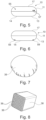
- FIG 1 shows a schematic sectional drawing of a filter device 10 not covered by the invention, which is arranged on a lid 45 of a food preparation vessel 44.
- Figure 2 shows the corresponding top view.
- the filter device 10 is shown in the manner of an exploded view above the lid 45 and the lid 45 is shown accordingly above the food preparation vessel 44.
- the filter device 10 rests flatly and circumferentially on the lid 45 with the contact surface 14 located on its underside 12.
- the lid 45 forms an opening 50 with a diameter D ⁇ 6 cm.
- the contact surface 14 rests radially circumferentially on the material 52 of the lid 45 forming the opening 50 with respect to the main flow direction 25.
- the filter device comprises an outer housing 11 made of plastic with a top side 16 and a bottom side 12.
- the outer housing 11 has a circular shape which extends rotationally symmetrically in relation to the main flow direction 25.
- the circular inlet opening 15 is arranged centrally on the bottom side 12 and
- the circular outlet opening 19 is arranged in the middle of the top. The steam generated during food preparation flows vertically upwards through the opening 50, through the inlet opening 15 into the space 20 filled with the filter material 22 inside the filter device 10 and leaves the filter device 10 vertically upwards through the outlet opening 19.
- the filter device 10 has an outer diameter of the outer housing 11 of approximately 15 cm.
- the outer housing 11 is made of hard plastic and cannot be pushed through the opening 50.
- the mentioned diameter is the largest dimension of the filter device 10.
- the filter device 10 completely covers the opening 50.
- Figure 2 the hidden edge of the opening 50 is shown in dashed lines.
- the inflow opening 15 and the outflow opening 19 also completely cover the opening 50.
- the Figures 3 and 4 show sectional views of various filter devices 10 not covered by the invention. These are designed similarly to those in the Figures 1 and 2 shown filter devices 10 and reference is therefore made to the above descriptions.
- the filter devices 10 each comprise a housing 11 in which the space 20 with the filter material 22 is arranged.
- the housing 11 is analogous to the Figures 1 and 2 rotationally symmetrical, but convexly curved on the outside.
- the inlet opening 15 arranged on the underside 12 is closed with a grid 37, namely a wire grid. This is explained with reference to Figure 9
- the chamber 20 with the filter material 22 is in Figure 3 circular cylindrical shape and runs with a straight wall between the inlet opening 15 and the outlet opening.
- the space 20 is bulbous in shape and runs with concavely curved outer walls between the inflow opening 15 and the outflow opening. In this way, the volume of the space 20 is larger and the unused volume, which is inside the filter device 10 but outside the space 20, is smaller.
- the outflow opening can basically also be arranged laterally. There can be several outflow openings, which can be arranged distributed around the circumference, for example.
- FIGS. 5 and 6 show side views of embodiments of filter devices 10 not covered by the invention.
- These have a two-part housing 11 made of plastic, which consists of a housing upper part 17 and a Housing base part 13 is assembled. These parts can be mechanically connected to and separated from each other, in particular by means of a bayonet lock. In this way, the housing 11 can be opened in order to replace the filter material.
- the filter device 10 comprises a fan 55 in its interior, which creates an air flow between the inflow opening on the underside 12 and the outflow opening on the top. This facilitates the flow of steam through the filter device 10.
- the filter device 10 has two electrical contacts 57 on the outside of the housing 11 for supplying energy to the electric motor of the fan 55.
- a battery can be arranged inside the housing for this purpose, which can be changed by opening the housing.
- Holes 59 are arranged in the housing base 13 radially outside of the inlet opening. Condensation water located in a peripheral inner region of the filter device 10, which is outside the space for receiving the filter material, can drain through these holes.
- FIG 7 shows a schematic of a filter bag 39.
- This has a circular cross-section and contains granulated activated carbon.
- the outer wall of the filter bag 39 is formed by a vapor-permeable fabric.
- the filter bag 39 is placed in the space 20, which can be e.g. in the Figures 1, 3 and 4 shown. In particular, the housing can be opened and closed to replace the filter bag 39.
- Figure 8 shows an example of a filter element 38.
- This is a porous solid body, in particular made of activated carbon, which is penetrated by a large number of channels 36. The steam can flow through these to be filtered.
- the filter element 38 can be arranged in the space in an exchangeable manner and/or can be firmly attached thereto.
- the filter housing 31 with the inner channel structure, which can be in Fig.10 shown, can be provided cost-effectively by an appropriately dimensioned filter element 38.
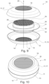
- the Figures 9 and 10 show a further embodiment of the filter device 10 not covered by the invention, wherein Figure 9 is an exploded view.
- the filter device 10 comprises a Housing 11 with an upper housing part 17 and a lower housing part 13 as well as a rotationally symmetrical filter unit 30 arranged between them.
- the upper housing part 17 can be reversibly connected to the filter unit 30 using fastening means (not shown) in the manner of a bayonet lock.
- the lower housing part 13 can be reversibly connected to the filter unit 30 using fastening means (not shown) in the manner of a bayonet lock.
- the upper housing part 17 and the lower housing part 13 are in particular designed at least substantially the same.
- the metal sieve meshes form a number of inflow openings 15.
- the metal sieve serves as a grid 37, which catches fat and oil droplets or at least partially prevents them from reaching the filter material.
- the top side 16 with the outflow opening 19 is designed accordingly.
- the housing upper part 17 and the housing lower part 13 are designed so that they can be washed and/or cleaned in the dishwasher.
- the filter unit 30 comprises a filter housing 31 which contains the filter material.
- the filter housing 31 has a circular cylindrical wall and extends along the main flow direction 25.
- the upper and lower openings of the filter housing 31 are closed with a grid having a honeycomb structure so that the filter material is held firmly. Steam can flow in and out through the openings in the grid.
- a circumferential seal 34 is arranged in the area of the upper and lower end faces of the wall, which seal separates the space 20 with the filter material from the peripheral inner area of the filter device 10 located outside the space 20.
- the upper seal presses against the upper housing part 17 and encloses the outflow opening. The same applies to the lower seal. This prevents steam from getting into the peripheral inner area.
- the filter unit 30 comprises a fastening section 32 which projects radially outward from the wall of the filter housing 31 and is designed as a circumferential disk which extends in a horizontal plane.
- the fastening section 32 is made of plastic, e.g. Plexiglas. It is arranged between the upper housing part 17 and the lower housing part 13. It is held by the outer housing 11.
- the fastening section 31 can also serve to simplify handling, for example when changing the filter unit 30.
- Figure 10 shows the filter device 10, in particular the one from Figure 9 , in the closed position.
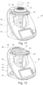
- FIG 11 shows a food processor 40 not covered by the invention for preparing a meal in a food preparation vessel 44.
- the food processor 40 comprises a heating element for heating the meal in the food preparation vessel 44 and a rotatable tool 42 for mixing or chopping the meal in the food preparation vessel 44 as well as the removable food preparation vessel 44.
- the food processor 40 further comprises the filter device 10 not covered by the invention, for example according to Figure 10 , for filtering steam 27 generated during a food preparation process from the food preparation vessel 44.
- the food preparation vessel 44 and the upper housing part 17 of the filter device 10 are shown partially transparent.
- the food processor 40 comprises a lid 45 which detachably covers the food preparation vessel 44 and has an opening with a maximum diameter of 6 cm.
- the filter device 10 is positioned on the lid 45 and completely covers the opening.
- a circumferential contact surface of the filter device 10 lies flatly and largely sealingly on the material 52 of the lid 45, so that the steam 27 which leaves the food preparation vessel 44 upwards through the opening is almost completely filtered. It flows into the filter device 10, flows through the filter unit 30 with the filter material and leaves the filter device 10 upwards through the outlet opening 19 in a purified form.
- FIG 12 shows a food processor 40 according to the invention with a suction device 48.
- the food processor 40 is designed like the one in Figure 11 shown food processor 40, but does not contain a filter device 10 positioned on the lid 45.
- the filter device 10 in the embodiment shown here is arranged inside the housing of the food processor 40. It can be designed to be replaceable and accessible from the outside so that it can be replaced when the filter material is loaded.
- the suction device 48 comprises a suction opening 49, which is arranged in the handle 46 of the food processor 40. Steam 27 that is generated is sucked in through this.
- the suction opening 49 is slot-shaped and follows the curved contour of the carrying handle 46.
- An exhaust grille protects the extraction opening 49 and forms part of the outer contour of the carrying handle 46.
- the sucked-in steam 27 is guided to the filter device 10 through an exhaust duct inside the carrying handle and the housing of the food processor 40.
- An air flow for sucking in the steam is generated by a fan which is driven by an electric motor. This can be the electric motor for driving the tool 42 or a separate electric motor.
- the steam 27 conveyed in this way flows through an inlet opening into the filter device, is filtered by the filter material in the filter device and flows out of the filter device again through an outlet opening.
- the suction device can be designed in such a way that the filtered steam 27 flows out of the outlet opening directly to the outside.
- the outlet opening of the filter device is simultaneously the air outlet 47 of the suction device.
- an exhaust air duct can be arranged between the outlet opening and the air outlet 47.
- the food processor can also comprise a device for separating water from the steam 27, which can comprise a cooling element for cooling the steam for the purpose of condensing the water contained therein.
- Filter device 10 Outer casing 11 bottom 12 Housing base 13 Contact surface 14 Inlet opening 15 Top 16 Housing top 17 Outlet opening 19 Space 20 Filter material 22 Main flow direction 25 steam 27 biggest expansion 29 Filter unit 30 Filter housing 31 Mounting section 32 poetry 34 channel 36 Grid 37 Filter element 38 Filter bags 39 Food processor 40 Tool 42 Food preparation vessel 44 Lid 45 Carrying handle 46 Air outlet 47 Extraction device 48 Extraction opening 49 opening 50 material 52 diameter D fan 55 contacts 57 Hole 59
Landscapes
- Engineering & Computer Science (AREA)
- Food Science & Technology (AREA)
- Mechanical Engineering (AREA)
- Chemical & Material Sciences (AREA)
- Chemical Kinetics & Catalysis (AREA)
- Life Sciences & Earth Sciences (AREA)
- Geology (AREA)
- Filtering Of Dispersed Particles In Gases (AREA)
- Food-Manufacturing Devices (AREA)
- Cookers (AREA)
Applications Claiming Priority (1)
| Application Number | Priority Date | Filing Date | Title |
|---|---|---|---|
| DE102020215267.5A DE102020215267A1 (de) | 2020-12-03 | 2020-12-03 | Filtervorrichtung für eine Küchenmaschine und Küchenmaschine |
Publications (3)
| Publication Number | Publication Date |
|---|---|
| EP4014822A1 EP4014822A1 (de) | 2022-06-22 |
| EP4014822B1 true EP4014822B1 (de) | 2024-05-22 |
| EP4014822C0 EP4014822C0 (de) | 2024-05-22 |
Family
ID=78592623
Family Applications (1)
| Application Number | Title | Priority Date | Filing Date |
|---|---|---|---|
| EP21207167.4A Active EP4014822B1 (de) | 2020-12-03 | 2021-11-09 | Filtervorrichtung für eine küchenmaschine und küchenmaschine |
Country Status (7)
| Country | Link |
|---|---|
| US (1) | US20220175185A1 (pl) |
| EP (1) | EP4014822B1 (pl) |
| CN (1) | CN114587151B (pl) |
| AU (1) | AU2021258030A1 (pl) |
| DE (1) | DE102020215267A1 (pl) |
| ES (1) | ES2982343T3 (pl) |
| PL (1) | PL4014822T3 (pl) |
Families Citing this family (3)
| Publication number | Priority date | Publication date | Assignee | Title |
|---|---|---|---|---|
| US11883773B2 (en) * | 2022-02-21 | 2024-01-30 | Oscar Galan | Odor filtering lid assembly |
| DE202022105659U1 (de) * | 2022-03-25 | 2022-11-14 | Wundermix Gmbh | Topfanordnung sowie Küchenmaschine |
| EP4265162A1 (de) * | 2022-04-20 | 2023-10-25 | Vorwerk & Co. Interholding GmbH | Küchenmaschine und dunstabzugsmodul |
Family Cites Families (15)
| Publication number | Priority date | Publication date | Assignee | Title |
|---|---|---|---|---|
| US1368007A (en) * | 1919-06-02 | 1921-02-08 | Badger Metal Ware Company | Frying-pan |
| US1794940A (en) * | 1929-11-11 | 1931-03-03 | Anna E Zimmermann | Absorbent lid device for frying pans |
| US1942900A (en) * | 1932-04-23 | 1934-01-09 | Robert H Peters | Deodorant attachment for cooking utensils |
| DE3479287D1 (en) | 1984-01-25 | 1989-09-14 | Itt Ind Belgium | Electrical cooking appliance including gas suction means |
| ITMI20020406U1 (it) * | 2002-08-30 | 2004-02-29 | Stefanoni Roberto | Coperchio universale per pentola assorbente e filtrante vapori ed odori |
| US20050223906A1 (en) | 2004-04-12 | 2005-10-13 | Zhaoxia Xu | Stir-frying Apparatus with Overhead Heating Device |
| FR2934140B1 (fr) * | 2008-07-25 | 2010-09-03 | Seb Sa | Couvercle d'appareil electromenager de cuisson comportant un sous-ensemble de filtration |
| CN201316179Y (zh) * | 2009-04-27 | 2009-09-30 | 钱海鹏 | 双光谱无油烟智能烹烤机 |
| JP5587243B2 (ja) * | 2011-05-16 | 2014-09-10 | 象印マホービン株式会社 | 加熱調理器 |
| US9327900B2 (en) * | 2014-09-09 | 2016-05-03 | Keurig Green Mountain, Inc. | Method and apparatus for cartridge-based carbonation of beverages |
| US10051987B2 (en) * | 2016-02-16 | 2018-08-21 | Joel Bebo | Tea and coffee brewing apparatus with telescoping filter housing |
| KR102292655B1 (ko) * | 2017-04-26 | 2021-08-23 | 지브이에스 필트레이션, 인코포레이티드 | 다중 비드 에어 필터 씰 |
| DE102017223828A1 (de) * | 2017-12-27 | 2019-06-27 | Wilhelm Bruckbauer | Dunstabzugsvorrichtung zum Abzug von Kochdünsten nach unten |
| US11013366B2 (en) | 2018-01-04 | 2021-05-25 | Tsann Kuen (Zhangzhou) Enterprise Co., Ltd. | Grill device with a fume collecting chamber |
| DE202019102320U1 (de) * | 2019-04-25 | 2019-05-23 | Warimex Waren-Import Export Handels-Gmbh | Glasdeckel für Töpfe und Pfannen |
-
2020
- 2020-12-03 DE DE102020215267.5A patent/DE102020215267A1/de active Pending
-
2021
- 2021-10-28 AU AU2021258030A patent/AU2021258030A1/en active Pending
- 2021-11-09 ES ES21207167T patent/ES2982343T3/es active Active
- 2021-11-09 PL PL21207167.4T patent/PL4014822T3/pl unknown
- 2021-11-09 EP EP21207167.4A patent/EP4014822B1/de active Active
- 2021-12-02 CN CN202111460616.3A patent/CN114587151B/zh active Active
- 2021-12-02 US US17/540,652 patent/US20220175185A1/en active Pending
Also Published As
| Publication number | Publication date |
|---|---|
| DE102020215267A1 (de) | 2022-06-09 |
| EP4014822C0 (de) | 2024-05-22 |
| CN114587151B (zh) | 2025-02-18 |
| EP4014822A1 (de) | 2022-06-22 |
| CN114587151A (zh) | 2022-06-07 |
| PL4014822T3 (pl) | 2024-09-16 |
| ES2982343T3 (es) | 2024-10-15 |
| AU2021258030A1 (en) | 2022-06-23 |
| US20220175185A1 (en) | 2022-06-09 |
Similar Documents
| Publication | Publication Date | Title |
|---|---|---|
| EP4014822B1 (de) | Filtervorrichtung für eine küchenmaschine und küchenmaschine | |
| DE10353321B4 (de) | Filtervorrichtung für eine Staubsammelvorrichtung vom Wirbelungstyp eines Staubsaugers | |
| DE10347454B4 (de) | Filteranordnung für eine Staubsammelvorrichtung vom Wirbelungstyp eines Staubsaugers | |
| DE69925157T2 (de) | Stielstaubsauger mit zyklonartiger luftströmung | |
| DE2854245C2 (de) | Staubsauger mit tonnenförmigem Sammelbehälter | |
| DE10222656B4 (de) | Zyklon-Staubsammelvorrichtung für die Verwendung in einem Staubsauger | |
| WO2019081271A1 (de) | Kombinationsgerät mit dunstabzugsvorrichtung und kochfeld | |
| DE1951306B2 (de) | Staubabscheider und -sammler an einem staubsauger | |
| EP2735354B1 (de) | Aktivkohle-Luftfilter mit konischem Innenkorb | |
| WO2018219499A1 (de) | Luftwäscher | |
| DE1628635B1 (de) | Staubsauger mit einem im unteren gehäuseteil lösbar angeordneten staubsammelkasten | |
| DE102012100050A1 (de) | Staubsammelbehälter für einen Akkutischsauger mit einem solchen Staubsammelbehälter | |
| DE2932803C2 (de) | Wirbelschichtapparatur | |
| EP3599955B1 (de) | Vorrichtung zum erhitzen und/oder garen von lebensmitteln | |
| DE2343971A1 (de) | Geraet zur fussbodenpflege | |
| EP0510056B1 (de) | Staubsauger | |
| EP1326692B1 (de) | Vorrichtung zum reinigen von flüssigkeiten | |
| EP3789681A1 (de) | Dunstabzugsvorrichtung und kombinationsgerät | |
| DE602004012047T2 (de) | Abfalltrennvorrichtung für Staubsauger | |
| DE202020005814U1 (de) | Filtervorrichtung für eine Küchenmaschine und Küchenmaschine | |
| DE3436064C2 (de) | Naß- und Trockensauger | |
| EP3764861B1 (de) | Sauggerät | |
| EP4265162A1 (de) | Küchenmaschine und dunstabzugsmodul | |
| DE68906083T2 (de) | Entlueftete tische. | |
| EP0488014A1 (de) | Schmutzsauger mit einem austauschbaren Schmutzbehälter |
Legal Events
| Date | Code | Title | Description |
|---|---|---|---|
| PUAI | Public reference made under article 153(3) epc to a published international application that has entered the european phase |
Free format text: ORIGINAL CODE: 0009012 |
|
| STAA | Information on the status of an ep patent application or granted ep patent |
Free format text: STATUS: THE APPLICATION HAS BEEN PUBLISHED |
|
| AK | Designated contracting states |
Kind code of ref document: A1 Designated state(s): AL AT BE BG CH CY CZ DE DK EE ES FI FR GB GR HR HU IE IS IT LI LT LU LV MC MK MT NL NO PL PT RO RS SE SI SK SM TR |
|
| STAA | Information on the status of an ep patent application or granted ep patent |
Free format text: STATUS: REQUEST FOR EXAMINATION WAS MADE |
|
| 17P | Request for examination filed |
Effective date: 20220909 |
|
| RBV | Designated contracting states (corrected) |
Designated state(s): AL AT BE BG CH CY CZ DE DK EE ES FI FR GB GR HR HU IE IS IT LI LT LU LV MC MK MT NL NO PL PT RO RS SE SI SK SM TR |
|
| GRAP | Despatch of communication of intention to grant a patent |
Free format text: ORIGINAL CODE: EPIDOSNIGR1 |
|
| STAA | Information on the status of an ep patent application or granted ep patent |
Free format text: STATUS: GRANT OF PATENT IS INTENDED |
|
| RIC1 | Information provided on ipc code assigned before grant |
Ipc: A47J 36/38 20060101ALI20231206BHEP Ipc: A47J 43/07 20060101AFI20231206BHEP |
|
| INTG | Intention to grant announced |
Effective date: 20240105 |
|
| GRAS | Grant fee paid |
Free format text: ORIGINAL CODE: EPIDOSNIGR3 |
|
| GRAA | (expected) grant |
Free format text: ORIGINAL CODE: 0009210 |
|
| STAA | Information on the status of an ep patent application or granted ep patent |
Free format text: STATUS: THE PATENT HAS BEEN GRANTED |
|
| AK | Designated contracting states |
Kind code of ref document: B1 Designated state(s): AL AT BE BG CH CY CZ DE DK EE ES FI FR GB GR HR HU IE IS IT LI LT LU LV MC MK MT NL NO PL PT RO RS SE SI SK SM TR |
|
| REG | Reference to a national code |
Ref country code: GB Ref legal event code: FG4D Free format text: NOT ENGLISH |
|
| REG | Reference to a national code |
Ref country code: CH Ref legal event code: EP |
|
| REG | Reference to a national code |
Ref country code: DE Ref legal event code: R096 Ref document number: 502021003783 Country of ref document: DE |
|
| REG | Reference to a national code |
Ref country code: IE Ref legal event code: FG4D Free format text: LANGUAGE OF EP DOCUMENT: GERMAN |
|
| U01 | Request for unitary effect filed |
Effective date: 20240522 |
|
| U07 | Unitary effect registered |
Designated state(s): AT BE BG DE DK EE FI FR IT LT LU LV MT NL PT SE SI Effective date: 20240529 |
|
| PG25 | Lapsed in a contracting state [announced via postgrant information from national office to epo] |
Ref country code: IS Free format text: LAPSE BECAUSE OF FAILURE TO SUBMIT A TRANSLATION OF THE DESCRIPTION OR TO PAY THE FEE WITHIN THE PRESCRIBED TIME-LIMIT Effective date: 20240922 |
|
| PG25 | Lapsed in a contracting state [announced via postgrant information from national office to epo] |
Ref country code: HR Free format text: LAPSE BECAUSE OF FAILURE TO SUBMIT A TRANSLATION OF THE DESCRIPTION OR TO PAY THE FEE WITHIN THE PRESCRIBED TIME-LIMIT Effective date: 20240522 |
|
| PG25 | Lapsed in a contracting state [announced via postgrant information from national office to epo] |
Ref country code: GR Free format text: LAPSE BECAUSE OF FAILURE TO SUBMIT A TRANSLATION OF THE DESCRIPTION OR TO PAY THE FEE WITHIN THE PRESCRIBED TIME-LIMIT Effective date: 20240823 |
|
| REG | Reference to a national code |
Ref country code: ES Ref legal event code: FG2A Ref document number: 2982343 Country of ref document: ES Kind code of ref document: T3 Effective date: 20241015 |
|
| PG25 | Lapsed in a contracting state [announced via postgrant information from national office to epo] |
Ref country code: NO Free format text: LAPSE BECAUSE OF FAILURE TO SUBMIT A TRANSLATION OF THE DESCRIPTION OR TO PAY THE FEE WITHIN THE PRESCRIBED TIME-LIMIT Effective date: 20240822 Ref country code: IS Free format text: LAPSE BECAUSE OF FAILURE TO SUBMIT A TRANSLATION OF THE DESCRIPTION OR TO PAY THE FEE WITHIN THE PRESCRIBED TIME-LIMIT Effective date: 20240922 Ref country code: HR Free format text: LAPSE BECAUSE OF FAILURE TO SUBMIT A TRANSLATION OF THE DESCRIPTION OR TO PAY THE FEE WITHIN THE PRESCRIBED TIME-LIMIT Effective date: 20240522 Ref country code: GR Free format text: LAPSE BECAUSE OF FAILURE TO SUBMIT A TRANSLATION OF THE DESCRIPTION OR TO PAY THE FEE WITHIN THE PRESCRIBED TIME-LIMIT Effective date: 20240823 Ref country code: RS Free format text: LAPSE BECAUSE OF FAILURE TO SUBMIT A TRANSLATION OF THE DESCRIPTION OR TO PAY THE FEE WITHIN THE PRESCRIBED TIME-LIMIT Effective date: 20240822 |
|
| U20 | Renewal fee for the european patent with unitary effect paid |
Year of fee payment: 4 Effective date: 20241125 |
|
| PGFP | Annual fee paid to national office [announced via postgrant information from national office to epo] |
Ref country code: PL Payment date: 20241025 Year of fee payment: 4 |
|
| PG25 | Lapsed in a contracting state [announced via postgrant information from national office to epo] |
Ref country code: CZ Free format text: LAPSE BECAUSE OF FAILURE TO SUBMIT A TRANSLATION OF THE DESCRIPTION OR TO PAY THE FEE WITHIN THE PRESCRIBED TIME-LIMIT Effective date: 20240522 |
|
| PG25 | Lapsed in a contracting state [announced via postgrant information from national office to epo] |
Ref country code: SK Free format text: LAPSE BECAUSE OF FAILURE TO SUBMIT A TRANSLATION OF THE DESCRIPTION OR TO PAY THE FEE WITHIN THE PRESCRIBED TIME-LIMIT Effective date: 20240522 Ref country code: RO Free format text: LAPSE BECAUSE OF FAILURE TO SUBMIT A TRANSLATION OF THE DESCRIPTION OR TO PAY THE FEE WITHIN THE PRESCRIBED TIME-LIMIT Effective date: 20240522 |
|
| PGFP | Annual fee paid to national office [announced via postgrant information from national office to epo] |
Ref country code: ES Payment date: 20241213 Year of fee payment: 4 |
|
| PG25 | Lapsed in a contracting state [announced via postgrant information from national office to epo] |
Ref country code: SK Free format text: LAPSE BECAUSE OF FAILURE TO SUBMIT A TRANSLATION OF THE DESCRIPTION OR TO PAY THE FEE WITHIN THE PRESCRIBED TIME-LIMIT Effective date: 20240522 Ref country code: RO Free format text: LAPSE BECAUSE OF FAILURE TO SUBMIT A TRANSLATION OF THE DESCRIPTION OR TO PAY THE FEE WITHIN THE PRESCRIBED TIME-LIMIT Effective date: 20240522 Ref country code: CZ Free format text: LAPSE BECAUSE OF FAILURE TO SUBMIT A TRANSLATION OF THE DESCRIPTION OR TO PAY THE FEE WITHIN THE PRESCRIBED TIME-LIMIT Effective date: 20240522 |
|
| PGFP | Annual fee paid to national office [announced via postgrant information from national office to epo] |
Ref country code: CH Payment date: 20241201 Year of fee payment: 4 |
|
| REG | Reference to a national code |
Ref country code: DE Ref legal event code: R097 Ref document number: 502021003783 Country of ref document: DE |
|
| PLBE | No opposition filed within time limit |
Free format text: ORIGINAL CODE: 0009261 |
|
| STAA | Information on the status of an ep patent application or granted ep patent |
Free format text: STATUS: NO OPPOSITION FILED WITHIN TIME LIMIT |
|
| 26N | No opposition filed |
Effective date: 20250225 |
|
| PG25 | Lapsed in a contracting state [announced via postgrant information from national office to epo] |
Ref country code: MC Free format text: LAPSE BECAUSE OF FAILURE TO SUBMIT A TRANSLATION OF THE DESCRIPTION OR TO PAY THE FEE WITHIN THE PRESCRIBED TIME-LIMIT Effective date: 20240522 |
|
| PG25 | Lapsed in a contracting state [announced via postgrant information from national office to epo] |
Ref country code: IE Free format text: LAPSE BECAUSE OF NON-PAYMENT OF DUE FEES Effective date: 20241109 |
|
| REG | Reference to a national code |
Ref country code: CH Ref legal event code: U11 Free format text: ST27 STATUS EVENT CODE: U-0-0-U10-U11 (AS PROVIDED BY THE NATIONAL OFFICE) Effective date: 20251201 |