EP4013655B1 - Chassis for a rail vehicle - Google Patents
Chassis for a rail vehicle Download PDFInfo
- Publication number
- EP4013655B1 EP4013655B1 EP20789489.0A EP20789489A EP4013655B1 EP 4013655 B1 EP4013655 B1 EP 4013655B1 EP 20789489 A EP20789489 A EP 20789489A EP 4013655 B1 EP4013655 B1 EP 4013655B1
- Authority
- EP
- European Patent Office
- Prior art keywords
- spring
- chassis
- bearing apparatus
- drive unit
- bearing
- Prior art date
- Legal status (The legal status is an assumption and is not a legal conclusion. Google has not performed a legal analysis and makes no representation as to the accuracy of the status listed.)
- Active
Links
- 230000008878 coupling Effects 0.000 claims description 89
- 238000010168 coupling process Methods 0.000 claims description 89
- 238000005859 coupling reaction Methods 0.000 claims description 89
- 230000005540 biological transmission Effects 0.000 description 11
- 230000006835 compression Effects 0.000 description 5
- 238000007906 compression Methods 0.000 description 5
- 238000003466 welding Methods 0.000 description 5
- 238000005516 engineering process Methods 0.000 description 4
- 239000000725 suspension Substances 0.000 description 4
- 239000000969 carrier Substances 0.000 description 3
- 238000006243 chemical reaction Methods 0.000 description 3
- 229910052751 metal Inorganic materials 0.000 description 3
- 238000010276 construction Methods 0.000 description 2
- 238000013016 damping Methods 0.000 description 2
- 230000002349 favourable effect Effects 0.000 description 2
- 238000009434 installation Methods 0.000 description 2
- 239000002184 metal Substances 0.000 description 2
- 230000001681 protective effect Effects 0.000 description 2
- 229910000831 Steel Inorganic materials 0.000 description 1
- 230000001133 acceleration Effects 0.000 description 1
- 230000003044 adaptive effect Effects 0.000 description 1
- 238000013459 approach Methods 0.000 description 1
- 230000007613 environmental effect Effects 0.000 description 1
- 238000000034 method Methods 0.000 description 1
- 230000036316 preload Effects 0.000 description 1
- 239000007787 solid Substances 0.000 description 1
- 239000010959 steel Substances 0.000 description 1
Images
Classifications
-
- B—PERFORMING OPERATIONS; TRANSPORTING
- B61—RAILWAYS
- B61C—LOCOMOTIVES; MOTOR RAILCARS
- B61C9/00—Locomotives or motor railcars characterised by the type of transmission system used; Transmission systems specially adapted for locomotives or motor railcars
- B61C9/38—Transmission systems in or for locomotives or motor railcars with electric motor propulsion
- B61C9/48—Transmission systems in or for locomotives or motor railcars with electric motor propulsion with motors supported on vehicle frames and driving axles, e.g. axle or nose suspension
- B61C9/50—Transmission systems in or for locomotives or motor railcars with electric motor propulsion with motors supported on vehicle frames and driving axles, e.g. axle or nose suspension in bogies
-
- B—PERFORMING OPERATIONS; TRANSPORTING
- B61—RAILWAYS
- B61F—RAIL VEHICLE SUSPENSIONS, e.g. UNDERFRAMES, BOGIES OR ARRANGEMENTS OF WHEEL AXLES; RAIL VEHICLES FOR USE ON TRACKS OF DIFFERENT WIDTH; PREVENTING DERAILING OF RAIL VEHICLES; WHEEL GUARDS, OBSTRUCTION REMOVERS OR THE LIKE FOR RAIL VEHICLES
- B61F3/00—Types of bogies
- B61F3/02—Types of bogies with more than one axle
- B61F3/04—Types of bogies with more than one axle with driven axles or wheels
-
- B—PERFORMING OPERATIONS; TRANSPORTING
- B61—RAILWAYS
- B61F—RAIL VEHICLE SUSPENSIONS, e.g. UNDERFRAMES, BOGIES OR ARRANGEMENTS OF WHEEL AXLES; RAIL VEHICLES FOR USE ON TRACKS OF DIFFERENT WIDTH; PREVENTING DERAILING OF RAIL VEHICLES; WHEEL GUARDS, OBSTRUCTION REMOVERS OR THE LIKE FOR RAIL VEHICLES
- B61F5/00—Constructional details of bogies; Connections between bogies and vehicle underframes; Arrangements or devices for adjusting or allowing self-adjustment of wheel axles or bogies when rounding curves
- B61F5/50—Other details
- B61F5/52—Bogie frames
Definitions
- the invention relates to a chassis of a rail vehicle, with at least one chassis frame to which at least a first wheel set and a second wheel set are coupled and to which at least a first drive unit and a second drive unit are connected.
- Tie rods or tie/push rods as longitudinal carriers can hardly be connected to end supports of chassis frames of rail vehicle chassis, since on the one hand the lengths of the tie rods or tie/push rods would be too short and consequently angles would become too large due to turning and pitching of the chassis and on the other hand the free space to guide the tie rods or tie/push rods under a drive unit to cross members of the chassis frame is only available to a limited extent due to limited installation space budgets.
- Such longitudinal carriers have the disadvantage that they have to be made solid and that a strong weight shift is caused due to relatively high force introduction points between the car bodies and the chassis.
- different load conditions on the wheel sets of the chassis must be compensated electrically, for example via a drive control, or by means of actuators.
- weight shifts are compensated electrically, motors, power converters, Wiring, wheel axles, etc. oversized accordingly
- the state of the art for example, is the CN 105 292 139 A which shows a chassis of a rail vehicle.
- WO 2015/117678 A1 shows a rail vehicle with a longitudinal carriage of a car body by a chassis via a pivot pin.
- the WO 2011/141510 A1 a drive of a rail vehicle.
- the drive is connected via a cardan to a chassis or a car body of the rail vehicle on the one hand and to a wheel set of the chassis on the other. Due to its cardan bearing, the drive is rotatable with respect to two axes of rotation that are aligned perpendicularly to each other, which in turn are aligned perpendicularly to a rotor axis of rotation of the drive.
- the EP 3 272 614 A1 a chassis for a rail vehicle is disclosed, the wheel sets of which have a smooth steering behavior, which is achieved due to ball-joint connections of a drive of the rail vehicle with a chassis frame.
- the last two approaches in their known forms have the disadvantage of excessive mobility of the drives relative to the chassis frames, wheel sets and/or car bodies of the rail vehicles for certain categories of rail vehicles or chassis and/or for certain driving speed ranges.
- a chassis for a rail vehicle has a first drive unit, which is connected to a car body via a steering rod.
- the first drive unit is coupled to a second drive unit of the chassis.
- the first The drive unit and the second drive unit are connected to a chassis frame via pendulums.
- the invention is based on the object of specifying a chassis that is further developed compared to the prior art, the longitudinal drive and the drive bearing of which enable acceleration and deceleration with little weight shift.
- the spring stiffness of one or more springs of the first coupling rod can be dimensioned to suit the required tractive force ranges and the required compression and rebound resistances of the chassis.
- a drive bearing is achieved that is adapted to the longitudinal drive via the first coupling rod. Movements of the first drive unit that disrupt the longitudinal drive (i.e. rotational or tilting movements about a chassis longitudinal axis and about the chassis transverse axis) are avoided. Only slight rotational movements about the drive vertical axis are possible, which can move with the first drive unit in the direction of the chassis transverse axis due to a translational mobility of the first drive unit in the direction of the chassis transverse axis.
- the first drive unit acts as a damper with respect to vibrations transverse to a direction of travel of the rail vehicle.
- a favorable embodiment is obtained if first stiffnesses of the first bearing device and the second bearing device in a plane formed by a chassis longitudinal axis and a chassis vertical axis and second stiffnesses of the first bearing device and the second bearing device in the direction of the chassis transverse axis are adjustable independently of one another.
- a particularly strong spread of stiffnesses of the first bearing device and the second bearing device and thus a high resistance to rotational or tilting movements of the first drive unit about the chassis longitudinal axis and about the chassis transverse axis as well as a smooth translational mobility of the first drive unit in the direction of the chassis transverse axis are achieved if a stiffness ratio between the first stiffness and the second stiffness of at least 1 to 40 is set.
- first coupling rod is connected in an articulated manner to the at least first drive unit via the second bearing device, wherein the first coupling rod is connected to the second bearing device via a joint which is arranged closer to the second cross member than to the first cross member.
- the first coupling rod can be designed in a simple geometry because guiding the first coupling rod to the first cross member is avoided.
- a favorable solution is achieved if the first bearing device is arranged to protrude into at least one support recess of the first cross member.
- This measure provides a certain degree of protection of the first storage device from environmental influences as well as a space-saving arrangement.
- At least one first spring device of the first bearing device is connected to the first cross member, the first spring longitudinal axis of which is aligned parallel to a chassis vertical axis.
- This measure contributes to a stiff characteristic of the drive bearing in the direction of the chassis vertical axis as well as to a soft characteristic in the direction of the chassis transverse axis.
- An advantageous embodiment is further obtained if a second spring device of the second bearing device, whose second spring longitudinal axis is aligned parallel to a chassis longitudinal axis, a third spring device of the second bearing device, whose third spring longitudinal axis is aligned parallel to a chassis vertical axis, and a fourth spring device of the second bearing device, whose fourth spring longitudinal axis is aligned parallel to the chassis vertical axis, are connected to the second cross member.
- the second bearing device has a spring recess, wherein the second spring device is arranged to protrude into the spring recess.
- the spring recess results in a reduction in the mass of the second bearing device, and on the other hand, the spring recess functions as an assembly opening for the second spring device, thereby simplifying the assembly and disassembly of the second spring device.
- the second bearing device has a through-hole through which a wheel set shaft of at least the first wheel set is guided, wherein the through-hole is closed at the bottom by means of a closure piece detachably connected to the second bearing device.
- This measure also implements a lightweight construction principle with regard to the second bearing device. At the same time, thanks to the locking piece, it is possible to assemble and disassemble the first wheel set with the second bearing device installed.
- the second drive unit is connected to the first cross member via a third bearing device, wherein the first bearing device and the third bearing device are arranged in a fork-like manner projecting into one another.
- This measure ensures that the first bearing device and the third bearing device are connected to the first cross member in a space-saving manner, and that the installation space available on the first cross member is used efficiently.
- An adaptive suspension behavior of the longitudinal drive is made possible if a coupling spring device is connected to the first coupling rod, via which the first coupling rod can be coupled to the car body, whereby the Coupling spring device has at least a first spring stiffness and a second spring stiffness, which are designed differently from one another.
- the first spring stiffness can, for example, be dimensioned with regard to the high tensile forces of the rail vehicle, the second spring stiffness with regard to low tensile forces as well as low turning and compression or rebound resistance. This means that suitable spring forces are available for different tensile force ranges.
- a second coupling rod is connected in an articulated manner to the second drive unit and is designed to be resiliently coupled to the car body of the rail vehicle.
- first coupling rod and the second coupling rod distributes loads between the first coupling rod and the second coupling rod.
- first coupling rod or the second coupling rod is subjected to tensile loads. Compressive loads on the first coupling rod and the second coupling rod are avoided.
- the first coupling rod and the second coupling rod can be designed as pure tension rods, i.e. they do not have to be designed as tension/compression rods.
- a coupling of the first drive unit and the second drive unit to one another is achieved if a horizontally arranged pendulum is provided between the at least first drive unit and the second drive unit.
- This measure results in a distribution of reaction forces from the first drive unit and the second drive units to the drive bearings of the first drive unit and the second drive unit.
- the drive bearings and the longitudinal carriers are partially relieved.
- reaction forces in the direction of the chassis' longitudinal axis a mutual cancellation of the reaction forces is achieved.
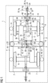
- Fig.1 shows a chassis and a car body 1 of a rail vehicle in plan view.
- the chassis has a chassis frame 2, which comprises a first longitudinal member 3, a second longitudinal member 4, a first cross member 5, a second cross member 6 and a third cross member 7.
- the first cross member 5 is designed as a central cross connector of the chassis
- the second cross member 6 and the third cross member 7 are designed as head members of the chassis.
- a first wheel set 8 and a second wheel set 9 are coupled to the chassis frame 2.
- the first wheel set 8 has a first wheel 10, a second wheel 11 and a wheel set shaft 12.
- the first wheelset 8 is connected to a first wheelset bearing, a first wheelset bearing housing, a first wheelset guiding device, which is Fig.1 are not visible, as well as a first primary spring 13 with the first longitudinal member 3 and a second wheelset bearing, a second wheelset bearing housing, a second wheelset guide device, which in Fig.1 are not visible, and via a second primary spring 14 to the second longitudinal member 4.
- the second wheel set 9 is designed in the same way as the first wheel set 8 with regard to its construction and its connection technology to the chassis frame 2.
- the car body 1 is arranged above the chassis.
- a first secondary spring 15 and a second secondary spring 16 are provided between the first cross member 5 and an underside of the car body 1.
- a first drive unit 17 and a second drive unit 18 are mounted in the chassis in a transversely elastic manner, ie in a vibration-damping manner with respect to movements in the direction of a chassis transverse axis 19.
- the first drive unit 17 is connected to the first cross member 5 via a first bearing device 20 and to the second cross member 6 via a second bearing device 21.
- the second drive unit 18 is coupled to the first cross member 5 and to the third cross member 7 via two further bearing devices.
- the first bearing device 20, the second bearing device 21 and the two further bearing devices are aligned parallel to a chassis longitudinal axis 23.
- a first coupling rod 24 is arranged between the first drive unit 17 and the underside of the car body 1, and a second coupling rod 25 is arranged between the second drive unit 18 and the underside of the car body 1.
- the first coupling rod 24 is connected in an articulated manner to the first drive unit 17 via the second bearing device 21, wherein a joint 26 is provided between the first coupling rod 24.
- the joint 26 is arranged closer to the second cross member 6 than to the first cross member 5.
- the joint 26 has a Fig.2 shown joint axis 27, which consists of a parallel to a Fig.1 projecting vertical chassis axis 28 is aligned so as to be rotated about a line parallel to the chassis transverse axis 19.
- the first coupling rod 24 is rotatable about this joint axis 27.
- a coupling spring device 29 is connected to the first coupling rod 24, via which the first coupling rod 24 is coupled to the car body 1.
- the coupling spring device 29 has a first coupling spring element 30 with a first spring stiffness k 1 , a second coupling spring element 31 with a second spring stiffness k 2 and a third coupling spring element 32 with a third spring stiffness k 3 , wherein the first spring stiffness k 1 , the second spring stiffness k 2 and the third spring stiffness k 3 are designed differently from one another.
- the first coupling spring element 30 and the second coupling spring element 31 are designed as rubber-metal layered springs, the third coupling spring element 32 as a metallic coil spring.
- the third coupling spring element 32 is connected to a welding bracket 33 of the car body 1, whereby the first coupling rod 24 is coupled to the car body 1.
- the coupling spring device 29 is clamped between a spring carrier 34 of the first coupling rod 24 and the welding bracket 33 under a pre-tension.
- the first spring stiffness k 1 is greater than the second spring stiffness k 2
- the second spring stiffness k 2 is greater than the third spring stiffness k 3 .
- the first spring stiffness k 1 is 37 kN/mm
- the first coupling spring element 30 allows a maximum spring travel of 12 mm.
- the second spring stiffness k 2 is 6 kN/mm
- the second coupling spring element 31 allows a maximum deflection of 7 mm.
- the third spring stiffness k 3 is 0.2 kN/mm.
- the third coupling spring element 32 is preloaded by 25 mm and can be deflected by a maximum of 3 mm.
- the softest, third coupling spring element 32 is initially engaged as the first spring stage when the tensile forces are low. Due to its preload, the coupling spring device 29 cannot come loose during relative movements between the car body 1 and the chassis in the direction of the chassis longitudinal axis 23, i.e. it remains clamped between the spring carrier 34 and the welding bracket 33. Due to the low third spring stiffness k 3 , the welding bracket 33 and the chassis frame 2 are only slightly loaded when the third coupling spring element 32 engages.
- the third coupling spring element 32 locks and the second coupling spring element 31 takes over a suspension function as a harder, second spring stage. This results in a transfer of medium-sized tensile forces between the car body 1 and the chassis.
- the second coupling spring element 31 is soft designed sufficiently so that turning movements of the chassis when cornering as well as compression and rebound movements of the chassis are not influenced and a largely jerk-free start is possible.
- the second coupling rod 25 is designed in the same way as the first coupling rod 24 with regard to its structural and connection properties.
- first coupling rod 24 and the second coupling rod 25 are designed as tension rods.
- the first drive unit 17 is further connected to the first wheel set 8 via a coupling 35, which is designed as a curved tooth coupling, and a gear 36, so that it can move in the direction of the chassis transverse axis 19.
- the coupling 35 is arranged between a Fig.1 invisible drive shaft of the first drive unit 17 and a Fig.1 also not visible, the transmission shaft of the transmission 36 is provided.
- the transmission shaft is in turn coupled to the wheel set shaft 12.
- a protective tube 37 is provided, which has a flange-like extension section 38 towards the second wheel 11.
- a Fig.1 A distance not shown is provided in order to be able to connect, for example, a wheel brake disc to the second wheel 11.
- the first drive unit 17 is connected to the first cross member 5 via the first bearing device 20 in a resilient manner and movably in the direction of the chassis transverse axis 19 and to the second cross member 6 via the second bearing device 21 in a resilient manner and movably in the direction of the chassis transverse axis 19.
- the first drive unit 17 is mounted for limited rotation about a drive vertical axis 39, which is displaceable in the direction of the chassis transverse axis 19.
- the first bearing device 20 has a first bearing carrier 40 and a second bearing carrier 41, which are screwed to the first drive unit 17 at a distance from one another.
- the first bearing carrier 40 and the second bearing carrier 41 are arranged in support recesses of the first cross member 5, wherein a support recess 66 in Fig.3 is shown.
- the first bearing device 20 has a first spring device 42, which in turn comprises a first spring arrangement 46 and a second spring arrangement 47.
- the first spring arrangement 46 is provided between the first cross member 5 and the first bearing carrier 40, the second spring arrangement 47 between the first cross member 5 and the second bearing carrier 41.
- the first spring assembly 46 comprises a first layer spring 52 and a Fig.3 visible second layer spring 53.
- the second spring arrangement 47 corresponds to the first spring arrangement 46 with regard to its structural properties and its orientation.
- the first spring arrangement 46 and the second spring arrangement 47 are arranged within the support recesses of the first cross member 5.
- the second bearing device 21 is designed as a lightweight support and is screwed to the first drive unit 17.
- the second cross member 6 With the second cross member 6 are a second spring device 43, the Fig.2 shown second spring longitudinal axis 49 is aligned parallel to the chassis longitudinal axis 23, a third spring device 44, the Fig.1 projecting third spring longitudinal axis 50 is aligned parallel to the chassis vertical axis 28, and a fourth spring device 45, the Fig.1 projecting appearing fourth spring longitudinal axis 51 is aligned parallel to the chassis vertical axis 28.
- the second spring device 43, the third spring device 44 and the fourth spring device 45 are parts of the second bearing device 21.
- the second spring device 43 is arranged centrally between the third spring device 44 and the fourth spring device 45 and offset relative to the third spring device 44 and the fourth spring device 45 in the direction of the chassis longitudinal axis 23.
- the second spring device 43 is provided in or connected to a first spring cup 58, the third spring device 44 in a second spring cup 59 and the fourth spring device 45 in a third spring cup 60.
- the first Spring cup 58, the second spring cup 59 and the third spring cup 60 are screwed to the second cross member 6.
- the second spring device 43 comprises a third layer spring 54 and a fourth layer spring 55, which are separated from one another by a flat, handle-shaped section of the second bearing device 21.
- the third layer spring 54 is connected to the first spring cup 58, the fourth layer spring 55 to the second cross member 6.
- the flat, handle-shaped section of the second bearing device 21 is arranged between the third layer spring 54 and the fourth layer spring 55.
- the third spring device 44 and the fourth spring device 45 are designed in the same way as the second spring device 43 with regard to their structural properties, but are rotated by 90° relative to the second spring device 43.
- the second spring device 43 is provided in the area of a spring recess 61 of the second bearing device 21, wherein the second spring device 43 is arranged so as to protrude into the spring recess 61.
- the flat, handle-shaped section of the second bearing device 21 is provided, which the third layer spring 54 and the fourth layer spring 55 contact.
- the third layer spring 54 is provided inside the spring recess 61, the fourth layer spring 55 outside the spring recess 61.
- a first overall stiffness of the first bearing device 20 and the second bearing device 21 in a plane formed by the chassis longitudinal axis 23 and the chassis vertical axis 28 and a second overall stiffness of the first bearing device 20 and the second bearing device 21 in the direction of the chassis transverse axis 19 can be adjusted precisely and independently of one another.
- the first total stiffness of the first bearing device 20 and the second bearing device 21 is greater than the second total stiffness of the first bearing device 20 and the second bearing device 21.
- a stiffness ratio of approximately 1 to 50 is set between the first total stiffness and the second total stiffness.
- the second bearing device 21 has a through-hole 62 through which the wheel set shaft 12 of the first wheel set 8 is guided.
- the through-hole 62 is closed off downwards by means of a detachably connected to the second bearing device 21, in Fig. 2 visible closure piece 63.
- the second drive unit 18 is designed in the same way as the first drive unit 17 and its connection with the first cross member 5, the second cross member 6 and the first wheel set 8.
- the second drive unit 18 is connected to the first cross member 5 via a third bearing device 22 which, like the first bearing device 20, comprises two bearing supports to which spring arrangements are connected.
- the first bearing carrier 40 with the first spring arrangement 46 and the second bearing carrier 41 with the second spring arrangement 47 of the first bearing device 20 on the one hand and the Bearing carrier and the spring arrangements of the third bearing device 22, on the other hand, are arranged in a fork-like manner projecting into one another.
- a horizontally arranged pendulum 64 is provided, which is articulatedly coupled to the first drive unit 17 on the one hand and the second drive unit 18 on the other hand.
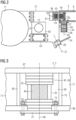
- Fig. 2 is a side elevation of a section of that exemplary embodiment of a running gear of a rail vehicle according to the invention, which is also shown in Fig.1 shown.
- a first drive unit 17 of the chassis is connected via a first bearing device 20 to a first spring device 42 comprising a first spring arrangement 46 with a first layered spring 52 and a second layered spring 53 as well as a second spring arrangement 47 designed identically to the first spring arrangement 46, which in Fig.1 or in Fig.3 shown, with a in Fig.1 and Fig.3 shown first cross member 5 of a chassis frame 2.
- first drive unit 17 is connected to a second bearing device 21, which has a second spring device 43, a third spring device 44 and a Fig.1 visible fourth spring device 45, coupled to a second cross member 6 of the chassis frame 2 designed as a head support.
- the second bearing device 21 is designed as a lightweight steel support, screwed to the first drive unit 17 and has a through-hole 62 and a spring recess 61.
- a wheelset shaft 12 of a first wheelset 8 of the chassis is passed through the through-hole 62.
- the through-hole 62 is closed at the bottom by means of a closure piece 63 which is screwed to the second bearing device 21 and is thus detachably connected.
- the first wheel set 8 can be threaded downwards out of the through-hole 62 or threaded upwards into the through-hole 62 for disassembly or assembly.
- the second bearing device 21 has a flat, handle-shaped section.
- a third layer spring 54 and a fourth layer spring 55 of the second spring device 43 contact the flat, handle-shaped section.
- the third layer spring 54 is provided with a Fig.2
- the fourth layer spring 55 is connected laterally to a detachable insert 65 of the second cross member 6.
- the third layer spring 54 is arranged within the spring recess 61.
- the first spring cup 58 is screwed laterally to the second cross member 6, enclosing the second bearing device 21 in the area of the spring recess 61.
- the insert 65 which is also screwed laterally to the second cross member 6, closes a mounting opening for the second spring device 43.
- the fourth layer spring 55 is arranged between the insert 65 and the flat, handle-shaped portion of the second bearing device 21.
- the third spring device 44 has a third spring longitudinal axis 50 which is parallel to a Fig.1 shown chassis vertical axis 28.
- a fifth layer spring 56 and a sixth layer spring 57 are arranged in a second spring cup 59, which is screwed to an underside of the second cross member 6.
- the fifth layer spring 56 is connected to the second spring cup 59 and a tab of the second bearing device 21, the sixth layer spring 57 with the tab and the underside of the second cross member 6.
- the tab of the second bearing device 21 is arranged between the fifth layer spring 56 and the sixth layer spring 57.
- the fourth spring device 45 and a Fig.1 The third spring cup 60 shown is designed in the same way as the third spring device 44 and the second spring cup 59 with regard to its structural properties and its connection technology with the second cross member 6.
- the second bearing device 21 is connected via a joint 26 to a Fig.2 shown in detail first coupling rod 24, which in turn is connected to a Fig.1 shown car body 1 of the rail vehicle.
- the joint 26 is designed as a swivel joint and has a joint axis 27 which is inclined relative to the chassis vertical axis 28, parallel to a plane formed by the chassis longitudinal axis 23 and the chassis vertical axis 28.
- the first coupling rod 24 therefore runs from the second bearing device 21 upwards to the car body 1 and is mounted on the second bearing device 21 so as to be rotatable about the joint axis 27.
- Fig.3 is a section of a first cross member 5 of a chassis frame 2, which is part of an exemplary embodiment of a Fig.1 shown, the running gear of a rail vehicle according to the invention is disclosed as a side view.
- the first cross member 5 has a support recess 66 which is formed from a first belt 67 designed as an upper belt, a second belt 68 designed as a lower belt and from a first side wall 69 and a second side wall 70 of the first cross member 5.
- the first side wall 69 and the second side wall 70 are welded to the first belt 67, the second belt 68 and to a web 71 of the first cross member 5.
- the web 71 is interrupted in the area of the support recess 66.
- the first layer spring 52 and the second layer spring 53 are designed as rubber-metal layer springs.
- the first layer spring 52 is connected to the first belt 67, the second layer spring 53 to the second belt 68.
- the first spring device 42 is part of the first bearing device 20 and has a first spring longitudinal axis 48.
- the first cross member 5 has a cylindrical opening in the region of the carrier recess 66, which is closed by means of a cover 72.
- the opening is provided in the second strap 68, extends in the vertical direction and expands the carrier recess 66 downwards and forwards.
- the second layer spring 53 is arranged to protrude into the opening and to contact the cover 72.
- the cover 72 is screwed to the second belt 68.
- annular stop 73 made of rubber is provided, which surrounds the second layer spring 53 and is provided with screws for connecting the cover 72 to the second belt 68. This limits lateral deflections of the first bearing carrier 40.
- second bearing carrier 41 of the first bearing device 20 also in Fig.1
- the second spring arrangement 47 of the first spring device 42 shown is designed in the same way as the first spring arrangement 46 with regard to its structural properties and its connection technology with the first cross member 5.
Landscapes
- Engineering & Computer Science (AREA)
- Mechanical Engineering (AREA)
- Chemical & Material Sciences (AREA)
- Combustion & Propulsion (AREA)
- Transportation (AREA)
- Vehicle Body Suspensions (AREA)
- Arrangement Or Mounting Of Propulsion Units For Vehicles (AREA)
Description
Die Erfindung betrifft ein Fahrwerk eines Schienenfahrzeugs, mit zumindest einem Fahrwerksrahmen, an den zumindest ein erster Radsatz und ein zweiter Radsatz gekoppelt sind und mit dem zumindest eine erste Antriebseinheit und eine zweite Antriebseinheit verbunden sind.The invention relates to a chassis of a rail vehicle, with at least one chassis frame to which at least a first wheel set and a second wheel set are coupled and to which at least a first drive unit and a second drive unit are connected.
Zugstangen bzw. Zug-/Druckstangen als Längsmitnahmen können kaum mit Kopfträgern von Fahrwerksrahmen von Fahrwerken von Schienenfahrzeugen verbunden werden, da einerseits Längen der Zugstangen bzw. der Zug-/Druckstangen zu gering und folglich Winkel durch Ausdreh- und Nickvorgänge der Fahrwerke zu groß werden würden und andererseits Freiräume, um die Zugstangen bzw. die Zug-/Druckstangen unter einer Antriebseinheit zu Querträgern der Fahrwerksrahmen zu führen, aufgrund begrenzter Bauraumbudgets nur in geringem Ausmaß verfügbar sind.Tie rods or tie/push rods as longitudinal carriers can hardly be connected to end supports of chassis frames of rail vehicle chassis, since on the one hand the lengths of the tie rods or tie/push rods would be too short and consequently angles would become too large due to turning and pitching of the chassis and on the other hand the free space to guide the tie rods or tie/push rods under a drive unit to cross members of the chassis frame is only available to a limited extent due to limited installation space budgets.
Weiterhin verursacht eine geeignete Anordnung der Zugstangen oder Zug-/Druckstangen, um Gewichtsverlagerungen zwischen Fahrwerken und Wagenkästen bei Anfahr- oder Bremsvorgängen der Schienenfahrzeuge zu reduzieren, häufig Schwierigkeiten.Furthermore, a suitable arrangement of the drawbars or pull/push rods to reduce weight shifts between the running gear and the car bodies during starting or braking of the rail vehicles often causes difficulties.
Aus dem Stand der Technik bekannt sind beispielsweise Längsmitnahmen mittels Drehzapfen.Longitudinal drives using pivot pins are known from the state of the art, for example.
Derartige Längsmitnahmen haben den Nachteil, dass sie massiv ausgeführt werden müssen und dass aufgrund von relativ hohen Krafteinleitungspunkten zwischen Wagenkästen und Fahrwerken eine starke Gewichtsverlagerung verursacht wird. Um auch hohe Anfahrtszugkräfte eines Schienenfahrzeugs bei starken Gewichtsverlagerungen auf Schienen übertragen zu können, müssen unterschiedliche Belastungszustände an Radsätzen der Fahrwerke elektrisch, beispielsweise über eine Antriebsregelung, oder mittels Aktuatoren ausgeglichen werden. Bei einer elektrischen Kompensation von Gewichtsverlagerungen müssen Motoren, Stromrichter, Verkabelungen, Radsatzwellen usw. entsprechend überdimensioniertSuch longitudinal carriers have the disadvantage that they have to be made solid and that a strong weight shift is caused due to relatively high force introduction points between the car bodies and the chassis. In order to be able to transfer high starting tractive forces of a rail vehicle to the rails when there are strong weight shifts, different load conditions on the wheel sets of the chassis must be compensated electrically, for example via a drive control, or by means of actuators. When weight shifts are compensated electrically, motors, power converters, Wiring, wheel axles, etc. oversized accordingly
Aus dem Stand der Technik ist beispielsweise die
Weiterhin ist aus dem Stand der Technik beispielweise die
Weiterhin beschreibt die
Ferner ist in der
Weiterhin ist aus dem Stand der Technik die
Der Erfindung liegt die Aufgabe zugrunde, ein gegenüber dem Stand der Technik weiterentwickeltes Fahrwerk anzugeben, dessen Längsmitnahme und dessen Antriebslagerung ein gewichtsverlagerungsarmes Beschleunigen und Verzögern ermöglichen.The invention is based on the object of specifying a chassis that is further developed compared to the prior art, the longitudinal drive and the drive bearing of which enable acceleration and deceleration with little weight shift.
Erfindungsgemäß wird diese Aufgabe mit einem Fahrwerk nach Anspruch 1 gelöst.According to the invention, this object is achieved with a chassis according to claim 1.
Dadurch wird eine mechanisch entkoppelte Längskraftübertragung erreicht, bei welcher einerseits moderate Kräfte in das Fahrwerk und in den Wagenkasten eingeleitet werden sowie andererseits Ausdrehbewegungen und Ein- bzw. Ausfederbewegungen des Fahrwerks unter dem Wagenkasten nicht behindert werden und ein weitgehend ruckfreies Anfahren und Bremsen gewährleistet ist. Federsteifigkeiten einer oder mehrerer Federn der ersten Koppelstange können an erforderliche Zugkraftbereiche und erforderliche Ein- und Ausdrehwiderstände des Fahrwerks angepasst dimensioniert werden.This achieves a mechanically decoupled longitudinal force transmission, in which, on the one hand, moderate forces are introduced into the chassis and the car body, and, on the other hand, turning and compression or rebound movements of the chassis under the car body are not hindered and largely jerk-free starting and braking is guaranteed. The spring stiffness of one or more springs of the first coupling rod can be dimensioned to suit the required tractive force ranges and the required compression and rebound resistances of the chassis.
Auf schwere und teure Komponenten zur Kraftübertragung mit hohem Platzbedarf, welche starke Gewichtsverlagerungen bei Anfahr- und Bremsvorgängen des Schienenfahrzeugs verursachen, beispielsweise ein auf dem Fahrwerk mittig gelagertes Joch, kann verzichtet werden.Heavy and expensive components for power transmission with a high space requirement, which cause strong weight shifts when the rail vehicle starts and brakes, such as a yoke mounted centrally on the chassis, can be dispensed with.
Erfindungsgemäß wird eine an die Längsmitnahme über die erste Koppelstange angepasste Antriebslagerung erreicht. Die Längsmitnahme störende Bewegungen (d.h. Dreh- bzw. Kippbewegungen um eine Fahrwerkslängsachse und um die Fahrwerksquerachse) der ersten Antriebseinheit werden vermieden. Es sind lediglich geringfügige Drehbewegungen um die Antriebshochachse, welche sich aufgrund einer Translationsbeweglichkeit der ersten Antriebseinheit in Richtung der Fahrwerksquerachse mit der ersten Antriebseinheit in Richtung der Fahrwerksquerachse mitbewegen kann, möglich.According to the invention, a drive bearing is achieved that is adapted to the longitudinal drive via the first coupling rod. Movements of the first drive unit that disrupt the longitudinal drive (i.e. rotational or tilting movements about a chassis longitudinal axis and about the chassis transverse axis) are avoided. Only slight rotational movements about the drive vertical axis are possible, which can move with the first drive unit in the direction of the chassis transverse axis due to a translational mobility of the first drive unit in the direction of the chassis transverse axis.
Trotz eingeschränkter rotatorischer Beweglichkeit wird eine querelastische Lagerung der ersten Antriebseinheit ermöglicht, wobei die erste Antriebseinheit als Tilger in Bezug auf Schwingungen quer zu einer Fahrtrichtung des Schienenfahrzeugs fungiert.Despite limited rotational mobility, a transversely elastic mounting of the first drive unit is made possible, whereby the first drive unit acts as a damper with respect to vibrations transverse to a direction of travel of the rail vehicle.
Eine günstige Ausgestaltung erhält man, wenn erste Steifigkeiten der ersten Lagervorrichtung und der zweiten Lagervorrichtung in einer von einer Fahrwerkslängsachse und einer Fahrwerkshochachse gebildeten Ebene und zweite Steifigkeiten der ersten Lagervorrichtung und der zweiten Lagervorrichtung in Richtung der Fahrwerksquerachse unabhängig voneinander einstellbar sind.A favorable embodiment is obtained if first stiffnesses of the first bearing device and the second bearing device in a plane formed by a chassis longitudinal axis and a chassis vertical axis and second stiffnesses of the first bearing device and the second bearing device in the direction of the chassis transverse axis are adjustable independently of one another.
Dadurch ist es möglich, in Richtung der Fahrwerkslängsachse und der Fahrwerkshochachse eine steife Charakteristik und in Richtung der Fahrwerksquerachse eine weiche Charakteristik der Antriebslagerung vorzusehen.This makes it possible to provide a stiff characteristic of the drive bearing in the direction of the chassis longitudinal axis and the chassis vertical axis and a soft characteristic in the direction of the chassis transverse axis.
Eine vorteilhafte Lösung, bei der eine erste Steifigkeit der ersten Lagervorrichtung und der zweiten Lagervorrichtung in einer von einer Fahrwerkslängsachse und einer Fahrwerkshochachse gebildeten Ebene größer ist als eine zweite Steifigkeit der ersten Lagervorrichtung und der zweiten Lagervorrichtung in Richtung der Fahrwerksquerachse, bewirkt einerseits ein mit einem Getriebe, einer Kupplung und der ersten Koppelstange harmonierendes Verhalten und fördert andererseits eine schwingungstilgende Querelastizität der ersten Antriebseinheit. Dadurch wird einerseits ein sicheres, komfortables und verschleißarmes Laufverhalten des Fahrwerks erzielt und andererseits eine lediglich moderate mechanische Belastung des Fahrwerks und des Wagenkastens bewirkt.An advantageous solution in which a first stiffness of the first bearing device and the second bearing device in a plane formed by a longitudinal axis of the chassis and a vertical axis of the chassis is greater than a second stiffness of the first bearing device and the second bearing device in the direction of the transverse axis of the chassis, on the one hand causes a harmonious behavior with a gearbox, a clutch and the first coupling rod and on the other hand promotes a vibration-damping transverse elasticity of the first drive unit. This on the one hand achieves a safe, comfortable and low-wear running behavior of the chassis and on the other hand causes only a moderate mechanical load on the chassis and the car body.
Eine besonders starke Spreizung von Steifigkeiten der ersten Lagervorrichtung und der zweiten Lagervorrichtung und somit ein großer Widerstand gegen Dreh- bzw. Kippbewegungen der ersten Antriebseinheit um die Fahrwerkslängsachse und um die Fahrwerksquerachse sowie eine leichtgängige translatorische Beweglichkeit der ersten Antriebseinheit in Richtung der Fahrwerksquerachse werden erreicht, wenn ein Steifigkeitsverhältnis zwischen der ersten Steifigkeit und der zweiten Steifigkeit mit mindestens 1 zu 40 eingestellt ist.A particularly strong spread of stiffnesses of the first bearing device and the second bearing device and thus a high resistance to rotational or tilting movements of the first drive unit about the chassis longitudinal axis and about the chassis transverse axis as well as a smooth translational mobility of the first drive unit in the direction of the chassis transverse axis are achieved if a stiffness ratio between the first stiffness and the second stiffness of at least 1 to 40 is set.
Weiterhin kann es hilfreich sein, wenn die erste Koppelstange über die zweite Lagervorrichtung gelenkig mit der zumindest ersten Antriebseinheit verbunden ist, wobei die erste Koppelstange über ein Gelenk, welches näher zu dem zweiten Querträger als zu dem ersten Querträger angeordnet ist, mit der zweiten Lagervorrichtung verbunden ist.Furthermore, it can be helpful if the first coupling rod is connected in an articulated manner to the at least first drive unit via the second bearing device, wherein the first coupling rod is connected to the second bearing device via a joint which is arranged closer to the second cross member than to the first cross member.
Durch diese Maßnahme werden einerseits Relativbewegungen zwischen dem Fahrwerk und dem Wagenkasten effektiv ausgeglichen und andererseits bleiben Anstellwinkel der ersten Koppelstange selbst bei starken Ausdreh- und Nickbewegungen moderat bzw. ist die erste Koppelstange auch für starke Ausdreh- und Nickbewegungen ausreichend lang. Weiterhin kann die erste Koppelstange in einfacher Geometrie ausgeführt werden, da eine Führung der ersten Koppelstange bis zu dem ersten Querträger vermieden wird.This measure effectively compensates for relative movements between the chassis and the car body and also ensures that the angle of attack of the first coupling rod remains moderate even in the case of strong turning and pitching movements, or that the first coupling rod is sufficiently long even for strong turning and pitching movements. Furthermore, the first coupling rod can be designed in a simple geometry because guiding the first coupling rod to the first cross member is avoided.
Eine günstige Lösung wird erzielt, wenn die erste Lagervorrichtung in zumindest eine Trägerausnehmung des ersten Querträgers hineinragend angeordnet ist.A favorable solution is achieved if the first bearing device is arranged to protrude into at least one support recess of the first cross member.
Durch diese Maßnahme werden ein gewisser Schutz der ersten Lagervorrichtung vor Umgebungseinflüssen sowie eine platzsparende Anordnung erreicht.This measure provides a certain degree of protection of the first storage device from environmental influences as well as a space-saving arrangement.
Weiterhin ist es hilfreich, wenn mit dem ersten Querträger zumindest eine erste Federvorrichtung der ersten Lagervorrichtung verbunden ist, deren erste Federlängsachse parallel zu einer Fahrwerkshochachse ausgerichtet ist.Furthermore, it is helpful if at least one first spring device of the first bearing device is connected to the first cross member, the first spring longitudinal axis of which is aligned parallel to a chassis vertical axis.
Diese Maßnahme trägt zu einer steifen Charakteristik der Antriebslagerung in Richtung der Fahrwerkshochachse sowie zu einer weichen Charakteristik in Richtung der Fahrwerksquerachse bei.This measure contributes to a stiff characteristic of the drive bearing in the direction of the chassis vertical axis as well as to a soft characteristic in the direction of the chassis transverse axis.
Eine vorteilhafte Ausgestaltung erhält man ferner, wenn mit dem zweiten Querträger eine zweite Federvorrichtung der zweiten Lagervorrichtung, deren zweite Federlängsachse parallel zu einer Fahrwerkslängsachse ausgerichtet ist, eine dritte Federvorrichtung der zweiten Lagervorrichtung, deren dritte Federlängsachse parallel zu einer Fahrwerkshochachse ausgerichtet ist, sowie eine vierte Federvorrichtung der zweiten Lagervorrichtung, deren vierte Federlängsachse parallel zu der Fahrwerkshochachse ausgerichtet ist, verbunden sind.An advantageous embodiment is further obtained if a second spring device of the second bearing device, whose second spring longitudinal axis is aligned parallel to a chassis longitudinal axis, a third spring device of the second bearing device, whose third spring longitudinal axis is aligned parallel to a chassis vertical axis, and a fourth spring device of the second bearing device, whose fourth spring longitudinal axis is aligned parallel to the chassis vertical axis, are connected to the second cross member.
Dadurch können für eine Realisierung der Antriebslagerung und ihres speziellen Steifigkeitsverhaltens einfache bzw. standardisierte Maschinenelemente eingesetzt werden, beispielsweise Gummi-Metall-Elemente oder Schraubenfedern etc. für die zweite Federvorrichtung, die dritte Federvorrichtung und die vierte Federvorrichtung.This means that simple or standardized machine elements can be used to realize the drive bearing and its special stiffness behavior, for example rubber-metal elements or coil springs, etc. for the second spring device, the third spring device and the fourth spring device.
Es ist darüber hinaus günstig, wenn die zweite Lagervorrichtung eine Federausnehmung aufweist, wobei die zweite Federvorrichtung in die Federausnehmung hineinragend angeordnet ist.It is furthermore advantageous if the second bearing device has a spring recess, wherein the second spring device is arranged to protrude into the spring recess.
Einerseits wird aufgrund der Federausnehmung eine Massenreduktion der zweiten Lagervorrichtung bewirkt, andererseits fungiert die Federausnehmung als Montageöffnung für die zweite Federvorrichtung, wodurch eine Montage- bzw. Demontagevereinfachung der zweiten Federvorrichtung erzielt wird.On the one hand, the spring recess results in a reduction in the mass of the second bearing device, and on the other hand, the spring recess functions as an assembly opening for the second spring device, thereby simplifying the assembly and disassembly of the second spring device.
Eine vorteilhafte Lösung wird erreicht, wenn die zweite Lagervorrichtung eine Durchführausnehmung aufweist, durch welche eine Radsatzwelle des zumindest ersten Radsatzes hindurchgeführt ist, wobei die Durchführausnehmung nach unten hin mittels eines lösbar mit der zweiten Lagervorrichtung verbundenen Verschlussstücks verschlossen ist.An advantageous solution is achieved if the second bearing device has a through-hole through which a wheel set shaft of at least the first wheel set is guided, wherein the through-hole is closed at the bottom by means of a closure piece detachably connected to the second bearing device.
Auch durch diese Maßnahme wird ein Leichtbauprinzip in Bezug auf die zweite Lagervorrichtung umgesetzt. Zugleich ist es aufgrund des Verschlussstücks möglich, den ersten Radsatz bei montierter zweiter Lagervorrichtung zu montieren und zu demontieren.This measure also implements a lightweight construction principle with regard to the second bearing device. At the same time, thanks to the locking piece, it is possible to assemble and disassemble the first wheel set with the second bearing device installed.
Es kann auch hilfreich sein, wenn die zweite Antriebseinheit über eine dritte Lagervorrichtung mit dem ersten Querträger verbunden ist, wobei die erste Lagervorrichtung und die dritte Lagervorrichtung gabelartig ineinander ragend angeordnet sind.It can also be helpful if the second drive unit is connected to the first cross member via a third bearing device, wherein the first bearing device and the third bearing device are arranged in a fork-like manner projecting into one another.
Durch diese Maßnahme sind die erste Lagervorrichtung und die dritte Lagervorrichtung platzsparend mit dem ersten Querträger verbunden bzw. wird ein auf dem ersten Querträger verfügbarer Bauraum effizient ausgenutzt.This measure ensures that the first bearing device and the third bearing device are connected to the first cross member in a space-saving manner, and that the installation space available on the first cross member is used efficiently.
Ein adaptives Federungsverhalten der Längsmitnahme wird ermöglicht, wenn mit der ersten Koppelstange eine Koppelfedervorrichtung verbunden ist, über welche die erste Koppelstange an den Wagenkasten koppelbar ist, wobei die Koppelfedervorrichtung zumindest eine erste Federsteifigkeit und eine zweite Federsteifigkeit aufweist, welche voneinander verschieden ausgeführt sind.An adaptive suspension behavior of the longitudinal drive is made possible if a coupling spring device is connected to the first coupling rod, via which the first coupling rod can be coupled to the car body, whereby the Coupling spring device has at least a first spring stiffness and a second spring stiffness, which are designed differently from one another.
Die erste Federsteifigkeit kann beispielsweise im Hinblick auf hohe Zugkräfte des Schienenfahrzeugs dimensioniert sein, die zweite Federsteifigkeit im Hinblick auf geringe Zugkräfte sowie geringe Ausdreh- und Ein- bzw. Ausfederwiderstände. Dadurch stehen für unterschiedliche Zugkraftbereiche jeweils passende Federkräfte bereit.The first spring stiffness can, for example, be dimensioned with regard to the high tensile forces of the rail vehicle, the second spring stiffness with regard to low tensile forces as well as low turning and compression or rebound resistance. This means that suitable spring forces are available for different tensile force ranges.
Ferner ist es vorteilhaft, wenn eine zweite Koppelstange gelenkig mit der zweiten Antriebseinheit verbunden ist und federnd an den Wagenkasten des Schienenfahrzeugs koppelbar ausgeführt ist.Furthermore, it is advantageous if a second coupling rod is connected in an articulated manner to the second drive unit and is designed to be resiliently coupled to the car body of the rail vehicle.
Durch diese Maßnahme werden Belastungen auf die erste Koppelstange und die zweite Koppelstange verteilt. Je nach Fahrt- bzw. Zugrichtung des Schienenfahrzeugs wird entweder die erste Koppelstange oder die zweite Koppelstange auf Zug belastet. Druckbelastungen der ersten Koppelstange und der zweiten Koppelstange werden vermieden. Die erste Koppelstange und die zweite Koppelstange können als reine Zugstangen dimensioniert werden, d.h. müssen nicht als Zug-/Druckstangen ausgelegt sein.This measure distributes loads between the first coupling rod and the second coupling rod. Depending on the direction of travel or pulling of the rail vehicle, either the first coupling rod or the second coupling rod is subjected to tensile loads. Compressive loads on the first coupling rod and the second coupling rod are avoided. The first coupling rod and the second coupling rod can be designed as pure tension rods, i.e. they do not have to be designed as tension/compression rods.
Eine Kopplung der ersten Antriebseinheit und der zweiten Antriebseinheit miteinander wird erreicht, wenn zwischen der zumindest ersten Antriebseinheit und der zweiten Antriebseinheit ein liegend angeordnetes Pendel vorgesehen ist.A coupling of the first drive unit and the second drive unit to one another is achieved if a horizontally arranged pendulum is provided between the at least first drive unit and the second drive unit.
Durch diese Maßnahme wird eine Verteilung von Reaktionskräften aus der ersten Antriebseinheit und der zweiten Antriebseinheiten auf die Antriebslagerungen der ersten Antriebseinheit und der zweiten Antriebseinheit bewirkt. Die Antriebslagerungen und die Längsmitnahmen werden teilweise entlastet. Bei Reaktionskräften in Richtung der Fahrwerkslängsachse wird zum Teil eine gegenseitige Aufhebung der Reaktionskräfte erzielt.This measure results in a distribution of reaction forces from the first drive unit and the second drive units to the drive bearings of the first drive unit and the second drive unit. The drive bearings and the longitudinal carriers are partially relieved. In the case of reaction forces in the direction of the chassis' longitudinal axis, a mutual cancellation of the reaction forces is achieved.
Nachfolgend wird die Erfindung anhand von Ausführungsbeispielen näher erläutert.The invention is explained in more detail below using exemplary embodiments.
Es zeigen beispielhaft:
- Fig. 1:
- Einen Grundriss einer beispielhaften Ausführungsvariante eines erfindungsgemäßen Fahrwerks eines Schienenfahrzeugs mit zwei Antriebseinheiten, welche über Querträger eines Fahrwerksrahmens federnd auf dem Fahrwerksrahmen gelagert sind und über Koppelstangen mit einem Wagenkasten des Schienenfahrzeugs gekoppelt sind,
- Fig. 2:
- Einen Seitenriss eines Ausschnitts aus der beispielhaften Ausführungsvariante eines erfindungsgemäßen Fahrwerks, in welchem eine Lagervorrichtung zwischen einer Antriebseinheit und einem Querträger dargestellt ist, und
- Fig. 3:
- Einen Seitenriss eines Ausschnitts aus einem Querträger des Fahrwerksrahmens der beispielhaften Ausführungsvariante eines erfindungsgemäßen Fahrwerks, wobei der Querträger eine Trägerausnehmung aufweist, in welche eine Lagervorrichtung einer Antriebseinheit des Fahrwerks hineinragt.
- Fig.1:
- A floor plan of an exemplary embodiment of a chassis according to the invention of a rail vehicle with two drive units, which are spring-mounted on the chassis frame via cross members of a chassis frame and are coupled to a car body of the rail vehicle via coupling rods,
- Fig. 2:
- A side view of a section of the exemplary embodiment of a chassis according to the invention, in which a bearing device between a drive unit and a cross member is shown, and
- Fig. 3:
- A side view of a section of a cross member of the chassis frame of the exemplary embodiment of a chassis according to the invention, wherein the cross member has a support recess into which a bearing device of a drive unit of the chassis projects.
Das Fahrwerk weist einen Fahrwerksrahmen 2 auf, welcher einen ersten Längsträger 3, einen zweiten Längsträger 4, einen ersten Querträger 5, einen zweiten Querträger 6 und einen dritten Querträger 7 umfasst. Der erste Querträger 5 ist als Mittelquerverbinder des Fahrwerks ausgebildet, der zweite Querträger 6 und der dritte Querträger 7 sind als Kopfträger des Fahrwerks ausgeführt.The chassis has a
Mit dem Fahrwerksrahmen 2 sind ein erster Radsatz 8 und ein zweiter Radsatz 9 gekoppelt. Der erste Radsatz 8 weist ein erstes Rad 10, ein zweites Rad 11 und eine Radsatzwelle 12 auf.A
Der erste Radsatz 8 ist über ein erstes Radsatzlager, ein erstes Radsatzlagergehäuse, eine erste Radsatzführungsvorrichtung, die in
Der Wagenkasten 1 ist oberhalb des Fahrwerks angeordnet. Zwischen dem ersten Querträger 5 und einer Unterseite des Wagenkastens 1 sind eine erste Sekundärfeder 15 und eine zweite Sekundärfeder 16 vorgesehen.The car body 1 is arranged above the chassis. A first
In dem Fahrwerk sind eine erste Antriebseinheit 17 und eine zweite Antriebseinheit 18 querelastisch, d.h. schwingungstilgend bezüglich Bewegungen in Richtung einer Fahrwerksquerachse 19, gelagert. Die erste Antriebseinheit 17 ist über eine erste Lagervorrichtung 20 mit dem ersten Querträger 5 und über eine zweite Lagervorrichtung 21 mit dem zweiten Querträger 6 verbunden. Die zweite Antriebseinheit 18 ist über zwei weitere Lagervorrichtungen mit dem ersten Querträger 5 und mit dem dritten Querträger 7 gekoppelt.A
Die erste Lagervorrichtung 20, die zweite Lagervorrichtung 21 und die zwei weiteren Lagervorrichtungen sind parallel zu einer Fahrwerkslängsachse 23 ausgerichtet.The
Zwischen der ersten Antriebseinheit 17 und der Unterseite des Wagenkastens 1 ist eine erste Koppelstange 24 angeordnet, zwischen der zweiten Antriebseinheit 18 und der Unterseite des Wagenkastens 1 eine zweite Koppelstange 25.A
Die erste Koppelstange 24 ist über die zweite Lagervorrichtung 21 gelenkig mit der ersten Antriebseinheit 17 verbunden, wobei zwischen der ersten Koppelstange 24 ein Gelenk 26 vorgesehen ist. Das Gelenk 26 ist näher zu dem zweiten Querträger 6 als zu dem ersten Querträger 5 angeordnet. Das Gelenk 26 weist eine in
Mit der ersten Koppelstange 24 ist eine Koppelfedervorrichtung 29 verbunden, über welche die erste Koppelstange 24 an den Wagenkasten 1 gekoppelt ist. Die Koppelfedervorrichtung 29 weist ein erstes Koppelfederelement 30 mit einer ersten Federsteifigkeit k1, ein zweites Koppelfederelement 31 mit einer zweiten Federsteifigkeit k2 sowie ein drittes Koppelfederelement 32 mit einer dritten Federsteifigkeit k3 auf, wobei die erste Federsteifigkeit k1, die zweite Federsteifigkeit k2 und die dritte Federsteifigkeit k3 voneinander verschieden ausgeführt sind.A
Das erste Koppelfederelement 30 und das zweite Koppelfederelement 31 sind als Gummi-Metall-Schichtfedern ausgebildet, das dritte Koppelfederelement 32 als metallische Schraubenfeder. Das dritte Koppelfederelement 32 ist mit einer Schweißkonsole 33 des Wagenkastens 1 verbunden, wodurch die erste Koppelstange 24 an den Wagenkasten 1 gekoppelt ist. Die Koppelfedervorrichtung 29 ist zwischen einem Federträger 34 der ersten Koppelstange 24 und der Schweißkonsole 33 unter einer Vorspannung eingeklemmt.The first coupling spring element 30 and the second
Die erste Federsteifigkeit k1 ist größer als die zweite Federsteifigkeit k2, die zweite Federsteifigkeit k2 ist größer als die dritte Federsteifigkeit k3.The first spring stiffness k 1 is greater than the second spring stiffness k 2 , the second spring stiffness k 2 is greater than the third spring stiffness k 3 .
Die erste Federsteifigkeit k1 beträgt 37 kN/mm, das erste Koppelfederelement 30 ermöglicht einen maximalen Federweg von 12 mm. Die zweite Federsteifigkeit k2 hat einen Betrag von 6 kN/mm, das zweite Koppelfederelement 31 lässt eine maximale Auslenkung von 7 mm zu. Die dritte Federsteifigkeit k3 beträgt 0,2 kN/mm. Das dritte Koppelfederelement 32 ist um 25 mm vorgespannt und kann um maximal 3 mm ausgelenkt werden.The first spring stiffness k 1 is 37 kN/mm, the first coupling spring element 30 allows a maximum spring travel of 12 mm. The second spring stiffness k 2 is 6 kN/mm, the second
Bei einer Längskraftübertragung bzw. Zugkraftübertragung (Kraftübertragung in Richtung der Fahrwerkslängsachse 23) zwischen dem Wagenkasten 1 und dem Fahrwerk kommt bei geringen Zugkräften zunächst das weichste, dritte Koppelfederelement 32 als erste Federstufe zum Eingriff. Aufgrund ihrer Vorspannung kann sich die Koppelfedervorrichtung 29 bei Relativbewegungen zwischen dem Wagenkasten 1 und dem Fahrwerk in Richtung der Fahrwerkslängsachse 23 nicht lösen, d.h. bleibt zwischen dem Federträger 34 und der Schweißkonsole 33 eingespannt. Aufgrund der geringen dritten Federsteifigkeit k3 werden die Schweißkonsole 33 und der Fahrwerksrahmen 2 bei einem Eingriff des dritten Koppelfederelements 32 nur schwach belastet.During a longitudinal force transmission or tensile force transmission (force transmission in the direction of the chassis longitudinal axis 23) between the car body 1 and the chassis, the softest, third
Kommt ein in
Kommt ein in
Die zweite Koppelstange 25 ist im Hinblick auf ihre konstruktiven und verbindungstechnischen Eigenschaften gleich wie die erste Koppelstange 24 ausgeführt.The
Je nach Richtung der Zugkräfte wird entweder die erste Koppelstange 24 oder die zweite Koppelstange 25 auf Zug belastet. Druckbelastungen auf die erste Koppelstange 24 und die zweite Koppelstange 25 werden vermieden, weshalb die erste Koppelstange 24 und die zweite Koppelstange 25 als Zugstangen ausgebildet sind.Depending on the direction of the tensile forces, either the
Die erste Antriebseinheit 17 ist weiterhin über eine Kupplung 35, welche als Bogenzahnkupplung ausgebildet ist, und ein Getriebe 36 in Richtung der Fahrwerksquerachse 19 verschieblich mit dem ersten Radsatz 8 verbunden. Die Kupplung 35 ist zwischen einer in
Relativbewegungen zwischen der Antriebswelle und der Getriebewelle in Richtung der Fahrwerksquerachse 19 werden in der Kupplung 35 ausgeglichen, Relativbewegungen in Richtung der Fahrwerkslängsachse 23 durch eine Schrägstellbarkeit der Getriebewelle.Relative movements between the drive shaft and the transmission shaft in the direction of the
Zwischen dem Getriebe 36 und dem zweiten Rad 11 ist, in Verlängerung eines Getriebegehäuses, ein Schutzrohr 37 vorgesehen, welches zu dem zweiten Rad 11 hin einen flanschartigen Erweiterungsabschnitt 38 aufweist. Zwischen dem Erweiterungsabschnitt 38 und dem zweiten Rad 11 ist ein aus Vereinfachungsgründen in
Die erste Antriebseinheit 17 ist über die erste Lagervorrichtung 20 federnd sowie beweglich in Richtung der Fahrwerksquerachse 19 mit dem ersten Querträger 5 und über die zweite Lagervorrichtung 21 federnd sowie beweglich in Richtung der Fahrwerksquerachse 19 mit dem zweiten Querträger 6 verbunden.The
Die erste Antriebseinheit 17 ist beschränkt drehbeweglich um eine Antriebshochachse 39, welche in Richtung der Fahrwerksquerachse 19 verschieblich ist, gelagert.The
Die erste Lagervorrichtung 20 weist einen ersten Lagerträger 40 und einen zweiten Lagerträger 41 auf, welche, voneinander beabstandet, mit der ersten Antriebseinheit 17 verschraubt sind.The
Der erste Lagerträger 40 und der zweite Lagerträger 41 sind in Trägerausnehmungen des ersten Querträgers 5 hineinragend angeordnet, wobei eine Trägerausnehmung 66 in
Eine in
Die erste Federanordnung 46 umfasst eine erste Schichtfeder 52 und eine in
Die zweite Federanordnung 47 entspricht im Hinblick auf ihre konstruktiven Eigenschaften und ihre Ausrichtung der ersten Federanordnung 46.The second spring arrangement 47 corresponds to the first spring arrangement 46 with regard to its structural properties and its orientation.
Die erste Federanordnung 46 und die zweite Federanordnung 47 sind innerhalb der Trägerausnehmungen des ersten Querträgers 5 angeordnet.The first spring arrangement 46 and the second spring arrangement 47 are arranged within the support recesses of the
Die zweite Lagervorrichtung 21 ist als Leichtbauträger ausgebildet und mit der ersten Antriebseinheit 17 verschraubt.The
Mit dem zweiten Querträger 6 sind eine zweite Federvorrichtung 43, deren in
Die zweite Federvorrichtung 43, die dritte Federvorrichtung 44 und die vierte Federvorrichtung 45 sind Teile der zweiten Lagervorrichtung 21.The
Die zweite Federvorrichtung 43 ist mittig zwischen der dritten Federvorrichtung 44 und der vierten Federvorrichtung 45 und relativ zu der dritten Federvorrichtung 44 und zu der vierten Federvorrichtung 45 in Richtung der Fahrwerkslängsachse 23 versetzt angeordnet.The
Die zweite Federvorrichtung 43 ist in einem ersten Federtopf 58, die dritte Federvorrichtung 44 in einem zweiten Federtopf 59 und die vierte Federvorrichtung 45 in einem dritten Federtopf 60 vorgesehen bzw. damit verbunden. Der erste Federtopf 58, der zweite Federtopf 59 und der dritte Federtopf 60 sind mit dem zweiten Querträger 6 verschraubt.The
Die zweite Federvorrichtung 43 umfasst eine dritte Schichtfeder 54 und eine vierte Schichtfeder 55, welche über einen ebenen, griffförmigen Abschnitt der zweiten Lagervorrichtung 21 voneinander getrennt sind. Die dritte Schichtfeder 54 ist mit dem ersten Federtopf 58 verbunden, die vierte Schichtfeder 55 mit dem zweiten Querträger 6. Der dritten Schichtfeder 54 und der vierten Schichtfeder 55 ist der ebene, griffförmige Abschnitt der zweiten Lagervorrichtung 21 zwischengeordnet.The
Die dritte Federvorrichtung 44 und die vierte Federvorrichtung 45 sind im Hinblick auf ihre konstruktiven Eigenschaften gleich wie die zweite Federvorrichtung 43 ausgebildet, jedoch um 90° relativ zu der zweiten Federvorrichtung 43 verdreht ausgerichtet.The
Die zweite Federvorrichtung 43 ist im Bereich einer Federausnehmung 61 der zweiten Lagervorrichtung 21 vorgesehen, wobei die zweite Federvorrichtung 43 in die Federausnehmung 61 hineinragend angeordnet ist. Im Bereich der Federausnehmung 61 ist der ebene, griffförmige Abschnitt der zweiten Lagervorrichtung 21 vorgesehen, welchen die dritte Schichtfeder 54 und die vierte Schichtfeder 55 kontaktieren. Die dritte Schichtfeder 54 ist innerhalb der Federausnehmung 61, die vierte Schichtfeder 55 außerhalb der Federausnehmung 61 vorgesehen.The
Aufgrund der ersten Federvorrichtung 42, der zweiten Federvorrichtung 43, der dritten Federvorrichtung 44 und der vierten Federvorrichtung 45 sind eine erste Gesamt-Steifigkeit der ersten Lagervorrichtung 20 und der zweiten Lagervorrichtung 21 in einer von der Fahrwerkslängsachse 23 und der Fahrwerkshochachse 28 gebildeten Ebene sowie eine zweite Gesamt-Steifigkeit der ersten Lagervorrichtung 20 und der zweiten Lagervorrichtung 21 in Richtung der Fahrwerksquerachse 19 genau und unabhängig voneinander einstellbar.Due to the first spring device 42, the
Die erste Gesamt-Steifigkeit der ersten Lagervorrichtung 20 und der zweiten Lagervorrichtung 21 ist größer ist als die zweite Gesamt-Steifigkeit der ersten Lagervorrichtung 20 und der zweiten Lagervorrichtung 21.The first total stiffness of the
Es ist ein Steifigkeitsverhältnis zwischen der ersten Gesamt-Steifigkeit und der zweiten Gesamt-Steifigkeit von ca. 1 zu 50 eingestellt.A stiffness ratio of approximately 1 to 50 is set between the first total stiffness and the second total stiffness.
Durch entsprechende Ausbildung und Anordnung der ersten Lagervorrichtung 20 und der zweiten Lagervorrichtung 21 sind Drehbewegungen der ersten Antriebseinheit 17 um erste Parallelen der Fahrwerkslängsachse 23 und um zweite Parallelen der Fahrwerksquerachse 19 im Wesentlichen ausgeschlossen.By appropriate design and arrangement of the
Die zweite Lagervorrichtung 21 weist eine Durchführausnehmung 62 auf, durch welche die Radsatzwelle 12 des ersten Radsatzes 8 hindurchgeführt ist. Die Durchführausnehmung 62 ist nach unten hin mittels eines lösbar mit der zweiten Lagervorrichtung 21 verbundenen, in
Die zweite Antriebseinheit 18 ist im Hinblick auf ihre Verbindungstechnik mit dem ersten Querträger 5, dem dritten Querträger 7 und dem zweiten Radsatz 9 gleich wie die erste Antriebseinheit 17 und ihre Verbindung mit dem ersten Querträger 5, dem zweiten Querträger 6 und dem ersten Radsatz 8 ausgeführt.With regard to its connection technology with the
Die zweite Antriebseinheit 18 ist über eine dritte Lagervorrichtung 22, welche wie die erste Lagervorrichtung 20 zwei Lagerträger, mit welchen Federanordnungen verbunden sind, umfasst, mit dem ersten Querträger 5 verbunden.The
Der erste Lagerträger 40 mit der ersten Federanordnung 46 und der zweite Lagerträger 41 mit der zweiten Federanordnung 47 der ersten Lagervorrichtung 20 einerseits sowie die Lagerträger und die Federanordnungen der dritten Lagervorrichtung 22 andererseits sind gabelartig ineinander ragend angeordnet.The
Zwischen der ersten Antriebseinheit 17 und der zweiten Antriebseinheit 18 ist ein liegend angeordnetes Pendel 64 vorgesehen, welches gelenkig mit der ersten Antriebseinheit 17 einerseits und der zweiten Antriebseinheit 18 andererseits gekoppelt ist.Between the
In
Eine erste Antriebseinheit 17 des Fahrwerks ist über eine erste Lagervorrichtung 20 mit einer ersten Federvorrichtung 42 umfassend eine erste Federanordnung 46 mit einer ersten Schichtfeder 52 und einer zweiten Schichtfeder 53 sowie eine gleich der ersten Federanordnung 46 ausgebildeten zweiten Federanordnung 47, die in
Weiterhin ist die erste Antriebseinheit 17 über eine zweite Lagervorrichtung 21, welche eine zweite Federvorrichtung 43, eine dritte Federvorrichtung 44 sowie eine in
Die zweite Lagervorrichtung 21 ist als Stahl-Leichtbauträger ausgebildet, mit der ersten Antriebseinheit 17 verschraubt und weist eine Durchführausnehmung 62 sowie eine Federausnehmung 61 auf.The
Durch die Durchführausnehmung 62 ist eine Radsatzwelle 12 eines ersten Radsatzes 8 des Fahrwerks hindurchgeführt.A
Die Durchführausnehmung 62 ist nach unten hin mittels eines Verschlussstücks 63, das mit der zweiten Lagervorrichtung 21 verschraubt und somit lösbar verbunden ist, verschlossen.The through-
Bei demontiertem Verschlussstück 63 kann der erste Radsatz 8 zur Demontage bzw. zur Montage nach unten hin aus der Durchführausnehmung 62 ausgefädelt bzw. nach oben hin in die Durchführausnehmung 62 eingefädelt werden.When the
Die zweite Lagervorrichtung 21 weist einen ebenen, griffförmigen Abschnitt auf.The
Eine dritte Schichtfeder 54 und eine vierte Schichtfeder 55 der zweiten Federvorrichtung 43, deren zweite Federlängsachse 49 parallel zu einer in
Die dritte Schichtfeder 54 ist innerhalb der Federausnehmung 61 angeordnet. Der erste Federtopf 58 ist, die zweite Lagervorrichtung 21 im Bereich der Federausnehmung 61 umgreifend, seitlich mit dem zweiten Querträger 6 verschraubt. Der ebenfalls seitlich mit dem zweiten Querträger 6 verschraubte Einsatz 65 verschließt eine Montageöffnung für die zweite Federvorrichtung 43.The
Zwischen dem Einsatz 65 und dem ebenen, griffförmigen Abschnitt der zweiten Lagervorrichtung 21 ist die vierte Schichtfeder 55 angeordnet.The
Die dritte Federvorrichtung 44 weist eine dritte Federlängsachse 50 auf, welche parallel zu einer in
Die fünfte Schichtfeder 56 ist mit dem zweiten Federtopf 59 und einer Lasche der zweiten Lagervorrichtung 21 verbunden, die sechste Schichtfeder 57 mit der Lasche und der Unterseite des zweiten Querträgers 6.The
Die Lasche der zweiten Lagervorrichtung 21 ist der fünften Schichtfeder 56 und der sechsten Schichtfeder 57 zwischengeordnet.The tab of the
Die vierte Federvorrichtung 45 und ein in
Mit der zweiten Lagervorrichtung 21 ist über ein Gelenk 26 eine in
Das Gelenk 26 ist als Drehgelenk ausgebildet und weist eine Gelenkachse 27 auf, welche bezüglich der Fahrwerkshochachse 28, parallel zu einer von der Fahrwerkslängsachse 23 und der Fahrwerkshochachse 28 gebildeten Ebene, geneigt ausgerichtet ist. Die erste Koppelstange 24 verläuft demnach ausgehend von der zweiten Lagervorrichtung 21 nach oben zu dem Wagenkasten 1 und ist um die Gelenkachse 27 drehbar auf der zweiten Lagervorrichtung 21 gelagert.The joint 26 is designed as a swivel joint and has a
In
Der erste Querträger 5 weist eine Trägerausnehmung 66 auf, welche aus einem als Obergurt ausgeführten ersten Gurt 67, einem als Untergurt ausgebildeten zweiten Gurt 68 sowie aus einer ersten Seitenwand 69 und einer zweiten Seitenwand 70 des ersten Querträgers 5 gebildet ist.The
Die erste Seitenwand 69 und die zweite Seitenwand 70 sind mit dem ersten Gurt 67, dem zweiten Gurt 68 sowie mit einem Steg 71 des ersten Querträgers 5 verschweißt.The
Der Steg 71 ist im Bereich der Trägerausnehmung 66 unterbrochen ausgebildet.The
Ein mit einer in
Die erste Schichtfeder 52 und die zweite Schichtfeder 53 sind als Gummi-Metall-Schichtfedern ausgebildet.The
Die erste Schichtfeder 52 ist mit dem ersten Gurt 67 verbunden, die zweite Schichtfeder 53 mit dem zweiten Gurt 68.The
Die erste Federvorrichtung 42 ist Teil der ersten Lagervorrichtung 20 und weist eine erste Federlängsachse 48 auf.The first spring device 42 is part of the
Der erste Querträger 5 weist im Bereich der Trägerausnehmung 66 eine zylindrische Öffnung auf, welche mittels eines Deckels 72 verschlossen ist.The
Die Öffnung ist in dem zweiten Gurt 68 vorgesehen, erstreckt sich in vertikaler Richtung und erweitert die Trägerausnehmung 66 nach unten und nach vorne.The opening is provided in the
Die zweite Schichtfeder 53 ist in die Öffnung hineinragend sowie den Deckel 72 kontaktierend angeordnet. Der Deckel 72 ist mit dem zweiten Gurt 68 verschraubt.The
In der Trägerausnehmung 66, zwischen dem ersten Querträger 5 und einer Mantelfläche der zweiten Schichtfeder 53, ist ein ringförmiger Anschlag 73 aus Gummi vorgesehen, welcher die zweite Schichtfeder 53 umgibt und mit zur Verbindung des Deckels 72 mit dem zweiten Gurt 68 vorgesehenen Schrauben verbunden ist. Dadurch werden seitliche Auslenkungen des ersten Lagerträgers 40 begrenzt.In the
Eine mit einem in
- 11
- WagenkastenCar body
- 22
- FahrwerksrahmenChassis frame
- 33
- Erster LängsträgerFirst longitudinal member
- 44
- Zweiter LängsträgerSecond longitudinal member
- 55
- Erster QuerträgerFirst cross member
- 66
- Zweiter QuerträgerSecond cross member
- 77
- Dritter QuerträgerThird cross member
- 88th
- Erster RadsatzFirst wheelset
- 99
- Zweiter RadsatzSecond wheel set
- 1010
- Erstes RadFirst wheel
- 1111
- Zweites RadSecond wheel
- 1212
- RadsatzwelleWheelset shaft
- 1313
- Erste PrimärfederFirst primary spring
- 1414
- Zweite PrimärfederSecond primary spring
- 1515
- Erste SekundärfederFirst secondary spring
- 1616
- Zweite SekundärfederSecond secondary spring
- 1717
- Erste AntriebseinheitFirst drive unit
- 1818
- Zweite AntriebseinheitSecond drive unit
- 1919
- FahrwerksquerachseChassis transverse axle
- 2020
- Erste LagervorrichtungFirst storage device
- 2121
- Zweite LagervorrichtungSecond storage device
- 2222
- Dritte LagervorrichtungThird storage device
- 2323
- FahrwerkslängsachseChassis longitudinal axis
- 2424
- Erste KoppelstangeFirst coupling rod
- 2525
- Zweite KoppelstangeSecond coupling rod
- 2626
- Gelenkjoint
- 2727
- GelenkachseArticulated axis
- 2828
- FahrwerkshochachseChassis vertical axis
- 2929
- KoppelfedervorrichtungCoupling spring device
- 3030
- Erstes KoppelfederelementFirst coupling spring element
- 3131
- Zweites KoppelfederelementSecond coupling spring element
- 3232
- Drittes KoppelfederelementThird coupling spring element
- 3333
- SchweißkonsoleWelding console
- 3434
- FederträgerSpring carrier
- 3535
- Kupplungcoupling
- 3636
- Getriebetransmission
- 3737
- SchutzrohrProtective tube
- 3838
- ErweiterungsabschnittExtension section
- 3939
- AntriebshochachseDrive vertical axis
- 4040
- Erster LagerträgerFirst bearing carrier
- 4141
- Zweiter LagerträgerSecond bearing carrier
- 4242
- Erste FedervorrichtungFirst spring device
- 4343
- Zweite FedervorrichtungSecond spring device
- 4444
- Dritte FedervorrichtungThird spring device
- 4545
- Vierte FedervorrichtungFourth spring device
- 4646
- Erste FederanordnungFirst spring arrangement
- 4747
- Zweite FederanordnungSecond spring arrangement
- 4848
- Erste FederlängsachseFirst spring longitudinal axis
- 4949
- Zweite FederlängsachseSecond spring longitudinal axis
- 5050
- Dritte FederlängsachseThird spring longitudinal axis
- 5151
- Vierte FederlängsachseFourth spring longitudinal axis
- 5252
- Erste SchichtfederFirst layer spring
- 5353
- Zweite SchichtfederSecond layer spring
- 5454
- Dritte SchichtfederThird layer spring
- 5555
- Vierte SchichtfederFourth layer spring
- 5656
- Fünfte SchichtfederFifth layer spring
- 5757
- Sechste SchichtfederSixth layer spring
- 5858
- Erster FedertopfFirst spring pot
- 5959
- Zweiter FedertopfSecond spring cup
- 6060
- Dritter FedertopfThird spring pot
- 6161
- FederausnehmungSpring recess
- 6262
- DurchführausnehmungFeedthrough recess
- 6363
- VerschlussstückClosure piece
- 6464
- PendelPendulum
- 6565
- EinsatzMission
- 6666
- TrägerausnehmungCarrier recess
- 6767
- Erster GurtFirst belt
- 6868
- Zweiter GurtSecond belt
- 6969
- Erste SeitenwandFirst side wall
- 7070
- Zweite SeitenwandSecond side wall
- 7171
- Stegweb
- 7272
- DeckelLid
- 7373
- Anschlagattack
- k1k1
- Erste FedersteifigkeitFirst spring stiffness
- k2k2
- Zweite FedersteifigkeitSecond spring stiffness
- k3k3
- Dritte FedersteifigkeitThird spring stiffness
Claims (15)
- Chassis of a rail vehicle, with at least one chassis frame (2), to which at least a first wheelset (8) and a second wheelset (9) are coupled and to which at least a first drive unit (17) and a second drive unit (18) are connected, wherein a first coupling rod (24) is connected in an articulated manner to the at least first drive unit (17) and is configured such that it can be coupled in a sprung manner to a wagon body (1) of the rail vehicle, the at least first drive unit (17) being connected via a coupling (35) to the at least first wheelset (8) such that it can be displaced in the direction of the vehicle transverse axis (19), being connected to a first crossmember (5) of the at least one chassis frame (2) via a first bearing apparatus (20) in a manner which is sprung and can be moved in the direction of the vehicle transverse axis (19), and being connected to a second crossmember (6) of the at least one chassis frame (2) via a second bearing apparatus (21) in a manner which is sprung and is movable in the direction of the chassis transverse axis (19), the at least first drive unit (17) being mounted such that it can be moved rotationally about a drive vertical axis (39) which is displaceable in the direction of the chassis transverse axis (19) .
- Chassis according to Claim 1, characterized in that first rigidities of the first bearing apparatus (20) and the second bearing apparatus (21) in a plane which is formed by a chassis longitudinal axis (23) and a chassis vertical axis (28) and second rigidities of the first bearing apparatus (20) and the second bearing apparatus (21) in the direction of the chassis transverse axis (19) can be set independently of one another.
- Chassis according to Claim 1 or 2, characterized in that a first rigidity of the first bearing apparatus (20) and the second bearing apparatus (21) in a plane which is formed by a chassis longitudinal axis (23) and a chassis vertical axis (28) is greater than a second rigidity of the first bearing apparatus (20) and the second bearing apparatus (21) in the direction of the chassis transverse axis (19).
- Chassis according to Claim 3, characterized in that a rigidity ratio between the first rigidity and the second rigidity is set at at least 1 to 40.
- Chassis according to one of Claims 1 to 4, characterized in that the first bearing apparatus (20) and the second bearing apparatus (21) are configured to substantially prevent rotational movements of the at least first drive unit (17) about first parallels of the chassis longitudinal axis (23) and about second parallels of the chassis transverse axis (19).
- Chassis according to one of Claims 1 to 5, characterized in that the first coupling rod (24) is connected to the at least first drive unit (17) in an articulated manner via the second bearing apparatus (21), the first coupling rod (24) being connected to the second bearing apparatus (21) via a joint (26) which is arranged closer to the second crossmember (6) than to the first crossmember (5).
- Chassis according to one of Claims 1 to 6, characterized in that the first bearing apparatus (20) is arranged so as to protrude into at least one member recess (66) of the first crossmember (5).
- Chassis according to one of Claims 1 to 7, characterized in that at least a first spring apparatus (42) of the first bearing apparatus (20) is connected to the first crossmember (5), the first spring longitudinal axis (48) of which first spring apparatus (42) is arranged parallel to a chassis vertical axis (28).
- Chassis according to one of Claims 1 to 8, characterized in that a second spring apparatus (43) of the second bearing apparatus (21), the second spring longitudinal axis (49) of which second spring apparatus (43) is connected parallel to a chassis longitudinal axis (23), a third spring apparatus (44) of the second bearing apparatus (21), the third spring longitudinal axis (50) of which third spring apparatus (44) is oriented parallel to a chassis vertical axis (28), and a fourth spring apparatus (45) of the second bearing apparatus (21), the fourth spring longitudinal axis (51) of which fourth spring apparatus (45) is oriented parallel to the chassis vertical axis (28), are connected to the second crossmember (6).
- Chassis according to Claim 9, characterized in that the second bearing apparatus (21) has a spring recess (61), the second spring apparatus (43) being arranged so as to protrude into the spring recess (61).
- Chassis according to one of Claims 1 to 10, characterized in that the second bearing apparatus (21) has a leadthrough recess (62), through which a wheelset shaft (12) of the at least first wheelset (8) is led, the leadthrough recess (62) being closed towards the bottom by means of a closure piece (63) which is connected releasably to the second bearing apparatus (21).
- Chassis according to one of Claims 1 to 11, characterized in that the second drive unit (18) is connected via a third bearing apparatus (22) to the first crossmember (5), the first bearing apparatus (20) and the third bearing apparatus (22) being arranged so as to protrude into one another in a fork-like manner.
- Chassis according to one of Claims 1 to 12, characterized in that a coupling spring apparatus (29) is connected to the first coupling rod (24), via which coupling spring apparatus (29) the first coupling rod (24) can be coupled to the wagon body (1), the coupling spring apparatus (29) having at least a first spring rigidity (k1) and a second spring rigidity (k2) which are of different configuration from one another.
- Chassis according to one of Claims 1 to 13, characterized in that a second coupling rod (25) is connected in an articulated manner to the second drive unit (18) and is configured such that it can be coupled in a sprung manner to the wagon body (1) of the rail vehicle.
- Chassis according to one of Claims 1 to 14, characterized in that a pendulum (64) which is arranged horizontally is provided between the at least first drive unit (17) and the second drive unit (18).
Applications Claiming Priority (2)
| Application Number | Priority Date | Filing Date | Title |
|---|---|---|---|
| AT508272019 | 2019-09-30 | ||
| PCT/EP2020/077232 WO2021063947A1 (en) | 2019-09-30 | 2020-09-29 | Chassis for a rail vehicle |
Publications (2)
| Publication Number | Publication Date |
|---|---|
| EP4013655A1 EP4013655A1 (en) | 2022-06-22 |
| EP4013655B1 true EP4013655B1 (en) | 2024-04-24 |
Family
ID=72826837
Family Applications (1)
| Application Number | Title | Priority Date | Filing Date |
|---|---|---|---|
| EP20789489.0A Active EP4013655B1 (en) | 2019-09-30 | 2020-09-29 | Chassis for a rail vehicle |
Country Status (4)
| Country | Link |
|---|---|
| US (1) | US20220355831A1 (en) |
| EP (1) | EP4013655B1 (en) |
| CN (1) | CN217753755U (en) |
| WO (1) | WO2021063947A1 (en) |
Families Citing this family (1)
| Publication number | Priority date | Publication date | Assignee | Title |
|---|---|---|---|---|
| AT524028B1 (en) * | 2020-09-29 | 2022-02-15 | Siemens Mobility Austria Gmbh | Running gear for a rail vehicle |
Family Cites Families (8)
| Publication number | Priority date | Publication date | Assignee | Title |
|---|---|---|---|---|
| ZA906623B (en) * | 1989-09-29 | 1991-11-27 | Schweizerische Lokomotiv | A rail vehicle |
| DE4143519C2 (en) * | 1991-02-27 | 1998-10-29 | Abb Daimler Benz Transp | Rail vehicle bogie structure |
| DE19751742C2 (en) * | 1997-11-21 | 1999-11-11 | Krauss Maffei Verkehrstechnik | End stop for drives of rail vehicles |
| DE102006053642B4 (en) * | 2006-11-14 | 2011-04-21 | Siemens Ag | Suspension for a rail vehicle |
| DE102010020981A1 (en) | 2010-05-12 | 2011-11-17 | Bombardier Transportation Gmbh | Drive for rail vehicles |
| EP3071467B1 (en) | 2014-02-10 | 2020-01-01 | Siemens Mobility GmbH | Rail vehicle, in particular a locomotive |
| CN105292139A (en) * | 2015-10-19 | 2016-02-03 | 中国北车集团大同电力机车有限责任公司 | Locomotive bogie |
| AT518916A1 (en) | 2016-07-19 | 2018-02-15 | Siemens Ag Oesterreich | Suspension for a rail vehicle |
-
2020
- 2020-09-29 US US17/764,597 patent/US20220355831A1/en active Pending
- 2020-09-29 CN CN202090000979.1U patent/CN217753755U/en active Active
- 2020-09-29 EP EP20789489.0A patent/EP4013655B1/en active Active
- 2020-09-29 WO PCT/EP2020/077232 patent/WO2021063947A1/en unknown
Also Published As
| Publication number | Publication date |
|---|---|
| US20220355831A1 (en) | 2022-11-10 |
| CN217753755U (en) | 2022-11-08 |
| WO2021063947A1 (en) | 2021-04-08 |
| EP4013655A1 (en) | 2022-06-22 |
Similar Documents
| Publication | Publication Date | Title |
|---|---|---|
| EP1905620B1 (en) | Suspension device with Watt-linkage | |
| EP2291309B1 (en) | Suspension device having active watt linkage | |
| DE102008063812A1 (en) | Suspension device with roll compensation | |
| EP1147023A1 (en) | Axle suspension for rigid axles of vehicles | |
| DE3442584A1 (en) | SUSPENSION OF A AXLE GEAR CASE FOR MOTOR VEHICLES | |
| DE102009026503A1 (en) | Watts link suspension device with integrated suspension / damping | |
| EP3272614B1 (en) | Undercarriage for a rail vehicle | |
| EP4013655B1 (en) | Chassis for a rail vehicle | |
| AT523285B1 (en) | Undercarriage for a rail vehicle | |
| EP2121408B1 (en) | Undercarriage for a rail vehicle | |
| AT523656B1 (en) | Support arrangement for a chassis of a rail vehicle | |
| EP2061690B1 (en) | Mount for a wheelset link of a rail vehicle | |
| EP3752402B1 (en) | Running gear for a rail vehicle | |
| DE102013210235A1 (en) | Torque support for a rail vehicle | |
| EP3974280B1 (en) | Bogie for a rail vehicle | |
| DE102021208304B4 (en) | Motor vehicle wheel suspension with a leaf spring device on each wheel side | |
| EP0756981A1 (en) | Front axle for a motor vehicle | |
| AT523025B1 (en) | Multi-stage coupling device | |
| DE102021213986A1 (en) | Axle assembly for a vehicle | |
| AT517180B1 (en) | Chassis frame for a rail vehicle | |
| WO2023104399A1 (en) | Cabin suspension for a commercial vehicle, and commercial vehicle | |
| EP2619065B1 (en) | Rail vehicle having a weight-optimized connection of the chassis to a wagon body | |
| DE102011051125A1 (en) | Suspension device of motor vehicle, has hand lever whose switching movement is transmitted to locking rod of power train along two movement directions | |
| DES0029521MA (en) |
Legal Events
| Date | Code | Title | Description |
|---|---|---|---|
| STAA | Information on the status of an ep patent application or granted ep patent |
Free format text: STATUS: UNKNOWN |
|
| STAA | Information on the status of an ep patent application or granted ep patent |
Free format text: STATUS: THE INTERNATIONAL PUBLICATION HAS BEEN MADE |
|
| PUAI | Public reference made under article 153(3) epc to a published international application that has entered the european phase |
Free format text: ORIGINAL CODE: 0009012 |
|
| STAA | Information on the status of an ep patent application or granted ep patent |
Free format text: STATUS: REQUEST FOR EXAMINATION WAS MADE |
|
| 17P | Request for examination filed |
Effective date: 20220318 |
|
| AK | Designated contracting states |
Kind code of ref document: A1 Designated state(s): AL AT BE BG CH CY CZ DE DK EE ES FI FR GB GR HR HU IE IS IT LI LT LU LV MC MK MT NL NO PL PT RO RS SE SI SK SM TR |
|
| DAV | Request for validation of the european patent (deleted) | ||
| DAX | Request for extension of the european patent (deleted) | ||
| GRAP | Despatch of communication of intention to grant a patent |
Free format text: ORIGINAL CODE: EPIDOSNIGR1 |
|
| STAA | Information on the status of an ep patent application or granted ep patent |
Free format text: STATUS: GRANT OF PATENT IS INTENDED |
|
| INTG | Intention to grant announced |
Effective date: 20231123 |
|
| GRAS | Grant fee paid |
Free format text: ORIGINAL CODE: EPIDOSNIGR3 |
|
| GRAA | (expected) grant |
Free format text: ORIGINAL CODE: 0009210 |
|
| STAA | Information on the status of an ep patent application or granted ep patent |
Free format text: STATUS: THE PATENT HAS BEEN GRANTED |
|
| AK | Designated contracting states |
Kind code of ref document: B1 Designated state(s): AL AT BE BG CH CY CZ DE DK EE ES FI FR GB GR HR HU IE IS IT LI LT LU LV MC MK MT NL NO PL PT RO RS SE SI SK SM TR |
|
| REG | Reference to a national code |
Ref country code: GB Ref legal event code: FG4D Free format text: NOT ENGLISH |
|
| REG | Reference to a national code |
Ref country code: CH Ref legal event code: EP |