EP4013636B1 - Antriebsystem für einen stromabnehmer und verfahren zum anheben oder absenken - Google Patents
Antriebsystem für einen stromabnehmer und verfahren zum anheben oder absenken Download PDFInfo
- Publication number
- EP4013636B1 EP4013636B1 EP19762322.6A EP19762322A EP4013636B1 EP 4013636 B1 EP4013636 B1 EP 4013636B1 EP 19762322 A EP19762322 A EP 19762322A EP 4013636 B1 EP4013636 B1 EP 4013636B1
- Authority
- EP
- European Patent Office
- Prior art keywords
- valve
- lowering
- drive system
- drive
- bellows
- Prior art date
- Legal status (The legal status is an assumption and is not a legal conclusion. Google has not performed a legal analysis and makes no representation as to the accuracy of the status listed.)
- Active
Links
Images

Classifications
-
- B—PERFORMING OPERATIONS; TRANSPORTING
- B60—VEHICLES IN GENERAL
- B60L—PROPULSION OF ELECTRICALLY-PROPELLED VEHICLES; SUPPLYING ELECTRIC POWER FOR AUXILIARY EQUIPMENT OF ELECTRICALLY-PROPELLED VEHICLES; ELECTRODYNAMIC BRAKE SYSTEMS FOR VEHICLES IN GENERAL; MAGNETIC SUSPENSION OR LEVITATION FOR VEHICLES; MONITORING OPERATING VARIABLES OF ELECTRICALLY-PROPELLED VEHICLES; ELECTRIC SAFETY DEVICES FOR ELECTRICALLY-PROPELLED VEHICLES
- B60L5/00—Current collectors for power supply lines of electrically-propelled vehicles
- B60L5/18—Current collectors for power supply lines of electrically-propelled vehicles using bow-type collectors in contact with trolley wire
- B60L5/20—Details of contact bow
- B60L5/205—Details of contact bow with carbon contact members
-
- B—PERFORMING OPERATIONS; TRANSPORTING
- B60—VEHICLES IN GENERAL
- B60L—PROPULSION OF ELECTRICALLY-PROPELLED VEHICLES; SUPPLYING ELECTRIC POWER FOR AUXILIARY EQUIPMENT OF ELECTRICALLY-PROPELLED VEHICLES; ELECTRODYNAMIC BRAKE SYSTEMS FOR VEHICLES IN GENERAL; MAGNETIC SUSPENSION OR LEVITATION FOR VEHICLES; MONITORING OPERATING VARIABLES OF ELECTRICALLY-PROPELLED VEHICLES; ELECTRIC SAFETY DEVICES FOR ELECTRICALLY-PROPELLED VEHICLES
- B60L5/00—Current collectors for power supply lines of electrically-propelled vehicles
- B60L5/18—Current collectors for power supply lines of electrically-propelled vehicles using bow-type collectors in contact with trolley wire
- B60L5/22—Supporting means for the contact bow
- B60L5/28—Devices for lifting and resetting the collector
- B60L5/32—Devices for lifting and resetting the collector using fluid pressure
-
- F—MECHANICAL ENGINEERING; LIGHTING; HEATING; WEAPONS; BLASTING
- F16—ENGINEERING ELEMENTS AND UNITS; GENERAL MEASURES FOR PRODUCING AND MAINTAINING EFFECTIVE FUNCTIONING OF MACHINES OR INSTALLATIONS; THERMAL INSULATION IN GENERAL
- F16K—VALVES; TAPS; COCKS; ACTUATING-FLOATS; DEVICES FOR VENTING OR AERATING
- F16K17/00—Safety valves; Equalising valves, e.g. pressure relief valves
- F16K17/02—Safety valves; Equalising valves, e.g. pressure relief valves opening on surplus pressure on one side; closing on insufficient pressure on one side
-
- F—MECHANICAL ENGINEERING; LIGHTING; HEATING; WEAPONS; BLASTING
- F16—ENGINEERING ELEMENTS AND UNITS; GENERAL MEASURES FOR PRODUCING AND MAINTAINING EFFECTIVE FUNCTIONING OF MACHINES OR INSTALLATIONS; THERMAL INSULATION IN GENERAL
- F16K—VALVES; TAPS; COCKS; ACTUATING-FLOATS; DEVICES FOR VENTING OR AERATING
- F16K31/00—Actuating devices; Operating means; Releasing devices
- F16K31/12—Actuating devices; Operating means; Releasing devices actuated by fluid
- F16K31/126—Actuating devices; Operating means; Releasing devices actuated by fluid the fluid acting on a diaphragm, bellows, or the like
-
- B—PERFORMING OPERATIONS; TRANSPORTING
- B60—VEHICLES IN GENERAL
- B60L—PROPULSION OF ELECTRICALLY-PROPELLED VEHICLES; SUPPLYING ELECTRIC POWER FOR AUXILIARY EQUIPMENT OF ELECTRICALLY-PROPELLED VEHICLES; ELECTRODYNAMIC BRAKE SYSTEMS FOR VEHICLES IN GENERAL; MAGNETIC SUSPENSION OR LEVITATION FOR VEHICLES; MONITORING OPERATING VARIABLES OF ELECTRICALLY-PROPELLED VEHICLES; ELECTRIC SAFETY DEVICES FOR ELECTRICALLY-PROPELLED VEHICLES
- B60L2200/00—Type of vehicles
- B60L2200/26—Rail vehicles
-
- B—PERFORMING OPERATIONS; TRANSPORTING
- B60—VEHICLES IN GENERAL
- B60Y—INDEXING SCHEME RELATING TO ASPECTS CROSS-CUTTING VEHICLE TECHNOLOGY
- B60Y2200/00—Type of vehicle
- B60Y2200/30—Railway vehicles
Definitions
- the invention relates to a drive system and a method for raising or lowering at least one contact strip of a pantograph for rail vehicles, wherein the contact strip is arranged on a positioning device of the pantograph that can be adjusted with the drive system and can be brought into contact with a contact line with a pressure force, wherein the drive system comprises a bellows drive that can be actuated with compressed air for actuating the positioning device, a pneumatic control unit with a control valve for supplying or discharging compressed air for the bellows drive, and a lowering unit with a pneumatic detector line and a lowering valve for venting the bellows drive in the event of a pressure loss in the detector line.
- a similar arrangement is known from the utility model CN208149090 U (Xie Aihua ).
- Graphite contact strips are regularly used to transfer energy from a contact wire to a vehicle, such as a locomotive. If the contact strip is heavily worn or damaged, this can cause damage to the contact wire or an overhead line. Locomotives are therefore regularly fitted with a Sensors are equipped which cause the contact strip with the contact strip or a positioning device carrying the contact strip, such as a so-called pantograph or the like, to be lowered when a certain wear limit of the contact strip is exceeded or damage occurs to the contact strip.
- the sensors comprise a sensor element which can be designed or arranged as a fluid-tight channel or as a pipe profile in the contact strip. The sensor element thus forms a detector line which is supplied with compressed air.
- the contact strip is lowered from the contact line as quickly as possible, which is why this is carried out using a specially designed lowering unit.
- the lowering unit In contrast to the control unit, which is used to control or carry out regular raising and lowering of the contact strip, the lowering unit is intended to cause the contact strip to be lowered comparatively quickly when a loss of pressure is detected.
- the lowering unit therefore regularly has a lowering valve connected to the detector line, which is a differential pressure valve.
- the differential pressure valve is directly connected to a bellows drive for raising or lowering the contact strip with the positioning device, so that the bellows drive can be vented quickly.
- Venting via the control unit is also possible in principle, but this does not allow rapid venting due to the long line routes and valves contained in a pneumatic circuit in the control unit.
- a pressure drop is detected by the differential pressure valve, a supply line of the bellows actuator is opened by the differential pressure valve so that the pressure in the bellows actuator The compressed air contained therein can escape unhindered through the supply line.
- the differential pressure valve can be a 2/2-way valve, which is designed as a diaphragm valve, for example. After a repair or replacement of the detector line or the contact strip, the contact strip can only be raised again after the differential pressure valve has been reset or after any damage that has led to a loss of pressure has been repaired, as otherwise compressed air would escape from the supply line. As has been shown, a general function of the differential pressure valve, such as resetting the differential pressure valve at very high or low temperatures, is not reliably guaranteed.
- the present invention is therefore based on the object of proposing a drive system and a method for raising or lowering a contact strip of a current collector, which enables reliable operation of the drive system.
- the contact strip can be arranged on a positioning device of the pantograph that can be adjusted with the drive system and brought into contact with a contact line with a pressing force
- the drive system comprises a bellows drive that can be actuated with compressed air for actuating the positioning device, a pneumatic control unit with a control valve for supplying or discharging compressed air to the bellows drive, and a lowering unit with a pneumatic detector line and a lowering valve for venting the bellows drive in the event of a pressure loss in the detector line, wherein the lowering valve is a 3/2-way valve, wherein the lowering valve is arranged in a pneumatic supply line between the control valve and the bellows actuator.
- the drive system according to the invention is therefore designed in such a way that compressed air can be supplied to or removed from the bellows drive for raising or lowering the contact piece via the positioning device using the control unit or its control valve.
- the drive system has the lowering unit, which includes the detector line and with which a pressure loss in the detector line can be determined.
- the lowering valve is designed here as a 3/2-way valve and is arranged in the supply line of the bellows drive between the control valve and the bellows drive. With this arrangement, the 3/2-way valve enables the bellows drive to be vented quickly before the control valve.
- the lowering valve as a 3/2-way valve, it is possible to arrange it directly in the supply line of the bellows drive.
- the supply line from the control valve to the bellows drive can be switched to a passage for compressed air in a first switching position and separated from the control valve in a second switching position, so that compressed air can then escape from the bellows drive directly into the environment via the 3/2-way valve.
- the 3/2-way valve always allows compressed air to escape from the bellows drive in a reset switching position.
- the 3/2-way valve can also be operated with compressed air in the detector line, for example. This always ensures that if there is a loss of compressed air in the detector line, the 3/2-way valve switches to the switching position in which compressed air escapes from the bellows drive. Since a 3/2-way valve is comparatively more reliable than a 2/2-way valve or differential pressure valve in the application intended here, raising the The contact strip can be reliably removed after a repair or replacement of the detector line without undesirable blockage of the lowering valve.
- the lowering valve is a spring-returnable 3/2-way valve.
- the spring return can then move the lowering valve to a switching position in which the bellows drive is quickly vented. This ensures that the contact piece is lowered in the event of a pressure loss in the detector line.
- the lowering valve can be actuated pneumatically via the detector line in such a way that when there is a working pressure in the detector line, the lowering valve opens the supply line, and when there is a pressure loss in the detector line, the lowering valve closes the supply line opposite the control valve and vents the drive bellows.
- the pneumatic actuation of the lowering valve or the 3/2-way valve can be carried out by a working pressure in the detector line. If there is a pressure loss relative to the working pressure in the detector line, the lowering valve can be reset to the switching position that vents the drive bellows.
- the detector line can be connected to a second pneumatic supply line of the control unit to create the working pressure in the detector line, whereby a throttle valve of the lowering unit can be arranged in the second supply line.
- the detector line can be filled with compressed air again via the second supply line until a working pressure is reached in the detector line. Because the throttle valve is arranged in the second supply line, the working pressure is compensated with a time delay after a pressure loss in the detector line. This means that if there is a pressure loss in the detector line, the lowering valve is switched because the pressure loss in the detector line cannot be compensated quickly enough via the second supply line. Otherwise, the pressure loss via the second supply line would may need to be compensated for, which would impede the operation of the lowering valve in an undesirable manner.
- the second supply line can be connected between the control valve and a compressed air source or the control valve and a pressure regulator to create a working pressure. This ensures that the second supply line can be supplied with compressed air independently of the control valve and is not influenced by a switching position of the control valve.
- the lowering unit can be connected to the control unit via a pneumatic signaling line, whereby the signaling line can be connected to a pressure switch in the control unit and to the detector line.
- a pressure loss in the detector line can be transmitted pneumatically to the pressure switch in the control unit via the signaling line.
- the pressure switch can be used, for example, to signal the driver of a rail vehicle that the contact strip has been lowered in the form of an alarm or status message.
- the pressure switch can also be used to trigger the lowering of further contact strips on other pantographs of the rail vehicle. This can prevent damage to these contact strips if necessary.
- the control unit can have an additional pressure switch that is connected to the supply line between the control valve and the bellows drive.
- the additional pressure switch can be used, for example, to signal to a driver of a rail vehicle that the supply line is pressurized and that the contact strip is therefore raised.
- the control unit can be connected to a compressed air source and have a pressure regulator for generating a working pressure.
- the compressed air source can be generated by the rail vehicle itself.
- the pressure regulator can ensure a constant working pressure
- the control unit can also have a device for cleaning the compressed air and a pressure relief valve for limiting the pressure.
- the control valve can be a 5/2-way valve, whereby the control valve can be actuated electromagnetically. With the electromagnetic actuation, for example, a driver of the rail vehicle can initiate a raising or lowering by simply operating a switch.
- the 5/2-way valve can be designed in such a way that the supply line can be connected directly to a compressed air source in a first switching position to raise the contact strip. In a second switching position, the compressed air source can be separated or closed from the supply line via the 5/2-way valve.
- the supply line can be routed through the 5/2-way valve into an environment to vent the bellows drive or to slowly lower the contact strip.
- the 5/2-way valve can be designed to be spring-returnable in such a way that the supply line is vented in a spring-returned switching position.
- the control unit can have at least one throttle check valve in the supply line, wherein the throttle check valve can be connected between the control valve and the bellows drive, wherein the throttle check valve can be used to throttle compressed air supplied to the bellows drive via the supply line and to pass compressed air discharged from the bellows drive through, or vice versa.
- the throttle check valve can be used to adjust the raising or lowering speed of the contact piece in the desired manner.
- the throttle check valve can be arranged in the supply line in such a way that either the raising or the lowering is slowed down.
- two throttle check valves can be arranged in the supply line in a series connection in such a way that the raising and the lowering are slowed down by one of the throttle check valves each.
- the control unit can have a further throttle valve, whereby the further throttle valve can be used to throttle compressed air supplied to the bellows drive via the supply line or compressed air discharged from the bellows drive.
- the further throttle valve can, for example, be arranged in such a way that when the supply line is vented via the control valve, the venting is slowed down with the further throttle valve, so that the contact piece is slowly lowered.
- the further throttle valve can be designed with a silencer for this purpose.
- the control unit, the lowering unit and the bellows drive can be arranged spatially separate from one another.
- the lowering valve or the lowering unit can advantageously be arranged near the bellows drive, so that the bellows drive can be quickly vented and a short connection to the detector line is possible.
- the control unit can be arranged inside the rail vehicle or in a separate housing on the rail vehicle and connected to the bellows drive or the lowering unit via appropriate compressed air lines.
- the current collector according to the invention has a positioning device and at least one contact strip arranged on the positioning device as well as a pneumatic drive system according to the invention. Further advantageous embodiments of a current collector emerge from the descriptions of the features of the subclaims referring back to claim 1.
- the contact strip is arranged on a positioning device of the pantograph that can be adjusted with the drive system and is brought into contact with a contact line with a pressure force
- the positioning device is provided with a bellows drive of the drive system is actuated with compressed air, wherein compressed air is supplied to or discharged from a control valve of a pneumatic control unit of the drive system to the bellows drive, and wherein the bellows drive is vented with a pneumatic detector line and a lowering valve of a lowering unit of the drive system in the event of a pressure loss in the detector line, wherein a resettable 3/2-way valve is used as the lowering valve, wherein the lowering valve is arranged in a pneumatic supply line between the control valve and the bellows drive.
- the lowering valve can be switched relative to a working pressure generated by a pressure regulator of the control unit in such a way that the bellows drive is vented directly via the lowering valve and the contact piece is lowered.
- this can be filled with compressed air until a working pressure generated by a pressure regulator of the control unit is reached, whereby when the working pressure in the detector line is reached, the lowering valve can be switched in such a way that the bellows drive can be driven directly via the supply line with compressed air and the contact piece can be raised.
- the Fig.1 shows a circuit diagram of a drive system known from the prior art for raising or lowering a contact strip 11 of a current collector for rail vehicles (not shown here in more detail).
- the contact strip 11 is arranged on a positioning device of the current collector that can be adjusted with the drive system 10 and is also not shown in more detail here.
- the positioning device can be, for example, a so-called pantograph or another lever arm system.
- the drive system 10 also comprises a bellows drive 12 for actuating the positioning device. By filling the bellows drive 12 with compressed air, the contact strip 11 is brought into contact with a contact line (not shown here) via the positioning device, and when the bellows drive 12 is vented, the contact strip 11 is lowered again.
- the drive system 10 further comprises a control unit 13 and a lowering unit 14.
- the lowering unit 14 is formed from a pneumatic detector line 15 and a lowering valve 16, which here is formed by a differential pressure valve 17 or 2/2-way valve.
- the control unit 13 is connected to a compressed air source 18 and connected to the bellows drive 12 via a supply line 19.
- the control unit 13 comprises a compressed air cleaner 20, a pressure regulator 21 for generating a working pressure, a pressure gauge 22 for displaying a working pressure, a pressure relief valve 23 for limiting a working pressure, a throttle check valve 24, another throttle valve 25 and a control valve 26.
- the control valve 26 is formed by a 5/2-way valve 27 with electromagnetic drive and spring return.
- the detector line 15 When the bellows drive 12 is filled via the supply line 19, the detector line 15 is also pressurized and the differential pressure valve 17 changes from the switching position shown here for quick venting to the second switching position of the differential pressure valve 17, in which the supply line 19 is sealed off from the environment at the differential pressure valve 17. If there is a loss of pressure in the detector line 15, the differential pressure valve 17 triggers a quick venting of the supply line or the bellows drive 12 due to the pressure difference between the supply line 19 and the detector line 15.
- the lowering unit is connected to the control unit 13 via a signal line 28, which is directly connected to the detector line 15.
- the signal line 28 acts on a pressure switch 29 of the control unit 13, with which a parallel lowering of other pantographs located on the rail vehicle can be initiated.
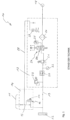
- the Fig. 2 shows a drive system 30 for raising or lowering a contact strip 31 of a current collector of a rail vehicle (not shown in detail here) via a positioning device (also not shown).
- the drive system 30 comprises a bellows drive 32 for actuating the positioning device as well as a control unit 33 and a lowering unit 34 for venting the bellows drive 32 and for quickly lowering the contact strip 31.
- the lowering unit 34 comprises a detector line 35 and a lowering valve 36 for venting the Bellows drive 32, which is designed here as a 3/2-way valve 37 and is arranged in a supply line 38 of the bellows drive 32.
- the control unit 33 is connected to a compressed air source 39 and has the supply line 38.
- the control unit 33 also includes a compressed air cleaner 40, a pressure regulator 41, a pressure gauge 42, a pressure relief valve 43, a throttle check valve 44 and another throttle valve 45.
- the control unit 33 also includes a control valve 46, which is designed here as a 5/2-way valve that can be actuated electromagnetically and is spring-reset.
- a function of the control unit 33 corresponds predominantly to a function of the Fig.1 described control unit.
- the detector line 35 is connected to a second supply line 48 of the control unit 33, via which a working pressure is generated in the detector line 35.
- the second supply line 48 is therefore connected to the supply line 38 downstream of the pressure regulator 41 and upstream of the control valve 46.
- a signal line 49 with a pressure switch 50 of the control unit 33 is also connected to the detector line 35.
- the lowering unit 34 has a throttle valve 51 in the second supply line 48. Filling or pressure increase of the signal line 49 and the detector line 35 takes place slowly via the second supply line 48 and the throttle valve 51.
- the throttle valve 51 can alternatively be designed as an orifice or constriction in the second supply line 48. If there is a pressure loss in the detector line 35, this pressure loss cannot be immediately compensated via the second supply line 48.
- the detector line 35 is connected to the 3/2-way valve 37 and allows the 3/2-way valve 37 to be operated.
- the bellows drive 32 is vented via the 3/2-way valve 37.
- This switching position is achieved by a spring return of the 3/2-way valve 37 when there is a pressure loss in the detector line 35. If a working pressure is present in the When the detector line 35 is reached, the 3/2-way valve 37 is switched to the second switching position, in which the supply line 38 is connected or no longer interrupted. Raising or lowering the contact piece 31 with the bellows drive 32 is then possible without hindrance.
Landscapes
- Engineering & Computer Science (AREA)
- Mechanical Engineering (AREA)
- General Engineering & Computer Science (AREA)
- Power Engineering (AREA)
- Transportation (AREA)
- Physics & Mathematics (AREA)
- Fluid Mechanics (AREA)
- Current-Collector Devices For Electrically Propelled Vehicles (AREA)
- Fluid-Pressure Circuits (AREA)
- Fluid-Driven Valves (AREA)
- Multiple-Way Valves (AREA)
- Control Of Fluid Pressure (AREA)
Description
- Die Erfindung betrifft ein Antriebsystem sowie ein Verfahren zum Anheben oder Absenken zumindest eines Schleifstücks eines Stromabnehmers für Schienenfahrzeuge, wobei das Schleifstück an einer mit dem Antriebsystem verstellbaren Positioniervorrichtung des Stromabnehmers angeordnet und mit einer Andruckkraft zur Anlage gegen eine Fahrleitung bringbar ist, wobei das Antriebsystem einen mit Druckluft betätigbaren Balgantrieb zur Betätigung der Positioniervorrichtung, eine pneumatische Steuereinheit mit einem Steuerventil zur Zuleitung oder Abführung von Druckluft für den Balgantrieb, und eine Absenkeinheit mit einer pneumatischen Detektorleitung und einem Absenkventil zur Entlüftung des Balgantriebs bei einem Druckverlust in der Detektorleitung umfasst. Eine ähnliche Anordnung ist bekannt aus dem Gebrauchstmuster
CN208149090 U (Xie Aihua ). - Schleifstücke aus Grafit werden regelmäßig zur Energieübertragung von einem Fahrdraht auf ein Fahrzeug, wie beispielsweise eine Lokomotive verwendet. Bei einer starken Abnutzung oder Beschädigung des Schleifstücks kann es unter anderem zu einer Beschädigung des Fahrdrahts bzw. einer Oberleitung kommen. Lokomotiven sind daher regelmäßig mit einer Sensorik ausgestattet, die ein Absenken der Schleifleiste mit dem Schleifstück bzw. einer das Schleifstück tragenden Positioniervorrichtung, wie beispielsweise eines sogenannten Pantografen oder dergleichen, bewirkt, wenn eine bestimmte Verschleißgrenze des Schleifstücks überschritten ist oder Beschädigungen am Schleifstück auftreten. Die Sensorik umfasst ein Sensorelement, welches als beispielsweise ein fluiddichter Kanal oder als ein Rohrprofil in dem Schleifstück ausgebildet bzw. angeordnet sein kann. Das Sensorelement bildet so eine Detektorleitung aus, die mit Druckluft beaufschlagt wird. Bei Erreichen einer Verschleißgrenze oder bei einer Beschädigung des Schleifstücks kommt es zu einem Anschleifen der Detektorleitung und zu einem Entweichen von Druckluft. Der Druckverlust in der Detektorleitung kann detektiert werden, worauf ein Absenken des Schleifstücks mit der Positioniervorrichtung erfolgt. Eine ähnliche Anordnung ist bekannt aus der Patentanmeldung
EP0311048 A1 (Siemens AG) . - Um Beschädigungen zu vermeiden, ist es wesentlich, dass ein Absenken des Schleifstücks von der Fahrleitung möglichst schnell erfolgt, weshalb dies mit einer speziell dazu ausgebildeten Absenkeinheit ausgeführt wird. Im Unterschied zur Steuereinheit, mit der ein reguläres Anheben und Absenken des Schleifstücks gesteuert bzw. ausgeführt wird, soll mit der Absenkeinheit ein vergleichsweise schnelles Absenken des Schleifstücks bei einer Detektion eines Druckverlustes bewirkt werden. Die Absenkeinheit weist daher regelmäßig ein an die Detektorleitung angeschlossenes Absenkventil auf, welches ein Differenzdruckventil ist. Das Differenzdruckventil ist unmittelbar an einem Balgantrieb zum Anheben oder Absenken der Schleifleiste mit der Positioniervorrichtung angeschlossen, so dass der Balgantrieb schnell entlüftet werden kann. Eine Entlüftung über die Steuereinheit ist zwar prinzipiell auch möglich, wobei diese jedoch aufgrund der langen Leitungswege und in einer pneumatischen Schaltung der Steuereinheit enthaltene Ventile keine schnelle Entlüftung erlaubt. Bei einer Detektion eines Druckabfalls durch das Differenzdruckventil wird eine Versorgungsleitung des Balgantriebs von dem Differenzdruckventil so geöffnet, dass die im Balgantrieb enthaltene Druckluft ungehindert an der Versorgungsleitung entweichen kann.
- Bei dem Differenzdruckventil kann es sich um ein 2/2-Wegeventil handeln, welches beispielsweise als ein Membranventil ausgeführt ist. Nach einer Reparatur oder einem Austausch der Detektorleitung bzw. des Schleifstücks kann ein Anheben des Schleifstücks erst wieder nach einer Rückstellung des Differenzdruckventils bzw. einer Behebung eines Schadens, welcher zu einem Druckverlust geführt hat, erfolgen, da sonst Druckluft aus der Versorgungsleitung entweichen würde. Wie sich gezeigt hat, ist eine allgemeine Funktion des Differenzdruckventils, wie beispielsweise eine Rückstellung des Differenzdruckventils bei sehr hohen oder auch niedrigen Temperaturen nicht verlässlich gegeben.
- Der vorliegenden Erfindung liegt daher die Aufgabe zugrunde, ein Antriebsystem sowie ein Verfahren zum Anheben oder Absenken eines Schleifstücks eines Stromabnehmers vorzuschlagen, welches einen verlässlichen Betrieb des Antriebsystems ermöglicht.
- Diese Aufgabe wird durch ein Antriebsystem mit den Merkmalen des Anspruchs 1, einen Stromabnehmer mit den Merkmalen des Anspruchs 13 sowie ein Verfahren mit den Merkmalen des Anspruchs 14 gelöst.
- Mit dem erfindungsgemäßen Antriebsystem zum Anheben oder Absenken zumindest eines Schleifstücks eines Stromabnehmers für Schienenfahrzeuge kann das Schleifstück an einer mit dem Antriebsystem verstellbaren Positioniervorrichtung des Stromabnehmers angeordnet und mit einer Andruckkraft zur Anlage gegen eine Fahrleitung gebracht werden, wobei das Antriebsystem einen mit Druckluft betätigbaren Balgantrieb zur Betätigung der Positioniervorrichtung, eine pneumatische Steuereinheit mit einem Steuerventil zur Zuleitung oder Abführung von Druckluft zu dem Balgantrieb, und eine Absenkeinheit mit einer pneumatischen Detektorleitung und einem Absenkventil zur Entlüftung des Balgantriebs bei einem Druckverlust in der Detektorleitung umfasst, wobei das Absenkventil ein 3/2-Wegeventil ist, wobei das Absenkventil in einer pneumatischen Versorgungsleitung zwischen dem Steuerventil und dem Balgantrieb angeordnet ist.
- Das erfindungsgemäße Antriebsystem ist demnach so ausgebildet, dass mit der Steuereinheit bzw. deren Steuerventil dem Balgantrieb zum Anheben oder Absenken des Schleifstücks über die Positioniervorrichtung Druckluft zugeleitet oder abgeführt werden kann. Zusätzlich weist das Antriebsystem die Absenkeinheit auf, die die Detektorleitung umfasst, und mit der ein Druckverlust in der Detektorleitung festgestellt werden kann. Das Absenkventil ist hier als ein 3/2-Wegeventil ausgebildet und in der Versorgungsleitung des Balgantriebs zwischen dem Steuerventil und dem Balgantrieb angeordnet. Das 3/2-Wegeventil ermöglicht durch diese Anordnung eine schnelle Entlüftung des Balgantriebs noch vor dem Steuerventil. Insbesondere durch die Ausbildung des Absenkventils durch ein 3/2-Wegeventil wird es möglich, dieses direkt in der Versorgungsleitung des Balgantriebs anzuordnen. Mit dem 3/2-Wegeventil kann die Versorgungsleitung von dem Steuerventil zu dem Balgantrieb in einer ersten Schaltposition auf einen Durchgang für Druckluft geschaltet werden und in einer zweiten Schaltposition gegenüber dem Steuerventil abgetrennt werden, sodass dann über das 3/2-Wegeventil Druckluft aus dem Balgantrieb direkt in eine Umgebung entweichen kann.
- Insbesondere kann dann auch vorgesehen sein, dass das 3/2-Wegeventil in einer rückgestellten Schaltposition stets Druckluft aus dem Balgantrieb entweichen lässt. Weiter kann das 3/2-Wegeventil mit beispielsweise Druckluft in der Detektorleitung betätigt werden. So ist dann immer sichergestellt, dass bei einem Druckluftverlust in der Detektorleitung ein Umschalten des 3/2-Wegeventils in die Schaltposition erfolgt, bei der Druckluft aus dem Balgantrieb entweicht. Da ein 3/2-Wegeventil bei der hier vorgesehenen Anwendung vergleichsweise verlässlicher ist als ein 2/2-Wegeventil bzw. Differenzdruckventil, kann auch ein Anheben des Schleifstücks nach einer Reparatur oder einem Austausch der Detektorleitung ohne eine unerwünschte Blockade des Absenkventils verlässlich erfolgen.
- Besonders vorteilhaft ist es, wenn das Absenkventil ein federrückstellbares 3/2-Wegeventil ist. Mit der Federrückstellung kann das Absenkventil dann in eine Schaltposition bewegt werden, bei der der Balgantrieb schnell entlüftet wird. So kann dann in jedem Fall sichergestellt werden, dass bei einem Druckverlust in der Detektorleitung das Schleifstück abgesenkt wird. Das Absenkventil kann pneumatisch über die Detektorleitung betätigbar sein, derart, dass bei einem Arbeitsdruck in der Detektorleitung das Absenkventil die Versorgungsleitung öffnet und bei einem Druckverlust in der Detektorleitung das Absenkventil die Versorgungsleitung gegenüber dem Steuerventil schließt und den Antriebsbalg entlüftet. Die pneumatische Betätigung des Absenkventils bzw. des 3/2-Wegeventils kann durch einen Arbeitsdruck in der Detektorleitung erfolgen. Tritt ein Druckverlust relativ zum Arbeitsdruck in der Detektorleitung auf, kann das Absenkventil in die Schaltposition rückgestellt werden, die den Antriebsbalg entlüftet.
- Die Detektorleitung kann an eine zweite pneumatische Versorgungsleitung der Steuereinheit zur Ausbildung des Arbeitsdrucks in der Detektorleitung angeschlossen sein, wobei in der zweiten Versorgungsleitung ein Drosselventil der Absenkeinheit angeordnet sein kann. Über die zweite Versorgungsleitung kann die Detektorleitung wieder mit Druckluft soweit befüllt werden, bis ein Arbeitsdruck in der Detektorleitung erreicht ist. Dadurch, dass in der zweiten Versorgungsleitung das Drosselventil angeordnet ist, wird der Arbeitsdruck nach einem Druckverlust in der Detektorleitung zeitverzögert ausgeglichen. Dies bedeutet, dass es bei einem Druckverlust in der Detektorleitung zu einer Schaltung des Absenkventils kommt, da der Druckverlust in der Detektorleitung nicht schnell genug über die zweite Versorgungsleitung kompensiert werden kann. Andernfalls würde der Druckverlust über die zweite Versorgungsleitung gegebenenfalls ausgeglichen werden, was eine Betätigung des Absenkventils in unerwünschter Weise behindern würde.
- Die zweite Versorgungsleitung kann zwischen dem Steuerventil und einer Druckluftquelle oder dem Steuerventil und einem Druckregler zur Ausbildung eines Arbeitsdrucks angeschlossen sein. So kann sichergestellt werden, dass die zweite Versorgungsleitung unabhängig von dem Steuerventil mit Druckluft beaufschlagt werden kann und nicht von einer Schaltposition des Steuerventils beeinflusst ist.
- Die Absenkeinheit kann über eine pneumatische Meldeleitung mit der Steuereinheit verbunden sein, wobei die Meldeleitung an einem Druckschalter der Steuereinheit und an die Detektorleitung angeschlossen sein kann. Über die Meldeleitung kann ein Druckverlust in der Detektorleitung bei dem Druckschalter in der Steuereinheit auf pneumatischem Wege übermittelt werden. Über den Druckschalter kann beispielsweise einem Fahrzeugführer eines Schienenfahrzeugs das Absenken des Schleifstücks in Art einer Alarm- oder Statusmeldung signalisiert werden. Weiter kann über den Druckschalter ein Absenken weiterer Schleifstücke an weiteren Stromabnehmern des Schienenfahrzeugs ausgelöst werden. So kann gegebenenfalls eine Beschädigung dieser Schleifstücke verhindert werden.
- Die Steuereinheit kann einen weiteren Druckschalter aufweisen, der zwischen dem Steuerventil und dem Balgantrieb an der Versorgungsleitung angeschlossen ist. Über den weiteren Druckschalter kann beispielsweise einem Fahrzeugführer eines Schienenfahrzeugs signalisiert werden, dass die Versorgungsleitung mit Druck beaufschlagt und damit das Schleifstück angehoben ist.
- Die Steuereinheit kann an einer Druckluftquelle anschließbar sein und einen Druckregler zur Ausbildung eines Arbeitsdrucks aufweisen. Die Druckluftquelle kann von dem Schienenfahrzeug selbst ausgebildet werden. Mit dem Druckregler kann ein stets konstanter Arbeitsdruck ausgebildet werden. Weiter kann die Steuereinheit noch eine Einrichtung zur Druckluftreinigung und ein Überdruckventil zur Druckbegrenzung aufweisen.
- Das Steuerventil kann ein 5/2-Wegeventil sein, wobei das Steuerventil elektromagnetisch betätigbar sein kann. Mit der elektromagnetischen Betätigung kann beispielsweise von einem Fahrzeugführer des Schienenfahrzeugs ein Anheben oder Absenken durch einfache Betätigung eines Schalters initiiert werden. Das 5/2-Wegeventil kann so beschaffen sein, dass zum Anheben des Schleifstücks die Versorgungsleitung unmittelbar mit einer Druckluftquelle in einer ersten Schaltposition verbunden werden kann. In einer zweiten Schaltposition kann über das 5/2-Wegeventil die Druckluftquelle von der Versorgungsleitung abgetrennt bzw. verschlossen sein. Die Versorgungsleitung kann zur Entlüftung des Balgantriebs bzw. zum langsamen Absenken des Schleifstücks durch das 5/2-Wegeventil in eine Umgebung hindurchgeleitet sein. Weiter kann das 5/2-Wegeventil federrückstellbar ausgebildet sein, derart, dass in einer federrückgestellten Schaltposition die Versorgungsleitung entlüftet wird.
- Die Steuereinheit kann in der Versorgungsleitung zumindest ein Drosselrückschlagventil aufweisen, wobei das Drosselrückschlagventil zwischen dem Steuerventil und dem Balgantrieb angeschlossen sein kann, wobei mit dem Drosselrückschlagventil dem Balgantrieb über die Versorgungsleitung zugeführte Druckluft drosselbar und von dem Balgantrieb abgeführte Druckluft durchleitbar sein kann oder umgekehrt. Mit dem Drosselrückschlagventil kann ein Anheben oder Absenken des Schleifstücks hinsichtlich einer Anhebe- bzw. Absenkgeschwindigkeit in der gewünschten Weise eingestellt werden. Das Drosselrückschlagventil kann so in der Versorgungsleitung angeordnet sein, dass entweder das Anheben oder das Absenken verlangsamt ist. Gleichwohl können zwei Drosselrückschlagventile in der Versorgungsleitung in einer Reihenschaltung so angeordnet sein, dass das Anheben und das Absenken durch jeweils eines der Drosselrückschlagventile verlangsamt ist.
- Die Steuereinheit kann ein weiteres Drosselventil aufweisen, wobei mit dem weiteren Drosselventil dem Balgantrieb über die Versorgungsleitung zugeführte Druckluft oder dem Balgantrieb abgeführte Druckluft drosselbar sein kann. Wenn nur ein Drosselrückschlagventil in der Versorgungsleitung vorgesehen ist, kann beispielsweise das weitere Drosselventil so angeordnet sein, dass bei einem Entlüften der Versorgungsleitung über das Steuerventil das Entlüften mit dem weiteren Drosselventil verlangsamt wird, sodass ein langsames Absenken des Schleifstücks erfolgt. Das weitere Drosselventil kann zu diesem Zweck mit einem Schalldämpfer ausgebildet sein.
- Die Steuereinheit, die Absenkeinheit und der Balgantrieb können räumlich voneinander getrennt angeordnet sein. Das Absenkventil bzw. die Absenkeinheit können vorteilhaft in der Nähe des Balgantriebs angeordnet sein, sodass eine schnelle Entlüftung des Balgantriebs sowie eine kurze Verbindung mit der Detektorleitung möglich ist. Die Steuereinheit kann zum Schutz vor unzuträglichen Umwelteinflüssen innerhalb des Schienenfahrzeugs oder in einem gesondert angeordneten Gehäuse auf dem Schienenfahrzeug angeordnet und über entsprechende Druckluftleitungen mit dem Balgantrieb bzw. der Absenkeinheit verbunden sein.
- Der erfindungsgemäße Stromabnehmer weist eine Positioniervorrichtung auf und zumindest ein an der Positioniervorrichtung angeordnetes Schleifstück sowie ein pneumatisches Antriebsystem nach der Erfindung. Weitere vorteilhafte Ausführungsformen eines Stromabnehmers ergeben sich aus den Merkmalsbeschreibungen der auf den Anspruch 1 zurückbezogenen Unteransprüche.
- Bei dem erfindungsgemäßen Verfahren zum Anheben oder Absenken zumindest eines Schleifstücks eines Stromabnehmers für Schienenfahrzeuge mit einem Antriebsystem wird das Schleifstück an einer mit dem Antriebsystem verstellbaren Positioniervorrichtung des Stromabnehmers angeordnet und mit einer Andruckkraft zur Anlage gegen eine Fahrleitung gebracht, wobei die Positioniervorrichtung mit einem Balgantrieb des Antriebsystems mit Druckluft betätigt wird, wobei von einem Steuerventil einer pneumatischen Steuereinheit des Antriebsystems Druckluft zu dem Balgantrieb zugeleitet oder abgeführt wird, und wobei mit einer pneumatischen Detektorleitung und einem Absenkventil einer Absenkeinheit des Antriebsystems bei einem Druckverlust in der Detektorleitung der Balgantrieb entlüftet wird, wobei als Absenkventil ein rückstellbares 3/2-Wegeventil verwendet wird, wobei das Absenkventil in einer pneumatischen Versorgungsleitung zwischen dem Steuerventil und dem Balgantrieb angeordnet wird. Zu den Vorteilen des erfindungsgemäßen Verfahrens wird auf die Vorteilsbeschreibung des erfindungsgemäßen Antriebsystems verwiesen.
- Bei einem erfolgten Druckverlust in der Detektorleitung kann relativ zu einem von einem Druckregler der Steuereinheit ausgebildeten Arbeitsdruck das Absenkventil derart geschaltet werden, dass der Balgantrieb unmittelbar über das Absenkventil entlüftet und das Schleifstück abgesenkt wird.
- Bei einer dicht abgeschlossenen Detektorleitung kann diese mit Druckluft bis zum Erreichen eines von einem Druckregler der Steuereinheit ausgebildeten Arbeitsdrucks befüllt werden, wobei bei Erreichen des Arbeitsdrucks in der Detektorleitung das Absenkventil derart geschaltet werden kann, dass der Balgantrieb unmittelbar über die Versorgungsleitung mit Druckluft angetrieben und das Schleifstück angehoben werden kann.
- Weitere vorteilhafte Ausführungsformen des Verfahrens ergeben sich aus den Merkmalsbeschreibungen der auf den Anspruch 1 zurückbezogenen Unteransprüche.
- Im Folgenden wird die Erfindung unter Bezugnahme auf die beigefügten Zeichnungen näher erläutert.
- Es zeigen:
- Fig. 1
- einen Schaltplan eines Antriebsystems nach dem Stand der Technik;
- Fig. 2
- einen Schaltplan eines Antriebsystems.
- Die
Fig. 1 zeigt einen aus dem Stand der Technik bekannten Schaltplan eines Antriebsystems zum Anheben oder Absenken eines Schleifstücks 11 eines hier nicht weiter dargestellten Stromabnehmers für Schienenfahrzeuge nach dem Stand der Technik. Das Schleifstück 11 ist an einer mit dem Antriebsystem 10 verstellbaren Positioniervorrichtung des Stromabnehmers angeordnet, die ebenfalls hier nicht näher dargestellt ist. Die Positioniervorrichtung kann beispielsweise ein sogenannter Pantograf oder ein anderes Hebelarmsystem sein. Weiter umfasst das Antriebsystem 10 einen Balgantrieb 12 zur Betätigung der Positioniervorrichtung. Durch ein Füllen des Balgantriebs 12 mit Druckluft wird das Schleifstück 11 über die Positioniervorrichtung gegen eine hier nicht dargestellte Fahrleitung zur Anlage gebracht, wobei bei einem Entlüften des Balgantriebs 12 das Schleifstück 11 wieder abgesenkt wird. - Weiter umfasst das Antriebsystem 10 eine Steuereinheit 13 und eine Absenkeinheit 14. Die Absenkeinheit 14 ist aus einer pneumatischen Detektorleitung 15 und einem Absenkventil 16, welches hier durch ein Differenzdruckventil 17 bzw. 2/2-Wegeventil ausgebildet ist, ausgebildet. Die Steuereinheit 13 ist an einer Druckluftquelle 18 angeschlossen und über eine Versorgungsleitung 19 mit dem Balgantrieb 12 verbunden. Die Steuereinheit 13 umfasst einen Druckluftreiniger 20, einen Druckregler 21 zur Ausbildung eines Arbeitsdrucks, ein Manometer 22 zur Anzeige eines Arbeitsdrucks, ein Überdruckventil 23 zur Begrenzung eines Arbeitsdrucks, ein Drosselrückschlagventil 24, ein weiteres Drosselventil 25 und ein Steuerventil 26. Das Steuerventil 26 ist durch ein 5/2-Wegeventil 27 mit elektromagnetischem Antrieb und Federrückstellung ausgebildet.
- Bei der in der
Fig. 1 dargestellten Schaltposition des Steuerventils 26 wird der Balgantrieb 12 entlüftet. Die Entlüftung erfolgt dabei über das weitere Drosselventil 25, wodurch ein langsames Absenken des Schleifstücks 11 bewirkt wird. Beim Anheben des Schleifstücks 11 steht das Steuerventil 26 in seiner zweiten Schaltposition, in der die Einleitung von Druckluft in den Balgantrieb 12 über das Drosselrückschlagventil 24 ebenfalls verlangsamt erfolgt. - Bei dem Befüllen des Balgantriebs 12 über die Versorgungsleitung 19 wird die Detektorleitung 15 ebenfalls mit Druck beaufschlagt und das Differenzdruckventil 17 wechselt von der hier dargestellten Schaltposition zur Schnellentlüftung in die zweite Schaltposition des Differenzdruckventils 17, bei der die Versorgungsleitung 19 am Differenzdruckventil 17 dicht gegenüber einer Umgebung abgeschlossen ist. Bei einem Druckverlust in der Detektorleitung 15 wird durch das Differenzdruckventil 17 eine schnelle Entlüftung der Versorgungsleitung bzw. des Balgantriebs 12 aufgrund des Druckunterschieds der Versorgungsleitung 19 und der Detektorleitung 15 ausgelöst.
- Weiter ist die Absenkeinheit mit der Steuereinheit 13 über eine Meldeleitung 28 verbunden, die direkt an die Detektorleitung 15 angeschlossen ist. Die Meldeleitung 28 wirkt auf einen Druckschalter 29 der Steuereinheit 13, mit dem ein paralleles Absenken anderer, an dem Schienenfahrzeug befindlicher Stromabnehmer initiiert werden kann.
- Die
Fig. 2 zeigt ein Antriebsystem 30 zum Anheben oder Absenken eines Schleifstücks 31 eines hier nicht näher dargestellten Stromabnehmers eines Schienenfahrzeugs über eine ebenfalls nicht gezeigte Positioniervorrichtung. Das Antriebsystem 30 umfasst einen Balgantrieb 32 zur Betätigung der Positioniervorrichtung sowie eine Steuereinheit 33 und eine Absenkeinheit 34 zur Entlüftung des Balgantriebs 32 und zum schnellen Absenken des Schleifstücks 31. Die Absenkeinheit 34 umfasst eine Detektorleitung 35 und ein Absenkventil 36 zur Entlüftung des Balgantriebs 32, welches hier als ein 3/2-Wegeventil 37 ausgebildet und in einer Versorgungsleitung 38 des Balgantriebs 32 angeordnet ist. - Die Steuereinheit 33 ist an einer Druckluftquelle 39 angeschlossen und weist die Versorgungsleitung 38 auf. Auch umfasst die Steuereinheit 33 einen Druckluftreiniger 40, einen Druckregler 41, ein Manometer 42, ein Überdruckventil 43, ein Drosselrückschlagventil 44 und ein weiteres Drosselventil 45. Weiter umfasst die Steuereinheit 33 ein Steuerventil 46, welches hier als 5/2-Wegeventil, das elektromagnetisch betätigbar und federrückstellbar ist, ausgebildet ist. Eine Funktion der Steuereinheit 33 entspricht überwiegend einer Funktion der in der
Fig. 1 beschriebenen Steuereinheit. Im Unterschied dazu ist hier die Detektorleitung 35 an eine zweite Versorgungsleitung 48 der Steuereinheit 33 angeschlossen, über die ein Arbeitsdruck in der Detektorleitung 35 ausgebildet wird. Die zweite Versorgungsleitung 48 ist daher nachfolgend dem Druckregler 41 und vor dem Steuerventil 46 an der Versorgungsleitung 38 angeschlossen. Auch ist an die Detektorleitung 35 eine Meldeleitung 49 mit einem Druckschalter 50 der Steuereinheit 33 angeschlossen. - Die Absenkeinheit 34 verfügt neben dem Absenkventil 36 über ein Drosselventil 51 in der zweiten Versorgungsleitung 48. Eine Füllung bzw. Druckerhöhung der Meldeleitung 49 und der Detektorleitung 35 erfolgt verlangsamt über die zweite Versorgungsleitung 48 und das Drosselventil 51. Das Drosselventil 51 kann hier alternativ auch als eine Blende bzw. Engstelle in der zweiten Versorgungsleitung 48 ausgebildet sein. Bei einem Druckverlust in der Detektorleitung 35 kann dann dieser Druckverlust nicht unmittelbar über die zweite Versorgungsleitung 48 ausgeglichen werden. Die Detektorleitung 35 ist an das 3/2-Wegeventil 37 angeschlossen und erlaubt eine Betätigung des 3/2-Wegeventils 37.
- In der hier dargestellten Schaltposition wird über das 3/2-Wegeventil 37 der Balgantrieb 32 entlüftet. Diese Schaltposition wird durch eine Federrückstellung des 3/2-Wegeventils 37 erreicht, wenn ein Druckverlust in der Detektorleitung 35 vorliegt. Ist ein Arbeitsdruck in der Detektorleitung 35 erreicht, wird das 3/2-Wegeventil 37 in die zweite Schaltposition geschaltet, bei der die Versorgungsleitung 38 durchgeschaltet bzw. nicht mehr unterbrochen ist. Ein Anheben oder ein Absenken des Schleifstücks 31 mit dem Balgantrieb 32 ist dann ungehindert möglich.
Claims (16)
- Antriebsystem (30) zum Anheben oder Absenken zumindest eines Schleifstücks (31) eines Stromabnehmers für Schienenfahrzeuge, wobei das Schleifstück an einer mit dem Antriebsystem verstellbaren Positioniervorrichtung des Stromabnehmers angeordnet und mit einer Andruckkraft zur Anlage gegen eine Fahrleitung bringbar ist, wobei das Antriebsystem einen mit Druckluft betätigbaren Balgantrieb (32) zur Betätigung der Positioniervorrichtung, eine pneumatische Steuereinheit mit einem Steuerventil (46) zur Zuleitung oder Abführung von Druckluft zu dem Balgantrieb, und eine Absenkeinheit (34) mit einer pneumatischen Detektorleitung (35) und einem Absenkventil (36) zur Entlüftung des Balgantriebs bei einem Druckverlust in der Detektorleitung umfasst, wobei das Absenkventil ein 3/2-Wegeventil (37) ist, wobei das Absenkventil in einer pneumatischen Versorgungsleitung (38) zwischen dem Steuerventil und dem Balgantrieb angeordnet ist.
- Antriebsystem nach Anspruch 1,
dadurch gekennzeichnet,
dass das Absenkventil ein federrückstellbares 3/2-Wegeventil ist. - Antriebsystem nach Anspruch 1 oder 2,
dadurch gekennzeichnet,
dass das Absenkventil (36) pneumatisch über die Detektorleitung (35) betätigbar ist, derart, dass bei einem Arbeitsdruck in der Detektorleitung das Absenkventil die Versorgungsleitung (38) öffnet und bei einem Druckverlust in der Detektorleitung das Absenkventil die Versorgungsleitung gegenüber dem Steuerventil schließt und den Balgantrieb (32) entlüftet. - Antriebsystem nach einem der vorangehenden Ansprüche,
dadurch gekennzeichnet,
dass die Detektorleitung (35) an eine zweite pneumatische Versorgungsleitung (48) der Steuereinheit (33) zur Ausbildung des Arbeitsdrucks in der Detektorleitung angeschlossen ist, wobei in der zweiten Versorgungsleitung ein Drosselventil (51) der Absenkeinheit (34) angeordnet ist. - Antriebsystem nach Anspruch 4,
dadurch gekennzeichnet,
dass die zweite Versorgungsleitung (48) zwischen dem Steuerventil (46) und einer Druckluftquelle (39) oder dem Steuerventil und einem Druckregler (41) zur Ausbildung eines Arbeitsdrucks angeschlossen ist. - Antriebsystem nach einem der vorangehenden Ansprüche,
dadurch gekennzeichnet,
dass die Absenkeinheit (34) über eine pneumatische Meldeleitung (49) mit der Steuereinheit (33) verbunden ist, wobei die Meldeleitung an einen Druckschalter (50) der Steuereinheit und die Detektorleitung (35) angeschlossen ist. - Antriebsystem nach einem der vorangehenden Ansprüche,
dadurch gekennzeichnet,
dass die Steuereinheit (33) einen weiteren Druckschalter aufweist, der zwischen dem Steuerventil (46) und dem Balgantrieb (32) an der Versorgungsleitung (38) angeschlossen ist. - Antriebsystem nach einem der vorangehenden Ansprüche,
dadurch gekennzeichnet,
dass die Steuereinheit (33) an eine Druckluftquelle (39) anschließbar ist und einen Druckregler (41) zur Ausbildung eines Arbeitsdrucks aufweist. - Antriebsystem nach einem der vorangehenden Ansprüche,
dadurch gekennzeichnet,
dass das Steuerventil (46) ein 5/2-Wegeventil (47) ist, wobei das Steuerventil elektromagnetisch betätigbar ist. - Antriebsystem nach einem der vorangehenden Ansprüche,
dadurch gekennzeichnet,
dass die Steuereinheit (33) in der Versorgungsleitung (38) zumindest ein Drosselrückschlagventil (44) aufweist, wobei das Drosselrückschlagventil zwischen dem Steuerventil (46) und dem Balgantrieb (32) angeschlossen ist, wobei mit dem Drosselrückschlagventil dem Balgantrieb über die Versorgungsleitung zugeführte Druckluft drosselbar und von dem Balgantrieb abgeführte Druckluft durchleitbar ist oder umgekehrt. - Antriebsystem nach Anspruch 10,
dadurch gekennzeichnet,
dass die Steuereinheit (33) ein weiteres Drosselventil (45) aufweist, wobei mit dem weiteren Drosselventil dem Balgantrieb (32) über die Versorgungsleitung (38) zugeführte Druckluft oder dem Balgantrieb abgeführte Druckluft drosselbar ist. - Antriebsystem nach einem der vorangehenden Ansprüche,
dadurch gekennzeichnet,
dass die Steuereinheit (33), die Absenkeinheit (34) und der Balgantrieb (32) räumlich getrennt angeordnet sind. - Stromabnehmer mit einer Positioniervorrichtung, zumindest einem an der Positioniervorrichtung angeordneten Schleifstück (31) und einem pneumatischen Antriebsystem (30) nach einem der vorangehenden Ansprüche.
- Verfahren zum Anheben oder Absenken zumindest eines Schleifstücks (31) eines Stromabnehmers für Schienenfahrzeuge mit einem Antriebssystem (30), wobei das Schleifstück an einer mit dem Antriebsystem verstellbaren Positioniervorrichtung des Stromabnehmers angeordnet und mit einer Andruckkraft zur Anlage gegen eine Fahrleitung gebracht wird, wobei die Positioniervorrichtung mit einem Balgantrieb (32) des Antriebsystems mit Druckluft betätigt wird, wobei von einem Steuerventil (46) einer pneumatische Steuereinheit (33) des Antriebsystems Druckluft zu dem Balgantrieb zugeleitet oder abgeführt wird, und wobei mit einer pneumatischen Detektorleitung (35) und einem Absenkventil (36) einer Absenkeinheit (34) des Antriebsystems bei einem Druckverlust in der Detektorleitung der Balgantrieb entlüftet wird, wobei als Absenkventil ein rückstellbares 3/2-Wegeventil (37) verwendet wird, wobei das Absenkventil in einer pneumatischen Versorgungsleitung (38) zwischen dem Steuerventil und dem Balgantrieb angeordnet wird.
- Verfahren nach Anspruch 14,
dadurch gekennzeichnet,
dass bei einem erfolgten Druckverlust in der Detektorleitung (35) relativ zu einem vom einem Druckregler (41) der Steuereinheit (33) ausgebildeten Arbeitsdruck das Absenkventil (36) derart geschaltet wird, dass der Balgantrieb (32) unmittelbar über das Absenkventil entlüftet und das Schleifstück (31) abgesenkt wird. - Verfahren nach Anspruch 14 oder 15,
dadurch gekennzeichnet,
dass bei einer dicht abgeschlossenen Detektorleitung (35) diese mit Druckluft bis zum Erreichen eines von einem Druckregler (41) der Steuereinheit (33) ausgebildeten Arbeitsdrucks befüllt wird, wobei bei Erreichen des Arbeitsdrucks in der Detektorleitung das Absenkventil (36) derart geschaltet wird, dass der Balgantrieb (32) unmittelbar über die Versorgungsleitung (38) mit Druckluft angetrieben und das Schleifstück (31) angehoben wird.
Priority Applications (2)
| Application Number | Priority Date | Filing Date | Title |
|---|---|---|---|
| RS20241250A RS66411B1 (sr) | 2019-08-12 | 2019-08-12 | Pogonski sistem za pantograf i postupak za podizanje ili spuštanje |
| PL19762322.6T PL4013636T3 (pl) | 2019-08-12 | 2019-08-12 | Układ napędowy odbieraka prądu oraz sposób podnoszenia lub opuszczania |
Applications Claiming Priority (1)
| Application Number | Priority Date | Filing Date | Title |
|---|---|---|---|
| PCT/EP2019/071626 WO2021028019A1 (de) | 2019-08-12 | 2019-08-12 | Antriebsystem für einen stromabnehmer und verfahren zum anheben oder absenken |
Publications (2)
| Publication Number | Publication Date |
|---|---|
| EP4013636A1 EP4013636A1 (de) | 2022-06-22 |
| EP4013636B1 true EP4013636B1 (de) | 2024-09-25 |
Family
ID=67841033
Family Applications (1)
| Application Number | Title | Priority Date | Filing Date |
|---|---|---|---|
| EP19762322.6A Active EP4013636B1 (de) | 2019-08-12 | 2019-08-12 | Antriebsystem für einen stromabnehmer und verfahren zum anheben oder absenken |
Country Status (10)
| Country | Link |
|---|---|
| US (1) | US12459367B2 (de) |
| EP (1) | EP4013636B1 (de) |
| JP (1) | JP2022549062A (de) |
| KR (1) | KR102896222B1 (de) |
| CN (1) | CN114401860B (de) |
| CA (1) | CA3148652A1 (de) |
| ES (1) | ES2999508T3 (de) |
| PL (1) | PL4013636T3 (de) |
| RS (1) | RS66411B1 (de) |
| WO (1) | WO2021028019A1 (de) |
Families Citing this family (5)
| Publication number | Priority date | Publication date | Assignee | Title |
|---|---|---|---|---|
| US20230382232A1 (en) * | 2022-05-24 | 2023-11-30 | Faiveley Transport Tours | Pantograph positioning system |
| DE102022210380A1 (de) * | 2022-09-30 | 2024-04-04 | Siemens Mobility GmbH | Stromabnehmer mit Bruchüberwachung |
| KR102711611B1 (ko) * | 2022-11-08 | 2024-09-30 | 유진기공산업주식회사 | 반능동형 팬터그래프 공압 제어 시스템 |
| KR102848822B1 (ko) * | 2023-09-20 | 2025-08-22 | 유진기공산업주식회사 | 반능동형 팬터그래프 공압 제어 시스템 |
| KR102823499B1 (ko) * | 2023-09-22 | 2025-06-20 | 유진기공산업주식회사 | 반능동형 팬터그래프 fail safe 공압 제어 시스템 |
Citations (9)
| Publication number | Priority date | Publication date | Assignee | Title |
|---|---|---|---|---|
| JPS5546805A (en) | 1978-09-29 | 1980-04-02 | Japanese National Railways<Jnr> | Failure detector of pantograph |
| EP0311048B1 (de) | 1987-10-08 | 1993-03-10 | Siemens Aktiengesellschaft Österreich | Halbscherenstromabnehmer mit Einrichtung zur Verhinderung mechanischer Überlastung |
| EP0395504B1 (de) | 1989-04-28 | 1994-07-27 | Faiveley Transport | Vorrichtung zum Regeln der Anpresskraft eines Scherenstromabnehmers gegen einen Fahrdraht und Verfahren zu ihrer Herstellung |
| EP0449704B1 (de) | 1990-03-28 | 1996-06-26 | Faiveley Transport | Scherenstromabnehmer |
| DE10324790A1 (de) | 2003-04-22 | 2004-12-02 | Schunk Bahntechnik Gmbh, Bergheim | Stromabnehmer |
| JP2007189754A (ja) | 2006-01-11 | 2007-07-26 | Toyo Electric Mfg Co Ltd | 車両用パンタグラフ |
| EP1862347A1 (de) | 2006-05-29 | 2007-12-05 | Faiveley Transport | System zur Steuerung eines Pantographen, Umsetzungsverfahren und Modul zur Steuerung eines solchen Systems |
| CN208149090U (zh) | 2017-12-11 | 2018-11-27 | 谢爱华 | 一种机车受电弓升弓风压降低后的降弓保护装置 |
| EP3337685B1 (de) | 2015-08-21 | 2021-07-28 | KNORR-BREMSE Systeme für Schienenfahrzeuge GmbH | Verfahren und einrichtung zur haupt- und hilfsluftversorgung, insbesondere eines schienenfahrzeuges |
Family Cites Families (7)
| Publication number | Priority date | Publication date | Assignee | Title |
|---|---|---|---|---|
| JPH0797881B2 (ja) * | 1986-07-29 | 1995-10-18 | 東洋電機製造株式会社 | トロリ−アシスト車両用パンタグラフの架線外れ検知装置 |
| FR2692528B1 (fr) * | 1992-06-17 | 1995-01-20 | Delachaux Sa | Dispositif de captation d'électricité pour un véhicule tel qu'un trolleybus ou un tramway. |
| DE10126042A1 (de) | 2000-06-06 | 2002-01-24 | Siemens Ag Oesterreich | Pneumatische Steuerung eines Stromabnehmers elektrischer Triebfahrzeuge |
| CN202294326U (zh) * | 2011-11-08 | 2012-07-04 | 北京赛德高科铁道电气科技有限责任公司 | 一种受电弓的自动升降弓装置 |
| DE102013217429A1 (de) | 2013-09-02 | 2015-03-05 | Siemens Aktiengesellschaft | Druckluftsystem |
| CN206344692U (zh) * | 2016-12-12 | 2017-07-21 | 中车株洲电力机车有限公司 | 一种城轨车辆受电弓 |
| US11969255B2 (en) | 2021-12-12 | 2024-04-30 | Biosense Webster (Israel) Ltd. | Detection of fractionated signals in stable arrhythmias |
-
2019
- 2019-08-12 WO PCT/EP2019/071626 patent/WO2021028019A1/de not_active Ceased
- 2019-08-12 KR KR1020227006016A patent/KR102896222B1/ko active Active
- 2019-08-12 PL PL19762322.6T patent/PL4013636T3/pl unknown
- 2019-08-12 CA CA3148652A patent/CA3148652A1/en active Pending
- 2019-08-12 ES ES19762322T patent/ES2999508T3/es active Active
- 2019-08-12 JP JP2022507522A patent/JP2022549062A/ja active Pending
- 2019-08-12 US US17/634,408 patent/US12459367B2/en active Active
- 2019-08-12 EP EP19762322.6A patent/EP4013636B1/de active Active
- 2019-08-12 CN CN201980099269.0A patent/CN114401860B/zh active Active
- 2019-08-12 RS RS20241250A patent/RS66411B1/sr unknown
Patent Citations (9)
| Publication number | Priority date | Publication date | Assignee | Title |
|---|---|---|---|---|
| JPS5546805A (en) | 1978-09-29 | 1980-04-02 | Japanese National Railways<Jnr> | Failure detector of pantograph |
| EP0311048B1 (de) | 1987-10-08 | 1993-03-10 | Siemens Aktiengesellschaft Österreich | Halbscherenstromabnehmer mit Einrichtung zur Verhinderung mechanischer Überlastung |
| EP0395504B1 (de) | 1989-04-28 | 1994-07-27 | Faiveley Transport | Vorrichtung zum Regeln der Anpresskraft eines Scherenstromabnehmers gegen einen Fahrdraht und Verfahren zu ihrer Herstellung |
| EP0449704B1 (de) | 1990-03-28 | 1996-06-26 | Faiveley Transport | Scherenstromabnehmer |
| DE10324790A1 (de) | 2003-04-22 | 2004-12-02 | Schunk Bahntechnik Gmbh, Bergheim | Stromabnehmer |
| JP2007189754A (ja) | 2006-01-11 | 2007-07-26 | Toyo Electric Mfg Co Ltd | 車両用パンタグラフ |
| EP1862347A1 (de) | 2006-05-29 | 2007-12-05 | Faiveley Transport | System zur Steuerung eines Pantographen, Umsetzungsverfahren und Modul zur Steuerung eines solchen Systems |
| EP3337685B1 (de) | 2015-08-21 | 2021-07-28 | KNORR-BREMSE Systeme für Schienenfahrzeuge GmbH | Verfahren und einrichtung zur haupt- und hilfsluftversorgung, insbesondere eines schienenfahrzeuges |
| CN208149090U (zh) | 2017-12-11 | 2018-11-27 | 谢爱华 | 一种机车受电弓升弓风压降低后的降弓保护装置 |
Non-Patent Citations (3)
| Title |
|---|
| ANONYMOUS: "Le PANTOGRAPHE CX - DESCRIPTION FONCTIONNELLE", (ACCESSED VIA THE WAYBACK MACHINE), 13 May 2013 (2013-05-13), XP093292174, Retrieved from the Internet <URL:https://web.archive.org/web/20130513005710/https://actgv.fr/wp-content/u ploads/2012/05/Le-PANTOGRAPHE-CX.pdf> |
| ANONYMOUS: "NF EN 50206-1 - Applications ferroviaires Matériel roulant Pantographes : Caractéristiques et essais", AFNOR, 1 March 2011 (2011-03-01), XP093292178 |
| ANONYMOUS: "TGV duplex.", (ACCESSED VIA THE WAYBACK MACHINE), 15 May 2013 (2013-05-15), XP093292176, Retrieved from the Internet <URL:https://web.archive.org/web/20130515184403/https://actgv.fr/wp-content/ uploads/2012/05/TGV-duplex-23-02-2012.pdf#expand> |
Also Published As
| Publication number | Publication date |
|---|---|
| KR102896222B1 (ko) | 2025-12-04 |
| JP2022549062A (ja) | 2022-11-24 |
| EP4013636A1 (de) | 2022-06-22 |
| ES2999508T3 (en) | 2025-02-26 |
| KR20220045163A (ko) | 2022-04-12 |
| CN114401860A (zh) | 2022-04-26 |
| US12459367B2 (en) | 2025-11-04 |
| US20230010860A1 (en) | 2023-01-12 |
| RS66411B1 (sr) | 2025-02-28 |
| CA3148652A1 (en) | 2021-02-18 |
| PL4013636T3 (pl) | 2025-02-17 |
| WO2021028019A1 (de) | 2021-02-18 |
| CN114401860B (zh) | 2025-06-06 |
Similar Documents
| Publication | Publication Date | Title |
|---|---|---|
| EP4013636B1 (de) | Antriebsystem für einen stromabnehmer und verfahren zum anheben oder absenken | |
| DE102015114176C5 (de) | Elektrische Parkbremseinrichtung mit zusätzlicher Energieversorgung | |
| EP2171334B1 (de) | Verfahren zur steuerung oder regelung eines vakuumventils | |
| DE102017217213B3 (de) | Pneumatisches Ventil | |
| DE102009059900A1 (de) | Ventileinrichtung, elektrisch betätigbares Feststellbremssystem und Verfahren zum Steuern eines elektrisch betätigbaren Feststellbremssystems | |
| EP2407355A1 (de) | Relaisventil und Verfahren zum Betreiben eines Relaisventils | |
| DE2303665A1 (de) | Stroemungsmittelkupplungsvorrichtung | |
| EP3700790B1 (de) | Anordnung mit einem bremskrafterzeuger und verfahren zum betreiben eines bremskrafterzeugers | |
| DE102014010174B4 (de) | Elektrohydraulisches Lenksystem und mobile Arbeitsmaschine | |
| EP3750771A1 (de) | Kupplung mit einer elektrokupplung insbesondere für ein schienenfahrzeug | |
| EP3390183B1 (de) | Vorrichtung zur erhöhung der entlüftungsgeschwindigkeit eines pneumatischen regelventils | |
| DE102015004366A1 (de) | Reifendruckregulierungseinrichtung | |
| DE102016115360A1 (de) | Überströmventil zum zumindest teilweisen Verschließen und Öffnen eines Fluidleitungssystems | |
| DE102022113470B3 (de) | Sicherheitsventilanordnung und Aktorsystem | |
| DE102013100295A1 (de) | Luftfederanlage und Ventil für ein Fahrzeug | |
| DE10209913C1 (de) | Notbremsüberbrückungseinrichtung zur Ansteuerung von elektropneumatischen Zugbremseinrichtungen in Triebfahrzeugen und Steuerwagen mit konventioneller Bremstechnik | |
| EP0388805B1 (de) | Vorrichtung zur Schnellabsenkung von Stromabnehmern elektrisch angetriebener Fahrzeuge mit pneumatischem Antrieb | |
| EP2384944B1 (de) | Verfahren zum Steuern eines elektrisch betätigbaren Feststellbremssystems | |
| AT528314B1 (de) | Pneumatische Antriebsanordnung, Stromabnehmer und Fahrzeug | |
| EP0349751B1 (de) | Notbremseinrichtung für indirekt wirkende Druckluftbremse | |
| EP3194228A1 (de) | Verfahren und betätigungsvorrichtung zur enteisung eines schienenfahrzeuges | |
| DE102014113560A1 (de) | Stromabnehmersystem mit pneumatischer Sensorüberwachung | |
| DE102013010031A1 (de) | Kupplungskopfeinheit für ein Nutzfahrzeug und Verfahren zum Ankoppeln einer Versorgungsleitung und einer Steuerleitung an eine pneumatisch betriebene Bremsanlage | |
| DE102014007281A1 (de) | Reifendruckverstellanlage für einkanalige Drehdurchführungen | |
| DE102008038722A1 (de) | Ventileinrichtung und Verfahren zur Ansteuerung eines von einem Stellungsregler druckmittelbeaufschlagten Stellantriebs |
Legal Events
| Date | Code | Title | Description |
|---|---|---|---|
| STAA | Information on the status of an ep patent application or granted ep patent |
Free format text: STATUS: UNKNOWN |
|
| STAA | Information on the status of an ep patent application or granted ep patent |
Free format text: STATUS: THE INTERNATIONAL PUBLICATION HAS BEEN MADE |
|
| PUAI | Public reference made under article 153(3) epc to a published international application that has entered the european phase |
Free format text: ORIGINAL CODE: 0009012 |
|
| STAA | Information on the status of an ep patent application or granted ep patent |
Free format text: STATUS: REQUEST FOR EXAMINATION WAS MADE |
|
| 17P | Request for examination filed |
Effective date: 20220125 |
|
| AK | Designated contracting states |
Kind code of ref document: A1 Designated state(s): AL AT BE BG CH CY CZ DE DK EE ES FI FR GB GR HR HU IE IS IT LI LT LU LV MC MK MT NL NO PL PT RO RS SE SI SK SM TR |
|
| DAV | Request for validation of the european patent (deleted) | ||
| DAX | Request for extension of the european patent (deleted) | ||
| GRAP | Despatch of communication of intention to grant a patent |
Free format text: ORIGINAL CODE: EPIDOSNIGR1 |
|
| STAA | Information on the status of an ep patent application or granted ep patent |
Free format text: STATUS: GRANT OF PATENT IS INTENDED |
|
| INTG | Intention to grant announced |
Effective date: 20240429 |
|
| GRAS | Grant fee paid |
Free format text: ORIGINAL CODE: EPIDOSNIGR3 |
|
| GRAA | (expected) grant |
Free format text: ORIGINAL CODE: 0009210 |
|
| STAA | Information on the status of an ep patent application or granted ep patent |
Free format text: STATUS: THE PATENT HAS BEEN GRANTED |
|
| RIN1 | Information on inventor provided before grant (corrected) |
Inventor name: GRUBER, ALEXANDER |
|
| AK | Designated contracting states |
Kind code of ref document: B1 Designated state(s): AL AT BE BG CH CY CZ DE DK EE ES FI FR GB GR HR HU IE IS IT LI LT LU LV MC MK MT NL NO PL PT RO RS SE SI SK SM TR |
|
| REG | Reference to a national code |
Ref country code: GB Ref legal event code: FG4D Free format text: NOT ENGLISH |
|
| REG | Reference to a national code |
Ref country code: CH Ref legal event code: EP |
|
| REG | Reference to a national code |
Ref country code: DE Ref legal event code: R096 Ref document number: 502019012201 Country of ref document: DE |
|
| REG | Reference to a national code |
Ref country code: IE Ref legal event code: FG4D Free format text: LANGUAGE OF EP DOCUMENT: GERMAN |
|
| P01 | Opt-out of the competence of the unified patent court (upc) registered |
Free format text: CASE NUMBER: APP_54924/2024 Effective date: 20241007 |
|
| REG | Reference to a national code |
Ref country code: NL Ref legal event code: FP |
|
| REG | Reference to a national code |
Ref country code: SE Ref legal event code: TRGR |
|
| REG | Reference to a national code |
Ref country code: LT Ref legal event code: MG9D |
|
| PG25 | Lapsed in a contracting state [announced via postgrant information from national office to epo] |
Ref country code: NO Free format text: LAPSE BECAUSE OF FAILURE TO SUBMIT A TRANSLATION OF THE DESCRIPTION OR TO PAY THE FEE WITHIN THE PRESCRIBED TIME-LIMIT Effective date: 20241225 |
|
| PG25 | Lapsed in a contracting state [announced via postgrant information from national office to epo] |
Ref country code: GR Free format text: LAPSE BECAUSE OF FAILURE TO SUBMIT A TRANSLATION OF THE DESCRIPTION OR TO PAY THE FEE WITHIN THE PRESCRIBED TIME-LIMIT Effective date: 20241226 Ref country code: FI Free format text: LAPSE BECAUSE OF FAILURE TO SUBMIT A TRANSLATION OF THE DESCRIPTION OR TO PAY THE FEE WITHIN THE PRESCRIBED TIME-LIMIT Effective date: 20240925 |
|
| PG25 | Lapsed in a contracting state [announced via postgrant information from national office to epo] |
Ref country code: BG Free format text: LAPSE BECAUSE OF FAILURE TO SUBMIT A TRANSLATION OF THE DESCRIPTION OR TO PAY THE FEE WITHIN THE PRESCRIBED TIME-LIMIT Effective date: 20240925 |
|
| PG25 | Lapsed in a contracting state [announced via postgrant information from national office to epo] |
Ref country code: LV Free format text: LAPSE BECAUSE OF FAILURE TO SUBMIT A TRANSLATION OF THE DESCRIPTION OR TO PAY THE FEE WITHIN THE PRESCRIBED TIME-LIMIT Effective date: 20240925 |
|
| PG25 | Lapsed in a contracting state [announced via postgrant information from national office to epo] |
Ref country code: NO Free format text: LAPSE BECAUSE OF FAILURE TO SUBMIT A TRANSLATION OF THE DESCRIPTION OR TO PAY THE FEE WITHIN THE PRESCRIBED TIME-LIMIT Effective date: 20241225 Ref country code: LV Free format text: LAPSE BECAUSE OF FAILURE TO SUBMIT A TRANSLATION OF THE DESCRIPTION OR TO PAY THE FEE WITHIN THE PRESCRIBED TIME-LIMIT Effective date: 20240925 Ref country code: GR Free format text: LAPSE BECAUSE OF FAILURE TO SUBMIT A TRANSLATION OF THE DESCRIPTION OR TO PAY THE FEE WITHIN THE PRESCRIBED TIME-LIMIT Effective date: 20241226 Ref country code: FI Free format text: LAPSE BECAUSE OF FAILURE TO SUBMIT A TRANSLATION OF THE DESCRIPTION OR TO PAY THE FEE WITHIN THE PRESCRIBED TIME-LIMIT Effective date: 20240925 Ref country code: BG Free format text: LAPSE BECAUSE OF FAILURE TO SUBMIT A TRANSLATION OF THE DESCRIPTION OR TO PAY THE FEE WITHIN THE PRESCRIBED TIME-LIMIT Effective date: 20240925 |
|
| REG | Reference to a national code |
Ref country code: ES Ref legal event code: FG2A Ref document number: 2999508 Country of ref document: ES Kind code of ref document: T3 Effective date: 20250226 |
|
| PG25 | Lapsed in a contracting state [announced via postgrant information from national office to epo] |
Ref country code: IS Free format text: LAPSE BECAUSE OF FAILURE TO SUBMIT A TRANSLATION OF THE DESCRIPTION OR TO PAY THE FEE WITHIN THE PRESCRIBED TIME-LIMIT Effective date: 20250125 Ref country code: PT Free format text: LAPSE BECAUSE OF FAILURE TO SUBMIT A TRANSLATION OF THE DESCRIPTION OR TO PAY THE FEE WITHIN THE PRESCRIBED TIME-LIMIT Effective date: 20250127 |
|
| PG25 | Lapsed in a contracting state [announced via postgrant information from national office to epo] |
Ref country code: RO Free format text: LAPSE BECAUSE OF FAILURE TO SUBMIT A TRANSLATION OF THE DESCRIPTION OR TO PAY THE FEE WITHIN THE PRESCRIBED TIME-LIMIT Effective date: 20240925 Ref country code: SM Free format text: LAPSE BECAUSE OF FAILURE TO SUBMIT A TRANSLATION OF THE DESCRIPTION OR TO PAY THE FEE WITHIN THE PRESCRIBED TIME-LIMIT Effective date: 20240925 |
|
| PG25 | Lapsed in a contracting state [announced via postgrant information from national office to epo] |
Ref country code: EE Free format text: LAPSE BECAUSE OF FAILURE TO SUBMIT A TRANSLATION OF THE DESCRIPTION OR TO PAY THE FEE WITHIN THE PRESCRIBED TIME-LIMIT Effective date: 20240925 |
|
| PG25 | Lapsed in a contracting state [announced via postgrant information from national office to epo] |
Ref country code: SK Free format text: LAPSE BECAUSE OF FAILURE TO SUBMIT A TRANSLATION OF THE DESCRIPTION OR TO PAY THE FEE WITHIN THE PRESCRIBED TIME-LIMIT Effective date: 20240925 |
|
| REG | Reference to a national code |
Ref country code: DE Ref legal event code: R026 Ref document number: 502019012201 Country of ref document: DE |
|
| PLBI | Opposition filed |
Free format text: ORIGINAL CODE: 0009260 |
|
| PG25 | Lapsed in a contracting state [announced via postgrant information from national office to epo] |
Ref country code: DK Free format text: LAPSE BECAUSE OF FAILURE TO SUBMIT A TRANSLATION OF THE DESCRIPTION OR TO PAY THE FEE WITHIN THE PRESCRIBED TIME-LIMIT Effective date: 20240925 |
|
| PLAB | Opposition data, opponent's data or that of the opponent's representative modified |
Free format text: ORIGINAL CODE: 0009299OPPO |
|
| PLAX | Notice of opposition and request to file observation + time limit sent |
Free format text: ORIGINAL CODE: EPIDOSNOBS2 |
|
| 26 | Opposition filed |
Opponent name: FAIVELEY TRANSPORT TOURS Effective date: 20250624 |
|
| R26 | Opposition filed (corrected) |
Opponent name: FAIVELEY TRANSPORT TOURS Effective date: 20250624 |
|
| PGFP | Annual fee paid to national office [announced via postgrant information from national office to epo] |
Ref country code: NL Payment date: 20250825 Year of fee payment: 7 |
|
| PGFP | Annual fee paid to national office [announced via postgrant information from national office to epo] |
Ref country code: ES Payment date: 20250916 Year of fee payment: 7 |
|
| PGFP | Annual fee paid to national office [announced via postgrant information from national office to epo] |
Ref country code: DE Payment date: 20250827 Year of fee payment: 7 |
|
| PGFP | Annual fee paid to national office [announced via postgrant information from national office to epo] |
Ref country code: PL Payment date: 20250812 Year of fee payment: 7 Ref country code: IT Payment date: 20250825 Year of fee payment: 7 |
|
| PGFP | Annual fee paid to national office [announced via postgrant information from national office to epo] |
Ref country code: GB Payment date: 20250826 Year of fee payment: 7 Ref country code: BE Payment date: 20250825 Year of fee payment: 7 |
|
| PGFP | Annual fee paid to national office [announced via postgrant information from national office to epo] |
Ref country code: AT Payment date: 20250819 Year of fee payment: 7 Ref country code: FR Payment date: 20250825 Year of fee payment: 7 |
|
| PGFP | Annual fee paid to national office [announced via postgrant information from national office to epo] |
Ref country code: SE Payment date: 20250825 Year of fee payment: 7 |
|
| PGFP | Annual fee paid to national office [announced via postgrant information from national office to epo] |
Ref country code: RS Payment date: 20250730 Year of fee payment: 7 Ref country code: CZ Payment date: 20250731 Year of fee payment: 7 |
|
| PLBB | Reply of patent proprietor to notice(s) of opposition received |
Free format text: ORIGINAL CODE: EPIDOSNOBS3 |
|
| PG25 | Lapsed in a contracting state [announced via postgrant information from national office to epo] |
Ref country code: HR Free format text: LAPSE BECAUSE OF FAILURE TO SUBMIT A TRANSLATION OF THE DESCRIPTION OR TO PAY THE FEE WITHIN THE PRESCRIBED TIME-LIMIT Effective date: 20240925 |
|
| REG | Reference to a national code |
Ref country code: CH Ref legal event code: H13 Free format text: ST27 STATUS EVENT CODE: U-0-0-H10-H13 (AS PROVIDED BY THE NATIONAL OFFICE) Effective date: 20260324 |
|
| PG25 | Lapsed in a contracting state [announced via postgrant information from national office to epo] |
Ref country code: MC Free format text: LAPSE BECAUSE OF FAILURE TO SUBMIT A TRANSLATION OF THE DESCRIPTION OR TO PAY THE FEE WITHIN THE PRESCRIBED TIME-LIMIT Effective date: 20240925 |
|
| PG25 | Lapsed in a contracting state [announced via postgrant information from national office to epo] |
Ref country code: LU Free format text: LAPSE BECAUSE OF NON-PAYMENT OF DUE FEES Effective date: 20250812 |