EP4012139A1 - Salle propre susceptible d'empêcher la diffusion d'un polluant moléculaire gazeux - Google Patents
Salle propre susceptible d'empêcher la diffusion d'un polluant moléculaire gazeux Download PDFInfo
- Publication number
- EP4012139A1 EP4012139A1 EP20851748.2A EP20851748A EP4012139A1 EP 4012139 A1 EP4012139 A1 EP 4012139A1 EP 20851748 A EP20851748 A EP 20851748A EP 4012139 A1 EP4012139 A1 EP 4012139A1
- Authority
- EP
- European Patent Office
- Prior art keywords
- double
- lane
- technical interlayer
- skin
- interlayer
- Prior art date
- Legal status (The legal status is an assumption and is not a legal conclusion. Google has not performed a legal analysis and makes no representation as to the accuracy of the status listed.)
- Pending
Links
- 230000002401 inhibitory effect Effects 0.000 title claims abstract description 19
- 239000003344 environmental pollutant Substances 0.000 title abstract 3
- 231100000719 pollutant Toxicity 0.000 title abstract 3
- 239000011229 interlayer Substances 0.000 claims abstract description 350
- 238000004519 manufacturing process Methods 0.000 claims abstract description 151
- 238000011109 contamination Methods 0.000 claims description 184
- 239000000356 contaminant Substances 0.000 claims description 25
- 238000009792 diffusion process Methods 0.000 claims description 19
- 229910021536 Zeolite Inorganic materials 0.000 claims description 11
- HNPSIPDUKPIQMN-UHFFFAOYSA-N dioxosilane;oxo(oxoalumanyloxy)alumane Chemical compound O=[Si]=O.O=[Al]O[Al]=O HNPSIPDUKPIQMN-UHFFFAOYSA-N 0.000 claims description 11
- 239000010457 zeolite Substances 0.000 claims description 11
- 230000001105 regulatory effect Effects 0.000 abstract description 8
- 239000007789 gas Substances 0.000 description 25
- 239000012855 volatile organic compound Substances 0.000 description 17
- 238000010586 diagram Methods 0.000 description 6
- 238000000034 method Methods 0.000 description 6
- 239000004642 Polyimide Substances 0.000 description 5
- 229920001721 polyimide Polymers 0.000 description 5
- 230000003749 cleanliness Effects 0.000 description 3
- 230000002411 adverse Effects 0.000 description 2
- 230000000694 effects Effects 0.000 description 2
- 239000010815 organic waste Substances 0.000 description 2
- 238000004026 adhesive bonding Methods 0.000 description 1
- 238000004140 cleaning Methods 0.000 description 1
- 239000011248 coating agent Substances 0.000 description 1
- 238000000576 coating method Methods 0.000 description 1
- 238000002485 combustion reaction Methods 0.000 description 1
- 230000009982 effect on human Effects 0.000 description 1
- 239000004973 liquid crystal related substance Substances 0.000 description 1
- 238000012986 modification Methods 0.000 description 1
- 230000004048 modification Effects 0.000 description 1
- 239000003960 organic solvent Substances 0.000 description 1
- 238000012797 qualification Methods 0.000 description 1
- 230000001172 regenerating effect Effects 0.000 description 1
- 230000008929 regeneration Effects 0.000 description 1
- 238000011069 regeneration method Methods 0.000 description 1
- 238000009418 renovation Methods 0.000 description 1
- 239000004065 semiconductor Substances 0.000 description 1
- 238000000926 separation method Methods 0.000 description 1
- 238000001179 sorption measurement Methods 0.000 description 1
- 239000002912 waste gas Substances 0.000 description 1
Images




Classifications
-
- E—FIXED CONSTRUCTIONS
- E04—BUILDING
- E04H—BUILDINGS OR LIKE STRUCTURES FOR PARTICULAR PURPOSES; SWIMMING OR SPLASH BATHS OR POOLS; MASTS; FENCING; TENTS OR CANOPIES, IN GENERAL
- E04H1/00—Buildings or groups of buildings for dwelling or office purposes; General layout, e.g. modular co-ordination or staggered storeys
- E04H1/12—Small buildings or other erections for limited occupation, erected in the open air or arranged in buildings, e.g. kiosks, waiting shelters for bus stops or for filling stations, roofs for railway platforms, watchmen's huts or dressing cubicles
- E04H1/1277—Shelters for decontamination
-
- F—MECHANICAL ENGINEERING; LIGHTING; HEATING; WEAPONS; BLASTING
- F24—HEATING; RANGES; VENTILATING
- F24F—AIR-CONDITIONING; AIR-HUMIDIFICATION; VENTILATION; USE OF AIR CURRENTS FOR SCREENING
- F24F3/00—Air-conditioning systems in which conditioned primary air is supplied from one or more central stations to distributing units in the rooms or spaces where it may receive secondary treatment; Apparatus specially designed for such systems
- F24F3/12—Air-conditioning systems in which conditioned primary air is supplied from one or more central stations to distributing units in the rooms or spaces where it may receive secondary treatment; Apparatus specially designed for such systems characterised by the treatment of the air otherwise than by heating and cooling
- F24F3/16—Air-conditioning systems in which conditioned primary air is supplied from one or more central stations to distributing units in the rooms or spaces where it may receive secondary treatment; Apparatus specially designed for such systems characterised by the treatment of the air otherwise than by heating and cooling by purification, e.g. by filtering; by sterilisation; by ozonisation
- F24F3/167—Clean rooms, i.e. enclosed spaces in which a uniform flow of filtered air is distributed
-
- E—FIXED CONSTRUCTIONS
- E04—BUILDING
- E04H—BUILDINGS OR LIKE STRUCTURES FOR PARTICULAR PURPOSES; SWIMMING OR SPLASH BATHS OR POOLS; MASTS; FENCING; TENTS OR CANOPIES, IN GENERAL
- E04H5/00—Buildings or groups of buildings for industrial or agricultural purposes
- E04H5/02—Buildings or groups of buildings for industrial purposes, e.g. for power-plants or factories
-
- F—MECHANICAL ENGINEERING; LIGHTING; HEATING; WEAPONS; BLASTING
- F24—HEATING; RANGES; VENTILATING
- F24F—AIR-CONDITIONING; AIR-HUMIDIFICATION; VENTILATION; USE OF AIR CURRENTS FOR SCREENING
- F24F11/00—Control or safety arrangements
- F24F11/89—Arrangement or mounting of control or safety devices
-
- F—MECHANICAL ENGINEERING; LIGHTING; HEATING; WEAPONS; BLASTING
- F24—HEATING; RANGES; VENTILATING
- F24F—AIR-CONDITIONING; AIR-HUMIDIFICATION; VENTILATION; USE OF AIR CURRENTS FOR SCREENING
- F24F13/00—Details common to, or for air-conditioning, air-humidification, ventilation or use of air currents for screening
- F24F13/02—Ducting arrangements
- F24F13/0227—Ducting arrangements using parts of the building, e.g. air ducts inside the floor, walls or ceiling of a building
-
- F—MECHANICAL ENGINEERING; LIGHTING; HEATING; WEAPONS; BLASTING
- F24—HEATING; RANGES; VENTILATING
- F24F—AIR-CONDITIONING; AIR-HUMIDIFICATION; VENTILATION; USE OF AIR CURRENTS FOR SCREENING
- F24F7/00—Ventilation
- F24F7/04—Ventilation with ducting systems, e.g. by double walls; with natural circulation
- F24F7/06—Ventilation with ducting systems, e.g. by double walls; with natural circulation with forced air circulation, e.g. by fan positioning of a ventilator in or against a conduit
- F24F7/08—Ventilation with ducting systems, e.g. by double walls; with natural circulation with forced air circulation, e.g. by fan positioning of a ventilator in or against a conduit with separate ducts for supplied and exhausted air with provisions for reversal of the input and output systems
-
- F—MECHANICAL ENGINEERING; LIGHTING; HEATING; WEAPONS; BLASTING
- F24—HEATING; RANGES; VENTILATING
- F24F—AIR-CONDITIONING; AIR-HUMIDIFICATION; VENTILATION; USE OF AIR CURRENTS FOR SCREENING
- F24F11/00—Control or safety arrangements
- F24F11/0001—Control or safety arrangements for ventilation
- F24F2011/0002—Control or safety arrangements for ventilation for admittance of outside air
- F24F2011/0005—Control or safety arrangements for ventilation for admittance of outside air to create underpressure in a room, keeping contamination inside
-
- F—MECHANICAL ENGINEERING; LIGHTING; HEATING; WEAPONS; BLASTING
- F24—HEATING; RANGES; VENTILATING
- F24F—AIR-CONDITIONING; AIR-HUMIDIFICATION; VENTILATION; USE OF AIR CURRENTS FOR SCREENING
- F24F2110/00—Control inputs relating to air properties
- F24F2110/40—Pressure, e.g. wind pressure
Definitions
- the present application relates to the technical field of clean workshops, in particular to a clean room capable of inhibiting airborne molecular contaminant from diffusion.
- AMC Cleanroom airborne molecular contaminants
- organic waste gas generated during an organic solvent cleaning process in TFT-LCD production workshop in gluing and baking production processes in the Array Photo are and color film (CF) Photo area, and polyimide (PI) coating, baking and PI heavy production processes in PI area, is transported to a roof zeolite runner unit and a regenerative combustion furnace through waste gas pipelines for centralized treatment.
- CF color film
- PI polyimide
- VOCs volatile organic compounds
- ODF one drop filling
- VOC-generating areas In order to reduce the concentration of the VOCs in VOC contamination source areas including Array Photo area, CF Photo area and PI area (hereinafter referred to as VOC-generating areas), the current effective measures are as follows: these areas of VOC contamination source are separately set as independent return air areas (rooms) to isolate the large-scale diffusion of the VOCs; and a removal method in which a zeolite runner unit is disposed in a lower technical interlayer of one clean room to perform continuous adsorption regeneration on the VOCs in air is adopted, and the concentrated and desorbed VOCs are discharged to a roof main organic waste gas treatment system.
- the VOC treatment efficiency of the zeolite runner unit can reach 95%, there is still a part of VOCs left in the clean rooms of these process areas.
- the present application provides a clean room capable of inhibiting airborne molecular contaminants from diffusion, which can reduce or avoid the situation where contaminants generated in a production area with a contamination source enter a production area without the contamination source, thereby improving the yield of products in the production area without the contamination source.
- the present application provides a clean room capable of inhibiting airborne molecular contaminants from diffusion.
- the clean room capable of inhibiting the airborne molecular contaminants from diffusion includes an upper technical interlayer, a lower technical interlayer and a clean production area located between the upper technical interlayer and the lower technical interlayer.
- Technical lanes configured to communicate the upper technical interlayer and the lower technical interlayer are provided at two sides of the clean production area.
- the clean room further includes a pressure regulation device assembly.
- the upper technical interlayer, the lower technical interlayer and the clean production area are all internally provided with divider walls.
- the divider wall in the clean production area is configured to divide the clean production area into a production area with a contamination source and a production area without the contamination source
- the divider wall in the upper technical interlayer is configured to divide the upper technical interlayer into an upper technical interlayer with the contamination source and an upper technical interlayer without the contamination source
- the divider wall in the lower technical interlayer is configured to divide the lower technical interlayer into a lower technical interlayer with the contamination source and a lower technical interlayer without the contamination source
- the double-skin lane in the upper technical interlayer is disposed in the upper technical interlayer, and/or, the double-skin lane in the lower technical interlayer is disposed in the lower technical interlayer.
- the pressure regulation device assembly regulates the air pressure in double-skin lane in the upper technical interlayer, such that the air pressure in double-skin lane in the upper technical interlayer is higher than the air pressure in the upper technical interlayer with the contamination source and the air pressure in the upper technical interlayer without the contamination source.
- gas in the double-skin lane in the upper technical interlayer has a tendency to diffuse or diffuse into the upper technical interlayer with the contamination source and the upper technical interlayer without the contamination source, such that contamination gas in the upper technical interlayer with the contamination source cannot enter the upper technical interlayer without the contamination source through double-skin lane in the upper technical interlayer, thereby avoiding the contamination gas from entering the production area without the contamination source from the upper technical interlayer without the contamination source.
- the pressure regulation device assembly is configured to regulate the air pressure in the double-skin lane in the lower technical interlayer, such that during normal production of the clean room, the air pressure in the double-skin lane in the lower technical interlayer is higher than the air pressure in the adjacent lower technical interlayer with the contamination source and the air pressure in the adjacent lower technical interlayer without the contamination source.
- gas in the lower technical interlayer with the contamination source and the lower technical interlayer without the contamination source cannot enter the double-skin lane in the lower technical interlayer, and then the contamination source cannot enter the lower technical interlayer without the contamination source through the double-skin lane in the lower technical interlayer, so as to avoid the situation where the contamination gas enters the upper technical interlayer without the contamination source from the lower technical interlayer without the contamination source through the technical lanes and then enters the production area without the contamination source; or, during normal production of the clean room, the air pressure in the double-skin lane in the lower technical interlayer is lower than that the air pressure in the adjacent lower technical interlayer with the contamination source and the air pressure in the adjacent lower technical interlayer without the contamination source.
- the gas in the lower technical interlayer with the contamination source and the lower technical interlayer without the contamination source has a tendency to move to the double-skin lane in the lower technical interlayer or moves to the double-skin lane in the lower technical interlayer, such that the gas of the contamination sources in the technical interlayers with the contamination sources cannot enter the technical interlayers without the contamination sources.
- the double-skin lane in the upper technical interlayer is formed in the upper technical interlayer, and the air pressure in double-skin lane in the upper technical interlayer is regulated through the pressure regulation device assembly; and/or the double-skin lane in the lower technical interlayer is formed in the lower technical interlayer, and the air pressure in the double-skin lane in the lower technical interlayer is regulated through the pressure regulation device assembly, such that it is ensured that the gas with the contamination sources in the upper technical interlayer with the contamination source and/or the lower technical interlayer with the contamination source cannot enter the upper technical interlayer without the contamination source and/or the lower technical interlayer without the contamination source, thereby improving the yield of the products in the production area without the contamination source.
- the divider wall in the clean production area is double-layered to form a double-skin lane in the clean production area
- the pressure regulation device assembly is configured to regulate an air pressure in the double-skin lane in the clean production area, such that the air pressure in the double-skin lane in the clean production area is higher than an air pressure in the production area with the contamination source and an air pressure in the production area without the contamination source.
- the double-skin lane in the clean production area communicates with the double-skin lane in the lower technical interlayer and is isolated from double-skin lane in the upper technical interlayer
- the pressure regulation device assembly includes a first pressure regulation device configured to simultaneously regulate the air pressure in the double-skin lane in the clean production area and the air pressure in the double-skin lane in the lower technical interlayer, and a second pressure regulation device configured to regulate the air pressure in double-skin lane in the upper technical interlayer.
- the first pressure regulation device includes a first air supply device configured to cooperate with a fresh air unit so as to supply clean fresh air to the double-skin lane in the lower technical interlayer and the double-skin lane in the clean production area; and the second pressure regulation device includes a second air supply device configured to cooperate with the fresh air unit so as to supply clean fresh air to double-skin lane in the upper technical interlayer.
- a first differential pressure sensor is provided in the double-skin lane in the lower technical interlayer or the double-skin lane in the clean production area, and an air outlet pipe of the first air supply device is provided with a first regulation valve configured to regulate an opening degree according to a difference value detected by the first differential pressure sensor; and a second differential pressure sensor is provided in double-skin lane in the upper technical interlayer, and an air outlet pipe of the second air supply device is provided with a second regulation valve configured to regulate an opening degree according to a difference value detected by the second differential pressure sensor.
- the pressure regulation device assembly includes a first pressure regulation device configured to regulate the air pressure in double-skin lane in the upper technical interlayer, a second pressure regulation device configured to regulate the air pressure in the double-skin lane in the clean production area, and a third pressure regulation device configured to regulate the air pressure in the double-skin lane in the lower technical interlayer.
- the first pressure regulation device includes a first air supply device configured to cooperate with a fresh air unit so as to supply clean fresh air to double-skin lane in the upper technical interlayer;
- the clean room further includes a contamination source collection bellows and a zeolite runner unit communicating with the contamination source collection bellows; and the contamination source collection bellows is configured to collect contaminants generated in the production area with the contamination source, and make the collected contaminants enter the zeolite runner unit.
- widths of each of the double-skin lane in the upper technical interlayer, the double-skin lane in the lower technical interlayer and the double-skin lane in the clean production area is greater than or equal to 600 mm.
- an embodiment of the present application provides a clean room capable of inhibiting airborne molecular contaminants from diffusion.
- the clean room capable of inhibiting the airborne molecular contaminants from diffusion includes an upper technical interlayer, a lower technical interlayer and a clean production area between the upper technical interlayer and the lower technical interlayer.
- Technical lanes configured to communicate the upper technical interlayer and the lower technical interlayer are provided at two sides of the clean production area.
- the clean room further includes a pressure regulation device assembly; the upper technical interlayer, the lower technical interlayer and the clean production area are all internally provided with divider walls.
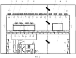
- the divider wall in the clean production area is configured to divide the clean production area into a production area 3 with a contamination source and a production area 4 without the contamination source.
- the divider wall in the upper technical interlayer is configured to divide the upper technical interlayer into an upper technical interlayer 1 with the contamination source and an upper technical interlayer 2 without the contamination source.
- the divider wall in the lower technical interlayer is configured to divide the lower technical interlayer into a lower technical interlayer 5 with the contamination source and a lower technical interlayer 6 without the contamination source.
- the divider wall disposed in the upper technical interlayer is double-layered to form a double-skin lane 9 in the upper technical interlayer, and the pressure regulation device assembly is configured to regulate an air pressure in double-skin lane 9 in the upper technical interlayer, such that during normal production of the clean room, the air pressure in double-skin lane 9 in the upper technical interlayer is higher than an air pressure in the adjacent upper technical interlayer 1 with the contamination source and an air pressure in the adjacent upper technical interlayer 2 without the contamination source;
- the double-skin lane 9 in the upper technical interlayer is disposed in the upper technical interlayer, and/or, the double-skin lane 11 in the lower technical interlayer is disposed in the lower technical interlayer.
- the pressure regulation device assembly may regulate the air pressure in double-skin lane 9 in the upper technical interlayer, such that during normal production of the clean room, the air pressure in double-skin lane 9 in the upper technical interlayer is higher than the air pressure in the upper technical interlayer 1 with the contamination source and the air pressure in the upper technical interlayer 2 without the contamination source.
- gas in double-skin lane 9 in the upper technical interlayer has a tendency to diffuse into the upper technical interlayer 1 with the contamination source and the upper technical interlayer 2 without the contamination source, such that gas with a contamination source in the upper technical interlayer 1 with the contamination source cannot enter the upper technical interlayer 2 without the contamination source through the double-skin lane 9 in the upper technical interlayer, thereby avoiding the contamination source from entering the production area 4 without the contamination source from the upper technical interlayer 2 without the contamination source.
- the pressure regulation device assembly is configured to regulate the air pressure in the double-skin lane 11 in the lower technical interlayer, such that during normal production of the clean room, the air pressure in the double-skin lane 11 in the lower technical interlayer is higher than the air pressure in the adjacent lower technical interlayer 5 with the contamination source and the air pressure in the adjacent lower technical interlayer 6 without the contamination source.
- the air pressure in the double-skin lane 11 in the lower technical interlayer is lower than that the air pressure in the adjacent lower technical interlayer 5 with the contamination source and the air pressure in the adjacent lower technical interlayer 6 without the contamination source.
- the gas in the lower technical interlayer 5 with the contamination source and the lower technical interlayer 6 without the contamination source has a tendency to move to the double-skin lane 11 in the lower technical interlayer or moves to the double-skin lane 11 in the lower technical interlayer, such that the gas with the contamination sources in the technical interlayers with the contamination sources cannot enter the technical interlayers without the contamination sources.
- double-skin lane 9 in the upper technical interlayer is formed in the upper technical interlayer, and the air pressure in double-skin lane in the upper technical interlayer is regulated through the pressure regulation device assembly; and/or the double-skin lane in the lower technical interlayer is formed in the lower technical interlayer, and the air pressure in the double-skin lane 11 in the lower technical interlayer is regulated through the pressure regulation device assembly, such that it is ensured that the gas with the contamination sources in the upper technical interlayer 1 with the contamination source and/or the lower technical interlayer 5 with the contamination source cannot enter the upper technical interlayer 2 without the contamination source and/or the lower technical interlayer 6 without the contamination source, thereby improving the yield of products in the production area 4 without the contamination source.
- the air pressure in double-skin lane 9 in the upper technical interlayer is higher than the air pressure in the upper technical interlayer 1 with the contamination source and the air pressure in the upper technical interlayer 2 without the contamination source
- the air pressure in the double-skin lane 11 in the lower technical interlayer is higher than the air pressure in the lower technical interlayer 5 with the contamination source and the air pressure in the lower technical interlayer 6 without the contamination source.
- Values of the pressure differences between the respective areas are as follows: +30 Pa in the production area 3 with the contamination source, +25 Pa in the lower technical interlayer 5 with the contamination source, -5 Pa in the upper technical interlayer 1 with the contamination source, +25 Pa in the production area 4 without the contamination source, +15 Pa in the lower technical interlayer 6 without the contamination source, -10 Pa the upper technical interlayer 2 without the contamination source, and +5 Pa in the double-skin lane 9 in the upper technical interlayer.
- double-skin lane 9 in the upper technical interlayer is formed in the upper technical interlayer
- the double-skin lane 11 in the lower technical interlayer is formed in the lower technical interlayer
- the air pressure in double-skin lane 9 in the upper technical interlayer is higher than the air pressure in the upper technical interlayer 1 with the contamination source and the air pressure in the upper technical interlayer 2 without the contamination source
- the air pressure in the double-skin lane 11 in the lower technical interlayer is lower than the air pressure in the lower technical interlayer 5 with the contamination source and the air pressure in the lower technical interlayer 6 without the contamination source.
- Values of the pressure differences between the respective areas are as follows: +30 Pa in the production area 3 with the contamination source, +25 Pa in the lower technical interlayer 5 with the contamination source, -5 Pa in the upper technical interlayer 1 with the contamination source, +25 Pa in the production area 4 without the contamination source, +15 Pa in the lower technical interlayer 6 without the contamination source, -10 Pa in the upper technical interlayer 2 without the contamination source is, +5 Pa in the double-skin lane 9 in the upper technical interlayer, and 0 Pa in the double-skin lane 11 in the lower technical interlayer.
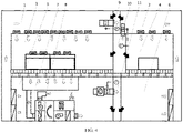
- the pressure regulation device assembly is also configured to regulate an air pressure in the double-skin lane in the clean production area, such that the air pressure in the double-skin lane 10 in the clean production area is higher than an air pressure in the production area 3 with the contamination source and an air pressure in the production area 4 without the contamination source.
- the double-skin lane 10 in the clean production area isolates the production area 3 with the contamination source from the production area 4 without the contamination source to form a buffer part.
- the air pressure in the double-skin lane 10 in the clean production area is higher than the air pressure in the adjacent production area 3 with the contamination source and the air pressure in the production area 4 without the contamination source under regulation of the pressure regulation device assembly, such that the contamination gas in the production area 3 with the contamination source cannot enter the production area 4 without the contamination source under the action of the air pressure.
- the pressure regulation device assembly includes a first pressure regulation device configured to simultaneously regulate the air pressure in the double-skin lane 10 in the clean production area and the air pressure in the double-skin lane 11 in the lower technical interlayer, and a second pressure regulation device configured to regulate the air pressure in double-skin lane 9 in the upper technical interlayer.
- the double-skin lane 11 in the lower technical interlayer communicates with the double-skin lane 10 in the clean production area, and the double-skin lane 10 in the clean production area is isolated from double-skin lane 9 in the upper technical interlayer, such that the air pressure in the double-skin lane 11 in the lower technical interlayer and the air pressure in the double-skin lane 10 in the clean production area are regulated through the first pressure regulation device, thereby improving the utilization rate of the first pressure regulation device, while double-skin lane 9 in the upper technical interlayer is regulated through the independent second pressure regulation device, such that the air pressure in double-skin lane 9 in the upper technical interlayer is different from the air pressure in the double-skin lane 10 in the clean production area.
- values of the pressure differences between the respective areas are as follows: +30 Pa in the production area 3 with the contamination source, +25 Pa in the lower technical interlayer 5 with the contamination source, -5 Pa in the upper technical interlayer 1 with the contamination source, +25 Pa in the production area 4 without the pollution area, +15 Pa in the lower technical interlayer 6 without the contamination source, -10 Pa in the upper technical interlayer 2 without the contamination source, +5 Pa double-skin lane 9 in the upper technical interlayer, and +35 Pa in the double-skin lane 10 in the clean production area and the double-skin lane 11 in the lower technical interlayer.
- the first pressure regulation device includes a first air supply device configured to cooperate with a fresh air unit so as to supply clean fresh air to the double-skin lane 11 in the lower technical interlayer and the double-skin lane 10 in the clean production area; and the second pressure regulation device includes a second air supply device configured to cooperate with the fresh air unit so as to supply clean fresh air to the double-skin lane 9 in the upper technical interlayer.
- the first air supply device supplies air in the double-skin lane 11 in the lower technical interlayer and the double-skin lane 10 in the clean production area, thereby ensuring that the air pressure of the double-skin lane 11 in the lower technical interlayer is higher than the air pressure in the adjacent two areas, the air pressure of the double-skin lane 10 in the clean production area is higher than the air pressure in the adjacent two areas, and a pressure difference is not less than 5 Pa.
- the arrangement of the second air supply device may make the air pressure in the upper technical interlayer higher than the air pressure in the adjacent two areas, and a pressure difference is not less than 5 Pa.
- a first differential pressure sensor is provided in the double-skin lane 11 in the lower technical interlayer or the double-skin lane 10 in the clean production area, and an air outlet pipe of the first air supply device is provided with a first regulation valve configured to regulate an opening degree according to a difference value detected by the first differential pressure sensor; and a second differential pressure sensor is provided in the double-skin lane 9 in the upper technical interlayer, and an air outlet pipe of the second air supply device is provided with a second regulation valve configured to regulate an opening degree according to a difference value detected by the second differential pressure sensor.
- the first differential pressure sensor may detect air pressure difference values between the double-skin lane 11 in the lower technical interlayer and the outside as well as between the double-skin lane 10 in the clean production area and the outside
- the second differential pressure sensor may detect an air pressure difference value between the double-skin lane 9 in the upper technical interlayer and the outside, such that a controller can control the first regulation valve and the second regulation valve individually, and then control an amount of air intake in the double-skin lane 11 in the lower technical interlayer and the double-skin lane 10 in the clean production area and an amount of air intake in double-skin lane 9 in the upper technical interlayer, thereby ensuring that the air pressure in double-skin lane 9 in the upper technical interlayer, the air pressure in the double-skin lane 11 in the lower technical interlayer and the air pressure in the double-skin lane 10 in the clean production area are within a preset range.
- the pressure regulation device assembly includes a first pressure regulation device configured to regulate the air pressure in double-skin lane 9 in the upper technical interlayer, a second pressure regulation device configured to regulate the air pressure in the double-skin lane 10 in the clean production area, and a third pressure regulation device configured to regulate the air pressure in the double-skin lane 11 in the lower technical interlayer.
- the double-skin lane 10 in the clean production area does not communicate with the double-skin lane 11 in the lower technical interlayer and double-skin lane 9 in the upper technical interlayer, such that the divider walls can be deployed at different positions in each interlayer for separation according to the deployment of devices in the clean room, and the renovation of an old clean room is facilitated.
- the first pressure regulation device, the second pressure regulation device and the third pressure regulation device are distributed in the double-skin lane 9 in the upper technical interlayer, the double-skin lane 10 in the clean production area and the double-skin lane 11 in the lower technical interlayer.
- the double-skin lane 9 in the upper technical interlayer, the double-skin lane 10 in the clean production area and the double-skin lane 11 in the lower technical interlayer may be controlled individually, such that the air pressure in double-skin lane 9 in the upper technical interlayer, the air pressure in the double-skin lane 10 in the clean production area and the air pressure in the double-skin lane 11 in the lower technical interlayer are more likely to reach a predetermined value.
- the first pressure regulation device includes a first air supply device configured to cooperate with the fresh air unit so as to supply clean fresh air to the double-skin lane 9 in the upper technical interlayer;
- the first air supply device and the second air supply device each may be connected with one fresh air unit separately, and the two fresh air units are utilized to provide fresh air for the first air supply device and the second air supply device.
- the first air supply device and the second air supply device may be connected with one fresh air unit, the fresh air unit is connected with at least two branch pipes, the first air supply device and the second air supply device are connected with the branch pipes respectively, and fresh air is provided for the first air supply device and the second air supply device through the branch pipes.
- the first air supply device and the second air supply device provide clean fresh air for the double-skin lane 9 in the upper technical interlayer and the double-skin lane 10 in the clean production area, and make the air pressure in the double-skin lane 9 in the upper technical interlayer higher not less than 5 Pa than the air pressure in the upper technical interlayer 1 with the contamination source and the air pressure in the upper technical interlayer 2 without the contamination source, such that the air pressure in the double-skin lane 10 in the clean production area is higher not less than 5 Pa than the air pressure in the production area 3 with the contamination source and the air pressure in the production area 4 without the contamination source; and the third pressure regulation device regulates the air pressure in the double-skin lane 11 in the lower technical interlayer to 0 Pa, such that the air pressure in the double-skin lane 11 in the lower technical interlayer is lower than the air pressure in the lower technical interlayer 5 with the contamination source and the lower technical interlayer 6 without the contamination source.
- the contamination gas generated in the production area 3 with the contamination source will not enter the production area 4 without the contamination source through the double-skin lane 10 in the clean production area, and also will not enter the lower technical interlayer 6 without the contamination source and/or the upper technical interlayer 2 without the contamination source via the lower technical interlayer 5 with the contamination source and/or the upper technical interlayer 1 with the contamination source.
- the clean room further includes a contamination source collection bellows 7 and a zeolite runner unit 8 communicating with the contamination source collection bellows 7; and the contamination source collection bellows 7 is configured to collect contaminants generated in the production area 3 with the contamination source, and make the collected contaminants enter the zeolite runner unit 8.
- the contamination source collection bellows 7 may collect the contamination gas generated in the production area 3 with the contamination source and make this part of gas enter in the zeolite runner unit 8, and the contamination gas is treated by the zeolite runner unit 8, such that an amount of the contamination gas in the lower technical interlayer 5 with the contamination source is reduced, and the probability of the gas with the contamination source entering the production area 4 without the contamination source is reduced.
- widths of the double-skin lane 9 in the upper technical interlayer, the double-skin lane 11 in the lower technical interlayer and the double-skin lane 10 in the clean production area are greater than or equal to 600 mm.
- the double-skin lane 11 in the lower technical interlayer and the double-skin lane 10 in the clean production area, and a speed of fresh air diffusion is generally 3-4 m/s, further preferably, the width of each double-skin lane is 600 mm in order to ensure that the effect of diffusing the fresh air in each double-skin lane is relatively good and the air pressure in each part of each double-skin lane is relatively uniform.
Landscapes
- Engineering & Computer Science (AREA)
- Architecture (AREA)
- Chemical & Material Sciences (AREA)
- Combustion & Propulsion (AREA)
- Mechanical Engineering (AREA)
- General Engineering & Computer Science (AREA)
- Civil Engineering (AREA)
- Structural Engineering (AREA)
- Ventilation (AREA)
- Separation Of Gases By Adsorption (AREA)
Applications Claiming Priority (2)
| Application Number | Priority Date | Filing Date | Title |
|---|---|---|---|
| CN201910736090.3A CN110439332B (zh) | 2019-08-09 | 2019-08-09 | 一种洁净室 |
| PCT/CN2020/104616 WO2021027528A1 (fr) | 2019-08-09 | 2020-07-24 | Salle propre susceptible d'empêcher la diffusion d'un polluant moléculaire gazeux |
Publications (2)
| Publication Number | Publication Date |
|---|---|
| EP4012139A1 true EP4012139A1 (fr) | 2022-06-15 |
| EP4012139A4 EP4012139A4 (fr) | 2022-09-28 |
Family
ID=68434331
Family Applications (1)
| Application Number | Title | Priority Date | Filing Date |
|---|---|---|---|
| EP20851748.2A Pending EP4012139A4 (fr) | 2019-08-09 | 2020-07-24 | Salle propre susceptible d'empêcher la diffusion d'un polluant moléculaire gazeux |
Country Status (4)
| Country | Link |
|---|---|
| EP (1) | EP4012139A4 (fr) |
| KR (1) | KR102758887B1 (fr) |
| CN (1) | CN110439332B (fr) |
| WO (1) | WO2021027528A1 (fr) |
Families Citing this family (8)
| Publication number | Priority date | Publication date | Assignee | Title |
|---|---|---|---|---|
| CN110439332B (zh) * | 2019-08-09 | 2024-09-03 | 世源科技工程有限公司 | 一种洁净室 |
| CN111457530A (zh) * | 2020-04-01 | 2020-07-28 | 北京联合大学 | 洁净室内移动污染源污染气隐藏式快速清除系统 |
| EP3912649B1 (fr) * | 2020-05-19 | 2023-10-25 | SEIWO Technik GmbH | Espace modulaire de protection, ainsi que passe-paquet pour un espace de protection |
| US12140342B2 (en) * | 2021-07-29 | 2024-11-12 | Taiwan Semiconductor Manufacturing Company Ltd. | Makeup air handling unit in semiconductor fabrication building and method for cleaning air using the same |
| CN113607765B (zh) * | 2021-08-03 | 2024-04-12 | 亚翔系统集成科技(苏州)股份有限公司 | 一种基于半导体生产线中不良产品的污染源查找方法 |
| CN114099194B (zh) * | 2021-10-25 | 2023-09-08 | 北京机械设备研究所 | 一种正压隔离舱 |
| CN115095187B (zh) * | 2022-03-24 | 2023-10-03 | 成都格力新晖医疗装备有限公司 | 移动实验室及其舱体机构 |
| CN116105251B (zh) * | 2023-03-14 | 2024-01-05 | 通威微电子有限公司 | 半导体厂房净化设备 |
Family Cites Families (21)
| Publication number | Priority date | Publication date | Assignee | Title |
|---|---|---|---|---|
| JPS625031A (ja) * | 1985-06-28 | 1987-01-12 | Kajima Corp | 部分的に清浄度の異なるクリ−ンル−ム |
| JP2811600B2 (ja) * | 1990-05-15 | 1998-10-15 | 須賀工業株式会社 | ヒートパイプ式熱交換器 |
| JPH05149591A (ja) * | 1991-04-30 | 1993-06-15 | Nippon Steel Corp | 半導体デバイスを製造するための製造設備及びクリーンルーム |
| JPH0694260A (ja) * | 1992-09-09 | 1994-04-05 | Nippon Steel Corp | 空調システム |
| JP3090088B2 (ja) * | 1997-02-07 | 2000-09-18 | 富士電機株式会社 | クリーンルームのファンフィルタユニット |
| US5922095A (en) * | 1997-03-20 | 1999-07-13 | Acoustiflo, Llc | Air handling system for buildings and clean rooms |
| US6574937B1 (en) * | 1999-09-07 | 2003-06-10 | Speedfam-Ipec Corporation | Clean room and method |
| CN1329696C (zh) * | 2005-08-22 | 2007-08-01 | 无锡华润微电子有限公司 | 洁净室的空气调节、净化系统 |
| JP4805013B2 (ja) * | 2006-05-16 | 2011-11-02 | エーザイ・アール・アンド・ディー・マネジメント株式会社 | クリーンルーム用給排気管理制御装置 |
| CN101503916B (zh) * | 2009-03-30 | 2011-03-23 | 云南白药集团股份有限公司 | 一种模块化厂房结构 |
| CN102889249B (zh) * | 2012-10-30 | 2015-07-15 | 深圳市华星光电技术有限公司 | 一种风机滤器单元和无尘室空气净化系统 |
| CN204402090U (zh) * | 2014-10-29 | 2015-06-17 | 中国医药集团重庆医药设计院 | 避免人流、物流交叉的生物医药厂房结构 |
| CN105987433B (zh) * | 2014-12-25 | 2019-04-09 | 世源科技工程有限公司 | 空气处理系统 |
| CN105135566B (zh) * | 2015-09-09 | 2017-12-26 | 同济大学 | 一种基于空气定向流动原理的污染物隔断系统及其使用方法 |
| CN105289203A (zh) * | 2015-11-10 | 2016-02-03 | 信利(惠州)智能显示有限公司 | 一种气体分子污染物热处理单元 |
| CN206385856U (zh) * | 2016-06-15 | 2017-08-08 | 高海 | 低集成度成套性分析检测基础装备实验室建筑模块 |
| CN106245944B (zh) * | 2016-06-15 | 2018-08-17 | 高海 | 分析检测基础装备实验室建筑模块 |
| US10663189B2 (en) * | 2016-11-19 | 2020-05-26 | Harris Environmental Systems, Inc. | Environmental room with reduced energy consumption |
| CN109253520B (zh) * | 2018-10-31 | 2024-05-03 | 石家庄学院 | 洁净区通风系统及压差调节方法 |
| CN110439332B (zh) * | 2019-08-09 | 2024-09-03 | 世源科技工程有限公司 | 一种洁净室 |
| CN210713992U (zh) * | 2019-08-09 | 2020-06-09 | 世源科技工程有限公司 | 一种洁净室 |
-
2019
- 2019-08-09 CN CN201910736090.3A patent/CN110439332B/zh active Active
-
2020
- 2020-07-24 EP EP20851748.2A patent/EP4012139A4/fr active Pending
- 2020-07-24 KR KR1020227007036A patent/KR102758887B1/ko active Active
- 2020-07-24 WO PCT/CN2020/104616 patent/WO2021027528A1/fr not_active Ceased
Also Published As
| Publication number | Publication date |
|---|---|
| KR20220035264A (ko) | 2022-03-21 |
| EP4012139A4 (fr) | 2022-09-28 |
| WO2021027528A1 (fr) | 2021-02-18 |
| CN110439332B (zh) | 2024-09-03 |
| CN110439332A (zh) | 2019-11-12 |
| KR102758887B1 (ko) | 2025-01-23 |
Similar Documents
| Publication | Publication Date | Title |
|---|---|---|
| KR102758887B1 (ko) | 기체 분자 오염 물질 확산을 억제하기 위한 클린룸 | |
| KR100250354B1 (ko) | 클린 룸 | |
| CN1119040A (zh) | 环境控制系统 | |
| EP2889088A2 (fr) | Dispositif de traitement de gaz de carneau | |
| CN102165566B (zh) | 表面处理装置 | |
| CN1177709A (zh) | 净化室 | |
| CN210713992U (zh) | 一种洁净室 | |
| CN102908867A (zh) | 一种优化气流分布的活性焦烟气净化装置 | |
| SE515895C2 (sv) | Anordning, förfarande och system för luftfiltrering | |
| CN103939996B (zh) | 能净化空气中粉尘和细菌并提供富氧新风的系统及方法 | |
| CN106556085A (zh) | 无尘室车间及无尘室车间的气流调节方法 | |
| CN103752114A (zh) | 模块化水幕光氧组合废气净化器 | |
| KR101044315B1 (ko) | 반도체장치 제조 설비 및 운용 방법 | |
| CN110469160B (zh) | 一种具有二次加湿系统的洁净室布置结构及洁净生产厂房 | |
| JPH09101051A (ja) | クリーンルーム内への空気導入方法、クリーンルーム、局所設備内への空気導入方法、および局所設備 | |
| CN213841205U (zh) | 一种设有分区压差的净化车间 | |
| KR20140121313A (ko) | 공정 가스 정화장치를 구비한 누출가스 자동 제어 시스템 | |
| CN117556723A (zh) | 一种基于动网格技术的洁净室内防交叉污染控制方法 | |
| CN111305612A (zh) | 一种半导体厂房洁净室 | |
| JP2580375B2 (ja) | クリ―ンル―ム | |
| CN223996137U (zh) | 一种零泄漏的洁净工作台 | |
| JPH08247512A (ja) | クリーンルーム | |
| TWM663927U (zh) | 無塵室之空氣處理系統 | |
| CN221144500U (zh) | 一种隧道空气净化系统 | |
| JP2543780Y2 (ja) | クリーンルームのファンフイルタユニット |
Legal Events
| Date | Code | Title | Description |
|---|---|---|---|
| STAA | Information on the status of an ep patent application or granted ep patent |
Free format text: STATUS: THE INTERNATIONAL PUBLICATION HAS BEEN MADE |
|
| PUAI | Public reference made under article 153(3) epc to a published international application that has entered the european phase |
Free format text: ORIGINAL CODE: 0009012 |
|
| STAA | Information on the status of an ep patent application or granted ep patent |
Free format text: STATUS: REQUEST FOR EXAMINATION WAS MADE |
|
| 17P | Request for examination filed |
Effective date: 20220203 |
|
| AK | Designated contracting states |
Kind code of ref document: A1 Designated state(s): AL AT BE BG CH CY CZ DE DK EE ES FI FR GB GR HR HU IE IS IT LI LT LU LV MC MK MT NL NO PL PT RO RS SE SI SK SM TR |
|
| A4 | Supplementary search report drawn up and despatched |
Effective date: 20220825 |
|
| RIC1 | Information provided on ipc code assigned before grant |
Ipc: F24F 11/00 20180101ALN20220819BHEP Ipc: F24F 13/02 20060101ALI20220819BHEP Ipc: F24F 7/10 20060101ALI20220819BHEP Ipc: F24F 11/89 20180101ALI20220819BHEP Ipc: F24F 13/00 20060101ALI20220819BHEP Ipc: F24F 3/16 20210101ALI20220819BHEP Ipc: E04H 5/02 20060101AFI20220819BHEP |
|
| DAV | Request for validation of the european patent (deleted) | ||
| DAX | Request for extension of the european patent (deleted) | ||
| STAA | Information on the status of an ep patent application or granted ep patent |
Free format text: STATUS: EXAMINATION IS IN PROGRESS |
|
| 17Q | First examination report despatched |
Effective date: 20241021 |