EP4010977B1 - Verfahren zum ermitteln einer rotorposition eines elektromotors eines elektrowerkzeugs und elektrowerkzeug - Google Patents
Verfahren zum ermitteln einer rotorposition eines elektromotors eines elektrowerkzeugs und elektrowerkzeug Download PDFInfo
- Publication number
- EP4010977B1 EP4010977B1 EP20743690.8A EP20743690A EP4010977B1 EP 4010977 B1 EP4010977 B1 EP 4010977B1 EP 20743690 A EP20743690 A EP 20743690A EP 4010977 B1 EP4010977 B1 EP 4010977B1
- Authority
- EP
- European Patent Office
- Prior art keywords
- electric motor
- motor current
- power tool
- rotor position
- threshold value
- Prior art date
- Legal status (The legal status is an assumption and is not a legal conclusion. Google has not performed a legal analysis and makes no representation as to the accuracy of the status listed.)
- Active
Links
Images


Classifications
-
- H—ELECTRICITY
- H02—GENERATION; CONVERSION OR DISTRIBUTION OF ELECTRIC POWER
- H02P—CONTROL OR REGULATION OF ELECTRIC MOTORS, ELECTRIC GENERATORS OR DYNAMO-ELECTRIC CONVERTERS; CONTROLLING TRANSFORMERS, REACTORS OR CHOKE COILS
- H02P6/00—Arrangements for controlling synchronous motors or other dynamo-electric motors using electronic commutation dependent on the rotor position; Electronic commutators therefor
- H02P6/14—Electronic commutators
- H02P6/16—Circuit arrangements for detecting position
- H02P6/18—Circuit arrangements for detecting position without separate position detecting elements
- H02P6/185—Circuit arrangements for detecting position without separate position detecting elements using inductance sensing, e.g. pulse excitation
-
- H—ELECTRICITY
- H02—GENERATION; CONVERSION OR DISTRIBUTION OF ELECTRIC POWER
- H02P—CONTROL OR REGULATION OF ELECTRIC MOTORS, ELECTRIC GENERATORS OR DYNAMO-ELECTRIC CONVERTERS; CONTROLLING TRANSFORMERS, REACTORS OR CHOKE COILS
- H02P23/00—Arrangements or methods for the control of AC motors characterised by a control method other than vector control
- H02P23/14—Estimation or adaptation of motor parameters, e.g. rotor time constant, flux, speed, current or voltage
-
- B—PERFORMING OPERATIONS; TRANSPORTING
- B25—HAND TOOLS; PORTABLE POWER-DRIVEN TOOLS; MANIPULATORS
- B25B—TOOLS OR BENCH DEVICES NOT OTHERWISE PROVIDED FOR, FOR FASTENING, CONNECTING, DISENGAGING OR HOLDING
- B25B21/00—Portable power-driven screw or nut setting or loosening tools; Attachments for drilling apparatus serving the same purpose
-
- B—PERFORMING OPERATIONS; TRANSPORTING
- B25—HAND TOOLS; PORTABLE POWER-DRIVEN TOOLS; MANIPULATORS
- B25F—COMBINATION OR MULTI-PURPOSE TOOLS NOT OTHERWISE PROVIDED FOR; DETAILS OR COMPONENTS OF PORTABLE POWER-DRIVEN TOOLS NOT PARTICULARLY RELATED TO THE OPERATIONS PERFORMED AND NOT OTHERWISE PROVIDED FOR
- B25F5/00—Details or components of portable power-driven tools not particularly related to the operations performed and not otherwise provided for
-
- H—ELECTRICITY
- H02—GENERATION; CONVERSION OR DISTRIBUTION OF ELECTRIC POWER
- H02P—CONTROL OR REGULATION OF ELECTRIC MOTORS, ELECTRIC GENERATORS OR DYNAMO-ELECTRIC CONVERTERS; CONTROLLING TRANSFORMERS, REACTORS OR CHOKE COILS
- H02P2203/00—Indexing scheme relating to controlling arrangements characterised by the means for detecting the position of the rotor
- H02P2203/09—Motor speed determination based on the current and/or voltage without using a tachogenerator or a physical encoder
Definitions
- the invention relates to a method for determining a rotor position of an electric motor of a power tool, in particular an electric screwing tool.
- the EP0579694B1 , EP1051801B1 , EP1746718B1 and DE102016222754A1 each describe methods for detecting a rotor position based on an electric motor current.
- the methods are based on a dependency of a winding inductance of the electric motor on the rotor position. A change in the rotor position leads to a change in the winding inductance, which in turn leads to a change in the electric motor current.
- the US 2017/310256 A1 describes a method for controlling a brushless permanent magnet motor comprising sequentially energizing and freewheeling a phase winding of the motor.
- the phase winding is operated in freewheeling when the phase current exceeds an upper threshold.
- the method further comprises measuring a parameter corresponding to either the magnitude of the phase current during or at the end of freewheeling when the phase winding is subjected to freewheeling for a fixed period of time, or the time interval during freewheeling or during excitation when the phase winding is in freewheeling until the phase current falls below the lower threshold.
- the measured parameter is then compared to a saturation threshold and the rotor is determined to be at a predetermined position. In response to the rotor being determined to be at the predetermined position, the phase winding is commutated after one commutation period has elapsed.
- the DE 10 2009 003295 A1 describes a device for estimating rotor position for brushless motors.
- the device can be used as a starting system for brushless motors.
- the device applies voltages to the coils respectively.
- the device counts a voltage application time period until the current value reaches a current threshold. Since a coil indicating a rotor stop position tends to become magnetically saturated, the device estimates the rotor stop position based on the voltage application time period. Then, the device begins a switching sequence based on the rotor stop position.
- the DE 10 2018 201052 A1 describes a method for controlling a rotational speed of an electric motor of a screwing tool, wherein after activation of the screwing tool, a current signal for controlling the screwing tool is increased over time in a start-up phase, wherein during the start-up phase it is checked whether an operating parameter of the electric motor is greater than a comparison value, wherein after the comparison value is exceeded, the current signal is reduced until a second operating state of the electric motor is reached.
- Detecting the rotor position based on the electric motor current should also be referred to as sensorless detection of the rotor position.
- An object of the invention is to provide a method which enables a reliable determination of the rotor position in an efficient manner.
- the object is achieved by a method according to claim 1.
- the detection of the rotor position is determined on the basis of an electric motor current - i.e., in particular, it is carried out without sensors - there is no need for corresponding sensors, such as signal transmitters, to detect the rotor position.
- the power tool expediently does not include any sensors for detecting, in particular directly detecting, the rotor position. In particular, no sensors for detecting, in particular directly detecting, the rotor position are used within the scope of the method.
- the electric motor current is expediently used as an indicator of the magnetic saturation of the electric motor.
- the dependence of the winding inductance on the rotor position is usually very low or no longer present.
- the electric motor is magnetically saturated, it is therefore usually no longer possible to reliably determine the rotor position from the electric motor current (which depends on the winding inductance).
- the electric motor is dimensioned so large that no magnetic saturation occurs during normal operation, thus avoiding the detection of the rotor position based on the electric motor current being impaired by magnetic saturation.
- the electric motor is operated in temporally successive, in particular non-overlapping operating phases.
- the operating phases comprise a position determination phase in which the rotor position is determined and in which the first electric motor current is less than the threshold value.
- the operating phases further comprise a torque phase. In the torque phase, the Rotor position not determined and expediently in the torque phase the first electric motor current is greater than the threshold value.
- the power tool uses the rotor position determined in the position determination phase to control the electric motor.
- the invention further relates to a power tool according to claim 13.
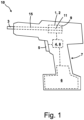
- the Figure 1 shows a power tool 10 according to an exemplary embodiment.
- the power tool 10 is designed here as an electric screwdriver, in particular as a cordless screwdriver.
- the power tool 10 can be designed as another power tool, in particular as a power tool with a rotating tool.
- the power tool can be designed, for example, as a saw, Grinder, drill and/or milling machine.
- the power tool 10 is in particular a hand-held power tool.
- the power tool 10 can be a stationary or semi-stationary power tool.
- the power tool 10 comprises an electric motor 2.
- the power tool 10 is designed to check whether a first electric motor current I1 is below a threshold value SW.
- An exemplary temporal profile of the electric motor current I1 is shown together with the threshold value SW in the Figure 5 shown.
- the power tool 10 is designed to determine a rotor position of the electric motor 2 on the basis of the first electric motor current I1 and/or a second electric motor current in response to the test showing that the first electric motor current I1 is below the threshold value SW.
- the second electric motor current comprises, for example, one or more of the Figure 3 shown branch currents IZ1, IZ2, IZ3 and/or the Figure 3 shown total current IS.
- the power tool 10 is in particular designed to carry out the determination of the rotor position on the basis of the first and/or second electric motor current in response to the fact that the test shows that the electric motor current I1 is below the threshold value SW.
- the power tool 10 is designed not to carry out a determination of the rotor position on the basis of the first and/or second electric motor current in response to the fact that the test shows that the electric motor current I1 is above the threshold value SW.
- the power tool 10 is designed to carry out the determination of the rotor position on the basis of the first and/or second electric motor current only if the test shows that the electric motor current I1 is below the threshold value SW.
- the first electric motor current I1 serves as an indicator for the magnetic saturation of the electric motor 2.
- the power tool 10 comprises an electric drive 1.
- the electric drive 1 comprises the electric motor 2.
- the electric drive 1 further comprises a gear (not shown in the figures).
- the electric motor 2 is preferably designed as a brushless direct current motor.
- the electric motor 2 is in particular a three-phase synchronous motor with excitation by permanent magnets.
- the electric motor 2 is expediently an EC motor (electronically commutated motor).
- the power tool 10 further comprises a tool 3, for example a screwing tool, which can be driven by the electric motor 2.
- a tool 3 can be set in rotation by the electric motor 2.
- the tool 3 is coupled to the electric motor 2 via a shaft 15 (and/or the optionally present gear).
- the power tool 10 expediently further comprises a control device 4 and an operating device 5.
- the power tool 10 further comprises an energy storage device 6, for example a battery.
- the control device 4 expediently comprises a computer unit, for example a microcontroller.
- the control device 4 serves in particular to carry out the aforementioned check as to whether the first electric motor current I1 is below the threshold value SW and/or to determine the rotor position on the basis of the first and/or second electric motor current.
- the control device 4 expediently comprises a control circuit 8 for providing the control voltages for the electric motor 2. An exemplary embodiment of a control circuit 8 is shown in the Figure 3 shown.
- the operating device 5 comprises, for example, a button, in particular a trigger button.
- a user can expediently control the drive of the tool 3 by the electric motor 2 via the operating device 5, in particular the speed and/or torque at which the tool 3 is driven.
- the control device 4 is expediently designed to detect an actuation of the operating device 5 and to control the electric motor 2 in accordance with the actuation.
- the energy for operating the power tool 10, in particular the control device 4 and/or the electric motor 2, is expediently provided by the energy storage device 6.
- the power tool 10 comprises, by way of example, a handle 7 with which the power tool 10 can be gripped and carried by a user, in particular with one hand.
- the power tool 10 comprises a housing in which the electric drive 1, the control device 4 and/or the energy storage device 6 are arranged.
- the operating device 5 is preferably arranged on the outside of the housing.
- the handle 7 expediently forms part of the housing.
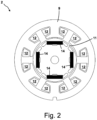
- the electric motor 2 comprises a stator 9 and a rotor 11.
- the stator 9 comprises a plurality of windings 12 which are arranged distributed around the axis of rotation of the rotor 11.
- the rotor 11 comprises a plurality of permanent magnets 14 which are arranged distributed around the axis of rotation of the rotor 11.
- the rotor 11 is preferably not designed to be radially symmetrical, in particular with regard to its magnetic properties. Depending on the rotor position of the rotor 11, the influence of the rotor on the inductances of the windings 12 changes. The inductances of the windings 12 are expediently dependent on the rotor position of the rotor 11.
- the term rotor position refers in particular to the rotational position of the rotor 11 with regard to its axis of rotation. According to an alternative embodiment, the rotor 11 is designed to be radially symmetrical.
- the windings 12 are energized via the control circuit 7 in such a way that a rotating field is provided which rotates about the axis of rotation of the rotor 11 and which, through interaction with the permanent magnets 14, drives the rotor 11 to rotate about its axis of rotation.
- the stator 9 and/or the rotor 11 expediently comprise magnetizable, in particular ferromagnetic, material, for example iron. From a certain current strength of the currents flowing through the windings 12, the magnetizable material goes into magnetic saturation. In the case of magnetic saturation, the dependence of the inductances of the windings 12 - and thus of the currents flowing through the windings 12 - on the rotor position is reduced and/or eliminated.
- the magnetic saturation of the electric motor 2, in particular of the mentioned magnetizable material of the stator 9 and/or rotor 11, is expediently indicated by the threshold value SW.
- the threshold value SW expediently corresponds to a current strength of the first electric motor current I1 at which a magnetic saturation of the electric motor 2, in particular of the mentioned magnetizable material of the stator 9 and/or rotor 11, is present.
- the threshold value SW is expediently determined in advance and is stored in the power tool 10, in particular in the control device 4.
- the first electric motor current I1 expediently comprises one, several or all currents flowing through the windings 12.
- the first electric motor current I1 is the sum of the currents flowing through the windings 12.
- the first electric motor current I1 is the sum of the currents flowing into the windings 12 or out of the windings 12.
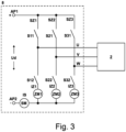
- the control circuit 8 is expediently designed as an inverter.
- the control circuit 8 serves in particular to provide several control signals for controlling the electric motor 2, in particular the windings 12.
- the control circuit 8 provides three control signals.
- the control circuit 8 has, as an example, a first output U for providing a first control signal, a second output V for providing a second control signal and a third output W for providing a third control signal.
- the control circuit 8 expediently provides the control signals on the basis of a supply voltage Ud applied between two connection points AP1, AP2.
- the supply voltage Ud is expediently a direct voltage.
- the three control signals can also be referred to as phases.
- the control signals are preferably voltage signals.
- the control circuit 8 comprises, for example, a respective circuit branch SZ1, SZ2, SZ3 for each of the outputs U, V, W.
- the circuit branches SZ1, SZ2, SZ3 are each connected between the two connection points AP1, AP2.
- the circuit branches SZ1, SZ2, SZ3 are each designed as a half-bridge.
- Each circuit branch SZ1, SZ2, SZ3 expediently comprises two switches - a first switch S11, S21, S31 and a second switch S12, S22, S32.
- the respective output U, V, W can be connected to the first Connect connection point AP1 and via the second switch S12, S22, S33 to the second connection point AP2.
- alternating signals in particular alternating signals that are phase-shifted with respect to one another, can expediently be provided as the control signals in order to drive the rotor 11.
- the power tool 10 is designed to detect the first electric motor current I1 and/or the second electric motor current.
- the first electric motor current I1 and/or the second electric motor current are currents that flow through one, several or all of the windings 12 of the electric motor 2.
- the first electric motor current I1 and the second electric motor current can be the same current or can be different currents.
- the first electric motor current I1 is the total current that flows through the windings 12. This current is recorded as the total current IS that flows into the second connection point AP2. Alternatively or additionally, the total current can also be recorded as a total current IS that flows into or out of the first connection point AP1.
- the power tool 10, in particular the control circuit 8, comprises, by way of example, a total current measuring unit SM for detecting the total current IS.
- the total current measuring unit SM is, by way of example, connected between the second connection point AP2 and the second switches S12, S22, S32.
- the first electric motor current I1 can further comprise one, several or all of the branch currents IZ1, IZ2, IZ3 flowing in the circuit branches SZ1, SZ2, SZ3.
- the power tool 10 is expediently designed to compare one, several or all branch currents IZ1, IZ2, IZ3 with the threshold value SW and to carry out the determination of the rotor position in response to each compared branch current IZ1, IZ2, IZ3 being smaller than the threshold value SW.
- the power tool 10, in particular the control circuit 8, comprises, by way of example, a plurality of branch current measuring units ZM1, ZM2, ZM3 for detecting the respective branch currents IZ1, IZ2, IZ3.
- the branch current measuring units ZM1, ZM2, ZM3 are each connected in a respective circuit branch SZ1, SZ2, SZ3.
- branch current measuring unit ZM1, ZM2, ZM3 is present for each circuit branch SZ1, SZ2, SZ3, there can also be fewer branch current measuring units than circuit branches. For example, there can be no branch current measuring unit for a circuit branch.
- the branch current of this circuit branch is then expediently calculated by the power tool 10, in particular on the basis of the other branch currents and the total current.
- the following describes the determination of the rotor position based on the first and/or second electric motor current.
- the power tool 10 is expediently designed to apply a test signal to the electric motor 2 and to determine the rotor position on the basis of the reaction of the first electric motor current and/or second electric motor current to the test signal. Expediently, the rotor 11 is not driven by the application of the test signal.
- the test signal expediently comprises a sequence of Switching states and/or voltage values for the outputs U, V, W, which are achieved by controlling the first and second switches S11, S21, S31, S12, S22, S32.
- test signals for controlling the electric motor 2 for the purpose of determining the rotor position are described in the prior art mentioned at the beginning.
- test signals from the so-called "Inform method” are known.
- the power tool 10 is expediently designed to control the electric motor 2 with a test signal according to the Inform method.
- the first and/or second electric motor current can change.
- the power tool 10 is designed to detect the first and/or second electric motor current and to determine the rotor position on the basis thereof.
- the power tool 10 expediently detects the branch currents IZ1, IZ2, IZ3 as the second electric motor current and determines the rotor position on the basis of the branch currents IZ1, IZ2, IZ3, in particular on the basis of the time profile and/or certain signal characteristics of the branch currents IZ1, IZ2, IZ3.
- the power tool 10 detects two of the branch currents IZ1, IZ2, IZ3 as the second electric motor current and determines the rotor position on the basis of the two detected branch currents, in particular on the basis of the time course and/or certain signal characteristics of the two detected branch currents.
- the power tool 10 detects the total current IS as the second electric motor current and determines the rotor position on the basis of the total current IS, in particular on the basis of the time course and/or certain signal characteristics of the total current IS.
- the power tool 10 is in particular designed to carry out a control, in particular a commutation, of the electric motor 2 on the basis of the determined rotor position.
- the power tool 10 is in particular designed to carry out a sensorless commutation of the electric motor 2 using the determined rotor position.
- the power tool 10 is designed to provide the control signals provided at the outputs U, V, W on the basis of the determined rotor position.
- the power tool 10 expediently provides the control signals provided at the outputs U, V, W on the basis of the determined rotor position and on the basis of a user input entered by the operating device 5, for example a requested speed and/or a requested torque.
- the power tool 10 is expediently designed to continue the control of the electric motor 2, in particular the commutation, on the basis of the last determined rotor position until a new determined rotor position is available. If, for example, the first electric motor current I1 is above the threshold value SW and the power tool 10 cannot determine the rotor position, the power tool 10 continues to use the last determined rotor position at this time to control the electric motor 2.
- the power tool 10 expediently rotates the rotor 11 electrically by 90 degrees by controlling the electric motor 2 on the basis of a determined first rotor position and then, if no new rotor position of the rotor 11 has been determined, continues the control on the basis of the first rotor position.
- a rotation of 90 degrees electrically corresponds, for example, to a rotation of the rotor by 45 degrees mechanically with two pole pairs and 30 degrees mechanically with three pole pairs.
- the control procedure is an embodiment of a method for determining the rotor position of the electric motor 2 of the power tool 10.
- the control procedure AP is expediently carried out by the power tool 10, in particular by the control device 4.
- the control procedure AP begins with an optional step S1, in which the rotor position is determined on the basis of the first and/or second electric motor current, expediently in a state in which the rotor 11 is not yet driven and expediently does not move.
- the optional step S2 carried out in which the electric motor 2 is started; that is, in particular, the first electric motor current I1 is increased to such an extent that the rotor 11 is driven and expediently set in motion.
- step S3 in which the electric motor 2 is controlled, in particular the windings 12 are energized, in order to generate a torque that is applied to the tool 3.
- the windings 12 can be energized to such an extent that the first electric motor current I1 rises above the threshold value SW or that the first electric motor current I1 remains below the threshold value SW.
- step S3 the electric motor 2 is controlled on the basis of the rotor position determined in a previous step (for example S2, S5 or S8).
- step S4 it is checked whether the first electric motor current I1 is less than the threshold value SW. If the check shows that the first electric motor current I1 is less than the threshold value SW, the control procedure continues with step S5, in which the rotor position is determined on the basis of the first and/or second electric motor current.
- the electric motor 2, in particular the windings 12, are expediently controlled with the test signal.
- the branch currents IZ1, IZ2, IZ3 resulting in response to the test signal are expediently recorded and based on these branch currents IZ1, IZ2, IZ3 determines the rotor position.
- the control procedure AP then conveniently returns to step S3.
- the power tool 10 is expediently designed not to determine the rotor position on the basis of the first and/or second electric motor current in response to the test showing that the electric motor current I1 is above the threshold value SW.
- the power tool 10 is designed not to control the electric motor 2 with the test signal and/or not to detect the branch currents IZ1, IZ2, IZ3 resulting in response to the test signal and/or not to determine the rotor positions on the basis of these branch currents IZ1, IZ2, IZ3 in response to the test signal if the test shows that the electric motor current I1 is above the threshold value SW. Accordingly, no determination of the rotor position on the basis of the first and/or second electric motor current is carried out in steps S6 and S7.
- the power tool 10 is expediently designed to reduce the electric motor current I1 until the electric motor current I1 is below the threshold value SW in response to the test showing that the electric motor current I1 is above the threshold value SW.
- this is done by way of example by stopping the control of the electric motor 2 in step S6.
- the motor phases, in particular the control signals, of the electric motor 2 are switched off.
- the control circuit 8 is configured so that switched so that the currents flowing in the windings 12 are reduced. For example, all first switches S11, S21, S31 are opened (i.e. set to "non-conductive") and all second switches S21, S22, S32 are closed (i.e. set to "conductive"). Alternatively, all first switches S11, S21, S31 are closed and all second switches S21, S22, S32 are opened.
- step S7 the system waits, for example while the control of the electric motor 2 is still stopped, until the first electric motor current I1 falls below the threshold value SW.
- the power tool 10 is expediently designed to determine the rotor position on the basis of the first and/or second electric motor current after the reduction of the first electric motor current I1 below the threshold value SW.
- the determination of the rotor position takes place, for example, in step S8.
- the control procedure then continues with step S3.
- the power tool is expediently designed to increase the first electric motor current I1 above the threshold value SW after determining the rotor position, for example in step S3.
- the Figure 5 shows a temporal progression of the first electric motor current I1 together with successive operating phases of the power tool 10.
- the operating phases include, for example, Position determination phases PP1, PP2, PP3, torque phases DP1, DP2 and reduction phases RP1, RP2.
- the operating phases are carried out one after the other in the following order: position determination phase, torque phase, reduction phase. It is advisable to repeat the operating phases in the order mentioned several times, in particular continuously.
- the operating phases are carried out one after the other in the following order: first position determination phase PP1, first torque phase DP1, first reduction phase RP1, second position determination phase PP2, second torque phase DP2, second reduction phase RP2, third position determination phase PP3.
- the power tool 10 is expediently designed to begin with the first position determination phase PP1.
- the first electric motor current I1 is below the threshold value SW.
- the power tool 10 is designed to determine the rotor position on the basis of the first and/or second electric motor current during the first position determination phase PP1.
- step S2 In the first position determination phase PP1, in particular step S2 and optionally step S1 are carried out beforehand.
- the power tool 10 is expediently designed to carry out the first torque phase DP1 after the position determination phase and to increase the first electric motor current I1 above the threshold value SW during the first torque phase DP1.
- the power tool 10 is expediently designed not to carry out any Determine the rotor position based on the first and/or second electric motor current.
- steps S3 and S4 are carried out in particular.
- the power tool 10 expediently uses the rotor position determined in the first position determination phase PP1 to control the electric motor 2 in the first torque phase DP1.
- the power tool 10 is expediently designed to carry out the first reduction phase RP1 after the first torque phase DP1 and to reduce the first electric motor current I1 below the threshold value SW during the first reduction phase RP1.
- steps S6 and S7 are carried out in particular.
- the power tool 10 then expediently continues with the second position determination phase PP2, in particular if the power tool 10 has determined during a test that the first electric motor current I1 is less than the threshold value SW.
- the power tool 10 carries out the second position determination phase PP2 like the first position determination phase PP1 and then continues with the subsequent operating phases in the manner explained above.
Landscapes
- Engineering & Computer Science (AREA)
- Mechanical Engineering (AREA)
- Power Engineering (AREA)
- Control Of Motors That Do Not Use Commutators (AREA)
Description
- Die Erfindung betrifft ein Verfahren zum Ermitteln einer Rotorposition eines Elektromotors eines Elektrowerkzeugs, insbesondere eines Elektro-Schraubwerkzeugs.
- Die
EP0579694B1 ,EP1051801B1 ,EP1746718B1 undDE102016222754A1 beschreiben jeweils Verfahren zur Erfassung einer Rotorposition auf Basis eines Elektromotor-Stroms. Die Verfahren basieren auf einer Abhängigkeit einer Wicklungsinduktivität des Elektromotors von der Rotorposition. Eine Änderung der Rotorposition führt zu einer Änderung der Wicklungsinduktivität, die wiederum zu einer Änderung des Elektromotor-Stroms führt. - Die
US 2017/310256 A1 beschreibt ein Verfahren zur Steuerung eines bürstenlosen Permanentmagnetmotors, das eine sequentielle Erregung und den Freilauf einer Phasenwicklung des Motors umfasst. Die Phasenwicklung wird im Freilauf betrieben, wenn der Phasenstrom einen oberen Schwellenwert überschreitet. Das Verfahren umfasst ferner ein Messen eines Parameters, der entweder der Magnitude des Phasenstroms während oder am Ende des Freilaufs entspricht, wenn die Phasenwicklung dem Freilauf für eine feste Zeitperiode unterzogen wird, oder dem Zeitintervall während des Freilaufs oder während einer Anregung, wenn sich die Phasenwicklung im Freilauf befindet bis der Phasenstrom unter den unteren Schwellenwert fällt. Der gemessene Parameter wird dann mit einem Sättigungsschwellenwert verglichen, und der Rotor wird als an einer vorbestimmten Position befindlich bestimmt. In Ansprechen darauf, dass bestimmt wird, dass sich der Rotor an der vorbestimmten Position befindet, wird die Phasenwicklung kommutiert, nachdem eine Kommutationsperiode abgelaufen ist. - Die
DE 10 2009 003295 A1 beschreibt ein Gerät zum Schätzen der Rotorposition für bürstenlose Motoren. Das Gerät kann als Startsystem für bürstenlose Motoren verwendet werden. Das Gerät legt Spannungen an die Spulen jeweils an. In jeder Anlegezeitdauer zählt das Gerät eine Spannungsanlegezeitdauer, bis der Stromwert einen Stromschwellwert erreicht. Da eine Spule, die eine Rotorstoppposition angibt, dazu neigt, magnetisch gesättigt zu werden, schätzt das Gerät die Rotorstoppposition auf der Grundlage der Spannungsanlegezeitdauer. Dann beginnt das Gerät eine Schaltabfolge auf der Grundlage der Rotorstoppposition. - Die
DE 10 2018 201052 A1 beschreibt ein Verfahren zum Steuern einer Drehzahl eines Elektromotors eines Schraubwerkzeuges, wobei nach einer Aktivierung des Schraubwerkzeuges ein Stromsignal zum Steuern des Schraubwerkzeuges in einer Startphase mit der Zeit erhöht wird, wobei während der Startphase überprüft wird, ob ein Betriebsparameter des Elektromotors größer als ein Vergleichswert ist, wobei nach Überschreiten des Vergleichswertes das Stromsignal so lange reduziert wird, bis ein zweiter Betriebszustand des Elektromotors erreicht ist. - Eine Erfassung der Rotorposition auf Basis des Elektromotor-Stroms soll auch als sensorlose Erfassung der Rotorposition bezeichnet werden.
- Eine Aufgabe der Erfindung besteht darin, ein Verfahren bereitzustellen, mit dem in effizienter Weise eine zuverlässige Ermittlung der Rotorposition ermöglicht wird.
- Die Aufgabe wird gelöst durch ein Verfahren gemäß Anspruch 1.
- Dadurch, dass die Erfassung der Rotorposition auf Basis eines Elektromotor-Stroms ermittelt wird - also insbesondere sensorlos erfolgt - kann auf eine entsprechende Sensorik, beispielsweise Signalgeber, zur Erfassung der Rotorposition verzichtet werden. Zweckmäßigerweise umfasst das Elektrowerkzeug keine Sensoren zur Erfassung, insbesondere direkten Erfassung, der Rotorposition. Insbesondere werden im Rahmen des Verfahrens keine Sensoren zur Erfassung, insbesondere direkten Erfassung, der Rotorposition verwendet.
- Ferner kann durch die Prüfung, ob der Elektromotor-Strom unter dem Schwellenwert liegt, gewährleistet werden, dass die Ermittlung der Rotorposition zuverlässig ist. Der Elektromotor-Strom wird zweckmäßigerweise als Indikator für die magnetische Sättigung des Elektromotors verwendet. Bei magnetischer Sättigung des Elektromotors ist die Abhängigkeit der Wicklungsinduktivität von der Rotorposition in der Regel nur noch sehr gering oder nicht mehr gegeben. Bei magnetischer Sättigung des Elektromotors kann daher in der Regel nicht mehr zuverlässig aus dem (von der Wicklungsinduktivität abhängigen) Elektromotor-Strom auf die Rotorposition geschlossen werden.
- Konventionell wird zur Vermeidung dieses Problems der Elektromotor so groß dimensioniert, dass im bestimmungsgemäßen Betrieb keine magnetische Sättigung auftritt, so dass vermieden wird, dass die Erfassung der Rotorposition auf Basis des Elektromotor-Stroms durch eine magnetische Sättigung beeinträchtigt wird.
- Bei dem vorliegenden Verfahren wird hingegen zweckmäßigerweise eine magnetische Sättigung im bestimmungsgemäßen Betrieb zugelassen. Der Elektromotor des Elektrowerkzeugs muss dementsprechend nicht so groß dimensioniert sein, dass im bestimmungsgemäßen Betrieb keine magnetische Sättigung auftritt.
- Nichtdestotrotz kann mit dem Elektrowerkzeug eine zuverlässige Erfassung der Rotorposition erfolgen. Dadurch, dass vor der Erfassung der Rotorposition geprüft wird, ob der Elektromotor-Strom über dem Schwellenwert liegt, und die Erfassung der Rotorposition als Reaktion darauf erfolgt, dass der Elektromotor-Strom unter dem Schwellenwert liegt, kann zweckmäßigerweise gewährleistet werden, dass die Erfassung der Rotorposition in einem Zustand erfolgt, in dem keine magnetische Sättigung des Elektromotors vorliegt und die Erfassung der Rotorposition zweckmäßigerweise nicht beeinträchtigt ist. Folglich kann in effizienter Weise eine zuverlässige Erfassung der Rotorposition erzielt werden.
- Der Elektromotor wird in zeitlich aufeinanderfolgenden, insbesondere nicht-überlappenden Betriebsphasen betrieben. Die Betriebsphasen umfassen eine Positionsbestimmungsphase, in der die Rotorposition ermittelt wird und in der der erste Elektromotor-Strom kleiner als der Schwellenwert ist. Die Betriebsphasen umfassen ferner eine Drehmomentphase. Zweckmäßigerweise wird in der Drehmomentphase die Rotorposition nicht ermittelt und zweckmäßigerweise ist in der Drehmomentphase der erste Elektromotor-Strom größer als der Schwellenwert. Zweckmäßigerweise verwendet das Elektrowerkzeug in der Drehmomentphase die in der Positionsbestimmungsphase ermittelte Rotorposition für die Ansteuerung des Elektromotors.
- Vorteilhafte Weiterbildungen sind Gegenstand der Unteransprüche.
- Die Erfindung betrifft ferner ein Elektrowerkzeug gemäß Anspruch 13.
- Weitere exemplarische Details sowie beispielhafte Ausführungsformen werden nachstehend unter Bezugnahme auf die Figuren erläutert. Dabei zeigt
- Figur 1
- eine schematische Darstellung eines Elektrowerkzeugs,
- Figur 2
- eine Schnittdarstellung eines Elektromotors,
- Figur 3
- ein Schaltdiagramm einer Ansteuerschaltung,
- Figur 4
- ein Flussdiagramm einer Ansteuerprozedur,
- Figur 5
- einen zeitlichen Verlauf eines Elektromotor-Stroms.
- Die
Figur 1 zeigt ein Elektrowerkzeug 10 gemäß einer exemplarischen Ausgestaltung. Das Elektrowerkzeug 10 ist hier exemplarisch als Elektro-Schraubwerkzeug, insbesondere als Akkuschrauber, ausgeführt. Alternativ dazu kann das Elektrowerkzeug 10 als ein anderes Elektrowerkzeug ausgeführt sein, insbesondere als ein Elektrowerkzeug mit rotierendem Werkzeug. Das Elektrowerkzeug kann beispielsweise als Säge, Schleifer, Bohrer und/oder Fräse ausgeführt sein. Das Elektrowerkzeug 10 ist insbesondere ein handgeführtes Elektrowerkzeug. Alternativ kann das Elektrowerkzeug 10 ein stationäres oder halbstationäres Elektrowerkzeug sein. - Das Elektrowerkzeug 10 umfasst einen Elektromotor 2. Das Elektrowerkzeug 10 ist ausgebildet, zu prüfen, ob ein erster Elektromotor-Strom I1 unter einem Schwellenwert SW liegt. Ein exemplarischer zeitlicher Verlauf des Elektromotor-Stroms I1 ist zusammen mit dem Schwellenwert SW in der
Figur 5 gezeigt. Das Elektrowerkzeug 10 ist ausgebildet, in Ansprechen darauf, dass die Prüfung ergibt, dass der erste Elektromotor-Strom I1 unter dem Schwellenwert SW liegt, eine Rotorposition des Elektromotors 2 auf Basis des ersten Elektromotor-Stroms I1 und/oder eines zweiten Elektromotor-Stroms zu ermitteln. Der zweite Elektromotor-Strom umfasst beispielsweise einen oder mehrere der in derFigur 3 gezeigten Zweig-Ströme IZ1, IZ2, IZ3 und/oder den in derFigur 3 gezeigten Summenstrom IS. - Das Elektrowerkzeug 10 ist insbesondere ausgebildet, die Ermittlung der Rotorposition auf Basis des ersten und/oder zweiten Elektromotor-Stroms als Reaktion darauf durchzuführen, dass die Prüfung ergibt, dass der Elektromotor-Strom I1 unter dem Schwellenwert SW liegt. Vorzugsweise ist das Elektrowerkzeug 10 ausgebildet, als Reaktion darauf, dass die Prüfung ergibt, dass der Elektromotor-Strom I1 über dem Schwellenwert SW liegt, keine Ermittlung der Rotorposition auf Basis des ersten und/oder zweiten Elektromotor-Stroms durchzuführen. Insbesondere ist das Elektrowerkzeug 10 ausgebildet, die Ermittlung der Rotorposition auf Basis des ersten und/oder zweiten Elektromotor-Stroms nur dann durchzuführen, wenn die Prüfung ergibt, dass der Elektromotor-Strom I1 unter dem Schwellenwert SW liegt.
- Wie eingangs bereits erwähnt, dient der erste Elektromotor-Strom I1 als Indikator für die magnetische Sättigung des Elektromotors 2. Dadurch, dass die Ermittlung der Rotorposition dann durchgeführt wird, wenn der Elektromotor-Strom I1 unter dem Schwellenwert SW liegt - also insbesondere dann, wenn davon ausgegangen werden kann, dass keine (signifikante) magnetische Sättigung gegeben ist - kann gewährleistet werden, dass die Ermittlung der Rotorposition nicht durch eine magnetische Sättigung des Elektromotors 2 beeinträchtigt wird.
- Nachstehend werden weitere exemplarische Details erläutert.
- Das Elektrowerkzeug 10 umfasst einen elektrischen Antrieb 1. Der elektrische Antrieb 1 umfasst den Elektromotor 2. Optional umfasst der elektrische Antrieb 1 ferner ein (in den Figuren nicht gezeigtes) Getriebe. Der Elektromotor 2 ist vorzugsweise als bürstenloser Gleichstrommotor ausgebildet. Der Elektromotor 2 ist insbesondere ein DrehstromSynchronmotor mit Erregung durch Permanentmagnete. Zweckmäßigerweise ist der Elektromotor 2 ein EC-Motor (electronically commutated Motor).
- Das Elektrowerkzeug 10 umfasst ferner ein Werkzeug 3, beispielsweise ein Schraubwerkzeug, das durch den Elektromotor 2 angetrieben werden kann. Insbesondere kann das Werkzeug 3 durch den Elektromotor 2 in Rotation versetzt werden. Das Werkzeug 3 ist exemplarisch über eine Welle 15 (und/oder das optional vorhandene Getriebe) mit dem Elektromotor 2 gekoppelt.
- Das Elektrowerkzeug 10 umfasst zweckmäßigerweise ferner eine Steuereinrichtung 4 und eine Bedieneinrichtung 5. Optional umfasst das Elektrowerkzeug 10 ferner einen Energiespeicher 6, beispielsweise einen Akku.
- Die Steuereinrichtung 4 umfasst zweckmäßigerweise eine Rechnereinheit, beispielsweise einen Mikrocontroller. Die Steuereinrichtung 4 dient insbesondere dazu, die vorgenannte Prüfung, ob der erste Elektromotor-Strom I1 unter dem Schwellenwert SW liegt, und/oder die Ermittlung der Rotorposition auf Basis des ersten und/oder zweiten Elektromotor-Stroms durchzuführen. Die Steuereinrichtung 4 umfasst zweckmäßigerweise eine Ansteuerschaltung 8 zur Bereitstellung der Ansteuerspannungen für den Elektromotor 2. Eine exemplarische Ausgestaltung einer Ansteuerschaltung 8 ist in der
Figur 3 gezeigt. - Die Bedieneinrichtung 5 umfasst exemplarisch eine Taste, insbesondere eine Abzugtaste. Über die Bedieneinrichtung 5 kann ein Benutzer zweckmäßigerweise den Antrieb des Werkzeugs 3 durch den Elektromotor 2 steuern, insbesondere, mit welcher Drehzahl und/oder welchem Drehmoment das Werkzeug 3 angetrieben wird. Zweckmäßigerweise ist die Steuereinrichtung 4 ausgebildet, eine Betätigung der Bedieneinrichtung 5 zu erfassen und gemäß der Betätigung die Ansteuerung des Elektromotors 2 durchzuführen.
- Die Energie zum Betrieb des Elektrowerkzeugs 10, insbesondere der Steuereinrichtung 4 und/oder des Elektromotors 2 wird zweckmäßigerweise von dem Energiespeicher 6 bereitgestellt.
- Das Elektrowerkzeug 10 umfasst exemplarisch einen Griff 7, mit dem das Elektrowerkzeug 10 von einem Benutzer gegriffen und getragen werden kann, insbesondere einhändig.
- Exemplarisch umfasst das Elektrowerkzeug 10 ein Gehäuse, in dem der elektrische Antrieb 1, die Steuereinrichtung 4 und/oder der Energiespeicher 6 angeordnet sind. Vorzugsweise ist die Bedieneinrichtung 5 außen am Gehäuse angeordnet. Zweckmäßigerweise bildet der Griff 7 einen Teil des Gehäuses.
- Unter Bezugnahme auf die
Figur 2 soll nachstehend auf eine exemplarische Ausgestaltung des Elektromotors 2 eingegangen werden:
Der Elektromotor 2 umfasst einen Stator 9 und einen Rotor 11. Der Stator 9 umfasst eine Mehrzahl von Wicklungen 12, die um die Drehachse des Rotors 11 herum verteilt angeordnet sind. Der Rotor 11 umfasst eine Mehrzahl von Permanentmagneten 14, die um die Drehachse des Rotors 11 herum verteilt angeordnet sind. - Der Rotor 11 ist vorzugsweise nicht radial-symmetrisch ausgebildet, insbesondere in Bezug auf seine magnetischen Eigenschaften. Je nach Rotorposition des Rotors 11 ändert sich der Einfluss des Rotors auf die Induktivitäten der Wicklungen 12. Zweckmäßigerweise sind die Induktivitäten der Wicklungen 12 jeweils abhängig von der Rotorposition des Rotors 11. Mit dem Begriff Rotorposition ist insbesondere die Drehlage des Rotors 11 in Bezug auf dessen Drehachse gemeint. Gemäß einer alternativen Ausgestaltung ist der Rotor 11 radial-symmetrisch ausgebildet.
- Zweckmäßigerweise werden die Wicklungen 12 über die Ansteuerschaltung 7 derart bestromt, dass ein um die Drehachse des Rotors 11 drehendes Drehfeld bereitgestellt wird, das durch Interaktion mit den Permanentmagneten 14 den Rotor 11 zu einer Drehbewegung um seine Drehachse antreibt.
- Der Stator 9 und/oder der Rotor 11 umfassen zweckmäßigerweise magnetisierbares, insbesondere ferromagnetisches, Material, beispielsweise Eisen. Ab einer bestimmten Stromstärke der durch die Wicklungen 12 fließenden Ströme geht das magnetisierbare Material in magnetische Sättigung. Bei magnetischer Sättigung wird die Abhängigkeit der Induktivitäten der Wicklungen 12 - und damit der durch die Wicklungen 12 fließenden Ströme - von der Rotorposition reduziert und/oder eliminiert.
- Die magnetische Sättigung des Elektromotors 2, insbesondere des genannten magnetisierbaren Materials des Stators 9 und/oder Rotors 11, wird zweckmäßigerweise durch den Schwellenwert SW angezeigt. Zweckmäßigerweise entspricht der Schwellenwert SW einer Stromstärke des ersten Elektromotor-Stroms I1, bei der eine magnetische Sättigung des Elektromotors 2, insbesondere des genannten magnetisierbaren Materials des Stators 9 und/oder Rotors 11, gegeben ist. Der Schwellenwert SW wird zweckmäßigerweise im Voraus ermittelt und ist in dem Elektrowerkzeug 10, insbesondere in der Steuereinrichtung 4 abgespeichert.
- Der erste Elektromotor-Strom I1 umfasst zweckmäßigerweise einen, mehrere oder sämtliche durch die Wicklungen 12 fließende Ströme. Beispielsweise ist der erste Elektromotor-Strom I1 die Summer der durch die Wicklungen 12 fließenden Ströme. Insbesondere ist der erste Elektromotorstrom I1 die Summe der in die Wicklungen 12 oder aus den Wicklungen 12 fließenden Ströme.
- Unter Bezugnahme auf die
Figur 3 soll nachstehend näher auf die Ansteuerung des Elektromotors 2 eingegangen werden:
DieFigur 3 zeigt eine exemplarische Ausgestaltung der Ansteuerschaltung 8. Die Ansteuerschaltung 8 ist zweckmäßigerweise als Wechselrichter ausgebildet. Die Ansteuerschaltung 8 dient insbesondere dazu, mehrere Ansteuersignale zur Ansteuerung des Elektromotors 2, insbesondere der Wicklungen 12, bereitzustellen. Exemplarisch stellt die Ansteuerschaltung 8 drei Ansteuersignale bereit. Die Ansteuerschaltung 8 verfügt exemplarisch über einen ersten Ausgang U zur Bereitstellung eines ersten Ansteuersignals, einen zweiten Ausgang V zur Bereitstellung eines zweiten Ansteuersignals und einen dritten Ausgang W zur Bereitstellung eines dritten Ansteuersignals. - Die Ansteuerschaltung 8 stellt die Ansteuersignale zweckmäßigerweise auf Basis einer zwischen zwei Anschlusspunkten AP1, AP2 anliegenden Versorgungspannung Ud bereit. Die Versorgungsspannung Ud ist zweckmäßigerweise eine Gleichspannung.
- Die drei Ansteuersignale können auch als Phasen bezeichnet werden. Bei den Ansteuersignalen handelt es sich vorzugsweise um Spannungssignale.
- Die Ansteuerschaltung 8 umfasst exemplarisch für jeden der Ausgänge U, V, W einen jeweiligen Schaltungszweig SZ1, SZ2, SZ3. Die Schaltungszweige SZ1, SZ2, SZ3 sind jeweils zwischen die beiden Anschlusspunkts AP1, AP2 geschaltet. Die Schaltungszweige SZ1, SZ2, SZ3 sind exemplarisch jeweils als Halbbrücke ausgeführt. Jeder Schaltungszweig SZ1, SZ2, SZ3 umfasst zweckmäßigerweise jeweils zwei Schalter - einen ersten Schalter S11, S21, S31 und einen zweiten Schalter S12, S22, S32. Über den jeweils ersten Schalter S11, S21, S31 lässt sich der jeweilige Ausgang U, V, W mit dem ersten Anschlusspunkt AP1 verbinden und über den jeweils zweiten Schalter S12, S22, S33 mit dem zweiten Anschlusspunkt AP2.
- Über Ansteuerung der ersten und zweiten Schalter S11, S21, S31, S12, S22, S32 lassen sich als die Ansteuersignale zweckmäßigerweise Wechselsignale, insbesondere zueinander phasenverschobene Wechselsignale, bereitstellen, um den Rotor 11 anzutreiben.
- Das Elektrowerkzeug 10 ist ausgebildet, den ersten Elektromotor-Strom I1 und/oder den zweiten Elektromotor-Strom zu erfassen. Der erste Elektromotor-Strom I1 und/oder der zweite Elektromotor-Strom sind Ströme, die durch eine, mehrere oder sämtliche Wicklungen 12 des Elektromotors 2 fließen. Der erste Elektromotor-Strom I1 und der zweite Elektromotor-Strom können der gleiche Strom sein oder können verschiedenen Ströme sein.
- Exemplarisch ist der erste Elektromotor-Strom I1 der Gesamtstrom, der durch die Wicklungen 12 fließt. Dieser Strom wird exemplarisch als der Summenstrom IS erfasst, der in den zweiten Anschlusspunkt AP2 fließt. Alternativ oder zusätzlich dazu kann der Gesamtstrom auch als ein Summenstrom IS erfasst werden, der in oder aus dem ersten Anschlusspunkt AP1 fließt.
- Das Elektrowerkzeug 10, insbesondere die Ansteuerschaltung 8, umfasst exemplarisch eine Summenstrom-Messeinheit SM zur Erfassung des Summenstroms IS. Die Summenstrom-Messeinheit SM ist exemplarisch zwischen den zweiten Anschlusspunkt AP2 und den zweiten Schaltern S12, S22, S32 geschaltet.
- Der erste Elektromotor-Strom I1 kann ferner eine, mehrere oder sämtliche der in den Schaltungszweigen SZ1, SZ2, SZ3 fließenden Zweig-Strömen IZ1, IZ2, IZ3 umfassen.
- Zweckmäßigerweise ist das Elektrowerkzeug 10 ausgebildet, einen, mehrere oder sämtliche Zweig-Ströme IZ1, IZ2, IZ3 jeweils mit dem Schwellenwert SW zu vergleichen und die Ermittlung der Rotorposition als Reaktion darauf durchzuführen, dass jeder verglichene Zweig-Strom IZ1, IZ2, IZ3 kleiner als der Schwellenwert SW ist.
- Das Elektrowerkzeug 10, insbesondere die Ansteuerschaltung 8, umfasst exemplarisch mehrere Zweigstrom-Messeinheiten ZM1, ZM2, ZM3 zur Erfassung der jeweiligen Zweig-Ströme IZ1, IZ2, IZ3. Die Zweigstrom-Messeinheiten ZM1, ZM2, ZM3 sind jeweils in einem jeweiligen Schaltungszweig SZ1, SZ2, SZ3 geschaltet.
- Alternativ zu der gezeigten Ausgestaltung, bei der für jeden Schaltungszweig SZ1, SZ2, SZ3 eine eigene Zweigstrom-Messeinheit ZM1, ZM2, ZM3 vorhanden ist, können auch weniger Zweigstrom-Messeinheiten als Schaltungszweige vorhanden sein. Beispielsweise kann für einen Schaltungszweig keine Zweigstrom-Messeinheit vorhanden sein. Der Zweigstrom dieses Schaltungszweigs wird dann zweckmäßigerweise von dem Elektrowerkzeug 10 berechnet, insbesondere auf Basis der anderen Zweigströme und des Summenstroms.
- Im Folgenden soll auf die Ermittlung der Rotorposition auf Basis des ersten und/oder zweiten Elektromotor-Stroms eingegangen werden.
- Zweckmäßigerweise ist das Elektrowerkzeug 10 ausgebildet, den Elektromotor 2 mit einem Testsignal zu beaufschlagen und die Rotorposition auf Basis der Reaktion des ersten Elektromotor-Stroms und/oder zweiten Elektromotor-Stroms auf das Testsignal zu ermitteln. Zweckmäßigerweise erfolgt durch die Beaufschlagung mit dem Testsignal kein Antrieb des Rotors 11. Das Testsignal umfasst zweckmäßigerweise eine Abfolge von Schaltzuständen und/oder Spannungswerten für die Ausgänge U, V, W, die über Ansteuerung der ersten und zweiten Schalter S11, S21, S31, S12, S22, S32 erzielt werden.
- Konkrete Testsignale zur Ansteuerung des Elektromotors 2 zum Zwecke der Bestimmung der Rotorposition werden in dem eingangs genannten Stand der Technik beschrieben. Insbesondere sind Testsignale aus dem sogenannten "Inform-Verfahren" bekannt. Zweckmäßigerweise ist das Elektrowerkzeug 10 ausgebildet, den Elektromotor 2 mit einem Testsignal gemäß dem Inform-Verfahren anzusteuern.
- Als Reaktion auf das Testsignal kann sich der erste und/oder zweite Elektromotor-Strom ändern. Das Elektrowerkzeug 10 ist ausgebildet, den ersten und/oder zweiten Elektromotor-Strom zu erfassen und auf dessen Basis die Rotorposition zu ermitteln. Zweckmäßigerweise erfasst das Elektrowerkzeug 10 als den zweiten Elektromotor-Strom die Zweigströme IZ1, IZ2, IZ3 und ermittelt die Rotorposition auf Basis der Zweigströme IZ1, IZ2, IZ3, insbesondere auf Basis des zeitlichen Verlaufs und/oder bestimmter Signalcharakteristiken der Zweigströme IZ1, IZ2, IZ3.
- Alternativ oder zusätzlich erfasst das Elektrowerkzeug 10 als den zweiten Elektromotor-Strom zwei der Zweigströme IZ1, IZ2, IZ3 und ermittelt die Rotorposition auf Basis der beiden erfassten Zweigströme, insbesondere auf Basis des zeitlichen Verlaufs und/oder bestimmter Signalcharakteristiken der beiden erfassten Zweigströme.
- Alternativ oder zusätzlich erfasst das Elektrowerkzeug 10 als den zweiten Elektromotor-Strom den Summenstrom IS und ermittelt die Rotorposition auf Basis des Summenstroms IS, insbesondere auf Basis des zeitlichen Verlaufs und/oder bestimmter Signalcharakteristiken des Summenstroms IS.
- Konkrete mathematische Verfahren zur Ermittlung der Rotorposition auf Basis von Zweigströmen werden in dem eingangs genannten Stand der Technik beschrieben. Insbesondere sind diese mathematischen Verfahren aus dem Inform-Verfahren bekannt. Zweckmäßigerweise ist das Elektrowerkzeug 10 ausgebildet, die Rotorposition gemäß dem Inform-Verfahren mathematisch zu ermitteln.
- Das Elektrowerkzeug 10 ist insbesondere ausgebildet, auf Basis der ermittelten Rotorposition eine Ansteuerung, insbesondere eine Kommutierung, des Elektromotors 2 durchzuführen. Das Elektrowerkzeug 10 ist insbesondere ausgebildet, unter Verwendung der ermittelten Rotorposition eine sensorlose Kommutierung des Elektromotors 2 durchzuführen. Insbesondere ist das Elektrowerkzeug 10 ausgebildet, die an den Ausgängen U, V, W bereitgestellten Ansteuersignale auf Basis der ermittelten Rotorposition bereitzustellen. Zweckmäßigerweise stellt das Elektrowerkzeug 10 die an den Ausgängen U, V, W bereitgestellten Ansteuersignale auf Basis der ermittelten Rotorposition und auf Basis einer durch die Bedieneinrichtung 5 eingegebenen Benutzereingabe, beispielsweise eine angeforderte Drehzahl und/oder ein angefordertes Drehmoment, bereit.
- Das Elektrowerkzeug 10 ist zweckmäßigerweise ausgebildet, die Ansteuerung des Elektromotors 2, insbesondere die Kommutierung, auf Basis der zuletzt ermittelten Rotorposition solange fortzusetzen, bis eine neue ermittelte Rotorposition vorliegt. Wenn beispielsweise der erste Elektromotor-Strom I1 über dem Schwellenwert SW liegt, und das Elektrowerkzeug 10 aus diesem Grund zu diesem Zeitpunkt keine Ermittlung der Rotorposition durchführt, so verwendet das Elektrowerkzeug 10 zu diesem Zeitpunkt für die Ansteuerung des Elektromotors 2 weiterhin die zuletzt ermittelte Rotorposition. Zweckmäßigerweise führt das Elektrowerkzeug 10 durch die Ansteuerung des Elektromotors 2 auf Basis einer ermittelten ersten Rotorposition eine Rotation des Rotors 11 um 90 Grad elektrisch durch und setzt dann, sofern keine neue Rotorposition des Rotors 11 ermittelt wurde, die Ansteuerung auf Basis der ersten Rotorposition fort. Dies kann dazu führen, dass der Rotor 11 nach der Rotation um 90 Grad elektrisch stehen bleibt, bis das Elektrowerkzeug 10 eine neue Rotorposition ermittelt hat und die Ansteuerung auf Basis der neuen Rotorposition durchführt. Eine Rotation von 90 Grad elektrisch entspricht beispielsweise einer Rotation des Rotors um 45 Grad mechanisch bei zwei Polpaaren und 30 Grad mechanisch bei drei Polpaaren.
- Unter Bezugnahme auf die
Figuren 4 und5 soll nachstehend näher auf eine exemplarische Ansteuerprozedur AP zur Ansteuerung des Elektromotors 2 eingegangen werden. Die Ansteuerprozedur ist ein Ausführungsbeispiels eines Verfahrens zum Ermitteln der Rotorposition des Elektromotors 2 des Elektrowerkzeugs 10. - Die Ansteuerprozedur AP wird zweckmäßigerweise von dem Elektrowerkzeug 10, insbesondere von der Steuereinrichtung 4, ausgeführt.
- Die Ansteuerprozedur AP beginnt mit einem optionalen Schritt S1, bei dem die Rotorposition auf Basis des ersten und/oder zweiten Elektromotor-Stroms ermittelt wird, zweckmäßigerweise in einem Zustand, in dem der Rotor 11 noch nicht angetrieben wird und sich zweckmäßigerweise nicht bewegt. Nach der Ermittlung der Rotorposition wird der optionale Schritt S2 durchgeführt, bei dem der Elektromotor 2 gestartet wird; also insbesondere der erste Elektromotor-Strom I1 soweit erhöht wird, dass der Rotor 11 angetrieben wird und zweckmäßigerweise in Bewegung versetzt wird.
- Wird die Ansteuerprozedur AP in einem Zustand gestartet, in dem der Elektromotor 2 bereits läuft, sind die Schritte S1 und S2 nicht notwendig und sind zweckmäßigerweise nicht vorhanden.
- Die Ansteuerprozedur AP fährt mit dem Schritt S3 fort, bei dem eine Ansteuerung des Elektromotors 2, insbesondere eine Bestromung der Wicklungen 12, erfolgt, um ein Drehmoment zu erzeugen, mit dem das Werkzeug 3 beaufschlagt wird. Bei dem Schritt S3 können die Wicklungen 12 so stark bestromt werden, dass der erste Elektromotor-Strom I1 über den Schwellenwert SW steigt oder dass der erste Elektromotor-Strom I1 unter dem Schwellenwert SW bleibt.
- Vorzugsweise erfolgt im Schritt S3 die Ansteuerung des Elektromotors 2 auf Basis der in einem vorherigen Schritt (beispielsweise S2, S5 oder S8) ermittelten Rotorposition.
- Im Schritt S4 wird geprüft, ob der erste Elektromotor-Strom I1 kleiner als der Schwellenwert SW ist. Sofern sich bei der Prüfung ergibt, dass der erste Elektromotor-Strom I1 kleiner als der Schwellenwert SW ist, fährt die Ansteuerprozedur mit dem Schritt S5 fort, bei dem die Rotorposition auf Basis des ersten und/oder zweiten Elektromotor-Stroms ermittelt wird. Zweckmäßigerweise wird bei dem Schritt S5 der Elektromotor 2, insbesondere die Wicklungen 12, mit dem Testsignal angesteuert. Ferner werden bei dem Schritt S5 zweckmäßigerweise die sich als Reaktion auf das Testsignal ergebenden Zweigströme IZ1, IZ2, IZ3 erfasst und auf Basis dieser Zweigströme IZ1, IZ2, IZ3 die Rotorposition ermittelt. Die Ansteuerprozedur AP kehrt dann zweckmäßigerweise zum Schritt S3 zurück.
- Sofern sich bei der Prüfung ergibt, dass der erste Elektromotor-Strom I1 größer als der Schwellenwert SW ist, fährt die Ansteuerprozedur mit den Schritten S6 und S7 fort.
- Zweckmäßigerweise ist das Elektrowerkzeug 10 ausgebildet, als Reaktion darauf, dass die Prüfung ergibt, dass der Elektromotor-Strom I1 über dem Schwellenwert SW liegt, keine Ermittlung der Rotorposition auf Basis des ersten und/oder zweiten Elektromotor-Stroms durchzuführen. Insbesondere ist das Elektrowerkzeug 10 ausgebildet, dann, wenn die Prüfung ergibt, dass der Elektromotor-Strom I1 über dem Schwellenwert SW liegt, keine Ansteuerung des Elektromotors 2 mit dem Testsignal durchzuführen und/oder keine Erfassung der sich als Reaktion auf das Testsignal ergebenden Zweigströme IZ1, IZ2, IZ3 durchzuführen und/oder keine Ermittlung der Rotorpositionen auf Basis dieser Zweigströme IZ1, IZ2, IZ3 durchzuführen. Dementsprechend wird in den Schritten S6 und S7 keine Ermittlung der Rotorposition auf Basis des ersten und/oder zweiten Elektromotor-Stroms durchgeführt.
- Zweckmäßigerweise ist das Elektrowerkzeug 10 ausgebildet, als Reaktion darauf, dass die Prüfung ergibt, dass der Elektromotor-Strom I1 über dem Schwellenwert SW liegt, den Elektromotor-Strom I1 zu reduzieren, bis der Elektromotor-Strom I1 unter dem Schwellenwert SW liegt. In der Ansteuerprozedur AP erfolgt dies exemplarisch dadurch, dass in dem Schritt S6 die Ansteuerung des Elektromotors 2 angehalten wird. Beispielsweise werden die Motorphasen, insbesondere die Ansteuersignale, des Elektromotors 2 ausgeschaltet. Exemplarisch wird die Ansteuerschaltung 8 so geschaltet, dass sich die in den Wicklungen 12 fließenden Ströme reduzieren. Beispielsweise werden alle ersten Schalter S11, S21, S31 geöffnet (also auf "nicht-leitend" gestellt) und alle zweiten Schalter S21, S22, S32 geschlossen (also auf "leitend" gestellt). Alternativ dazu werden alle ersten Schalter S11, S21, S31 geschlossen und alle zweiten Schalter S21, S22, S32 geöffnet.
- Im Schritt S7 wird gewartet, beispielsweise bei weiterhin angehaltener Ansteuerung des Elektromotors 2, bis der erste Elektromotor-Strom I1 unter den Schwellenwert SW fällt.
- Das Elektrowerkzeug 10 ist zweckmäßigerweise ausgebildet, nach der Reduzierung des ersten Elektromotor-Stroms I1 unter den Schwellenwert SW eine Ermittlung der Rotorposition auf Basis des ersten und/oder zweiten Elektromotor-Stroms durchzuführen. Die Ermittlung der Rotorposition erfolgt exemplarisch im Schritt S8.
- Die Ansteuerprozedur fährt dann mit dem Schritt S3 fort. Zweckmäßigerweise ist das Elektrowerkzeug ausgebildet, nach einer Ermittlung der Rotorposition den ersten Elektromotor-Strom I1 über den Schwellenwert SW zu erhöhen, beispielsweise im Rahmen des Schritts S3.
- Unter Bezugnahme auf die
Figur 5 sollen nachstehend verschiedene Phasen erläutert werden, die bei der Ansteuerung des Elektromotors, insbesondere bei Durchführung der Ansteuerprozedur AP, durchlaufen werden. - Die
Figur 5 zeigt einen zeitlichen Verlauf des ersten Elektromotor-Stroms I1 zusammen mit nacheinander durchgeführten Betriebsphasen des Elektrowerkzeugs 10. Die Betriebsphasen umfassen exemplarisch Positionsbestimmungsphasen PP1, PP2, PP3, Drehmomentphasen DP1, DP2 und Reduktionsphasen RP1, RP2. - Exemplarisch werden die Betriebsphasen nacheinander in der Reihenfolge: Positionsbestimmungsphase, Drehmomentphase, Reduktionsphase durchgeführt. Zweckmäßigerweise werden die Betriebsphasen in der genannten Reihenfolge mehrmals, insbesondere kontinuierlich wiederholt. Im gezeigten Beispiel werden die Betriebsphasen nacheinander in der Reihenfolge: erste Positionsbestimmungsphase PP1, erste Drehmomentphase DP1, erste Reduktionsphase RP1, zweite Positionsbestimmungsphase PP2, zweite Drehmomentphase DP2, zweite Reduktionsphase RP2, dritte Positionsbestimmungsphase PP3 durchgeführt.
- Zweckmäßigerweise ist das Elektrowerkzeug 10 ausgebildet, mit der ersten Positionsbestimmungsphase PP1 zu beginnen. In der ersten Positionsbestimmungsphase PP1 liegt der erste Elektromotor-Strom I1 unter dem Schwellenwert SW. Das Elektrowerkzeug 10 ist ausgebildet, während der ersten Positionsbestimmungsphase PP1 die Rotorposition auf Basis des ersten und/oder zweiten Elektromotor-Stroms zu bestimmen.
- In der ersten Positionsbestimmungsphase PP1 wird insbesondere der Schritt S2 und optional davor der Schritt S1 durchgeführt.
- Zweckmäßigerweise ist das Elektrowerkzeug 10 ausgebildet, nach der Positionsbestimmungsphase die erste Drehmomentphase DP1 durchzuführen und während der ersten Drehmomentphase DP1 den ersten Elektromotor-Strom I1 über den Schwellenwert SW zu erhöhen. Zweckmäßigerweise ist das Elektrowerkzeug 10 ausgebildet, während der ersten Drehmomentphase DP1 keine Ermittlung der Rotorposition auf Basis des ersten und/oder zweiten Elektromotor-Stroms durchzuführen.
- In der ersten Drehmomentphase DP1 werden insbesondere die Schritte S3 und S4 durchgeführt.
- Zweckmäßigerweise verwendet das Elektrowerkzeug 10 für die Ansteuerung des Elektromotors 2 in der ersten Drehmomentphase DP1 die in der ersten Positionsbestimmungsphase PP1 ermittelte Rotorposition.
- Zweckmäßigerweise ist das Elektrowerkzeug 10 ausgebildet, nach der ersten Drehmomentphase DP1 die erste Reduktionsphase RP1 durchzuführen und während der ersten Reduktionsphase RP1 den ersten Elektromotor-Strom I1 unter den Schwellenwert SW zu reduzieren.
- In der ersten Reduktionsphase werden insbesondere die Schritte S6 und S7 durchgeführt.
- Zweckmäßigerweise fährt das Elektrowerkzeug 10 dann mit der zweiten Positionsbestimmungsphase PP2 fort, insbesondere dann, wenn das Elektrowerkzeug 10 im Rahmen einer Prüfung festgestellt hat, dass der erste Elektromotor-Strom I1 kleiner als der Schwellenwert SW ist. Das Elektrowerkzeug 10 führt die zweite Positionsbestimmungsphase PP2 wie die erste Positionsbestimmungsphase PP1 durch und fährt dann mit den nachfolgenden Betriebsphasen in der vorstehend erläuterten Weise fort.
Claims (14)
- Verfahren zum Ermitteln einer Rotorposition eines Elektromotors (2) eines Elektrowerkzeugs (10), insbesondere eines Elektro-Schraubwerkzeugs, umfassend die Schritte:
Prüfen (S4), ob ein erster Elektromotor-Strom (I1) unter einem Schwellenwert (SW) liegt, und in Ansprechen darauf, dass die Prüfung ergibt, dass der erste Elektromotor-Strom (I1) unter dem Schwellenwert (SW) liegt, Ermitteln (S5) einer Rotorposition des Elektromotors (2) auf Basis des ersten Elektromotor-Stroms (I1) und/oder eines zweiten Elektromotor-Stroms, wobei bei der Ansteuerung des Elektromotors (10) nacheinander eine Positionsbestimmungsphase (PP1, PP2, PP3), eine Drehmomentphase (DP1, DP2) und eine Reduktionsphase (RP1, RP2) durchgeführt wird, wobei die Positionsbestimmungsphase (PP1, PP2, PP3) in Ansprechen darauf durchgeführt wird, dass der erste Elektromotor-Strom (I1) unter dem Schwellenwert (SW) liegt, und im Rahmen der Positionsbestimmungsphase (PP1, PP2, PP3) die Rotorposition auf Basis des ersten und/oder zweiten Elektromotor-Stroms bestimmt wird. - Verfahren nach Anspruch 1, wobei ein Überschreiten des ersten Elektromotor-Stroms (I1) über den Schwellenwert (SW) eine magnetische Sättigung des Elektromotors (2) anzeigt.
- Verfahren nach Anspruch 1 oder 2, ferner umfassend: Prüfen (S4), ob der erste Elektromotor-Strom (I1) unter dem Schwellenwert (SW) liegt, und in Ansprechen darauf, dass die Prüfung ergibt, dass der erste Elektromotor-Strom (I1) über dem Schwellenwert (SW) liegt, kein Ermitteln der Rotorposition auf Basis des ersten Elektromotor-Stroms (I1) und/oder des zweiten Elektromotor-Stroms.
- Verfahren nach einem der voranstehenden Ansprüche, ferner umfassend: als Reaktion darauf, dass die Prüfung ergibt, dass der erste Elektromotor-Strom (I1) über dem Schwellenwert (SW) liegt, Reduzieren (S6, S7) des ersten Elektromotor-Stroms (I1), bis der Elektromotor-Strom (I1) unter dem Schwellenwert (SW) liegt.
- Verfahren nach Anspruch 4, ferner umfassend: Nach der Reduzierung des ersten Elektromotor-Stroms (I1) unter den Schwellenwert (SW), Ermitteln (S8) der Rotorposition auf Basis des ersten und/oder zweiten Elektromotor-Stroms.
- Verfahren nach einem voranstehenden Anspruch, ferner umfassend: nach einer Ermittlung der Rotorposition, Erhöhen (S3) des ersten Elektromotor-Stroms (I1) über den Schwellenwert (SW).
- Verfahren nach einem der voranstehenden Ansprüche, wobei die Drehmomentphase (DP1, DP2) nach der Positionsbestimmungsphase (PP1, PP2, PP3) durchgeführt wird und im Rahmen der Drehmomentphase (DP1, DP2) der erste Elektromotor-Strom (I1) über den Schwellenwert (SW) erhöht wird, und im Rahmen der Positionsbestimmungsphase (PP1, PP2, PP3) keine Bestimmung der Rotorposition auf Basis des ersten und/oder zweiten Elektromotor-Stroms durchgeführt wird.
- Verfahren nach einem der voranstehenden Ansprüche, wobei nach der Drehmomentphase (DP1, DP2) die Reduktionsphase (RP1, RP2) durchgeführt wird und im Rahmen der Reduktionsphase (RP1, RP2) der erste Elektromotor-Strom (I1) unter den Schwellenwert (SW) reduziert wird.
- Verfahren nach einem der voranstehenden Ansprüche, wobei die Positionsbestimmungsphase (PP1, PP2, PP3), die Drehmomentphase (DP1, DP2) und die Reduktionsphase (RP1, RP2) in der genannten Reihenfolge nacheinander mehrmals wiederholt werden.
- Verfahren nach einem der voranstehenden Ansprüche, wobei auf Basis der ermittelten Rotorposition eine Ansteuerung, insbesondere eine Kommutierung, des Elektromotors (2) durchgeführt wird.
- Verfahren nach einem der voranstehenden Ansprüche, wobei der Elektromotor (2) ein bürstenloser Gleichstrommotor ist.
- Verfahren nach einem der voranstehenden Ansprüche, ferner umfassend: Beaufschlagen des Elektromotors (2) mit einem Testsignal und Ermitteln der Rotorposition auf Basis der Reaktion des ersten und/oder zweiten Elektromotor-Stroms auf das Testsignal.
- Elektrowerkzeug (10), insbesondere Elektro-Schraubwerkzeug, mit einem Elektromotor (2), wobei das Elektrowerkzeug (10) ausgebildet ist, zu prüfen, ob ein erster Elektromotor-Strom (I1) unter einem Schwellenwert (SW) liegt, und in Ansprechen darauf, dass die Prüfung ergibt, dass der erste Elektromotor-Strom (I1) unter dem Schwellenwert (SW) liegt, eine Rotorposition des Elektromotors (2) auf Basis des ersten Elektromotor-Stroms (I1) und/oder eines zweiten Elektromotor-Stroms zu ermitteln, wobei das Elektrowerkzeug (10) ausgebildet ist, bei der Ansteuerung des Elektromotors (10) nacheinander eine Positionsbestimmungsphase (PP1, PP2, PP3), eine Drehmomentphase (DP1, DP2) und eine Reduktionsphase (RP1, RP2) durchzuführen, wobei das Elektrowerkzeug ausgebildet ist, die Positionsbestimmungsphase (PP1, PP2, PP3) in Ansprechen darauf durchzuführen, dass der erste Elektromotor-Strom (I1) unter dem Schwellenwert (SW) liegt, und im Rahmen der Positionsbestimmungsphase (PP1, PP2, PP3) die Rotorposition auf Basis des ersten und/oder zweiten Elektromotor-Stroms zu bestimmen.
- Elektrowerkzeug (10) nach Anspruch 13, wobei das Elektrowerkzeug (10) ausgebildet ist, ein Verfahren nach einem der Ansprüche 1 bis 12 durchzuführen.
Applications Claiming Priority (2)
| Application Number | Priority Date | Filing Date | Title |
|---|---|---|---|
| DE102019211975.1A DE102019211975A1 (de) | 2019-08-09 | 2019-08-09 | Verfahren zum Ermitteln einer Rotorposition eines Elektromotors eines Elektrowerkzeugs und Elektrowerkzeug |
| PCT/EP2020/070557 WO2021028166A1 (de) | 2019-08-09 | 2020-07-21 | Verfahren zum ermitteln einer rotorposition eines elektromotors eines elektrowerkzeugs und elektrowerkzeug |
Publications (2)
| Publication Number | Publication Date |
|---|---|
| EP4010977A1 EP4010977A1 (de) | 2022-06-15 |
| EP4010977B1 true EP4010977B1 (de) | 2025-01-08 |
Family
ID=71738158
Family Applications (1)
| Application Number | Title | Priority Date | Filing Date |
|---|---|---|---|
| EP20743690.8A Active EP4010977B1 (de) | 2019-08-09 | 2020-07-21 | Verfahren zum ermitteln einer rotorposition eines elektromotors eines elektrowerkzeugs und elektrowerkzeug |
Country Status (6)
| Country | Link |
|---|---|
| US (1) | US20220321045A1 (de) |
| EP (1) | EP4010977B1 (de) |
| JP (1) | JP7628531B2 (de) |
| CN (1) | CN114175493B (de) |
| DE (1) | DE102019211975A1 (de) |
| WO (1) | WO2021028166A1 (de) |
Families Citing this family (3)
| Publication number | Priority date | Publication date | Assignee | Title |
|---|---|---|---|---|
| DE102019134777A1 (de) * | 2019-12-17 | 2021-06-17 | Metabowerke Gmbh | Elektrowerkzeug, Messeinrichtung und Verfahren zum Betrieb eines Elektrowerkzeugs |
| EP4148972A1 (de) | 2021-09-13 | 2023-03-15 | Andreas Stihl AG & Co. KG | Verfahren zum geberlosen ermitteln einer drehwinkelstellung eines rotors eines bürstenlosen gleichstrommotors und handgetragenes werkzeug |
| EP4482019A1 (de) * | 2023-06-19 | 2024-12-25 | E.G.O. Elektro-Gerätebau GmbH | Verfahren und vorrichtung zum betreiben eines dreiphasenmotors mit dreiphasenstrom |
Family Cites Families (21)
| Publication number | Priority date | Publication date | Assignee | Title |
|---|---|---|---|---|
| DE59204692D1 (de) | 1991-04-11 | 1996-01-25 | Elin Energieanwendung | Verfahren und schaltungsanordnungen zur bestimmung maschinenbezogener elektromagnetischer und mechanischer zustandsgrössen an über umrichter gespeisten elektrodydynamischen drehfeldmaschinen |
| AT406722B (de) | 1998-01-30 | 2000-08-25 | Schroedl Manfred Dipl Ing Dr | Verfahren zur feldorientierten regelung einer mechanisch drehgeberlosen drehstrommaschine |
| JP2000217386A (ja) * | 1998-11-19 | 2000-08-04 | Matsushita Electric Ind Co Ltd | 位置センサレスモ―タ制御装置 |
| GB0400483D0 (en) * | 2004-01-09 | 2004-02-11 | Switched Reluctance Drives Ltd | Rotor position detection of an electrical machine |
| AT502615B1 (de) | 2005-07-22 | 2008-05-15 | Schroedl Manfred Dipl Ing Dr | Verfahren zur direkten regelung der reaktanz einer drehstrommaschine |
| DE102006004166A1 (de) * | 2006-01-30 | 2007-08-02 | Robert Bosch Gmbh | Verfahren und Schaltungsanordnung zur Bestimmung der Rotorlage eines EC-Motors im Stillstand |
| JP4680280B2 (ja) * | 2008-05-22 | 2011-05-11 | 株式会社デンソー | ブラシレスモータのロータ位置推定装置、ブラシレスモータの起動制御システム、および、ブラシレスモータの起動制御方法 |
| US8319460B2 (en) * | 2009-10-27 | 2012-11-27 | GM Global Technology Operations LLC | Method and system for initiating operation of an electric motor |
| GB2500014B (en) * | 2012-03-06 | 2016-09-21 | Dyson Technology Ltd | Sensorless control of a brushless permanent-magnet motor |
| US9088238B2 (en) * | 2012-03-06 | 2015-07-21 | Dyson Technology Limited | Method of determining the rotor position of a permanent-magnet motor |
| DE102013019908A1 (de) * | 2013-11-28 | 2014-06-26 | Audi Ag | Verfahren zum Betreiben einer Elektromaschine |
| JP2015122823A (ja) * | 2013-12-20 | 2015-07-02 | 日立工機株式会社 | モータ駆動制御装置、電動工具及びモータ駆動制御方法 |
| JP6646484B2 (ja) * | 2016-03-15 | 2020-02-14 | サンデン・オートモーティブコンポーネント株式会社 | モータ制御装置 |
| GB2549742B (en) * | 2016-04-26 | 2020-06-17 | Dyson Technology Ltd | Method of determining the rotor position of a permanent-magnet motor |
| GB2549741B (en) * | 2016-04-26 | 2020-06-17 | Dyson Technology Ltd | Method of controlling a brushless permanent-magnet motor |
| DE102016222754B4 (de) | 2016-11-18 | 2024-01-18 | Lenze Se | Verfahren zum Betreiben eines Frequenzumrichters und Frequenzumrichter |
| EP3565107B1 (de) * | 2016-12-28 | 2022-03-02 | Hitachi Industrial Equipment Systems Co., Ltd. | Stromwandlungsvorrichtung |
| US11515821B2 (en) * | 2017-03-27 | 2022-11-29 | Mitsubishi Electric Corporation | Control device for rotating electrical machine |
| US10483901B2 (en) * | 2017-07-10 | 2019-11-19 | Newfrey Llc | System and method for installation and verification of fasteners |
| JP6727173B2 (ja) * | 2017-08-18 | 2020-07-22 | 株式会社東芝 | ロータ位置検出システム |
| DE102018201052A1 (de) * | 2018-01-24 | 2019-07-25 | Robert Bosch Gmbh | Verfahren zum Steuern einer Drehzahl eines Elektromotors eines Schraubwerkzeuges |
-
2019
- 2019-08-09 DE DE102019211975.1A patent/DE102019211975A1/de active Pending
-
2020
- 2020-07-21 EP EP20743690.8A patent/EP4010977B1/de active Active
- 2020-07-21 JP JP2022507515A patent/JP7628531B2/ja active Active
- 2020-07-21 US US17/634,109 patent/US20220321045A1/en not_active Abandoned
- 2020-07-21 WO PCT/EP2020/070557 patent/WO2021028166A1/de not_active Ceased
- 2020-07-21 CN CN202080056431.3A patent/CN114175493B/zh active Active
Also Published As
| Publication number | Publication date |
|---|---|
| CN114175493A (zh) | 2022-03-11 |
| EP4010977A1 (de) | 2022-06-15 |
| US20220321045A1 (en) | 2022-10-06 |
| WO2021028166A1 (de) | 2021-02-18 |
| DE102019211975A1 (de) | 2021-02-11 |
| JP2022543448A (ja) | 2022-10-12 |
| JP7628531B2 (ja) | 2025-02-10 |
| CN114175493B (zh) | 2025-07-29 |
Similar Documents
| Publication | Publication Date | Title |
|---|---|---|
| EP4010977B1 (de) | Verfahren zum ermitteln einer rotorposition eines elektromotors eines elektrowerkzeugs und elektrowerkzeug | |
| EP2068436B1 (de) | Verfahren und Vorrichtung zum Erkennen von Schrittverlusten eines Schrittmotors | |
| DE4009258C2 (de) | Verfahren und elektronische Regelschaltung zum Anlassen eines bürstenlosen Gleitstrommotors | |
| EP2221412B1 (de) | Verfahren zum Überwachen einer Beladung einer Wäschetrommel und/oder eines Trocknungsgrades von Wäschestücken und entsprechende Schaltungsanordnung | |
| DE102004038414A1 (de) | Chirurgische Maschine und Verfahren zum Betreiben einer chirurgischen Maschine | |
| DE112013005190T5 (de) | Verbesserungen bei elektrischen Servolenksystemen | |
| WO2012119670A1 (de) | Elektrischer antrieb | |
| DE102009003295A1 (de) | Gerät zum Schätzen einer Rotorposition von bürstenlosen Motoren sowie System und Verfahren zur Steuerung des Startens von bürstenlosen Motoren | |
| WO2012010445A2 (de) | Verfahren und vorrichtung zum ansteuern einer mehrphasigen elektronisch kommutierten elektrischen maschine sowie ein motorsystem | |
| DE69730505T2 (de) | Betätigungs- und regelverfahren und vorrichtung, insbesondere für synchrone, permanentmagnet-motoren | |
| WO2008034670A1 (de) | Verfahren zum betreiben eines elektronisch kommutierenden elektromotors | |
| EP2215713A2 (de) | Stillstandsrotorpositionserkennungsverfahren | |
| EP2536021B1 (de) | Akkubetriebener Elektromotor in einem Arbeitsgerät | |
| EP1708354B1 (de) | Tauchmotor | |
| EP2474090B1 (de) | Verfahren und vorrichtung zur bestimmung einer rotorlage einer synchronmaschine | |
| DE19715943A1 (de) | Verfahren zum Schutzbetrieb für einen geschalteten elektrischen Reluktanzmotor | |
| EP3651347A2 (de) | Verfahren zum regeln eines permanentmagnetsynchronmotors, steuervorrichtung und vakuumgerät | |
| EP1856792B2 (de) | Rotorlagendetektion | |
| EP4016835B1 (de) | Verfahren zur bestimmung der winkellage des rotors eines von einem wechselrichter gespeisten synchronmotors und eine vorrichtung zur durchführung des verfahrens | |
| DE102020100132A1 (de) | Verfahren zur Bestimmung einer Rotorposition eines Elektromotors | |
| DE19953265B4 (de) | Verfahren zum Anfahren eines Gleichstrommotors | |
| EP3016267B1 (de) | Verfahren zum Zuschalten eines Umrichters auf eine rotierende Reluktanzmaschine, Steuereinrichtung sowie Antriebsanordnung | |
| EP4184782A1 (de) | Verfahren zum betrieb eines antriebssystems mit einem einphasen-synchronmotor | |
| EP3337032B1 (de) | Verfahren zum betrieb eines reluktanzmotors | |
| EP2513725B1 (de) | Verfahren und vorrichtung zum betreiben eines steuergeräts zur erfassung einer position eines läufers eines elektromotors |
Legal Events
| Date | Code | Title | Description |
|---|---|---|---|
| STAA | Information on the status of an ep patent application or granted ep patent |
Free format text: STATUS: UNKNOWN |
|
| STAA | Information on the status of an ep patent application or granted ep patent |
Free format text: STATUS: THE INTERNATIONAL PUBLICATION HAS BEEN MADE |
|
| PUAI | Public reference made under article 153(3) epc to a published international application that has entered the european phase |
Free format text: ORIGINAL CODE: 0009012 |
|
| STAA | Information on the status of an ep patent application or granted ep patent |
Free format text: STATUS: REQUEST FOR EXAMINATION WAS MADE |
|
| 17P | Request for examination filed |
Effective date: 20220218 |
|
| AK | Designated contracting states |
Kind code of ref document: A1 Designated state(s): AL AT BE BG CH CY CZ DE DK EE ES FI FR GB GR HR HU IE IS IT LI LT LU LV MC MK MT NL NO PL PT RO RS SE SI SK SM TR |
|
| DAV | Request for validation of the european patent (deleted) | ||
| DAX | Request for extension of the european patent (deleted) | ||
| P01 | Opt-out of the competence of the unified patent court (upc) registered |
Effective date: 20230519 |
|
| REG | Reference to a national code |
Ref country code: DE Ref legal event code: R079 Free format text: PREVIOUS MAIN CLASS: H02P0006185000 Ipc: B25F0005000000 Ref document number: 502020010159 Country of ref document: DE |
|
| GRAP | Despatch of communication of intention to grant a patent |
Free format text: ORIGINAL CODE: EPIDOSNIGR1 |
|
| STAA | Information on the status of an ep patent application or granted ep patent |
Free format text: STATUS: GRANT OF PATENT IS INTENDED |
|
| RIC1 | Information provided on ipc code assigned before grant |
Ipc: H02P 6/185 20160101ALI20240301BHEP Ipc: B25F 5/00 20060101AFI20240301BHEP |
|
| INTG | Intention to grant announced |
Effective date: 20240320 |
|
| GRAJ | Information related to disapproval of communication of intention to grant by the applicant or resumption of examination proceedings by the epo deleted |
Free format text: ORIGINAL CODE: EPIDOSDIGR1 |
|
| STAA | Information on the status of an ep patent application or granted ep patent |
Free format text: STATUS: REQUEST FOR EXAMINATION WAS MADE |
|
| GRAP | Despatch of communication of intention to grant a patent |
Free format text: ORIGINAL CODE: EPIDOSNIGR1 |
|
| STAA | Information on the status of an ep patent application or granted ep patent |
Free format text: STATUS: GRANT OF PATENT IS INTENDED |
|
| INTC | Intention to grant announced (deleted) | ||
| INTG | Intention to grant announced |
Effective date: 20240801 |
|
| GRAS | Grant fee paid |
Free format text: ORIGINAL CODE: EPIDOSNIGR3 |
|
| GRAA | (expected) grant |
Free format text: ORIGINAL CODE: 0009210 |
|
| STAA | Information on the status of an ep patent application or granted ep patent |
Free format text: STATUS: THE PATENT HAS BEEN GRANTED |
|
| AK | Designated contracting states |
Kind code of ref document: B1 Designated state(s): AL AT BE BG CH CY CZ DE DK EE ES FI FR GB GR HR HU IE IS IT LI LT LU LV MC MK MT NL NO PL PT RO RS SE SI SK SM TR |
|
| REG | Reference to a national code |
Ref country code: GB Ref legal event code: FG4D Free format text: NOT ENGLISH |
|
| REG | Reference to a national code |
Ref country code: CH Ref legal event code: EP |
|
| REG | Reference to a national code |
Ref country code: DE Ref legal event code: R096 Ref document number: 502020010159 Country of ref document: DE |
|
| REG | Reference to a national code |
Ref country code: IE Ref legal event code: FG4D Free format text: LANGUAGE OF EP DOCUMENT: GERMAN |
|
| REG | Reference to a national code |
Ref country code: NL Ref legal event code: FP |
|
| REG | Reference to a national code |
Ref country code: LT Ref legal event code: MG9D |
|
| PG25 | Lapsed in a contracting state [announced via postgrant information from national office to epo] |
Ref country code: RS Free format text: LAPSE BECAUSE OF FAILURE TO SUBMIT A TRANSLATION OF THE DESCRIPTION OR TO PAY THE FEE WITHIN THE PRESCRIBED TIME-LIMIT Effective date: 20250408 |
|
| PG25 | Lapsed in a contracting state [announced via postgrant information from national office to epo] |
Ref country code: FI Free format text: LAPSE BECAUSE OF FAILURE TO SUBMIT A TRANSLATION OF THE DESCRIPTION OR TO PAY THE FEE WITHIN THE PRESCRIBED TIME-LIMIT Effective date: 20250108 |
|
| PG25 | Lapsed in a contracting state [announced via postgrant information from national office to epo] |
Ref country code: PL Free format text: LAPSE BECAUSE OF FAILURE TO SUBMIT A TRANSLATION OF THE DESCRIPTION OR TO PAY THE FEE WITHIN THE PRESCRIBED TIME-LIMIT Effective date: 20250108 |
|
| PG25 | Lapsed in a contracting state [announced via postgrant information from national office to epo] |
Ref country code: ES Free format text: LAPSE BECAUSE OF FAILURE TO SUBMIT A TRANSLATION OF THE DESCRIPTION OR TO PAY THE FEE WITHIN THE PRESCRIBED TIME-LIMIT Effective date: 20250108 |
|
| PG25 | Lapsed in a contracting state [announced via postgrant information from national office to epo] |
Ref country code: NO Free format text: LAPSE BECAUSE OF FAILURE TO SUBMIT A TRANSLATION OF THE DESCRIPTION OR TO PAY THE FEE WITHIN THE PRESCRIBED TIME-LIMIT Effective date: 20250408 Ref country code: IS Free format text: LAPSE BECAUSE OF FAILURE TO SUBMIT A TRANSLATION OF THE DESCRIPTION OR TO PAY THE FEE WITHIN THE PRESCRIBED TIME-LIMIT Effective date: 20250508 |
|
| PG25 | Lapsed in a contracting state [announced via postgrant information from national office to epo] |
Ref country code: HR Free format text: LAPSE BECAUSE OF FAILURE TO SUBMIT A TRANSLATION OF THE DESCRIPTION OR TO PAY THE FEE WITHIN THE PRESCRIBED TIME-LIMIT Effective date: 20250108 |
|
| PG25 | Lapsed in a contracting state [announced via postgrant information from national office to epo] |
Ref country code: PT Free format text: LAPSE BECAUSE OF FAILURE TO SUBMIT A TRANSLATION OF THE DESCRIPTION OR TO PAY THE FEE WITHIN THE PRESCRIBED TIME-LIMIT Effective date: 20250508 Ref country code: LV Free format text: LAPSE BECAUSE OF FAILURE TO SUBMIT A TRANSLATION OF THE DESCRIPTION OR TO PAY THE FEE WITHIN THE PRESCRIBED TIME-LIMIT Effective date: 20250108 |
|
| PG25 | Lapsed in a contracting state [announced via postgrant information from national office to epo] |
Ref country code: GR Free format text: LAPSE BECAUSE OF FAILURE TO SUBMIT A TRANSLATION OF THE DESCRIPTION OR TO PAY THE FEE WITHIN THE PRESCRIBED TIME-LIMIT Effective date: 20250409 Ref country code: BG Free format text: LAPSE BECAUSE OF FAILURE TO SUBMIT A TRANSLATION OF THE DESCRIPTION OR TO PAY THE FEE WITHIN THE PRESCRIBED TIME-LIMIT Effective date: 20250108 |
|
| PGFP | Annual fee paid to national office [announced via postgrant information from national office to epo] |
Ref country code: NL Payment date: 20250723 Year of fee payment: 6 |
|
| PG25 | Lapsed in a contracting state [announced via postgrant information from national office to epo] |
Ref country code: SE Free format text: LAPSE BECAUSE OF FAILURE TO SUBMIT A TRANSLATION OF THE DESCRIPTION OR TO PAY THE FEE WITHIN THE PRESCRIBED TIME-LIMIT Effective date: 20250108 |
|
| PG25 | Lapsed in a contracting state [announced via postgrant information from national office to epo] |
Ref country code: SM Free format text: LAPSE BECAUSE OF FAILURE TO SUBMIT A TRANSLATION OF THE DESCRIPTION OR TO PAY THE FEE WITHIN THE PRESCRIBED TIME-LIMIT Effective date: 20250108 |
|
| REG | Reference to a national code |
Ref country code: DE Ref legal event code: R097 Ref document number: 502020010159 Country of ref document: DE |
|
| PG25 | Lapsed in a contracting state [announced via postgrant information from national office to epo] |
Ref country code: DK Free format text: LAPSE BECAUSE OF FAILURE TO SUBMIT A TRANSLATION OF THE DESCRIPTION OR TO PAY THE FEE WITHIN THE PRESCRIBED TIME-LIMIT Effective date: 20250108 |
|
| PGFP | Annual fee paid to national office [announced via postgrant information from national office to epo] |
Ref country code: DE Payment date: 20250708 Year of fee payment: 6 |
|
| PGFP | Annual fee paid to national office [announced via postgrant information from national office to epo] |
Ref country code: GB Payment date: 20250724 Year of fee payment: 6 |
|
| PGFP | Annual fee paid to national office [announced via postgrant information from national office to epo] |
Ref country code: FR Payment date: 20250723 Year of fee payment: 6 |
|
| PG25 | Lapsed in a contracting state [announced via postgrant information from national office to epo] |
Ref country code: CZ Free format text: LAPSE BECAUSE OF FAILURE TO SUBMIT A TRANSLATION OF THE DESCRIPTION OR TO PAY THE FEE WITHIN THE PRESCRIBED TIME-LIMIT Effective date: 20250108 Ref country code: EE Free format text: LAPSE BECAUSE OF FAILURE TO SUBMIT A TRANSLATION OF THE DESCRIPTION OR TO PAY THE FEE WITHIN THE PRESCRIBED TIME-LIMIT Effective date: 20250108 |
|
| PG25 | Lapsed in a contracting state [announced via postgrant information from national office to epo] |
Ref country code: RO Free format text: LAPSE BECAUSE OF FAILURE TO SUBMIT A TRANSLATION OF THE DESCRIPTION OR TO PAY THE FEE WITHIN THE PRESCRIBED TIME-LIMIT Effective date: 20250108 |
|
| PG25 | Lapsed in a contracting state [announced via postgrant information from national office to epo] |
Ref country code: SK Free format text: LAPSE BECAUSE OF FAILURE TO SUBMIT A TRANSLATION OF THE DESCRIPTION OR TO PAY THE FEE WITHIN THE PRESCRIBED TIME-LIMIT Effective date: 20250108 |
|
| PLBE | No opposition filed within time limit |
Free format text: ORIGINAL CODE: 0009261 |
|
| STAA | Information on the status of an ep patent application or granted ep patent |
Free format text: STATUS: NO OPPOSITION FILED WITHIN TIME LIMIT |