EP4009848B1 - Vorrichtung zur befestigung eines spülarms in einer spülmaschine - Google Patents
Vorrichtung zur befestigung eines spülarms in einer spülmaschine Download PDFInfo
- Publication number
- EP4009848B1 EP4009848B1 EP20750241.0A EP20750241A EP4009848B1 EP 4009848 B1 EP4009848 B1 EP 4009848B1 EP 20750241 A EP20750241 A EP 20750241A EP 4009848 B1 EP4009848 B1 EP 4009848B1
- Authority
- EP
- European Patent Office
- Prior art keywords
- component
- assembly
- rotational axis
- spray arm
- designed
- Prior art date
- Legal status (The legal status is an assumption and is not a legal conclusion. Google has not performed a legal analysis and makes no representation as to the accuracy of the status listed.)
- Active
Links
Images


Classifications
-
- A—HUMAN NECESSITIES
- A47—FURNITURE; DOMESTIC ARTICLES OR APPLIANCES; COFFEE MILLS; SPICE MILLS; SUCTION CLEANERS IN GENERAL
- A47L—DOMESTIC WASHING OR CLEANING; SUCTION CLEANERS IN GENERAL
- A47L15/00—Washing or rinsing machines for crockery or tableware
- A47L15/14—Washing or rinsing machines for crockery or tableware with stationary crockery baskets and spraying devices within the cleaning chamber
- A47L15/18—Washing or rinsing machines for crockery or tableware with stationary crockery baskets and spraying devices within the cleaning chamber with movably-mounted spraying devices
- A47L15/22—Rotary spraying devices
- A47L15/23—Rotary spraying devices moved by means of the sprays
Definitions
- the present invention relates to a device for fastening a rinsing arm in a dishwasher, and a corresponding assembly, a corresponding rinsing system and a corresponding dishwasher each using this device.
- conveyor dishwashers rack or conveyor belt machines
- program machines hood-type machines with a hood or under-table machines with a door
- Dishwashers typically have a treatment zone in which the items to be washed are treated with water and detergent, and a zone for loading the dishwasher with items to be washed, this zone for loading items to be washed in a conveyor dishwasher usually includes a curtain or a door a hood push-through machine comprises a hood and in the case of an undercounter machine generally comprises a door through which the items to be washed are introduced into the treatment zone.
- washing baskets which are designed to be removable for the user from the dishwasher or treatment zone.
- the dishwasher In order to apply washing liquid to items to be cleaned, the dishwasher has a spray device in the treatment zone, for example a washing arm with spray nozzles.
- Rotating washing arms are frequently used in dishwashers today. These rinse arms should be removed from the machine for daily cleaning, so a quick locking or snapping action on top of the dishwasher would be desirable. Snap locks can be used for this.
- the locking mechanism often has to be mounted, since the bolts cannot be subsequently snapped into the flushing field due to their design. Since the scavenging field shells are often welded together, the bars would get in the way during the welding process.
- U.S. 2013/206179 A1 discloses an arm mechanism of a warewashing machine comprising a liquid supply shaft assembly having a rotatable sleeve bearing mounted thereon, and an arm assembly having an elongated internal liquid flow space along an arm body and one or more liquid ejection ports.
- the arm assembly is releasably mounted to the feed shaft assembly via an arm assembly locking mechanism which engages the rotary sleeve so that the arm assembly rotates with the rotary sleeve during liquid discharge from the liquid discharge ports.
- the invention solves this problem because the assembly according to the invention has the features of claim 1.
- the washing system according to the invention and the dishwasher according to the invention each comprise this assembly group according to the invention.
- the spray arm can be reliably held in position by the locking lug while the spray arm is rotating.
- the fact that the second component rests with its recess on essentially half the circumference of the axis of rotation allows the enclosing of the axis of rotation to a greater extent, namely to an essentially complete enclosing of the axis using the assembly.
- the larger contact surface reduces wear in contrast to a smaller, partial closure of the axle. Due to the enlarged contact surface, the force is also transmitted evenly to the axis of rotation, which means that the rinse arm rotates more easily, which in turn leads to a reduction in the amount of water required for rinsing. Furthermore, the device as the last part in the assembly, so after the welding process of the two rinsing field shells of the rinsing arm, can be installed, replaced in the event of a defect and operated manually. This results in significantly improved manufacturing, significantly improved maintenance and easier operation by the user.
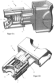
- Figure 1A shows the underside of an embodiment of the claimed device.
- Figure 1B shows the top of the device.
- the device (10, 10a, 10b) is used to attach a washing arm (20) in a dishwasher (40), the device (10, 10a, 10b) comprising the following: a first component (1) which has a locking lug (11) having, wherein the detent (11) is designed to engage on a part of the flushing arm (20); a second component (2) having a recess (21) through which the second component (2) is designed to rest on substantially half the circumference of an axis of rotation (4) for the flushing arm (20); a third component (3) which is elastic, the third component (3) being fixed to the first component (1) and to the second component (2) and in this way being positioned between the first component (1) and the second component ( 2) extends that the first component (1) and the second component (2) towards and away from each other (see arrow in Figure 1B ) are movably arranged, wherein the third component (3) is designed to move the first and second component (1, 2) away from each other and thereby the latching of the locking lug (11) on the part of the spray arm (20) and the resting of the
- the device (10, 10a, 10b) may have a recess (21) that is (substantially) semi-circular or (substantially) in the shape of half a rectangle or square.
- the second component (2) can be designed to rest on half the circumference of the axis of rotation (4).
- the recess (21) can be dimensioned and shaped in such a way that the second component (2) is thereby laid out on an arc of a circle which is a sector of a circle with an angle in the range from 160° to 180°, preferably 170° to 180°, in particular preferably 180° to rest along the circumference of the axis of rotation (4).
- the third component (3) is preferably a compression spring. Such a compression spring supplies the restoring force in order to move the first component and the second component away from one another.
- the third component (3) can be designed to move the first and second component (2) away from one another and thereby cause the second component (2) to rest on half the circumference of the axis of rotation (4).
- Fastening the rinsing arm (20) in the dishwasher (40) includes, for example, moving the first and second components (2) away from one another, thereby causing the latching lug (11) to engage on the part of the rinsing arm (20) and the second component (2) is effected on essentially half the circumference of the axis of rotation (4).
- the first component (1) can be a latch pusher and the second component (2) can be a latch catch.
- the first, second and third component (3) can be snapped together.
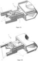
- Figure 2A shows the underside of an embodiment of the claimed device.
- Figure 2B shows the top of the device.
- the first component (1) can have one or more pins (12) which are designed to be moved past the axis of rotation by the movement of the first component (1) towards the second component (2) and thereby the attachment of the To solve the rinse arm (20) in the dishwasher (40).
- Each of the one or more pins (12) is assigned one or more bearing surfaces (13) of the second component (2) of a further device located opposite on the other side of the axis of rotation (4).
- the movement of the first and second component (1, 2) away from each other can be limited by the detent (11) and/or one or more additional detents (22), the second component (2) having the one or more additional detents (22 ) and the one or more further latching lugs (22) on the first component (1) can be latched in a detachable manner.
- the first and second component (2) can slide along one another, for example on guide surfaces (14), in order to promote easy and safe sliding of the individual parts towards one another.
- the first component (1) may have a handle (16) for a user to effect movement of the first component (1) towards the second component (2).
- the third component (3) can be designed, when the user releases the handle (16), to move the first and second components (2) away from one another and thereby engage the latching lug (11) on the part of the spray arm (20) and causing the second component (2) to rest on the circumference of the axis of rotation (4).
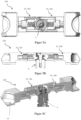
- Figure 3A shows the top of an embodiment of the claimed assembly (100) in a state in which the flushing arm is attached to the axis of rotation.
- Figures 3B and 3C Fig. 12 shows a side cross-section of the assembly in the state where the flushing arm is attached to the rotation axis.
- the assembly (100) includes: a first (10a) of any of the devices (10) described herein and a second (10b) of any of the devices (10) described herein (the first device 10a may be the same as or different from the second device 10b), the first and second devices (10a, 10b) are designed, by moving the part of the first component (1) of the first (10a) of the two devices (10a, 10b) past the axis of rotation, the second component (2) of the second device (10b), which is arranged opposite and adjacent to the second component (2) of the first device (10a), away from the axis of rotation (4) or the recess (21) of the second component (2) of the first device (10a), in order to thereby prevent the second Cancel component (2) of the second device (10b) on the circumference of the axis of rotation (4).
- Figure 4A shows the top of an embodiment of the claimed assembly in a state in which the flushing arm is not attached to the axis of rotation.
- Figure 4B Fig. 12 shows a side cross-section of the assembly in the state where the wash arm is not fixed to the rotation axis.
- the second component (2) of the first device (10a) and the second component (2) of the second device (10b) can each be designed due to their recesses (21) together to partially or completely enclose the circumference of the axis of rotation (4) and thereon to lay up
- the first device (10a) and the second device (10b) can lie in a common plane.
- the recess (21) of the second component (2) of the first device (10a) and the recess (21) of the second component (2) of the second device (10b) can lie in a common plane.
- the pins (12) located on the latch pusher can, when actuated, push back the opposite latch catch (e.g. component 2 of device 10b).
- the second component or the bolt catch (2) of the first and second device (10a, 10b) of the assembly (100) has surfaces on which the pins (12) of the opposite first component or bolt pusher (1) Press when pressing and push the second component or the latch catch (2) backwards, i.e. away from the axis of rotation, in order to expose the axis of rotation and thus release the attachment of the rinse arm in the dishwasher.
- the first component or latch pusher (1) of each device (10, 10a, 10b) described here can have a sliding surface (15) towards the rinsing arm or the area to be washed, which allows the individual parts to slide easily and safely in relation to the rinsing arm or Promote rinsing field and thus allow easier operation by the user (by means of handle 16).
- the handle (16) allows the user to actuate the first component or latch pusher (1) ergonomically.
- the devices (10, 10a, 10b) described here and the assembly described here make it possible for the fastening means (bolt) of the rinsing arm to be able to be mounted on the axis of rotation in the dishwasher as the last component. There are therefore no disruptive components during the welding of the individual shells of the spray arm.
- the plain bearing on the rotation axis is evenly loaded by the up to 360° enclosure.
- the device described here comprises three components, namely the first component (1), the so-called control handle, the second component (2), the so-called bolt catch, and a third, elastic component (3), which is preferably a compression spring is.
- a locking lug (11) on the latch handle which can snap into place on the counterpart, the flushing arm or flushing field, and thus holds the assembly (100) securely in the flushing arm or flushing field.
- the locking lug (11) enables the assembly (100) to snap in after the welding process of the two individual shells of the rinsing arm or rinsing field.
- the assembly (100) itself can also be held together by the two further latching lugs (22) on the bolt catch, which snap into place on the bolt handle.
- the compression spring presses the two components into their final position.
- One bar assembly (100) is snapped into the flushing field from the left and one from the right.
- the opposite bolt catch is pushed backwards via two pins (12) located on the bolt handle, i.e. pushed away from the axis of rotation (4). This releases the area around the axis of rotation (4) and the spray arm (20) can be installed or removed. After releasing, the first and second components are pressed back into their end position by the spring and the axis of rotation is enclosed.
- the detent (11) disengages from that part of the spray arm (20) where the detent was originally engaged before the user actuated the first component (1).
- the detent (11) ensures that the device (10, 10a) is securely fastened in the spray arm (20) during the rotation of the spray arm.
- one or more pins (12) of the first component (1) are pushed laterally past the axis of rotation (4) in order to, by means of contact of the pins with a or several associated bearing surfaces (13) of the opposite second component (2) of a further, second device (10b), to push the second component (2) away from the axis of rotation (4) and at the same time to push the third component (3) of the second device ( 10b) to press together or to build up potential energy therein.
- the axis of rotation is at least partially exposed and the Loosened the attachment of the rinse arm to the rotation axis in the dishwasher.
- the detent (11) of the first component of the second device (10b) also ensures that the second or third component of the second device during this process, and no simultaneous actuation of the first component of the second device by the user, a resistance such it is provided that the first component of the second device does not move away from the axis of rotation by this process.
- the first component (1) of the second device (10b) in which the user pushes the first component in the direction the axis of rotation and thus additionally compresses the third component of the second device or further builds up potential energy therein the one or more pins (12) of the second device are pushed laterally past the axis of rotation (4) in order to, by means of contact of the pins with or several associated bearing surfaces (13) of the second component (2) of the first device (10a), to push the second component (2) of the first device (10a) away from the axis of rotation and, if necessary, at the same time to push the third component of the first device (10a ) to press further together or to build up further potential energy in it.
- This removal of the second component of the first device (10a) in front of the axis of rotation further exposes the axis of rotation (4) and the process of releasing the attachment of the washing arm to the axis of rotation in the dishwasher continues.
- the attachment of the rinsing arm (20) to the axis of rotation (4) in the dishwasher is already released, whereby in any case when the two first components (1 ) of the first and second devices (10a, 10b), the axis of rotation is completely exposed, and the rinsing arm can be removed from the axis of rotation, for example to clean or replace the rinsing arm.
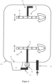
- Figure 12 shows a side cross-section of an embodiment of the claimed flushing system in the state where the flushing arm is attached to the axis of rotation.
- FIG 6 shows an embodiment of the claimed dishwasher.
- the dishwasher (40) includes the rinsing system (30).
- Each of the spray arms (20) can rotate slightly around the rotation axis (4) (see arrows in figures 5 and 6 ) and by operating one or both of the first components (1) of the assembly (100) slightly in the direction (see arrows in figures 5 and 6 ) of the axis of rotation (4) are pulled down from the axis of rotation (4).
Landscapes
- Washing And Drying Of Tableware (AREA)
Description
- Die vorliegende Erfindung betrifft eine Vorrichtung zur Befestigung eines Spülarms in einer Spülmaschine, und eine entsprechende Baugruppe, ein entsprechendes Spülsystem und eine entsprechende Spülmaschine jeweils mit Verwendung dieser Vorrichtung.
- In Spülmaschinen wird das Spülgut üblicherweise mit Spüllauge gereinigt und anschließend mit klarem Frischwasser nachgespült. Es wird je nach Bauart zwischen Transportgeschirrspülmaschinen (Korb- oder Bandtransportmaschinen), und Programmautomaten (Haubendurchschubmaschine mit Haube oder Untertischmaschine mit Tür) unterschieden.
- Geschirrspülmaschinen verfügen typischerweise über eine Behandlungszone, in der das Spülgut mit Wasser und Spülmittel beaufschlagt wird, sowie über eine Zone zum Beladen der Spülmaschine mit Spülgut, wobei diese Zone zum Beladen von Spülgut bei einer Transportgeschirrspülmaschine in der Regel ein Vorhang oder eine Tür umfasst, bei einer Haubendurchschubmaschine eine Haube umfasst und bei einer Untertischmaschine in der Regel eine Tür umfasst durch die jeweils das Spülgut in die Behandlungszone eingebracht wird.
- Für eine Beladung der Geschirrspülmaschine mit zu reinigendem Spülgut kommen in der Regel Spülgutbehälter, wie zum Beispiel Spülkörbe, zum Einsatz, die für den Verwender aus der Geschirrspülmaschine bzw. Behandlungszone herausnehmbar ausgebildet sind.
- Insbesondere aus Gründen des Umweltschutzes und des sparsamen Umgangs mit Ressourcen (insbesondere Wasser, Chemie und Energie) werden immer größere Anforderungen an solche Spülmaschinen gestellt.
- Zum Beaufschlagen von zu reinigendem Spülgut mit Spülflüssigkeit verfügt die Geschirrspülmaschine in der Behandlungszone über eine Sprüheinrichtung wie zum Beispiel einen Spülarm mit Sprühdüsen.
- In Geschirrspülmaschinen finden heute drehende Spülarme häufigen Einsatz. Diese Spülarme sollten zur täglichen Reinigung aus der Maschine herausgenommen werden, sodass eine schnelle Verriegelung oder Verrastung auf der Spülmaschine wünschenswert wäre. Dazu können Schnappriegel verwendet werden.
- Bei Spülsystemen sowohl im gewerblichen wie auch im häuslichen Bereich ist die Reduzierung der Nachspülmenge von großer Bedeutung. Da das Spülfeld bzw. der Spülarm über eine Wasserdüse angetrieben wird und dieses Wasser nicht mehr der Nachspülung zur Verfügung steht, wäre hier eine leichtgängige Lagerung des Spülfeldes wünschenswert, um die Nachspülmenge zu reduzieren. Häufig wird die Kraft jedoch nur über zwei Teilflächen, also nur mittels einer teilweisen Umschließung der Rotationsachse, übertragen, was zu erhöhten Reibkräften führen kann. Außerdem kann die Auflagefläche durch die tägliche Entnahme des Spülarms sowie durch unsachgemäße Anwendung aufgrund der nur teilweisen Schließung schnell verschleißen.
- Ferner muss oftmals vor dem Fügen der Oberschale und Unterschale des Spülarms die Verriegelung montiert werden, da die Riegel bauartbedingt nicht nachträglich in das Spülfeld eingeschnappt werden können. Da die Spülfeldschalen oftmals miteinander verschweißt werden, wären die Riegel beim Schweißprozess im Weg.
-
US 2013/206179 A1 offenbart einen Armmechanismus einer Geschirrspülmaschine, der eine Flüssigkeitsversorgungswellenanordnung mit einem darauf montierten drehbaren Gleitlager und eine Armanordnung mit einem länglichen inneren Flüssigkeitsströmungsraum entlang eines Armkörpers und einer oder mehreren Flüssigkeitsausstoßöffnungen umfasst. Die Armanordnung ist über einen Verriegelungsmechanismus der Armanordnung, der in das drehbare Gleitlager eingreift, lösbar an der Zufuhrwellenanordnung montiert, so dass sich die Armanordnung während des Ausstoßens von Flüssigkeit aus den Flüssigkeitsausstoßöffnungen mit dem drehbaren Gleitlager dreht. - Es ist daher eine Aufgabe der vorliegenden Erfindung eine Vorrichtung zur Befestigung eines Spülarms in einer Spülmaschine bereitzustellen, die für den Benutzer einfach zu bedienen ist, als letzten Arbeitsschritt in die Montage erfolgen kann und den Umfang der Rotationsachse des Spülarms zu einem größeren Anteil (bis hin zu vollständig) umschließt.
- Diese Aufgabe wird durch eine Baugruppe gemäß Anspruch 1, ein Spülsystem gemäß Anspruch 14 und eine Spülmaschine gemäß Anspruch 15 gelöst. Die Unteransprüche betreffen besonders vorteilhafte Ausführungsformen.
- Die Erfindung löst diese Aufgabe, weil die erfindungsgemäße Baugruppe die Merkmale von Anspruch 1 aufweist.
- Das erfindungsgemäße Spülsystem und die erfindungsgemäße Spülmaschine umfassen jeweils diese erfindungsgemäße Baugruppe.
- Durch die Rastnase kann der Spülarm während der Rotation des Spülarms verlässlich in Position gehalten werden. Durch das Aufliegen des zweiten Bauteils mit seiner Aussparung auf im Wesentlichen der Hälfte des Umfangs der Rotationsachse erlaubt die Umschließung der Rotationsachse zu einem größeren Anteil, nämlich zu einem im Wesentlichen vollständigen Umschließen der Achse unter Verwendung der Baugruppe.
- Die größere Auflagefläche verringert den Verschleiß im Gegensatz zu einer geringeren, teilweisen Schließung der Achse. Durch die vergrößerte Auflagefläche wird auch die Kraft gleichmäßig auf die Rotationsachse übertragen, was dazu führt, dass sich der Spülarm leichter dreht, was wiederum zu einer Reduzierung der benötigten Wasser-Nachspülmenge führt. Ferner kann die Vorrichtung als letztes Teil in der Montage, also nach dem Schweißvorgang der beiden Spülfeldschalen des Spülarms, verbaut werden, bei Defekt ausgetauscht werden und händisch betrieben werden. Dies führt zu einer deutlich verbesserten Fertigung, zu einer deutlich verbesserten Wartung und zu einem einfacheren Betrieb durch den Benutzer.
- Diese und weitere Merkmale und Vorteile der Erfindung werden anhand der nachfolgenden detaillierten Beschreibung von weiteren bevorzugten Ausführungsformen besonders deutlich.
-
- Fig. 1A
- zeigt die Unterseite einer Ausführungsform der beanspruchten Vorrichtung.
- Fig. 1B
- zeigt die Oberseite einer Ausführungsform der beanspruchten Vorrichtung.
- Fig. 2A
- zeigt die Unterseite einer Ausführungsform der beanspruchten Vorrichtung.
- Fig. 2B
- zeigt die Oberseite einer Ausführungsform der beanspruchten Vorrichtung.
- Fig. 3A
- zeigt die Oberseite einer Ausführungsform der beanspruchten Baugruppe in einem Zustand in dem der Spülarm an der Rotationsachse befestigt ist.
- Fig. 3B
- zeigt einen seitlichen Querschnitt einer Ausführungsform der beanspruchten Baugruppe in dem Zustand in dem der Spülarm an der Rotationsachse befestigt ist.
- Fig. 3C
- zeigt einen seitlichen Querschnitt einer Ausführungsform der beanspruchten Baugruppe in dem Zustand in dem der Spülarm an der Rotationsachse befestigt ist.
- Fig. 4A
- zeigt die Oberseite einer Ausführungsform der beanspruchten Baugruppe in einem Zustand in dem der Spülarm nicht an der Rotationsachse befestigt ist.
- Fig. 4B
- zeigt einen seitlichen Querschnitt einer Ausführungsform der beanspruchten Baugruppe in dem Zustand in dem der Spülarm nicht an der Rotationsachse befestigt ist.
- Fig. 5
- zeigt einen seitlichen Querschnitt einer Ausführungsform das beanspruchten Spülsystems in dem Zustand in dem der Spülarm an der Rotationsachse befestigt ist.
- Fig. 6
- zeigt eine Ausführungsform der beanspruchten Spülmaschine.
-
Figur 1A zeigt die Unterseite einer Ausführungsform der beanspruchten Vorrichtung.Figur 1B zeigt die Oberseite der Vorrichtung. - Die Vorrichtung (10, 10a, 10b) dient der Befestigung eines Spülarms (20) in einer Spülmaschine (40), wobei die Vorrichtung (10, 10a, 10b) Folgendes umfasst: ein erstes Bauteil (1), das eine Rastnase (11) aufweist, wobei die Rastnase (11) ausgelegt ist, an einem Teil des Spülarms (20) einzurasten; ein zweites Bauteil (2), das eine Aussparung (21) aufweist durch die das zweite Bauteil (2) ausgelegt ist, auf im Wesentlichen der Hälfte des Umfangs einer Rotationsachse (4) für den Spülarm (20) aufzuliegen; ein drittes Bauteil (3), das elastisch ist, wobei das dritte Bauteil (3) an dem ersten Bauteil (1) und an dem zweiten Bauteil (2) befestigt ist und sich derart zwischen dem ersten Bauteil (1) und dem zweiten Bauteil (2) erstreckt, dass das erste Bauteil (1) und das zweite Bauteil (2) aufeinander zu und voneinander weg (siehe Pfeil in
Fig. 1B ) bewegbar angeordnet sind, wobei das dritte Bauteil (3) ausgelegt ist, das erste und zweite Bauteil (1, 2) voneinander weg zu bewegen und dadurch das Einrasten der Rastnase (11) an dem Teil des Spülarms (20) und das Aufliegen des zweiten Bauteils (2) auf im Wesentlichen der Hälfte des Umfangs der Rotationsachse (4) zu bewirken, und wobei die Vorrichtung (10, 10a, 10b) ausgelegt ist, durch eine Bewegung des ersten Bauteils (1) auf das zweite Bauteil (2) zu, die Rastnase (11) von dem Teil des Spülarms (20) zu lösen und ein Teil des ersten Bauteils (1) an der Rotationsachse (4) vorbei zu bewegen. - Die Vorrichtung (10, 10a, 10b) kann eine Aussparung (21) haben, die (im Wesentlichen) halbkreisförmig ist oder (im Wesentlichen) die Form einer Hälfte eines Rechtecks oder Quadrats aufweist.
- Das zweite Bauteil (2) kann ausgelegt sein, auf der Hälfte des Umfangs der Rotationsachse (4) aufzuliegen.
- Die Aussparung (21) kann derart dimensioniert und geformt sein, dass dadurch das zweite Bauteil (2) ausgelegt ist, auf einem Kreisbogen, der einem Kreisausschnitt mit einem Winkel im Bereich von 160° bis 180°, vorzugsweise 170° bis 180°, besonders bevorzugt 180°, entlang des Umfangs der Rotationsachse (4) aufzuliegen.
- Vorzugsweise ist das dritte Bauteil (3) eine Druckfeder. Eine solche Druckfeder liefert die Rückstellkraft um das erste Bauteil und das zweite Bauteil voneinander zu entfernen.
- Das dritte Bauteil (3) kann ausgelegt sein, das erste und zweite Bauteil (2) voneinander weg zu bewegen und dadurch das Aufliegen des zweiten Bauteils (2) auf der Hälfte des Umfangs der Rotationsachse (4) zu bewirken.
- Die Befestigung des Spülarms (20) in der Spülmaschine (40) umfasst beispielsweise, dass das erste und zweite Bauteil (2) voneinander weg bewegt werden und dadurch das Einrasten der Rastnase (11) an dem Teil des Spülarms (20) und das Aufliegen des zweiten Bauteils (2) auf im Wesentlichen der Hälfte des Umfangs der Rotationsachse (4) bewirkt wird.
- Das erste Bauteil (1) kann ein Riegel-Drücker sein und das zweite Bauteil (2) kann ein Riegel-Schnapper sein. Das erste, zweite und dritte Bauteil (3) können miteinander verschnappbar sein.
-
Figur 2A zeigt die Unterseite einer Ausführungsform der beanspruchten Vorrichtung.Fig. 2B zeigt die Oberseite der Vorrichtung. - Das erste Bauteil (1) kann ein oder mehrere Stifte (12) aufweisen, die ausgelegt sind, durch die Bewegung des ersten Bauteils (1) auf das zweite Bauteil (2) zu, an der Rotationsachse vorbei bewegt zu werden und dadurch die Befestigung des Spülarms (20) in der Spülmaschine (40) zu lösen. Jeder der ein oder mehreren Stifte (12) sind dabei ein oder mehreren Auflageflächen (13) des zweiten Bauteils (2) einer weiteren, auf der anderen Seite der Rotationsachse (4) gegenüberliegenden Vorrichtung zugeordnet.
- Die Bewegung des ersten und zweiten Bauteils (1, 2) voneinander weg kann durch die Rastnase (11) und/oder ein oder mehrere weitere Rastnasen (22) begrenzt werden, wobei das zweite Bauteil (2) die ein oder mehreren weiteren Rastnasen (22) aufweist und die eine oder mehreren weiteren Rastnasen (22) am ersten Bauteil (1) lösbar einrastbar sind.
- Das erste und zweite Bauteil (2) können bei den Bewegungen aufeinander zu und voneinander weg aneinander, beispielsweise an Führungsflächen (14), entlang gleiten, um ein leichtes und sicheres gleiten der Einzelteile zueinander zu fördern.
- Das erste Bauteil (1) kann einen Griff (16) für einen Benutzer aufweisen, nämlich zur Bewirkung der Bewegung des ersten Bauteils (1) auf das zweite Bauteil (2) zu.
- Das dritte Bauteil (3) kann ausgelegt sein, bei Loslassen des Griffs (16) durch den Benutzer, das erste und zweite Bauteil (2) voneinander weg zubewegen und dadurch das Einrasten der Rastnase (11) an dem Teil des Spülarms (20) und das Aufliegen des zweiten Bauteils (2) auf dem Umfang der Rotationsachse (4) zu bewirken.
-
Figur 3A zeigt die Oberseite einer Ausführungsform der beanspruchten Baugruppe (100) in einem Zustand in dem der Spülarm an der Rotationsachse befestigt ist.Figuren 3B und 3C zeigt einen seitlichen Querschnitt der Baugruppe in dem Zustand in dem der Spülarm an der Rotationsachse befestigt ist. - Die Baugruppe (100) umfasst:
eine erste (10a) irgendeiner der hier beschriebenen Vorrichtungen (10) und eine zweite (10b) irgendeiner der hier beschriebenen Vorrichtungen (10) (die erste Vorrichtung 10a kann identisch oder verschieden sein von der zweiten Vorrichtung 10b), wobei die erste und zweite Vorrichtungen (10a, 10b) ausgelegt sind, durch die Bewegung des Teils des ersten Bauteils (1) der ersten (10a) der zwei Vorrichtungen (10a, 10b) an der Rotationsachse vorbei das zweite Bauteil (2) der zweiten Vorrichtung (10b), welches dem zweiten Bauteil (2) der ersten Vorrichtung (10a) gegenüber und angrenzend angeordnet ist, von der Rotationsachse (4) oder der Aussparung (21) des zweiten Bauteils (2) der ersten Vorrichtung (10a) wegzuschieben, um dadurch das Aufliegen des zweiten Bauteils (2) der zweiten Vorrichtung (10b) auf dem Umfang der Rotationsachse (4) aufzuheben. -
Figur 4A zeigt die Oberseite einer Ausführungsform der beanspruchten Baugruppe in einem Zustand in dem der Spülarm nicht an der Rotationsachse befestigt ist.Fig. 4B zeigt einen seitlichen Querschnitt der Baugruppe in dem Zustand in dem der Spülarm nicht an der Rotationsachse befestigt ist. - Das zweite Bauteil (2) der ersten Vorrichtung (10a) und das zweite Bauteil (2) der zweiten Vorrichtung (10b) kann jeweils ausgelegt sein aufgrund ihrer Aussparungen (21) zusammen den Umfang der Rotationsachse (4) teilweise oder vollständig zu umschließen und darauf aufzuliegen.
- Die erste Vorrichtung (10a) und die zweite Vorrichtung (10b) können in einer gemeinsamen Ebene liegen. Die Aussparung (21) des zweiten Bauteils (2) der ersten Vorrichtung (10a) und die Aussparung (21) des zweiten Bauteils (2) der zweiten Vorrichtung (10b) können in einer gemeinsamen Ebene liegen.
- In der Baugruppe (100) können die am Riegel-Drücker (z.B. Bauteil 1 von Vorrichtung 10a) befindlichen Stifte (12), bei Betätigung, den gegenüberliegenden Riegel-Schnapper (z.B. Bauteil 2 von Vorrichtung 10b) zurückschieben. Das zweite Bauteil bzw. der Riegel-Schnapper (2) von der ersten und zweiten Vorrichtung (10a, 10b) der Baugruppe (100) weist dabei jeweils Flächen auf, auf die die Stifte (12) des gegenüberliegenden ersten Bauteils bzw. Riegel-Drückers (1) beim Betätigen drücken und das zweite Bauteil bzw. den Riegel-Schnapper (2) so nach hinten, also von der Rotationsachse weg, schieben, um so die Rotationsachse freizulegen und somit die Befestigung des Spülarms in der Spülmaschine aufzuheben.
- Das erste Bauteil bzw. Riegel-Drücker (1) einer jeden hier beschriebenen Vorrichtung (10, 10a, 10b) kann Gleitfläche (15) hin zum Spülarm bzw. Spülgut Feld aufweisen, die ein leichtes und sicheres gleiten der Einzelteile gegenüber dem Spülarm bzw. Spülfeld fördern und somit ein leichteres Betätigen durch den Benutzer (mittels Griff 16) erlauben. Der Griff (16) erlaubt dem Benutzer das erste Bauteil bzw. Riegel-Drücker (1) ergonomisch betätigen zu können.
- Die hier beschriebenen Vorrichtungen (10 10a, 10b) und hier beschriebenen Baugruppe ermöglichen es, dass das Befestigungsmittel (Riegel) des Spülarms an der Rotationsachse in der Spülmaschine als letztes Bauteil montiert werden kann. Während des verschweißens der Einzelschalen des Spülarms gibt es somit kein störendes Bauteil. Das Gleitlager auf der Rotationsachse wird durch die bis zu 360° Umschließung gleichmäßig belastet.
- Die hierin beschriebene Vorrichtung umfasst dabei drei Bauteile, nämlich das erste Bauteil (1), der sogenannte Regel-Drücker, dem zweiten Bauteil (2), dem sogenannten Riegel-Schnapper, sowie ein drittes, elastisches Bauteil (3), welches vorzugsweise eine Druckfeder ist. Am Riegel-Drücker befindet sich eine Rastnase (11) welche am Gegenstück, dem Spülarm bzw. Spülfeld, einrasten kann und die Baugruppe (100) somit sicher im Spülarm bzw. Spülfeld hält. Die Rastnase (11) ermöglicht es, dass die Baugruppe (100) nach dem Schweißvorgang der beiden Einzelschalen des Spülarms bzw. Spülfeldes einzurasten.
- Die Baugruppe (100) selbst kann zusätzlich über die zwei weiteren Rastnasen (22) am Riegel-Schnapper, welche am Riegel-Drücker einrasten, zusammengehalten werden. Die Druckfeder drückt die beiden Bauteile in ihre Endposition. Es wird jeweils eine Riegel-Baugruppe (100) von links und eine von rechts in das Spülfeld eingerastet. Beim Betätigen der Riegel-Drücker wird der jeweils gegenüberliegende Riegel-Schnapper über zwei Stifte (12) die sich am Riegel-Drücker befinden, nach hinten geschoben, also von der Rotationsachse (4) weggeschoben. Dadurch wird der Bereich um die Rotationsachse (4) freigegeben und der Spülarm (20) kann ein bzw. ausgebaut werden. Nach dem Loslassen werden die ersten und zweiten Bauteile durch die Feder wieder in ihre Endposition gedrückt und die Rotationsachse wird umschlossen.
- Mit anderen Worten, wenn der Benutzer das erste Bauteil (1) einer ersten Vorrichtung (10, 10a), zum Beispiel mittels des Griffes (16), betätigt, also von außen Kraft auf das erste Bauteil (1) ausübt, sodass das dritte Bauteil (3) zusammengestaucht wird bzw. sich darin potentielle Energie aufbaut, löst sich die Rastnase (11) von dem Teil des Spülarms (20), wo die Rastnase ursprünglich eingerastet war, bevor der Benutzer das erste Bauteil (1) betätigte. Die Rastnase (11) sorgt dabei dafür, dass die Vorrichtung (10, 10a) sicher im Spülarm (20) während der Rotation des Spülarms befestigt ist. Während nun also das dritte Bauteil (3) zusammengedrückt wird bzw. sich darin potentielle Energie aufbaut, werden ein oder mehrere Stifte (12) des ersten Bauteils (1) seitlich an der Rotationsachse (4) vorbeigeschoben, um, mittels Kontakt der Stifte mit ein oder mehreren dazugehörigen Auflageflächen (13) des gegenüberliegenden zweiten Bauteils (2) einer weiteren, zweiten Vorrichtung (10b), das zweite Bauteil (2) von der Rotationsachse (4) weg zu schieben und gleichzeitig das dritte Bauteil (3) der zweiten Vorrichtung (10b) zusammen zu pressen bzw. darin potentielle Energie aufzubauen. Durch dieses Entfernen des zweiten Bauteils der zweiten Vorrichtung von der Rotationsachse weg wird die Rotationsachse zumindest teilweise freigelegt und die Befestigung des Spülarms an der Rotationsachse in der Spülmaschine gelöst. Die Rastnase (11) des ersten Bauteils der zweiten Vorrichtung (10b) sorgt dabei auch dafür, dass dem zweiten bzw. dritten Bauteil der zweiten Vorrichtung bei diesem Vorgang, und keiner gleichzeitigen Betätigung des ersten Bauteils der zweiten Vorrichtung durch den Benutzer, ein Widerstand derart bereitgestellt wird, dass sich das erste Bauteil der zweiten Vorrichtung durch diesen Vorgang nicht von der Rotationsachse weg bewegt.
- Betätigt, gleichzeitig oder zeitversetzt zur Betätigung des ersten Bauteils der ersten Vorrichtung, nun der Benutzer, zum Beispiel mittels Eingreifen in den Griff (16), das erste Bauteil (1) der zweiten Vorrichtung (10b) in dem der Benutzer das erste Bauteil in Richtung der Rotationsachse schiebt und somit das dritte Bauteil der zweiten Vorrichtung zusätzlich zusammenpresst bzw. darin potentielle Energie weiter aufbaut, werden die ein oder mehreren Stifte (12) der zweiten Vorrichtung seitlich an der Rotationsachse (4) vorbeigeschoben, um, mittels Kontakt der Stifte mit ein oder mehreren dazugehörigen Auflageflächen (13) des zweiten Bauteils (2) der ersten Vorrichtung (10a), das zweite Bauteil (2) der ersten Vorrichtung (10a) von der Rotationsachse weg zu schieben und ggf. gleichzeitig das dritte Bauteil der ersten Vorrichtung (10a) weiter zusammen zu pressen bzw. weitere potentielle Energie darin aufzubauen. Durch diese Entfernung des zweiten Bauteils der ersten Vorrichtung (10a) vor der Rotationsachse weg wird die Rotationsachse (4) weiter freigelegt und der Vorgang des Auflösens der Befestigung des Spülarms an der Rotationsachse in der Spülmaschine weiter fortgeführt. Durch Betätigung eines der ersten Bauteile (1) der zwei Vorrichtungen (10a, 10b) wird die Befestigung des Spülarms (20) an der Rotationsachse (4) in der Spülmaschine schon aufgehoben, wobei in jedem Falle bei der Betätigung von beiden ersten Bauteilen (1) der ersten und zweiten Vorrichtungen (10a, 10b) die Rotationsachse komplett freigelegt wird, und der Spülarm kann von der Rotationsachse entfernt werden, zum Beispiel um den Spülarm zu reinigen oder auszutauschen.
-
Figur 5 zeigt einen seitlichen Querschnitt einer Ausführungsform des beanspruchten Spülsystems in dem Zustand in dem der Spülarm an der Rotationsachse befestigt ist. - Das Spülsystem (30) für eine Spülmaschine (40) umfasst dabei:
- eine der hierin beschriebenen Baugruppen (100);
- den Spülarm (20);
- die Rotationsachse (4) zur Rotation des Spülarms (20);
- wobei die Rotationsachse (4) derart durch die Baugruppe (100) verläuft, dass, in jeder der ersten Vorrichtung (10a) und der zweiten Vorrichtung (10b) der Baugruppe (100), das dritte Bauteil (3) sich senkrecht zur Rotationsachse (4) zwischen dem ersten Bauteil (1) und dem zweiten Bauteil (2) erstreckt, so dass das erste Bauteil (1) und das zweite Bauteil (2) senkrecht zur Rotationsachse (4) aufeinander zu und voneinander weg bewegbar angeordnet sind, und die Rotationsachse (4) sowohl durch die Aussparung (21) der ersten Vorrichtung (10a) als auch durch die Aussparung (21) der zweiten Vorrichtung (10b) verläuft.
-
Figur 6 zeigt eine Ausführungsform der beanspruchten Spülmaschine. Die Spülmaschine (40) umfasst dabei das Spülsystem (30). Eine Zuleitung (41) für die Zuleitung von Leitungswasser, ein oder mehrere Umwälzpumpen (42), einen Tank (43) mit einem Sieb (44), ein oder mehrere Leitungen (45) von dem Tank (43) zu den ein oder mehreren Spülarmen (20), wobei die Leitungen (45) und die Pumpe (42) Spülflüssigkeit von dem Tank (43) zu den Sprühdüsen (46) der Spülarme (20) leitet. Jeder der Spülarme (20) kann dabei leicht um die Rotationsachse (4) rotieren (siehe Pfeile inFiguren 5 und6 ) und mittels Betätigung eines oder beider ersten Bauteile (1) der Baugruppe (100) leicht in Richtung (siehe Pfeile inFiguren 5 und6 ) der Rotationsachse (4) von der Rotationsachse (4) heruntergezogen werden. - Diese und weitere in der vorstehenden Beschreibung, den Ansprüchen und der Zeichnung offenbarten (optionalen) Merkmale können sowohl einzeln als auch in beliebiger Kombination für die Ausführung der Erfindung in ihren verschiedenen Ausgestaltungen Verwendung finden.
Referenzzeichenliste: erstes Bauteil 1 zweites Bauteil 2 drittes Bauteil 3 Rotationsachse 4 Vorrichtung 10, 10a, 10b Rastnase 11 Stifte 12 Auflagefläche 13 Führungsfläche 14 Gleitfläche 15 Griff 16 Spülarm 20 Aussparung 21 weitere Rastnasen 22 Spülsystem 30 Spülmaschine 40 Zuleitung 41 Pumpe 42 Tank 43 Sieb 44 Leitungen 45 Baugruppe 100
Claims (15)
- Eine Baugruppe (100), umfassend:eine erste Vorrichtung (10, 10a) zur Befestigung eines Spülarms (20) in einer Spülmaschine (40) und eine zweite Vorrichtung (10, 10b) zur Befestigung des Spülarms (20) in der Spülmaschine (40), die erste Vorrichtung (10, 10a) und die zweite Vorrichtung (10, 10b) jeweils umfassend:ein erstes Bauteil (1);ein zweites Bauteil (2), das eine Aussparung (21) aufweist durch die das zweite Bauteil (2) ausgelegt ist, auf im Wesentlichen der Hälfte des Umfangs einer Rotationsachse (4) für den Spülarm (20) aufzuliegen; undein drittes Bauteil (3), das elastisch ist;wobei das zweite Bauteil (2) der ersten Vorrichtung (10a) und das zweite Bauteil (2) der zweiten Vorrichtung (10b) ausgelegt sind aufgrund ihrer Aussparungen (21) zusammen den Umfang der Rotationsachse (4) im Wesentlichen vollständig zu umschließen;die erste Vorrichtung (10, 10a) und die zweite Vorrichtung (10, 10b) ist jeweils dadurch gekennzeichnet, dassdas erste Bauteil (1) eine Rastnase (11) aufweist, wobei die Rastnase (11) ausgelegt ist, an einem Teil des Spülarms (20) einzurasten, unddadurch, dass das dritte Bauteil (3) an dem ersten Bauteil (1) und an dem zweiten Bauteil (2) befestigt ist und sich derart zwischen dem ersten Bauteil (1) und dem zweiten Bauteil (2) erstreckt, dass das erste Bauteil (1) und das zweite Bauteil (2) aufeinander zu und voneinander weg bewegbar angeordnet sind, unddadurch, dass das dritte Bauteil (3) ausgelegt ist, das erste und zweite Bauteil (1, 2) voneinander weg zu bewegen und dadurch das Einrasten der Rastnase (11) an dem Teil des Spülarms (20) und das Aufliegen des zweiten Bauteils (2) auf im Wesentlichen der Hälfte des Umfangs der Rotationsachse (4) zu bewirken, unddadurch, dass die Vorrichtung (10, 10a, 10b) ausgelegt ist, durch eine Bewegung des ersten Bauteils (1) auf das zweite Bauteil (2) zu, die Rastnase (11) von dem Teil des Spülarms (20) zu lösen und ein Teil des ersten Bauteils (1) an der Rotationsachse vorbei zu bewegen.
- Die Baugruppe (100) nach Anspruch 1, wobei die Aussparung (21) halbkreisförmig oder im wesentlichen halbkreisförmig ist.
- Die Baugruppe (100) nach einem der vorangehenden Ansprüche, wobei das zweite Bauteil (2) ausgelegt ist, auf der Hälfte des Umfangs der Rotationsachse (4) aufzuliegen.
- Die Baugruppe (100) nach einem der vorangehenden Ansprüche, wobei die Aussparung (21) derart dimensioniert und geformt ist, dass dadurch das zweite Bauteil (2) ausgelegt ist, auf einem Kreisbogen, der einem Kreisausschnitt mit einem Winkel im Bereich von 160° bis 180°, vorzugsweise 170° bis 180°, besonders bevorzugt 180°, entlang des Umfangs der Rotationsachse (4) aufzuliegen.
- Die Baugruppe (100) nach einem der vorangehenden Ansprüche, wobei das dritte Bauteil (3) eine Druckfeder ist.
- Die Baugruppe (100) nach einem der vorangehenden Ansprüche, wobei das dritte Bauteil (3) ausgelegt ist, das erste und zweite Bauteil (2) voneinander weg zu bewegen und dadurch das Aufliegen des zweiten Bauteils (2) auf der Hälfte des Umfangs der Rotationsachse (4) zu bewirken.
- Die Baugruppe (100) nach einem der vorangehenden Ansprüche, wobei die Befestigung des Spülarms (20) in der Spülmaschine (40) umfasst, dass das erste und zweite Bauteil (2) voneinander weg bewegt werden und dadurch das Einrasten der Rastnase (11) an dem Teil des Spülarms (20) und das Aufliegen des zweiten Bauteils (2) auf im Wesentlichen der Hälfte des Umfangs der Rotationsachse (4) bewirkt wird.
- Die Baugruppe (100) nach einem der vorangehenden Ansprüche, wobei das Teil des ersten Bauteils (1), welches Teil an der Rotationsachse vorbei bewegbar ist, ein oder mehrere Stifte (12) aufweist, die ausgelegt sind, durch ihre Bewegung an der Rotationsachse vorbei, die Befestigung des Spülarms (20) in der Spülmaschine (40) zu lösen.
- Die Baugruppe (100) nach einem der vorangehenden Ansprüche, wobei die Bewegung des ersten und zweiten Bauteils (2) voneinander weg durch die Rastnase (11) und/oder ein oder mehrere weitere Rastnasen (22) begrenzt wird, wobei das zweite Bauteil (2) die ein oder mehreren weiteren Rastnasen (22) aufweist und die eine oder mehreren weiteren Rastnasen (22) am ersten Bauteil (1) lösbar einrastbar sind.
- Die Baugruppe (100) nach einem der vorangehenden Ansprüche, wobei das erste und zweite Bauteil (2) bei den Bewegungen aufeinander zu und voneinander weg aneinander entlang gleiten.
- Die Baugruppe (100) nach einem der vorangehenden Ansprüche, wobei das erste Bauteil (1) einen Griff (16) für einen Benutzer aufweist zur Bewirkung der Bewegung des ersten Bauteils (1) auf das zweite Bauteil (2) zu, vorzugsweise wobei das dritte Bauteil (3) ausgelegt ist, bei Loslassen des Griffs (16) durch den Benutzer, das erste und zweite Bauteil (2) voneinander weg zubewegen und dadurch das Einrasten der Rastnase (11) an dem Teil des Spülarms (20) und das Aufliegen des zweiten Bauteils (2) auf dem Umfang der Rotationsachse (4) zu bewirken.
- Die Baugruppe (100) nach einem der vorangehenden Ansprüche,
wobei die erste und zweite Vorrichtungen (10a, 10b) ausgelegt sind, durch die Bewegung des Teils des ersten Bauteils (1) der ersten (10a) der zwei Vorrichtungen (10a, 10b) an der Rotationsachse vorbei das zweite Bauteil (2) der zweiten Vorrichtung (10b), welches dem zweiten Bauteil (2) der ersten Vorrichtung (10a) gegenüber und angrenzend angeordnet ist, von der Rotationsachse (4) oder der Aussparung (21) des zweiten Bauteils (2) der ersten Vorrichtung (10a) wegzuschieben, um dadurch das Aufliegen des zweiten Bauteils (2) der zweiten Vorrichtung (10b) auf dem Umfang der Rotationsachse (4) aufzuheben. - Die Baugruppe (100) nach einem der vorangehenden Ansprüche, wobei die erste Vorrichtung (10a) und die zweite Vorrichtung (10b) in einer gemeinsamen Ebene liegen, und/oder
wobei die Aussparung (21) des zweiten Bauteils (2) der ersten Vorrichtung (10a) und die Aussparung (21) des zweiten Bauteils (2) der zweiten Vorrichtung (10b) in einer gemeinsamen Ebene liegen. - Ein Spülsystem (30) für eine Spülmaschine (40), das Spülsystem (30) umfassend:die Baugruppe (100) nach einem der Ansprüche 1 bis 13;der Spülarm (20);die Rotationsachse (4) zur Rotation des Spülarms (20);wobei die Rotationsachse (4) derart durch die Baugruppe (100) verläuft, dass, in jeder der ersten Vorrichtung (10a) und der zweiten Vorrichtung (10b) der Baugruppe (100), das dritte Bauteil (3) sich senkrecht zur Rotationsachse (4) zwischen dem ersten Bauteil (1) und dem zweiten Bauteil (2) erstreckt, so dass das erste Bauteil (1) und das zweite Bauteil (2) senkrecht zur Rotationsachse (4) aufeinander zu und voneinander weg bewegbar angeordnet sind, und die Rotationsachse (4) sowohl durch die Aussparung (21) der ersten Vorrichtung (10a) als auch durch die Aussparung (21) der zweiten Vorrichtung (10b) verläuft.
- Eine Spülmaschine (40) umfassend das Spülsystem (30) nach Anspruch 14.
Applications Claiming Priority (2)
| Application Number | Priority Date | Filing Date | Title |
|---|---|---|---|
| DE102019121174.3A DE102019121174B4 (de) | 2019-08-06 | 2019-08-06 | Vorrichtung zur Befestigung eines Spülarms in einer Spülmaschine |
| PCT/EP2020/071543 WO2021023622A1 (de) | 2019-08-06 | 2020-07-30 | Vorrichtung zur befestigung eines spülarms in einer spülmaschine |
Publications (2)
| Publication Number | Publication Date |
|---|---|
| EP4009848A1 EP4009848A1 (de) | 2022-06-15 |
| EP4009848B1 true EP4009848B1 (de) | 2023-05-17 |
Family
ID=71899753
Family Applications (1)
| Application Number | Title | Priority Date | Filing Date |
|---|---|---|---|
| EP20750241.0A Active EP4009848B1 (de) | 2019-08-06 | 2020-07-30 | Vorrichtung zur befestigung eines spülarms in einer spülmaschine |
Country Status (4)
| Country | Link |
|---|---|
| EP (1) | EP4009848B1 (de) |
| DE (1) | DE102019121174B4 (de) |
| ES (1) | ES2950859T3 (de) |
| WO (1) | WO2021023622A1 (de) |
Family Cites Families (4)
| Publication number | Priority date | Publication date | Assignee | Title |
|---|---|---|---|---|
| US4869428A (en) * | 1988-08-08 | 1989-09-26 | Jackson Products Company | Hand actuated connect/disconnect spray arm arrangement for a dishwasher |
| US9763554B2 (en) * | 2012-02-14 | 2017-09-19 | Premark Feg L.L.G. | Warewash machine with removable rotating arm and related method |
| DE202014105113U1 (de) * | 2014-10-27 | 2014-11-03 | Illinois Tool Works Inc. | Spülarmsystem für Spülmaschine |
| EP3241479B1 (de) * | 2016-05-02 | 2018-07-11 | Bonferraro S.p.A. | Anordnung zum verbinden und trennen drehbare sprühärme von spülmaschinen |
-
2019
- 2019-08-06 DE DE102019121174.3A patent/DE102019121174B4/de active Active
-
2020
- 2020-07-30 ES ES20750241T patent/ES2950859T3/es active Active
- 2020-07-30 WO PCT/EP2020/071543 patent/WO2021023622A1/de not_active Ceased
- 2020-07-30 EP EP20750241.0A patent/EP4009848B1/de active Active
Also Published As
| Publication number | Publication date |
|---|---|
| DE102019121174A1 (de) | 2021-02-11 |
| WO2021023622A1 (de) | 2021-02-11 |
| ES2950859T3 (es) | 2023-10-16 |
| EP4009848A1 (de) | 2022-06-15 |
| DE102019121174B4 (de) | 2022-08-04 |
Similar Documents
| Publication | Publication Date | Title |
|---|---|---|
| EP3730027A1 (de) | Wasserführendes haushaltsgerät und verfahren zu seinem betrieb | |
| DE202014105113U1 (de) | Spülarmsystem für Spülmaschine | |
| DE3324381C2 (de) | Verriegelungsvorrichtung für eine Geschirrspülmaschine | |
| DE102007021255A1 (de) | Spanneinrichtung für Transporteinrichtung | |
| DE69903971T2 (de) | Verfahren und gerät zum prozess-waschen | |
| DE102019121174B4 (de) | Vorrichtung zur Befestigung eines Spülarms in einer Spülmaschine | |
| EP3727084B1 (de) | Reinigungsverfahren für pinsel | |
| DE2556520A1 (de) | Verriegelungsvorrichtung an der tuer einer geschirrspuelmaschine | |
| WO2005060813A1 (de) | Geschirrspüler mit festehenden sprühdüsen | |
| DE69827378T2 (de) | Vorrichtung zum Filtern von Waschflüssigkeit in einem Geschirrspüler | |
| DE7148062U (de) | Abstreifvorrichtung fuer fleischenthaeutungs- oder -entschwartungsmaschinen | |
| EP3586788A1 (de) | Kopplungsvorrichtung zum mechanischen und hydraulischen koppeln eines spülguts mit einem reinigungsgerät, spülgutträger und reinigungsgerät mit einer kopplungsvorrichtung | |
| DE19959627C2 (de) | Handbetätigte Presse mit Not-Entriegelungsknopf | |
| EP0457943A1 (de) | Wischgerät | |
| DE102011051737B4 (de) | Verfahren und Vorrichtung zum partiellen Abtragen einer Beschichtung | |
| EP2201886A1 (de) | Spülgutträger mit einem Anschlussstück für schlauchförmiges Reinigungsgut | |
| EP3991627A1 (de) | Vorrichtung zum übertragen eines drehmoments mit einer antreibbaren welle für eine geschirrspülmaschine sowie spülarm für eine geschirrspülmaschine | |
| DE29519774U1 (de) | Auswechselbare Textilbespannung für ein Reinigungsgerät | |
| DE202009002666U1 (de) | Vorrichtung zur Reinigung und/oder Aktivierung von Lötdüsen | |
| DE29604731U1 (de) | Einrichtung zur Aktivierung und Entaktivierung der Schalt- und Auswerferfunktion an elektrischen Haushaltsgeräten | |
| DE102014110397A1 (de) | Spülarmanordnung für eine programmgesteuerte Spülmaschine | |
| DE102005019624A1 (de) | Reinigungsgerät | |
| DE102023125277A1 (de) | Geschirrspülmaschine | |
| DE9416709U1 (de) | Haushaltsgerät | |
| DE1066949B (de) |
Legal Events
| Date | Code | Title | Description |
|---|---|---|---|
| STAA | Information on the status of an ep patent application or granted ep patent |
Free format text: STATUS: UNKNOWN |
|
| STAA | Information on the status of an ep patent application or granted ep patent |
Free format text: STATUS: THE INTERNATIONAL PUBLICATION HAS BEEN MADE |
|
| PUAI | Public reference made under article 153(3) epc to a published international application that has entered the european phase |
Free format text: ORIGINAL CODE: 0009012 |
|
| STAA | Information on the status of an ep patent application or granted ep patent |
Free format text: STATUS: REQUEST FOR EXAMINATION WAS MADE |
|
| 17P | Request for examination filed |
Effective date: 20220204 |
|
| AK | Designated contracting states |
Kind code of ref document: A1 Designated state(s): AL AT BE BG CH CY CZ DE DK EE ES FI FR GB GR HR HU IE IS IT LI LT LU LV MC MK MT NL NO PL PT RO RS SE SI SK SM TR |
|
| DAV | Request for validation of the european patent (deleted) | ||
| DAX | Request for extension of the european patent (deleted) | ||
| GRAP | Despatch of communication of intention to grant a patent |
Free format text: ORIGINAL CODE: EPIDOSNIGR1 |
|
| STAA | Information on the status of an ep patent application or granted ep patent |
Free format text: STATUS: GRANT OF PATENT IS INTENDED |
|
| INTG | Intention to grant announced |
Effective date: 20230228 |
|
| GRAS | Grant fee paid |
Free format text: ORIGINAL CODE: EPIDOSNIGR3 |
|
| GRAA | (expected) grant |
Free format text: ORIGINAL CODE: 0009210 |
|
| STAA | Information on the status of an ep patent application or granted ep patent |
Free format text: STATUS: THE PATENT HAS BEEN GRANTED |
|
| AK | Designated contracting states |
Kind code of ref document: B1 Designated state(s): AL AT BE BG CH CY CZ DE DK EE ES FI FR GB GR HR HU IE IS IT LI LT LU LV MC MK MT NL NO PL PT RO RS SE SI SK SM TR |
|
| REG | Reference to a national code |
Ref country code: GB Ref legal event code: FG4D Free format text: NOT ENGLISH |
|
| REG | Reference to a national code |
Ref country code: CH Ref legal event code: EP |
|
| REG | Reference to a national code |
Ref country code: DE Ref legal event code: R096 Ref document number: 502020003296 Country of ref document: DE |
|
| REG | Reference to a national code |
Ref country code: IE Ref legal event code: FG4D Free format text: LANGUAGE OF EP DOCUMENT: GERMAN |
|
| P01 | Opt-out of the competence of the unified patent court (upc) registered |
Effective date: 20230421 |
|
| REG | Reference to a national code |
Ref country code: AT Ref legal event code: REF Ref document number: 1568105 Country of ref document: AT Kind code of ref document: T Effective date: 20230615 |
|
| REG | Reference to a national code |
Ref country code: SE Ref legal event code: TRGR |
|
| REG | Reference to a national code |
Ref country code: LT Ref legal event code: MG9D |
|
| REG | Reference to a national code |
Ref country code: NL Ref legal event code: MP Effective date: 20230517 |
|
| REG | Reference to a national code |
Ref country code: ES Ref legal event code: FG2A Ref document number: 2950859 Country of ref document: ES Kind code of ref document: T3 Effective date: 20231016 |
|
| PG25 | Lapsed in a contracting state [announced via postgrant information from national office to epo] |
Ref country code: PT Free format text: LAPSE BECAUSE OF FAILURE TO SUBMIT A TRANSLATION OF THE DESCRIPTION OR TO PAY THE FEE WITHIN THE PRESCRIBED TIME-LIMIT Effective date: 20230918 Ref country code: NO Free format text: LAPSE BECAUSE OF FAILURE TO SUBMIT A TRANSLATION OF THE DESCRIPTION OR TO PAY THE FEE WITHIN THE PRESCRIBED TIME-LIMIT Effective date: 20230817 Ref country code: NL Free format text: LAPSE BECAUSE OF FAILURE TO SUBMIT A TRANSLATION OF THE DESCRIPTION OR TO PAY THE FEE WITHIN THE PRESCRIBED TIME-LIMIT Effective date: 20230517 |
|
| PG25 | Lapsed in a contracting state [announced via postgrant information from national office to epo] |
Ref country code: RS Free format text: LAPSE BECAUSE OF FAILURE TO SUBMIT A TRANSLATION OF THE DESCRIPTION OR TO PAY THE FEE WITHIN THE PRESCRIBED TIME-LIMIT Effective date: 20230517 Ref country code: PL Free format text: LAPSE BECAUSE OF FAILURE TO SUBMIT A TRANSLATION OF THE DESCRIPTION OR TO PAY THE FEE WITHIN THE PRESCRIBED TIME-LIMIT Effective date: 20230517 Ref country code: LV Free format text: LAPSE BECAUSE OF FAILURE TO SUBMIT A TRANSLATION OF THE DESCRIPTION OR TO PAY THE FEE WITHIN THE PRESCRIBED TIME-LIMIT Effective date: 20230517 Ref country code: LT Free format text: LAPSE BECAUSE OF FAILURE TO SUBMIT A TRANSLATION OF THE DESCRIPTION OR TO PAY THE FEE WITHIN THE PRESCRIBED TIME-LIMIT Effective date: 20230517 Ref country code: IS Free format text: LAPSE BECAUSE OF FAILURE TO SUBMIT A TRANSLATION OF THE DESCRIPTION OR TO PAY THE FEE WITHIN THE PRESCRIBED TIME-LIMIT Effective date: 20230917 Ref country code: HR Free format text: LAPSE BECAUSE OF FAILURE TO SUBMIT A TRANSLATION OF THE DESCRIPTION OR TO PAY THE FEE WITHIN THE PRESCRIBED TIME-LIMIT Effective date: 20230517 Ref country code: GR Free format text: LAPSE BECAUSE OF FAILURE TO SUBMIT A TRANSLATION OF THE DESCRIPTION OR TO PAY THE FEE WITHIN THE PRESCRIBED TIME-LIMIT Effective date: 20230818 |
|
| PG25 | Lapsed in a contracting state [announced via postgrant information from national office to epo] |
Ref country code: FI Free format text: LAPSE BECAUSE OF FAILURE TO SUBMIT A TRANSLATION OF THE DESCRIPTION OR TO PAY THE FEE WITHIN THE PRESCRIBED TIME-LIMIT Effective date: 20230517 |
|
| PG25 | Lapsed in a contracting state [announced via postgrant information from national office to epo] |
Ref country code: SK Free format text: LAPSE BECAUSE OF FAILURE TO SUBMIT A TRANSLATION OF THE DESCRIPTION OR TO PAY THE FEE WITHIN THE PRESCRIBED TIME-LIMIT Effective date: 20230517 |
|
| PG25 | Lapsed in a contracting state [announced via postgrant information from national office to epo] |
Ref country code: SM Free format text: LAPSE BECAUSE OF FAILURE TO SUBMIT A TRANSLATION OF THE DESCRIPTION OR TO PAY THE FEE WITHIN THE PRESCRIBED TIME-LIMIT Effective date: 20230517 Ref country code: SK Free format text: LAPSE BECAUSE OF FAILURE TO SUBMIT A TRANSLATION OF THE DESCRIPTION OR TO PAY THE FEE WITHIN THE PRESCRIBED TIME-LIMIT Effective date: 20230517 Ref country code: RO Free format text: LAPSE BECAUSE OF FAILURE TO SUBMIT A TRANSLATION OF THE DESCRIPTION OR TO PAY THE FEE WITHIN THE PRESCRIBED TIME-LIMIT Effective date: 20230517 Ref country code: EE Free format text: LAPSE BECAUSE OF FAILURE TO SUBMIT A TRANSLATION OF THE DESCRIPTION OR TO PAY THE FEE WITHIN THE PRESCRIBED TIME-LIMIT Effective date: 20230517 Ref country code: DK Free format text: LAPSE BECAUSE OF FAILURE TO SUBMIT A TRANSLATION OF THE DESCRIPTION OR TO PAY THE FEE WITHIN THE PRESCRIBED TIME-LIMIT Effective date: 20230517 Ref country code: CZ Free format text: LAPSE BECAUSE OF FAILURE TO SUBMIT A TRANSLATION OF THE DESCRIPTION OR TO PAY THE FEE WITHIN THE PRESCRIBED TIME-LIMIT Effective date: 20230517 |
|
| REG | Reference to a national code |
Ref country code: DE Ref legal event code: R097 Ref document number: 502020003296 Country of ref document: DE |
|
| PG25 | Lapsed in a contracting state [announced via postgrant information from national office to epo] |
Ref country code: MC Free format text: LAPSE BECAUSE OF FAILURE TO SUBMIT A TRANSLATION OF THE DESCRIPTION OR TO PAY THE FEE WITHIN THE PRESCRIBED TIME-LIMIT Effective date: 20230517 |
|
| PG25 | Lapsed in a contracting state [announced via postgrant information from national office to epo] |
Ref country code: MC Free format text: LAPSE BECAUSE OF FAILURE TO SUBMIT A TRANSLATION OF THE DESCRIPTION OR TO PAY THE FEE WITHIN THE PRESCRIBED TIME-LIMIT Effective date: 20230517 |
|
| REG | Reference to a national code |
Ref country code: BE Ref legal event code: MM Effective date: 20230731 |
|
| PG25 | Lapsed in a contracting state [announced via postgrant information from national office to epo] |
Ref country code: LU Free format text: LAPSE BECAUSE OF NON-PAYMENT OF DUE FEES Effective date: 20230730 |
|
| PLBE | No opposition filed within time limit |
Free format text: ORIGINAL CODE: 0009261 |
|
| STAA | Information on the status of an ep patent application or granted ep patent |
Free format text: STATUS: NO OPPOSITION FILED WITHIN TIME LIMIT |
|
| PG25 | Lapsed in a contracting state [announced via postgrant information from national office to epo] |
Ref country code: LU Free format text: LAPSE BECAUSE OF NON-PAYMENT OF DUE FEES Effective date: 20230730 |
|
| 26N | No opposition filed |
Effective date: 20240220 |
|
| REG | Reference to a national code |
Ref country code: IE Ref legal event code: MM4A |
|
| PG25 | Lapsed in a contracting state [announced via postgrant information from national office to epo] |
Ref country code: SI Free format text: LAPSE BECAUSE OF FAILURE TO SUBMIT A TRANSLATION OF THE DESCRIPTION OR TO PAY THE FEE WITHIN THE PRESCRIBED TIME-LIMIT Effective date: 20230517 |
|
| PG25 | Lapsed in a contracting state [announced via postgrant information from national office to epo] |
Ref country code: SI Free format text: LAPSE BECAUSE OF FAILURE TO SUBMIT A TRANSLATION OF THE DESCRIPTION OR TO PAY THE FEE WITHIN THE PRESCRIBED TIME-LIMIT Effective date: 20230517 Ref country code: BE Free format text: LAPSE BECAUSE OF NON-PAYMENT OF DUE FEES Effective date: 20230731 |
|
| PG25 | Lapsed in a contracting state [announced via postgrant information from national office to epo] |
Ref country code: IE Free format text: LAPSE BECAUSE OF NON-PAYMENT OF DUE FEES Effective date: 20230730 |
|
| PG25 | Lapsed in a contracting state [announced via postgrant information from national office to epo] |
Ref country code: IE Free format text: LAPSE BECAUSE OF NON-PAYMENT OF DUE FEES Effective date: 20230730 |
|
| PG25 | Lapsed in a contracting state [announced via postgrant information from national office to epo] |
Ref country code: BG Free format text: LAPSE BECAUSE OF FAILURE TO SUBMIT A TRANSLATION OF THE DESCRIPTION OR TO PAY THE FEE WITHIN THE PRESCRIBED TIME-LIMIT Effective date: 20230517 |
|
| PG25 | Lapsed in a contracting state [announced via postgrant information from national office to epo] |
Ref country code: BG Free format text: LAPSE BECAUSE OF FAILURE TO SUBMIT A TRANSLATION OF THE DESCRIPTION OR TO PAY THE FEE WITHIN THE PRESCRIBED TIME-LIMIT Effective date: 20230517 |
|
| PG25 | Lapsed in a contracting state [announced via postgrant information from national office to epo] |
Ref country code: CY Free format text: LAPSE BECAUSE OF FAILURE TO SUBMIT A TRANSLATION OF THE DESCRIPTION OR TO PAY THE FEE WITHIN THE PRESCRIBED TIME-LIMIT; INVALID AB INITIO Effective date: 20200730 |
|
| PG25 | Lapsed in a contracting state [announced via postgrant information from national office to epo] |
Ref country code: HU Free format text: LAPSE BECAUSE OF FAILURE TO SUBMIT A TRANSLATION OF THE DESCRIPTION OR TO PAY THE FEE WITHIN THE PRESCRIBED TIME-LIMIT; INVALID AB INITIO Effective date: 20200730 |
|
| PGFP | Annual fee paid to national office [announced via postgrant information from national office to epo] |
Ref country code: ES Payment date: 20250812 Year of fee payment: 6 |
|
| PGFP | Annual fee paid to national office [announced via postgrant information from national office to epo] |
Ref country code: DE Payment date: 20250728 Year of fee payment: 6 |
|
| PGFP | Annual fee paid to national office [announced via postgrant information from national office to epo] |
Ref country code: IT Payment date: 20250721 Year of fee payment: 6 |
|
| PGFP | Annual fee paid to national office [announced via postgrant information from national office to epo] |
Ref country code: GB Payment date: 20250722 Year of fee payment: 6 |
|
| PGFP | Annual fee paid to national office [announced via postgrant information from national office to epo] |
Ref country code: AT Payment date: 20251020 Year of fee payment: 5 Ref country code: FR Payment date: 20250725 Year of fee payment: 6 |
|
| PGFP | Annual fee paid to national office [announced via postgrant information from national office to epo] |
Ref country code: CH Payment date: 20250801 Year of fee payment: 6 Ref country code: SE Payment date: 20250725 Year of fee payment: 6 |
|
| PG25 | Lapsed in a contracting state [announced via postgrant information from national office to epo] |
Ref country code: TR Free format text: LAPSE BECAUSE OF FAILURE TO SUBMIT A TRANSLATION OF THE DESCRIPTION OR TO PAY THE FEE WITHIN THE PRESCRIBED TIME-LIMIT Effective date: 20230517 |