EP4008971B1 - Schrankklimaanlage und steuerungsverfahren - Google Patents
Schrankklimaanlage und steuerungsverfahren Download PDFInfo
- Publication number
- EP4008971B1 EP4008971B1 EP20849279.3A EP20849279A EP4008971B1 EP 4008971 B1 EP4008971 B1 EP 4008971B1 EP 20849279 A EP20849279 A EP 20849279A EP 4008971 B1 EP4008971 B1 EP 4008971B1
- Authority
- EP
- European Patent Office
- Prior art keywords
- regulating mechanism
- housing
- air
- air duct
- heat exchanger
- Prior art date
- Legal status (The legal status is an assumption and is not a legal conclusion. Google has not performed a legal analysis and makes no representation as to the accuracy of the status listed.)
- Active
Links
Images




Classifications
-
- F—MECHANICAL ENGINEERING; LIGHTING; HEATING; WEAPONS; BLASTING
- F24—HEATING; RANGES; VENTILATING
- F24F—AIR-CONDITIONING; AIR-HUMIDIFICATION; VENTILATION; USE OF AIR CURRENTS FOR SCREENING
- F24F1/00—Room units for air-conditioning, e.g. separate or self-contained units or units receiving primary air from a central station
- F24F1/0007—Indoor units, e.g. fan coil units
- F24F1/0011—Indoor units, e.g. fan coil units characterised by air outlets
- F24F1/0014—Indoor units, e.g. fan coil units characterised by air outlets having two or more outlet openings
-
- F—MECHANICAL ENGINEERING; LIGHTING; HEATING; WEAPONS; BLASTING
- F24—HEATING; RANGES; VENTILATING
- F24F—AIR-CONDITIONING; AIR-HUMIDIFICATION; VENTILATION; USE OF AIR CURRENTS FOR SCREENING
- F24F1/00—Room units for air-conditioning, e.g. separate or self-contained units or units receiving primary air from a central station
- F24F1/0007—Indoor units, e.g. fan coil units
- F24F1/0018—Indoor units, e.g. fan coil units characterised by fans
-
- F—MECHANICAL ENGINEERING; LIGHTING; HEATING; WEAPONS; BLASTING
- F24—HEATING; RANGES; VENTILATING
- F24F—AIR-CONDITIONING; AIR-HUMIDIFICATION; VENTILATION; USE OF AIR CURRENTS FOR SCREENING
- F24F1/00—Room units for air-conditioning, e.g. separate or self-contained units or units receiving primary air from a central station
- F24F1/0007—Indoor units, e.g. fan coil units
- F24F1/0059—Indoor units, e.g. fan coil units characterised by heat exchangers
- F24F1/0063—Indoor units, e.g. fan coil units characterised by heat exchangers by the mounting or arrangement of the heat exchangers
-
- F—MECHANICAL ENGINEERING; LIGHTING; HEATING; WEAPONS; BLASTING
- F24—HEATING; RANGES; VENTILATING
- F24F—AIR-CONDITIONING; AIR-HUMIDIFICATION; VENTILATION; USE OF AIR CURRENTS FOR SCREENING
- F24F11/00—Control or safety arrangements
- F24F11/62—Control or safety arrangements characterised by the type of control or by internal processing, e.g. using fuzzy logic, adaptive control or estimation of values
- F24F11/63—Electronic processing
- F24F11/65—Electronic processing for selecting an operating mode
-
- F—MECHANICAL ENGINEERING; LIGHTING; HEATING; WEAPONS; BLASTING
- F24—HEATING; RANGES; VENTILATING
- F24F—AIR-CONDITIONING; AIR-HUMIDIFICATION; VENTILATION; USE OF AIR CURRENTS FOR SCREENING
- F24F11/00—Control or safety arrangements
- F24F11/62—Control or safety arrangements characterised by the type of control or by internal processing, e.g. using fuzzy logic, adaptive control or estimation of values
- F24F11/63—Electronic processing
- F24F11/65—Electronic processing for selecting an operating mode
- F24F11/67—Switching between heating and cooling modes
-
- F—MECHANICAL ENGINEERING; LIGHTING; HEATING; WEAPONS; BLASTING
- F24—HEATING; RANGES; VENTILATING
- F24F—AIR-CONDITIONING; AIR-HUMIDIFICATION; VENTILATION; USE OF AIR CURRENTS FOR SCREENING
- F24F13/00—Details common to, or for air-conditioning, air-humidification, ventilation or use of air currents for screening
- F24F13/08—Air-flow control members, e.g. louvres, grilles, flaps or guide plates
- F24F13/10—Air-flow control members, e.g. louvres, grilles, flaps or guide plates movable, e.g. dampers
-
- F—MECHANICAL ENGINEERING; LIGHTING; HEATING; WEAPONS; BLASTING
- F24—HEATING; RANGES; VENTILATING
- F24F—AIR-CONDITIONING; AIR-HUMIDIFICATION; VENTILATION; USE OF AIR CURRENTS FOR SCREENING
- F24F13/00—Details common to, or for air-conditioning, air-humidification, ventilation or use of air currents for screening
- F24F13/20—Casings or covers
-
- F—MECHANICAL ENGINEERING; LIGHTING; HEATING; WEAPONS; BLASTING
- F24—HEATING; RANGES; VENTILATING
- F24F—AIR-CONDITIONING; AIR-HUMIDIFICATION; VENTILATION; USE OF AIR CURRENTS FOR SCREENING
- F24F13/00—Details common to, or for air-conditioning, air-humidification, ventilation or use of air currents for screening
- F24F13/22—Means for preventing condensation or evacuating condensate
- F24F13/222—Means for preventing condensation or evacuating condensate for evacuating condensate
-
- F—MECHANICAL ENGINEERING; LIGHTING; HEATING; WEAPONS; BLASTING
- F24—HEATING; RANGES; VENTILATING
- F24F—AIR-CONDITIONING; AIR-HUMIDIFICATION; VENTILATION; USE OF AIR CURRENTS FOR SCREENING
- F24F13/00—Details common to, or for air-conditioning, air-humidification, ventilation or use of air currents for screening
- F24F13/30—Arrangement or mounting of heat-exchangers
-
- F—MECHANICAL ENGINEERING; LIGHTING; HEATING; WEAPONS; BLASTING
- F24—HEATING; RANGES; VENTILATING
- F24F—AIR-CONDITIONING; AIR-HUMIDIFICATION; VENTILATION; USE OF AIR CURRENTS FOR SCREENING
- F24F13/00—Details common to, or for air-conditioning, air-humidification, ventilation or use of air currents for screening
- F24F13/22—Means for preventing condensation or evacuating condensate
-
- F—MECHANICAL ENGINEERING; LIGHTING; HEATING; WEAPONS; BLASTING
- F24—HEATING; RANGES; VENTILATING
- F24F—AIR-CONDITIONING; AIR-HUMIDIFICATION; VENTILATION; USE OF AIR CURRENTS FOR SCREENING
- F24F7/00—Ventilation
- F24F2007/005—Cyclic ventilation, e.g. alternating air supply volume or reversing flow direction
-
- F—MECHANICAL ENGINEERING; LIGHTING; HEATING; WEAPONS; BLASTING
- F24—HEATING; RANGES; VENTILATING
- F24F—AIR-CONDITIONING; AIR-HUMIDIFICATION; VENTILATION; USE OF AIR CURRENTS FOR SCREENING
- F24F13/00—Details common to, or for air-conditioning, air-humidification, ventilation or use of air currents for screening
- F24F13/20—Casings or covers
- F24F2013/205—Mounting a ventilator fan therein
Definitions
- the present application relates to a technical field of air conditioner equipment, and in particular to a cabinet air conditioner and a control method.
- vertical cabinet air conditioners mainly include square upper air outlet cabinets, circular long air outlet cabinets, and distributed air supply cabinets that simultaneously discharge air up and down. Due to characteristics of cold and hot air that cold air sinks and hot air floats, a problem of heat layering of indoor air can be caused during refrigerating and heating air supply processes, and since an air return position of a air conditioner cabinet is not changed, the heat distribution will not change.
- An air conditioner exchanges heat according to the indoor temperature, a problem of heat layering of the distributed air supply cabinet is relatively small, a difference between upper and lower temperatures is relatively small, but a problem of low energy utilization efficiency caused by the characteristics of cold and hot air cannot be overcome yet.
- the document CN209013431U discloses an air conditioner shell, the air conditioner shell comprises an outer shell, the outer shell comprises a front panel and a rear panel, the rear panel is provided with a rear air inlet, a draught fan is arranged on the front panel, a partition plate in the vertical direction is arranged in the outer shell, and the partition plate divides the outer shell into two parts.
- the partition plate is provided with a partition plate air inlet hole, and the partition plate is provided with an upper notch and a lower notch in the twosides of the partition plate air inlet hole respectively.
- the upper notch and the lower notch are each provided with a baffle structure, the baffle structures block an air outlet channel of a draughtfan or close the notches, and when the rear air inlet is closed, the upper notch is closed by the baffle structures, and the lower notch is opened. Or the lower notch is closed by the baffle structure, and the upper notch is opened.
- the air conditioner shell the utilization area of the heat exchanger during single-side air outlet is fully increased, the air inlet area of the air conditioner during single-side air outlet is increased, the air outlet direction can be freely selected, and the utilization rate of the heat exchanger is guaranteed.
- the main purpose of the present invention is to provide an air conditioner according to claim 1 and a control method according to claim 12, so as to solve a problem of low refrigerating capacity utilization rate in the prior art.
- a air conditioner cabinet including: a housing, wherein the housing is provided with an upper air port and a lower air port; a mixed flow fan, wherein the mixed flow fan is disposed in the housing; and a regulating mechanism, wherein the regulating mechanism is disposed in the housing, the regulating mechanism has a necking position and a flaring position, and when the regulating mechanism is located at the necking position, the mixed flow fan sucks an external airflow into the housing from the upper air port, and then discharges the external airflow from the housing by the lower air port, wherein the air conditioner cabinet includes: a heat exchanger, wherein the heat exchanger is disposed in the housing and is located between the upper air port and the lower air port, the regulating mechanism is located between the mixed flow fan and the heat exchanger, the regulating mechanism has the necking position where the regulating mechanism contracts toward an axis of the housing, the regulating mechanism has the flaring position where the regulating mechanism gradually expands
- the air conditioner cabinet includes an air duct
- the air duct includes a first air duct and a second air duct
- the first air duct is disposed in the housing
- a first end of the first air duct is communicated with the lower air port
- a second end of the first air duct is connected with the regulating mechanism
- the regulating mechanism and the first air duct are enclosed to form the second air duct
- the mixed flow fan is disposed in the first air duct.
- the air duct further includes a third air duct and a fourth air duct
- the air conditioner cabinet includes a supporting portion, wherein the supporting portion is connected with an inner wall of the housing, the regulating mechanism is located below the supporting portion, an overflow channel is disposed on the supporting portion, and the heat exchanger is connected with the supporting portion.
- the heat exchanger is of a hollow structure
- the hollow structure is communicated with the second air duct through the overflow channel, so as to form the third air duct
- an outer surface of the heat exchanger is disposed at a distance from the housing, so as to form the fourth air duct
- the fourth air duct is communicated with the upper air port and the third air duct.
- the supporting portion includes a water pan, wherein the water pan is connected with the housing, the overflow channel is formed on the water pan, and the water pan is used for collecting condensed water generated by the heat exchanger.
- the heat exchanger is of a barrel-shaped structure with an end opening at one end, an open end of the heat exchanger is connected with the water pan, an inner diameter of the open end of the heat exchanger is greater than an inner diameter of the overflow channel, and an airflow in the third air duct exchanges heat through a side wall of the heat exchanger and then flows into the fourth air duct, or, an airflow in the fourth air duct exchanges heat through a side wall of the heat exchanger and then flows into the third air duct.
- the regulating mechanism includes: a first regulating mechanism, wherein a first end of the first regulating mechanism is movably connected with the second end of the first air duct, a second end of the first regulating mechanism is disposed away from the first air duct, the second end of the first regulating mechanism has the necking position close to the axis of the housing, and the second end of the first regulating mechanism has the flaring position away from the axis of the housing; and a second regulating mechanism, wherein a first end of the second regulating mechanism is movably connected with the water pan, a second end of the second regulating mechanism has the necking position close to the axis of the housing, and the second end of the second regulating mechanism has the flaring position away from the axis of the housing, when the first regulating mechanism and the second regulating mechanism are both located at the necking positions, the first end of the first regulating mechanism is in contact with the second end of the second regulating mechanism, and the first regulating mechanism and the second regulating mechanism are enclosed to
- the first regulating mechanism and the second regulating mechanism are both located at the flaring positions, the first regulating mechanism is enclosed with at least one of the second regulating mechanism, the housing, the supporting portion and the water pan, so as to form the second air duct.
- a cross sectional area of the second air duct is configured to gradually decrease along a direction away from the mixed flow fan.
- a cross sectional area of the air duct structure enclosed by the second regulating mechanism is configured to gradually increase along a direction toward the mixed flow fan.
- the first regulating mechanism includes: a plurality of a first arc-shaped regulating plate, a first end of each of the plurality of first arc-shaped regulating plate is hinged with an end side wall of the first air duct, a second end of each of the plurality of first arc-shaped regulating plate is disposed far away from the first air duct, the plurality of first arc-shaped regulating plates are disposed along a circumferential direction of the first air duct, and when each of the plurality of first arc-shaped regulating plates is located at the necking position, the plurality of first arc-shaped regulating plates are enclosed to form an annular air duct structure.
- the second end of the first arc-shaped regulating plate is provided with a folded edge, and the folded edge is bent toward a side of the housing.
- the second regulating mechanism includes: a plurality of second arc-shaped regulating plates, a first end of each of the plurality of second arc-shaped regulating plates is hinged with a bottom of the water pan, a second end of each of the plurality of second arc-shaped regulating plate is disposed to be able to rotate around a hinge point of the first end of the second arc-shaped regulating plate and the water pan, the plurality of second arc-shaped regulating plates are disposed along a circumferential direction of the overflow channel, and when each of the plurality of second arc-shaped regulating plate located at the necking positions, the plurality of second arc-shaped regulating plates are enclosed to form an annular air duct structure.
- the supporting portion further includes: an annular supporting platform, wherein the annular supporting platform is connected with an inner wall of the housing, the water pan is connected with the annular supporting platform and is located above the annular supporting platform, and when the second arc-shaped regulating plate is located at the flaring position, the second end of the second arc-shaped regulating plate is in sealing connection with an inner circumferential surface of the annular supporting platform.
- a bottom of the annular supporting platform is provided with an inclined plane, and when the second arc-shaped regulating plate is located at the flaring position, a lower surface of the second arc-shaped regulating plate is parallel to the inclined plane.
- the heat exchanger is of a cylindrical structure, an axis of the heat exchanger is disposed along a vertical direction, and an end of the heat exchanger close to the upper air port is provided with a top plate.
- a method for controlling an air conditioner cabinet is provided.
- the method is used for controlling the above-mentioned air conditioner cabinet, and the method includes following steps: when a heating mode is selected by a controller of the air conditioner cabinet, the regulating mechanism is located at the necking position, the mixed flow fan sucks the external airflow into the housing from the upper air port, so as to perform heat exchange with the heat exchanger, and then discharges the external airflow from the housing through the lower air port; and when a refrigeration mode is selected by the controller, the regulating mechanism is located at the flaring position, the mixed flow fan sucks the external airflow into the housing from the lower air port, so as to perform heat exchange with the heat exchanger, and then discharges the external airflow from the housing through the upper air port.
- the air conditioner cabinet further includes an air supply mode, when the air supply mode is selected by the controller, the regulating mechanism is located at the necking position, the mixed flow fan sucks the external airflow into the housing from the upper air port, and then discharges the external airflow from the housing through the lower air port, or, when the air supply mode is selected by the controller, the regulating mechanism is located at the flaring position, the mixed flow fan sucks the external airflow into the housing from the lower air port, and then discharges the external airflow from the housing through the upper air port, wherein the heat exchanger is in a non-working state in the air supply mode.
- the air conditioner cabinet with the mixed flow fan can realize a mode of air inflow at the upper air port and air outflow at the lower air port, or, the air conditioner cabinet realizes a mode of air outflow at the upper air port and air inflow at the lower air port.
- the mode of air outflow at the upper air port and air inflow at the lower air port is utilized, and when the air conditioner cabinet is in the heating mode, the mode of air inflow at the upper air port and air outflow at the lower air port is utilized, the problem of indoor heat layering can be effectively avoided, the temperature difference of the indoor temperature can be very small in the longitudinal direction, and the utilization rate of the energy generated by the air conditioner cabinet can be effectively improved.
- an air conditioner cabinet is provided.
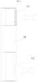
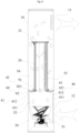
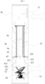
- the air conditioner cabinet includes a housing 10, a heat exchanger 20, a mixed flow fan 30 and a regulating mechanism 40.
- the housing 10 is provided with an upper air port 11 and a lower air port 12.
- the heat exchanger 20 is disposed in the housing 10 and is located between the upper air port 11 and the lower air port 12.
- the mixed flow fan 30 is disposed in the housing 10.
- the regulating mechanism 40 is disposed in the housing 10, the regulating mechanism 40 is located between the mixed flow fan 30 and the heat exchanger 20, the regulating mechanism 40 has a necking position where the regulating mechanism contracts toward the axis of the housing 10, and the regulating mechanism 40 has a flaring position where the regulating mechanism gradually expands away from the axis of the housing 10, and when the regulating mechanism 40 is located at the necking position, the mixed flow fan 30 can suck external airflow into the housing 10 from the upper air port 11, so as to perform heat exchange with the heat exchanger 20, and then discharges the external airflow from the housing 10 by the lower air port 12.
- the air conditioner cabinet with the mixed flow fan can realize a mode of air inflow at the upper air port and air outflow at the lower air port, or, the air conditioner cabinet realizes a mode of air outflow at the upper air port and air inflow at the lower air port.
- the mode of air outflow at the upper air port and air inflow at the lower air port is utilized, and when the air conditioner cabinet is in a heating mode, the mode of air inflow at the upper air port and air outflow at the lower air port is utilized, the problem of indoor heat layering can be effectively avoided, the temperature difference of the indoor temperature can be very small in the longitudinal direction, and the utilization rate of the energy generated by the air conditioner cabinet can be effectively improved.
- the mixed flow fan 30 can suck the external airflow into the housing 10 from the lower air port 12, so as to perform heat exchange with the heat exchanger 20, and then discharges the external airflow from the housing 10 by the upper air port 11.
- the air inflow direction and the air outflow direction of the housing can be changed by disposing the regulating mechanism 40 in the housing, this setting can solve the problem in the prior art that the air inflow mode of the housing can only be changed by utilizing a plurality of fans in the housing, and moreover, in this embodiment, the air inflow mode of the housing can be changed without changing the rotation direction of the mixed flow fan 30, such that the practicability of the air conditioner cabinet is effectively improved.
- the air conditioner cabinet includes an air duct.
- the air duct includes a first air duct 51 and a second air duct 52.
- the first air duct 51 is disposed in the housing 10, a first end of the first air duct 51 is communicated with the lower air port 12, a second end of the first air duct 51 is connected with the regulating mechanism 40, the regulating mechanism 40 and the first air duct 51 are enclosed to form the second air duct 52, and the mixed flow fan 30 is disposed in the first air duct 51.
- the sealing property between the regulating mechanism 40 and the first air duct 51 can be improved, so that the airflow at the lower air port 12 can smoothly enter the housing through the second air duct 52, so as to perform heat exchange with the heat exchanger.
- the air duct further includes a third air duct 53 and a fourth air duct 54
- the air conditioner cabinet includes a supporting portion 60.
- the supporting portion 60 is connected with an inner wall of the housing 10.
- the regulating mechanism 40 is located below the supporting portion 60, an overflow channel 70 is disposed on the supporting portion 60, the heat exchanger 20 is connected with the supporting portion 60, the heat exchanger 20 is of a hollow structure (that is, as shown in Fig.
- the hollow structure is a hollow cylindrical structure enclosed by a heat exchanger body), the hollow structure is communicated with the second air duct 52 through the overflow channel 70, so as to form the third air duct 53, an outer surface of the heat exchanger 20 is disposed at a distance from the housing 10, so as to form the fourth air duct 54, and the fourth air duct 54 is communicated with the upper air port 11 and the third air duct 53.
- the installation stability of the heat exchanger can be effectively improved, the airflow at the outside of the housing can also enter the fourth air channel 54 from the third air duct 53 effectively and conveniently, or, the airflow at the outside of the housing can enter the third air duct 53 from the fourth air duct 53 conveniently.
- a water pan 61 is disposed on the supporting portion 60.
- the water pan 61 is connected with the housing 10, the overflow channel 70 is formed on the water pan 61, and the water pan 61 is used for collecting the condensed water generated by the heat exchanger 20.
- the heat exchanger 20 is of a barrel-shaped structure with an opening at one end, an open end of the heat exchanger 20 is connected with the water pan 61, an inner diameter of the open end of the heat exchanger 20 is greater than an inner diameter of the overflow channel 70, and an airflow in the third air duct 53 exchanges heat through a side wall of the heat exchanger 20 and then flows into the fourth air duct 54, or, an airflow in the fourth air duct 54 can exchanges heat through a side wall of the heat exchanger 20 and then flows into the third air duct 53.
- the annular fourth air channel 54 is formed between the outer surface of the heat exchanger 20 and the inner wall of the housing.
- a part of the side wall of the heat exchanger 20 can also be disposed in an installation manner connected with the side wall of the housing.
- the axis of the heat exchanger 20 is coincided with the axis of the housing in the vertical direction.
- the regulating mechanism 40 includes a first regulating mechanism 41 and a second regulating mechanism 42.
- the first end of the first regulating mechanism 41 is movably connected with the second end of the first air duct 51, a second end of the first regulating mechanism 41 is disposed away from the first air duct 51, the second end of the first regulating mechanism 41 has the necking position close to the axis of the housing 10, and the second end of the first regulating mechanism 41 has the flaring position away from the axis of the housing 10.
- a first end of the second regulating mechanism 42 is movably connected with the water pan 61.
- the second end of the second regulating mechanism 42 has the necking position close to the axis of the housing 10, and the second end of the second regulating mechanism 42 has the flaring position away from the axis (that is, the geometric centerline of the housing 10 in the vertical direction) of the housing 10, when the first regulating mechanism 41 and the second regulating mechanism 42 are both located at the necking positions, the first end of the first regulating mechanism 41 is in contact with the second end of the second regulating mechanism 42, and the first regulating mechanism 41 and the second regulating mechanism 42 are enclosed to form a sealed second air duct 52.
- the structures of the first regulating mechanism 41 and the second regulating mechanism 42 are simple, and a switching operation between different positions can be realized easily.
- the first regulating mechanism 41 and the second regulating mechanism 42 are both located at the flaring positions, the first regulating mechanism 41 is enclosed with at least one of the second regulating mechanism 42, the housing 10, the supporting portion 60 and the water pan 61, so as to form the second air duct 52.
- a sealed channel structure is always enclosed between the regulating mechanism and the housing.
- a cross sectional area of the second air duct 52 is configured to gradually decrease along a direction away from the mixed flow fan 30.
- the cross sectional area of the air duct structure enclosed by the second regulating mechanism 42 is configured to gradually increase along a direction toward the mixed flow fan 30.
- the first regulating mechanism 41 includes a plurality of a first arc-shaped regulating plate 411.
- a first end of each of the plurality of first arc-shaped regulating plate 411 is hinged with an end side wall of the first air duct 51, a second end of each of the plurality of first arc-shaped regulating plate 411 is disposed far away from the first air duct 51, the plurality of first arc-shaped regulating plates 411 are disposed along a circumferential direction of the first air duct 51, and when each of the plurality of first arc-shaped regulating plates 411 is located at the necking position, the plurality of first arc-shaped regulating plates 411 are enclosed to form an annular air duct structure.
- a driving portion can be disposed inside the housing to drive the first arc-shaped regulating plate 411 to rotate.
- the driving portion can drive a single first arc-shaped regulating plate 411 alone, or one driving portion can simultaneously drive the plurality of first arc-shaped regulating plates 411 to rotate.
- the second end of the first arc-shaped regulating plate 411 is provided with a folded edge 412, and the folded edge 412 is bent toward a side of the housing 10.
- the second regulating mechanism 42 includes a plurality of second arc-shaped regulating plates 421.
- a first end of each of the plurality of second arc-shaped regulating plates 421 is hinged with the bottom of a water pan 61, and a second end of each of the plurality of second arc-shaped regulating plate 421 is disposed to be able to rotate around a hinge point of the first end of the second arc-shaped regulating plate 421 and the water pan 61.
- the plurality of second arc-shaped regulating plates are disposed along a circumferential direction of the overflow channel, the plurality of second arc-shaped regulating plates 421 are disposed along a circumferential direction of the overflow channel 70, and when each of the plurality of second arc-shaped regulating plate 421 is located at the necking positions, the plurality of second arc-shaped regulating plates 421 are enclosed to form an annular air duct structure.
- the driving mode of the second regulating mechanism can be the driving mode of the first regulating mechanism.
- the supporting portion 60 further includes an annular supporting platform 62.
- the annular supporting platform 62 is connected with an inner wall of the housing 10.
- the water pan 61 is connected with the annular supporting platform 62 and is located above the annular supporting platform 62, and when the second arc-shaped regulating plate 421 is located at the flaring position, the second end of the second arc-shaped regulating plate 421 is in sealing connection with an inner circumferential surface of the annular supporting platform 62.
- a bottom of the annular supporting platform 62 is provided with an inclined plane, and when the second arc-shaped regulating plate 421 is located at the flaring position, a lower surface of the second arc-shaped regulating plate 421 is parallel to the inclined plane.
- the heat exchanger 20 is of a cylindrical structure, an axis of the heat exchanger 20 is disposed along a vertical direction, and an end of the heat exchanger 20 close to the upper air port 11 is provided with a top plate 21.
- the airflow can only enter or exit through a side wall of the heat exchanger, thereby increasing the heat exchange area between the airflow and the heat exchanger, and improving the heat exchange performance of the air conditioner cabinet.
- the heat exchanger is an evaporator.
- the air conditioner cabinet with this structure can realize the selection of comfortable air outflow function of upper and lower convection, optimize the distribution of an indoor temperature field, and improve the energy utilization efficiency.
- one air port is disposed above and below the vertical air conditioner cabinet respectively, the internal structure is provided with a mixed flow fan structure, different air outflow modes of upper and lower convection are realized through the transformation of the internal mechanism by means of utilizing the characteristics of the mixed flow fan, therefore upper and lower circulation convection is realized in the refrigeration and heating modes.
- heat recovery and utilization can be carried out according to the characteristics of cold and hot air, and then the operating mode of the whole machine can be regulated, so as to achieve the effects of energy saving, comfort and power saving.
- the inside of the housing includes a base, a mixed flow fan, an air duct, a water pan, an evaporator, a regulating mechanism, an upper air port, a lower air port and a top cover.
- the mixed flow fan is a fan between a centrifugal fan and an axial flow fan, which can output the effects of axial working and centrifugal working, in-depth research on the mixed flow fan shows that, the mixed flow fan has different output conditions under different internal pressures, in the structure shown in the figure, when the internal regulating mechanism is fully opened, the pressure of the internal channel becomes smaller, then the mixed flow fan will do more work in an axial flow mode, as a result, the fan sucks air from the lower air port and supplies the air upward, the air passes through the evaporator from both sides for heat exchange through a middle through hole position of the water pan, and is finally gathered at the upper air port for air supply.
- the internal regulating mechanism When the internal regulating mechanism is closed to a necking, the pressure in the internal air duct becomes greater, then the mixed flow fan will do more work in a centrifugal mode, such that the fan supplies the air radially and directly from the lower air port next to the fan, resulting in internal air suction, and as a result, a reverse operation mode is realized.
- the air enters from the upper air port, passes through the evaporator from the surrounding to the middle, and enters the air duct from the middle position of the water pan.
- the air is supplied to the lower air port under the driven of the fan, so as to realize the purpose of lower air supply.
- a method for controlling an air conditioner cabinet is provided.
- the method is used for controlling the above-mentioned air conditioner cabinet, and the method includes the following steps: when a heating mode is selected by a controller of the air conditioner cabinet, the regulating mechanism 40 is located at the necking position, the mixed flow fan 30 sucks the external airflow into the housing 10 from the upper air port 11, so as to perform heat exchange with the heat exchanger 20, and then discharges the external airflow from the housing 10 through the lower air port 12; and when a refrigeration mode is selected by the controller, the regulating mechanism 40 is located at the flaring position, the mixed flow fan 30 sucks the external airflow into the housing 10 from the lower air port 12, so as to perform heat exchange with the heat exchanger 20, and then discharges the external airflow from the housing 10 through the upper air port 11.
- the air conditioner cabinet further includes an air supply mode, when the air supply mode is selected by the controller, the regulating mechanism 40 is located at the necking position, the mixed flow fan 30 sucks the external airflow into the housing 10 from the upper air port 11, and then discharges the external airflow from the housing 10 through the lower air port 12, or, when the air supply mode is selected by the controller, the regulating mechanism 40 is located at the flaring position, the mixed flow fan 30 sucks the external airflow into the housing 10 from the lower air port 12, and then discharges the external airflow from the housing 10 through the upper air port 11, and the heat exchanger 20 is in a non-working state in the air supply mode, that is, the heat exchanger does not perform heat exchange work.
- spatially relative terms can be used here, for example, “on”, “above”, “on the surface of”, “on the top” and the like are used for describing the spatial positional relationship between one device or feature and other devices or features shown in the figure. It should be understood that, the spatially relative terms are intended to encompass different orientations in use or operation other than the orientation of the device described in the figure. For example, if the device in the figure is inverted, then it is described as “above other devices or structures", or the device “above other devices or structures” will be positioned as “below other devices or structures” or “under other devices or structures”. Thus, the exemplary term “above” can include two orientations of “above” and “below”. The device can also be positioned in other different ways (rotated by 90 degrees or in other orientations), and the spatially relative description used here is explained accordingly.
Landscapes
- Engineering & Computer Science (AREA)
- Chemical & Material Sciences (AREA)
- Combustion & Propulsion (AREA)
- Mechanical Engineering (AREA)
- General Engineering & Computer Science (AREA)
- Signal Processing (AREA)
- Physics & Mathematics (AREA)
- Fuzzy Systems (AREA)
- Mathematical Physics (AREA)
- Thermal Sciences (AREA)
- Air-Conditioning Room Units, And Self-Contained Units In General (AREA)
- Devices For Blowing Cold Air, Devices For Blowing Warm Air, And Means For Preventing Water Condensation In Air Conditioning Units (AREA)
Claims (13)
- Klimaanlagenschrank, umfassend:ein Gehäuse (10), wobei das Gehäuse (10) mit einem oberen Luftanschluss (11) und einem unteren Luftanschluss (12) bereitgestellt ist;ein Mischstromgebläse (30), wobei das Mischstromgebläse (30) in dem Gehäuse (10) angeordnet ist; undeinen Reguliermechanismus (40), wobei der Reguliermechanismus (40) in dem Gehäuse (10) angeordnet ist, der Reguliermechanismus (40) eine Einschnürungsposition und eine Aufweitungsposition aufweist und, wenn sich der Reguliermechanismus (40) an der Einschnürungsposition befindet, das Mischstromgebläse (30) einen externen Luftstrom in das Gehäuse (10) aus dem oberen Luftanschluss (11) ansaugt und dann den externen Luftstrom aus dem Gehäuse (10) durch den unteren Luftanschluss (12) abführt;dadurch gekennzeichnet, dass:einen Wärmetauscher (20), wobei der Wärmetauscher (20) in dem Gehäuse (10) angeordnet ist und sich zwischen dem oberen Luftanschluss (11) und dem unteren Luftanschluss (12) befindet, sich der Reguliermechanismus (40) zwischen dem Mischstromgebläse (30) und dem Wärmetauscher (20) befindet, der Reguliermechanismus (40) die Einschnürungsposition aufweist, bei der sich der Reguliermechanismus zu einer Achse des Gehäuses (10) hin zusammenzieht, der Reguliermechanismus (40) die Aufweitungsposition aufweist, bei der sich der Reguliermechanismus allmählich von der Achse des Gehäuses (10) weg ausdehnt, und, wenn sich der Reguliermechanismus (40) an der Einschnürungsposition befindet, das Mischstromgebläse (30) den externen Luftstrom in das Gehäuse (10) aus dem oberen Luftanschluss (11) ansaugt, um einen Wärmeaustausch mit dem Wärmetauscher (20) durchzuführen, und dann den externen Luftstrom aus dem Gehäuse (10) durch den unteren Luftanschluss (12) abführt;wobei, wenn sich der Reguliermechanismus (40) an der Aufweitungsposition befindet, das Mischstromgebläse (30) den externen Luftstrom in das Gehäuse (10) aus dem unteren Luftanschluss (12) ansaugt, um einen Wärmeaustausch mit dem Wärmetauscher (20) durchzuführen, und dann den externen Luftstrom aus dem Gehäuse (10) durch den oberen Luftanschluss (11) abführt.
- Klimaanlagenschrank nach Anspruch 1, wobei der Klimaanlagenschrank eine Luftleitung umfasst, die Luftleitung eine erste Luftleitung (51) und eine zweite Luftleitung (52) umfasst, die erste Luftleitung (51) in dem Gehäuse (10) angeordnet ist, ein erstes Ende der ersten Luftleitung (51) mit dem unteren Luftanschluss (12) kommuniziert, ein zweites Ende der ersten Luftleitung (51) mit dem Reguliermechanismus (40) verbunden ist, der Reguliermechanismus (40) und die erste Luftleitung (51) umschlossen sind, um die zweite Luftleitung (52) zu bilden, und das Mischstromgebläse (30) in der ersten Luftleitung (51) angeordnet ist.
- Klimaanlagenschrank nach Anspruch 2, wobei die Luftleitung ferner eine dritte Luftleitung (53) und eine vierte Luftleitung (54) umfasst, wobei der Klimaanlagenschrank Folgendes umfasst:
einen Stützabschnitt (60), wobei der Stützabschnitt (60) mit einer Innenwand des Gehäuses (10) verbunden ist, sich der Reguliermechanismus (40) unter dem Stützabschnitt (60) befindet, ein Überlaufkanal (70) an dem Stützabschnitt (60) angeordnet ist und der Wärmetauscher (20) mit dem Stützabschnitt (60) verbunden ist. - Klimaanlagenschrank nach Anspruch 3, wobei der Wärmetauscher (20) eine hohle Struktur hat, die hohle Struktur mit der zweiten Luftleitung (52) durch den Überlaufkanal (70) kommuniziert, um die dritte Luftleitung (53) zu bilden, eine Außenfläche des Wärmetauschers (20) in einem Abstand zu dem Gehäuse (10) angeordnet ist, um die vierte Luftleitung (54) zu bilden, und die vierte Luftleitung (54) mit dem oberen Luftanschluss (11) und der dritten Luftleitung (53) kommuniziert.
- Klimaanlagenschrank nach Anspruch 3, wobei der Stützabschnitt (60) Folgendes umfasst:
eine Wasserwanne (61), wobei die Wasserwanne (61) mit dem Gehäuse (10) verbunden ist, der Überlaufkanal (70) an der Wasserwanne (61) gebildet ist und die Wasserwanne (61) zum Sammeln von Kondenswasser, das durch den Wärmetauscher (20) erzeugt wurde, verwendet wird. - Klimaanlagenschrank nach Anspruch 5, wobei der Wärmetauscher (20) eine fassförmige Struktur mit einer Öffnung an einem Ende hat, ein offenes Ende des Wärmetauschers (20) mit der Wasserwanne (61) verbunden ist, ein Innendurchmesser des offenen Endes des Wärmetauschers (20) größer als ein Innendurchmesser des Überlaufkanals (70) ist und ein Luftstrom in der dritten Luftleitung (53) Wärme durch eine Seitenwand des Wärmetauschers (20) austauscht und dann in die vierte Luftleitung (54) strömt oder ein Luftstrom in der vierten Luftleitung (54) Wärme durch eine Seitenwand des Wärmetauschers (20) austauscht und dann in die dritte Luftleitung (53) strömt.
- Klimaanlagenschrank nach Anspruch 5, wobei der Reguliermechanismus (40) Folgendes umfasst:einen ersten Reguliermechanismus (41), wobei ein erstes Ende des ersten Reguliermechanismus (41) beweglich mit dem zweiten Ende der ersten Luftleitung (51) verbunden ist, ein zweites Ende des ersten Reguliermechanismus (41) weg von der ersten Luftleitung (51) angeordnet ist, das zweite Ende des ersten Reguliermechanismus (41) die Einschnürungsposition nahe der Achse des Gehäuses (10) aufweist und das zweite Ende des ersten Reguliermechanismus (41) die Aufweitungsposition weg von der Achse des Gehäuses (10) aufweist; undeinen zweiten Reguliermechanismus (42), wobei ein erstes Ende des zweiten Reguliermechanismus (42) beweglich mit der Wasserwanne (61) verbunden ist, ein zweites Ende des zweiten Reguliermechanismus (42) die Einschnürungsposition nahe der Achse des Gehäuses (10) aufweist und das zweite Ende des zweiten Reguliermechanismus (42) die Aufweitungsposition weg von der Achse des Gehäuses (10) aufweist, wenn sich der erste Reguliermechanismus (41) und der zweite Reguliermechanismus (42) beide an den Einschnürungspositionen befinden, das erste Ende des ersten Reguliermechanismus (41) mit dem zweiten Ende des zweiten Reguliermechanismus (42) in Kontakt steht und der erste Reguliermechanismus (41) und der zweite Reguliermechanismus (42) umschlossen sind, um eine abgedichtete zweite Luftleitung (52) zu bilden.
- Klimaanlagenschrank nach Anspruch 7, wobei, wenn sich der erste Reguliermechanismus (41) und der zweite Reguliermechanismus (42) beide an den Aufweitungspositionen befinden, der erste Reguliermechanismus (41) mit mindestens einem von dem zweiten Reguliermechanismus (42), dem Gehäuse (10), dem Stützabschnitt (60) und der Wasserwanne (61) umschlossen sind, um die zweite Luftleitung (52) zu bilden.
- Klimaanlagenschrank nach Anspruch 7, wobei, wenn sich der erste Reguliermechanismus (41) und der zweite Reguliermechanismus (42) beide an den Einschnürungspositionen befinden, ein Querschnittsbereich der zweiten Luftleitung (52) dazu konfiguriert ist, allmählich entlang einer Richtung von dem Mischstromgebläse (30) weg abzunehmen; wenn sich der erste Reguliermechanismus (41) und der zweite Reguliermechanismus (42) beide an den Aufweitungspositionen befinden, ein Querschnittsbereich der Luftleitungsstruktur, die durch den zweiten Reguliermechanismus (42) umschlossen ist, dazu konfiguriert ist, allmählich entlang einer Richtung zu dem Mischstromgebläse (30) hin zuzunehmen.
- Klimaanlagenschrank nach Anspruch 7, wobei der erste Reguliermechanismus (41) Folgendes umfasst:
eine Vielzahl von ersten bogenförmigen Regulierplatten (411), wobei ein erstes Ende jeder der Vielzahl von ersten bogenförmigen Regulierplatten (411) gelenkartig an einer Endseitenwand der ersten Luftleitung (51) angebracht ist, ein zweites Ende jeder der Vielzahl von ersten bogenförmigen Regulierplatten (411) weit weg von der ersten Luftleitung (51) angeordnet ist, die Vielzahl von ersten bogenförmigen Regulierplatten (411) entlang einer Umfangsrichtung der ersten Luftleitung (51) angeordnet sind und, wenn sich jede der Vielzahl von ersten bogenförmigen Regulierplatten (411) an der Einschnürungsposition befindet, die Vielzahl von ersten bogenförmigen Regulierplatten (411) umschlossen sind, um eine ringförmige Luftleitungsstruktur zu bilden. - Klimaanlagenschrank nach Anspruch 7, wobei der zweite Reguliermechanismus (42) Folgendes umfasst:
eine Vielzahl von zweiten bogenförmigen Regulierplatten (421), wobei ein erstes Ende jeder der Vielzahl von zweiten bogenförmigen Regulierplatten (421) gelenkartig an einem Boden der Wasserwanne (61) angebracht ist, ein zweites Ende jeder der Vielzahl von zweiten bogenförmigen Regulierplatten (421) angeordnet ist, um sich um einen Gelenkpunkt des ersten Endes der zweiten bogenförmigen Regulierplatten (421) und der Wasserwanne (61) drehen zu können, die Vielzahl von zweiten bogenförmigen Regulierplatten (421) entlang einer Umfangsrichtung des Überlaufkanals (70) angeordnet sind und, wenn sich jede der Vielzahl von zweiten bogenförmigen Regulierplatten (421) an den Einschnürungspositionen befindet, die Vielzahl von zweiten bogenförmigen Regulierplatten (421) umschlossen sind, um eine ringförmige Luftleitungsstruktur zu bilden. - Verfahren zum Steuern eines Klimaanlagenschranks, wobei das Verfahren zum Steuern des Klimaanlagenschranks nach einem der Ansprüche 1-11 verwendet wird, wobei das Verfahren folgende Schritte umfasst:wenn ein Heizmodus durch eine Steuerung des Klimaanlagenschranks ausgewählt wird, sich der Reguliermechanismus (40) an der Einschnürungsposition befindet, das Mischstromgebläse (30) den externen Luftstrom in das Gehäuse (10) aus dem oberen Luftanschluss (11) ansaugt, um einen Wärmeaustausch mit dem Wärmetauscher (20) durchzuführen, und dann den externen Luftstrom aus dem Gehäuse (10) durch den unteren Luftanschluss (12) abführt; undwenn ein Kühlmodus durch die Steuerung ausgewählt wird, sich der Reguliermechanismus (40) an der Aufweitungsposition befindet, das Mischstromgebläse (30) den externen Luftstrom in das Gehäuse (10) aus dem unteren Luftanschluss (12) ansaugt, um einen Wärmeaustausch mit dem Wärmetauscher (20) durchzuführen, und dann den externen Luftstrom aus dem Gehäuse (10) durch den oberen Luftanschluss (11) abführt.
- Verfahren nach Anspruch 12, wobei der Klimaanlagenschrank ferner einen Luftzufuhrmodus umfasst, wenn der Luftzufuhrmodus durch die Steuerung ausgewählt wird, sich der Reguliermechanismus (40) an der Einschnürungsposition befindet, das Mischstromgebläse (30) den externen Luftstrom in das Gehäuse (10) aus dem oberen Luftanschluss (11) ansaugt und dann den externen Luftstrom aus dem Gehäuse (10) durch den unteren Luftanschluss (12) abführt, oder, wenn der Luftzufuhrmodus durch die Steuerung ausgewählt wird, sich der Reguliermechanismus (40) an der Aufweitungsposition befindet, das Mischstromgebläse (30) den externen Luftstrom in das Gehäuse (10) aus dem unteren Luftanschluss (12) ansaugt und dann den externen Luftstrom aus dem Gehäuse (10) durch den oberen Luftanschluss (11) abführt,
wobei der Wärmetauscher (20) in einem nicht arbeitenden Zustand in dem Luftzufuhrmodus ist.
Applications Claiming Priority (2)
| Application Number | Priority Date | Filing Date | Title |
|---|---|---|---|
| CN201910713842.4A CN112303728B (zh) | 2019-08-02 | 2019-08-02 | 空调柜机及控制方法 |
| PCT/CN2020/095224 WO2021022897A1 (zh) | 2019-08-02 | 2020-06-09 | 空调柜机及控制方法 |
Publications (3)
| Publication Number | Publication Date |
|---|---|
| EP4008971A1 EP4008971A1 (de) | 2022-06-08 |
| EP4008971A4 EP4008971A4 (de) | 2022-09-07 |
| EP4008971B1 true EP4008971B1 (de) | 2024-09-18 |
Family
ID=74485250
Family Applications (1)
| Application Number | Title | Priority Date | Filing Date |
|---|---|---|---|
| EP20849279.3A Active EP4008971B1 (de) | 2019-08-02 | 2020-06-09 | Schrankklimaanlage und steuerungsverfahren |
Country Status (3)
| Country | Link |
|---|---|
| EP (1) | EP4008971B1 (de) |
| CN (1) | CN112303728B (de) |
| WO (1) | WO2021022897A1 (de) |
Families Citing this family (3)
| Publication number | Priority date | Publication date | Assignee | Title |
|---|---|---|---|---|
| CN113606666B (zh) * | 2021-07-30 | 2025-02-18 | 珠海格力电器股份有限公司 | 空调的送风结构及空调 |
| CN117167832B (zh) * | 2023-10-07 | 2025-08-05 | 珠海格力电器股份有限公司 | 电加热组件、空调器及电加热组件控制方法 |
| CN119436274B (zh) * | 2024-12-20 | 2025-10-24 | 珠海格力电器股份有限公司 | 柜式空调器及其控制方法 |
Family Cites Families (13)
| Publication number | Priority date | Publication date | Assignee | Title |
|---|---|---|---|---|
| JPH0331621A (ja) * | 1989-06-28 | 1991-02-12 | Matsushita Refrig Co Ltd | 空気調和機 |
| KR920007088Y1 (ko) * | 1990-07-28 | 1992-10-02 | 삼성전자 주식회사 | 냉난방 겸용 공조기 |
| CN2303198Y (zh) * | 1997-03-18 | 1999-01-06 | 广东美的集团股份有限公司 | 分体落地式空调器 |
| JPH11230380A (ja) * | 1998-02-17 | 1999-08-27 | Hitachi Plant Eng & Constr Co Ltd | 風量調整ダンパ |
| JP2005315531A (ja) * | 2004-04-30 | 2005-11-10 | Fujitsu General Ltd | 空気調和機の室内機 |
| CN103776203B (zh) * | 2012-10-17 | 2017-02-01 | 珠海格力电器股份有限公司 | 筒状蒸发器及具有其的空调柜机 |
| JP5720657B2 (ja) * | 2012-11-02 | 2015-05-20 | ダイキン工業株式会社 | 床置き型空調室内機 |
| CN105972700B (zh) * | 2016-06-27 | 2018-11-27 | 珠海格力电器股份有限公司 | 空调器及其风管式空调室内机 |
| CN106440056A (zh) * | 2016-11-17 | 2017-02-22 | 珠海格力电器股份有限公司 | 空调柜机 |
| CN206361810U (zh) * | 2016-11-17 | 2017-07-28 | 珠海格力电器股份有限公司 | 空调柜机 |
| CN208920209U (zh) * | 2018-06-19 | 2019-05-31 | 青岛海尔空调器有限总公司 | 柜式空调室内机 |
| CN209013431U (zh) * | 2018-10-30 | 2019-06-21 | 珠海格力电器股份有限公司 | 一种空调器壳体 |
| CN210740546U (zh) * | 2019-08-02 | 2020-06-12 | 珠海格力电器股份有限公司 | 空调柜机 |
-
2019
- 2019-08-02 CN CN201910713842.4A patent/CN112303728B/zh active Active
-
2020
- 2020-06-09 WO PCT/CN2020/095224 patent/WO2021022897A1/zh not_active Ceased
- 2020-06-09 EP EP20849279.3A patent/EP4008971B1/de active Active
Also Published As
| Publication number | Publication date |
|---|---|
| CN112303728B (zh) | 2025-05-16 |
| EP4008971A1 (de) | 2022-06-08 |
| WO2021022897A1 (zh) | 2021-02-11 |
| EP4008971A4 (de) | 2022-09-07 |
| CN112303728A (zh) | 2021-02-02 |
Similar Documents
| Publication | Publication Date | Title |
|---|---|---|
| EP3721143B1 (de) | Klimaanlage | |
| EP3412979B1 (de) | Klimatisierungsvorrichtung | |
| EP4008971B1 (de) | Schrankklimaanlage und steuerungsverfahren | |
| CN110360622A (zh) | 厨房空气调节系统 | |
| CN105423510A (zh) | 风道组件及具有其的空调器 | |
| CN110792635B (zh) | 一种散热风机及安装有该风机的厨房空气调节系统 | |
| CN210511923U (zh) | 空调柜机 | |
| CN211650477U (zh) | 空调内机和空调器 | |
| CN114245679A (zh) | 空调器及其控制方法 | |
| CN210511922U (zh) | 空调柜机 | |
| CN120368483A (zh) | 空调器的控制方法 | |
| CN210740546U (zh) | 空调柜机 | |
| CN205783329U (zh) | 吸顶式空调室内机 | |
| CN215570832U (zh) | 一种室内空调器 | |
| JP2020510184A (ja) | 熱交換ユニット | |
| JP7741438B1 (ja) | 熱交換ユニットおよび空気調和装置 | |
| CN221505135U (zh) | 分区出风装置及空调 | |
| CN223294924U (zh) | 一种空调 | |
| CN216281752U (zh) | 一种空调器 | |
| CN215929820U (zh) | 一种室内空调器 | |
| CN224201774U (zh) | 空调室内机及空调机组 | |
| CN218379612U (zh) | 空调室内机 | |
| CN215570833U (zh) | 一种室内空调器 | |
| CN110793131A (zh) | 一种散热蜗壳及安装有该散热蜗壳的厨房空调系统 | |
| CN110792614A (zh) | 一种离心风机、安装有该风机吸油烟机及厨房空调系统 |
Legal Events
| Date | Code | Title | Description |
|---|---|---|---|
| STAA | Information on the status of an ep patent application or granted ep patent |
Free format text: STATUS: THE INTERNATIONAL PUBLICATION HAS BEEN MADE |
|
| PUAI | Public reference made under article 153(3) epc to a published international application that has entered the european phase |
Free format text: ORIGINAL CODE: 0009012 |
|
| STAA | Information on the status of an ep patent application or granted ep patent |
Free format text: STATUS: REQUEST FOR EXAMINATION WAS MADE |
|
| 17P | Request for examination filed |
Effective date: 20211216 |
|
| AK | Designated contracting states |
Kind code of ref document: A1 Designated state(s): AL AT BE BG CH CY CZ DE DK EE ES FI FR GB GR HR HU IE IS IT LI LT LU LV MC MK MT NL NO PL PT RO RS SE SI SK SM TR |
|
| A4 | Supplementary search report drawn up and despatched |
Effective date: 20220805 |
|
| RIC1 | Information provided on ipc code assigned before grant |
Ipc: F24F 7/00 20210101ALI20220801BHEP Ipc: F24F 13/20 20060101ALI20220801BHEP Ipc: F24F 13/10 20060101ALI20220801BHEP Ipc: F24F 13/22 20060101ALI20220801BHEP Ipc: F24F 13/30 20060101ALI20220801BHEP Ipc: F24F 11/65 20180101ALI20220801BHEP Ipc: F24F 11/67 20180101ALI20220801BHEP Ipc: F24F 1/0063 20190101ALI20220801BHEP Ipc: F24F 1/0018 20190101ALI20220801BHEP Ipc: F24F 1/0014 20190101AFI20220801BHEP |
|
| DAV | Request for validation of the european patent (deleted) | ||
| DAX | Request for extension of the european patent (deleted) | ||
| P01 | Opt-out of the competence of the unified patent court (upc) registered |
Effective date: 20230530 |
|
| GRAP | Despatch of communication of intention to grant a patent |
Free format text: ORIGINAL CODE: EPIDOSNIGR1 |
|
| STAA | Information on the status of an ep patent application or granted ep patent |
Free format text: STATUS: GRANT OF PATENT IS INTENDED |
|
| INTG | Intention to grant announced |
Effective date: 20240712 |
|
| GRAS | Grant fee paid |
Free format text: ORIGINAL CODE: EPIDOSNIGR3 |
|
| GRAA | (expected) grant |
Free format text: ORIGINAL CODE: 0009210 |
|
| STAA | Information on the status of an ep patent application or granted ep patent |
Free format text: STATUS: THE PATENT HAS BEEN GRANTED |
|
| AK | Designated contracting states |
Kind code of ref document: B1 Designated state(s): AL AT BE BG CH CY CZ DE DK EE ES FI FR GB GR HR HU IE IS IT LI LT LU LV MC MK MT NL NO PL PT RO RS SE SI SK SM TR |
|
| REG | Reference to a national code |
Ref country code: GB Ref legal event code: FG4D |
|
| REG | Reference to a national code |
Ref country code: CH Ref legal event code: EP |
|
| REG | Reference to a national code |
Ref country code: IE Ref legal event code: FG4D |
|
| REG | Reference to a national code |
Ref country code: DE Ref legal event code: R096 Ref document number: 602020038097 Country of ref document: DE |
|
| REG | Reference to a national code |
Ref country code: LT Ref legal event code: MG9D |
|
| PG25 | Lapsed in a contracting state [announced via postgrant information from national office to epo] |
Ref country code: NO Free format text: LAPSE BECAUSE OF FAILURE TO SUBMIT A TRANSLATION OF THE DESCRIPTION OR TO PAY THE FEE WITHIN THE PRESCRIBED TIME-LIMIT Effective date: 20241218 |
|
| PG25 | Lapsed in a contracting state [announced via postgrant information from national office to epo] |
Ref country code: GR Free format text: LAPSE BECAUSE OF FAILURE TO SUBMIT A TRANSLATION OF THE DESCRIPTION OR TO PAY THE FEE WITHIN THE PRESCRIBED TIME-LIMIT Effective date: 20241219 Ref country code: FI Free format text: LAPSE BECAUSE OF FAILURE TO SUBMIT A TRANSLATION OF THE DESCRIPTION OR TO PAY THE FEE WITHIN THE PRESCRIBED TIME-LIMIT Effective date: 20240918 |
|
| PG25 | Lapsed in a contracting state [announced via postgrant information from national office to epo] |
Ref country code: BG Free format text: LAPSE BECAUSE OF FAILURE TO SUBMIT A TRANSLATION OF THE DESCRIPTION OR TO PAY THE FEE WITHIN THE PRESCRIBED TIME-LIMIT Effective date: 20240918 |
|
| PG25 | Lapsed in a contracting state [announced via postgrant information from national office to epo] |
Ref country code: LV Free format text: LAPSE BECAUSE OF FAILURE TO SUBMIT A TRANSLATION OF THE DESCRIPTION OR TO PAY THE FEE WITHIN THE PRESCRIBED TIME-LIMIT Effective date: 20240918 |
|
| PG25 | Lapsed in a contracting state [announced via postgrant information from national office to epo] |
Ref country code: HR Free format text: LAPSE BECAUSE OF FAILURE TO SUBMIT A TRANSLATION OF THE DESCRIPTION OR TO PAY THE FEE WITHIN THE PRESCRIBED TIME-LIMIT Effective date: 20240918 |
|
| REG | Reference to a national code |
Ref country code: NL Ref legal event code: MP Effective date: 20240918 |
|
| PG25 | Lapsed in a contracting state [announced via postgrant information from national office to epo] |
Ref country code: RS Free format text: LAPSE BECAUSE OF FAILURE TO SUBMIT A TRANSLATION OF THE DESCRIPTION OR TO PAY THE FEE WITHIN THE PRESCRIBED TIME-LIMIT Effective date: 20241218 |
|
| PG25 | Lapsed in a contracting state [announced via postgrant information from national office to epo] |
Ref country code: RS Free format text: LAPSE BECAUSE OF FAILURE TO SUBMIT A TRANSLATION OF THE DESCRIPTION OR TO PAY THE FEE WITHIN THE PRESCRIBED TIME-LIMIT Effective date: 20241218 Ref country code: NO Free format text: LAPSE BECAUSE OF FAILURE TO SUBMIT A TRANSLATION OF THE DESCRIPTION OR TO PAY THE FEE WITHIN THE PRESCRIBED TIME-LIMIT Effective date: 20241218 Ref country code: LV Free format text: LAPSE BECAUSE OF FAILURE TO SUBMIT A TRANSLATION OF THE DESCRIPTION OR TO PAY THE FEE WITHIN THE PRESCRIBED TIME-LIMIT Effective date: 20240918 Ref country code: HR Free format text: LAPSE BECAUSE OF FAILURE TO SUBMIT A TRANSLATION OF THE DESCRIPTION OR TO PAY THE FEE WITHIN THE PRESCRIBED TIME-LIMIT Effective date: 20240918 Ref country code: GR Free format text: LAPSE BECAUSE OF FAILURE TO SUBMIT A TRANSLATION OF THE DESCRIPTION OR TO PAY THE FEE WITHIN THE PRESCRIBED TIME-LIMIT Effective date: 20241219 Ref country code: FI Free format text: LAPSE BECAUSE OF FAILURE TO SUBMIT A TRANSLATION OF THE DESCRIPTION OR TO PAY THE FEE WITHIN THE PRESCRIBED TIME-LIMIT Effective date: 20240918 Ref country code: BG Free format text: LAPSE BECAUSE OF FAILURE TO SUBMIT A TRANSLATION OF THE DESCRIPTION OR TO PAY THE FEE WITHIN THE PRESCRIBED TIME-LIMIT Effective date: 20240918 |
|
| REG | Reference to a national code |
Ref country code: AT Ref legal event code: MK05 Ref document number: 1724990 Country of ref document: AT Kind code of ref document: T Effective date: 20240918 |
|
| PG25 | Lapsed in a contracting state [announced via postgrant information from national office to epo] |
Ref country code: NL Free format text: LAPSE BECAUSE OF FAILURE TO SUBMIT A TRANSLATION OF THE DESCRIPTION OR TO PAY THE FEE WITHIN THE PRESCRIBED TIME-LIMIT Effective date: 20240918 |
|
| PG25 | Lapsed in a contracting state [announced via postgrant information from national office to epo] |
Ref country code: PT Free format text: LAPSE BECAUSE OF FAILURE TO SUBMIT A TRANSLATION OF THE DESCRIPTION OR TO PAY THE FEE WITHIN THE PRESCRIBED TIME-LIMIT Effective date: 20250120 Ref country code: IS Free format text: LAPSE BECAUSE OF FAILURE TO SUBMIT A TRANSLATION OF THE DESCRIPTION OR TO PAY THE FEE WITHIN THE PRESCRIBED TIME-LIMIT Effective date: 20250118 |
|
| PG25 | Lapsed in a contracting state [announced via postgrant information from national office to epo] |
Ref country code: RO Free format text: LAPSE BECAUSE OF FAILURE TO SUBMIT A TRANSLATION OF THE DESCRIPTION OR TO PAY THE FEE WITHIN THE PRESCRIBED TIME-LIMIT Effective date: 20240918 Ref country code: SM Free format text: LAPSE BECAUSE OF FAILURE TO SUBMIT A TRANSLATION OF THE DESCRIPTION OR TO PAY THE FEE WITHIN THE PRESCRIBED TIME-LIMIT Effective date: 20240918 |
|
| PG25 | Lapsed in a contracting state [announced via postgrant information from national office to epo] |
Ref country code: ES Free format text: LAPSE BECAUSE OF FAILURE TO SUBMIT A TRANSLATION OF THE DESCRIPTION OR TO PAY THE FEE WITHIN THE PRESCRIBED TIME-LIMIT Effective date: 20240918 |
|
| PG25 | Lapsed in a contracting state [announced via postgrant information from national office to epo] |
Ref country code: EE Free format text: LAPSE BECAUSE OF FAILURE TO SUBMIT A TRANSLATION OF THE DESCRIPTION OR TO PAY THE FEE WITHIN THE PRESCRIBED TIME-LIMIT Effective date: 20240918 Ref country code: AT Free format text: LAPSE BECAUSE OF FAILURE TO SUBMIT A TRANSLATION OF THE DESCRIPTION OR TO PAY THE FEE WITHIN THE PRESCRIBED TIME-LIMIT Effective date: 20240918 |
|
| PG25 | Lapsed in a contracting state [announced via postgrant information from national office to epo] |
Ref country code: CZ Free format text: LAPSE BECAUSE OF FAILURE TO SUBMIT A TRANSLATION OF THE DESCRIPTION OR TO PAY THE FEE WITHIN THE PRESCRIBED TIME-LIMIT Effective date: 20240918 Ref country code: PL Free format text: LAPSE BECAUSE OF FAILURE TO SUBMIT A TRANSLATION OF THE DESCRIPTION OR TO PAY THE FEE WITHIN THE PRESCRIBED TIME-LIMIT Effective date: 20240918 |
|
| PG25 | Lapsed in a contracting state [announced via postgrant information from national office to epo] |
Ref country code: IT Free format text: LAPSE BECAUSE OF FAILURE TO SUBMIT A TRANSLATION OF THE DESCRIPTION OR TO PAY THE FEE WITHIN THE PRESCRIBED TIME-LIMIT Effective date: 20240918 Ref country code: SK Free format text: LAPSE BECAUSE OF FAILURE TO SUBMIT A TRANSLATION OF THE DESCRIPTION OR TO PAY THE FEE WITHIN THE PRESCRIBED TIME-LIMIT Effective date: 20240918 |
|
| REG | Reference to a national code |
Ref country code: DE Ref legal event code: R097 Ref document number: 602020038097 Country of ref document: DE |
|
| PG25 | Lapsed in a contracting state [announced via postgrant information from national office to epo] |
Ref country code: DK Free format text: LAPSE BECAUSE OF FAILURE TO SUBMIT A TRANSLATION OF THE DESCRIPTION OR TO PAY THE FEE WITHIN THE PRESCRIBED TIME-LIMIT Effective date: 20240918 |
|
| PLBE | No opposition filed within time limit |
Free format text: ORIGINAL CODE: 0009261 |
|
| STAA | Information on the status of an ep patent application or granted ep patent |
Free format text: STATUS: NO OPPOSITION FILED WITHIN TIME LIMIT |
|
| 26N | No opposition filed |
Effective date: 20250619 |
|
| PG25 | Lapsed in a contracting state [announced via postgrant information from national office to epo] |
Ref country code: SE Free format text: LAPSE BECAUSE OF FAILURE TO SUBMIT A TRANSLATION OF THE DESCRIPTION OR TO PAY THE FEE WITHIN THE PRESCRIBED TIME-LIMIT Effective date: 20240918 |
|
| PGFP | Annual fee paid to national office [announced via postgrant information from national office to epo] |
Ref country code: DE Payment date: 20250725 Year of fee payment: 6 |
|
| REG | Reference to a national code |
Ref country code: CH Ref legal event code: H13 Free format text: ST27 STATUS EVENT CODE: U-0-0-H10-H13 (AS PROVIDED BY THE NATIONAL OFFICE) Effective date: 20260127 |
|
| PG25 | Lapsed in a contracting state [announced via postgrant information from national office to epo] |
Ref country code: MC Free format text: LAPSE BECAUSE OF FAILURE TO SUBMIT A TRANSLATION OF THE DESCRIPTION OR TO PAY THE FEE WITHIN THE PRESCRIBED TIME-LIMIT Effective date: 20240918 |
|
| PG25 | Lapsed in a contracting state [announced via postgrant information from national office to epo] |
Ref country code: LU Free format text: LAPSE BECAUSE OF NON-PAYMENT OF DUE FEES Effective date: 20250609 |
|
| GBPC | Gb: european patent ceased through non-payment of renewal fee |
Effective date: 20250609 |
|
| REG | Reference to a national code |
Ref country code: BE Ref legal event code: MM Effective date: 20250630 |
|
| PG25 | Lapsed in a contracting state [announced via postgrant information from national office to epo] |
Ref country code: GB Free format text: LAPSE BECAUSE OF NON-PAYMENT OF DUE FEES Effective date: 20250609 |
|
| PG25 | Lapsed in a contracting state [announced via postgrant information from national office to epo] |
Ref country code: IE Free format text: LAPSE BECAUSE OF NON-PAYMENT OF DUE FEES Effective date: 20250609 |
|
| PG25 | Lapsed in a contracting state [announced via postgrant information from national office to epo] |
Ref country code: BE Free format text: LAPSE BECAUSE OF NON-PAYMENT OF DUE FEES Effective date: 20250630 |
|
| PG25 | Lapsed in a contracting state [announced via postgrant information from national office to epo] |
Ref country code: FR Free format text: LAPSE BECAUSE OF NON-PAYMENT OF DUE FEES Effective date: 20250630 |
|
| PG25 | Lapsed in a contracting state [announced via postgrant information from national office to epo] |
Ref country code: CH Free format text: LAPSE BECAUSE OF NON-PAYMENT OF DUE FEES Effective date: 20250630 |