EP4007683B1 - Bauteil aus einem werkstoff, der überwiegend aus nachwachsenden rohstoffen besteht, mit mindestens einem verdichteten bereich sowie verfahren und werkzeug zum herstellen des verdichteten bereiches - Google Patents
Bauteil aus einem werkstoff, der überwiegend aus nachwachsenden rohstoffen besteht, mit mindestens einem verdichteten bereich sowie verfahren und werkzeug zum herstellen des verdichteten bereiches Download PDFInfo
- Publication number
- EP4007683B1 EP4007683B1 EP20761135.1A EP20761135A EP4007683B1 EP 4007683 B1 EP4007683 B1 EP 4007683B1 EP 20761135 A EP20761135 A EP 20761135A EP 4007683 B1 EP4007683 B1 EP 4007683B1
- Authority
- EP
- European Patent Office
- Prior art keywords
- component
- mandrel
- hole
- diameter
- tool
- Prior art date
- Legal status (The legal status is an assumption and is not a legal conclusion. Google has not performed a legal analysis and makes no representation as to the accuracy of the status listed.)
- Active
Links
Images


Classifications
-
- B—PERFORMING OPERATIONS; TRANSPORTING
- B27—WORKING OR PRESERVING WOOD OR SIMILAR MATERIAL; NAILING OR STAPLING MACHINES IN GENERAL
- B27D—WORKING VENEER OR PLYWOOD
- B27D3/00—Veneer presses; Press plates; Plywood presses
- B27D3/02—Veneer presses; Press plates; Plywood presses with a plurality of press plates, i.e. multi- platen hot presses
-
- B—PERFORMING OPERATIONS; TRANSPORTING
- B27—WORKING OR PRESERVING WOOD OR SIMILAR MATERIAL; NAILING OR STAPLING MACHINES IN GENERAL
- B27M—WORKING OF WOOD NOT PROVIDED FOR IN SUBCLASSES B27B - B27L; MANUFACTURE OF SPECIFIC WOODEN ARTICLES
- B27M1/00—Working of wood not provided for in subclasses B27B - B27L, e.g. by stretching
- B27M1/04—Working of wood not provided for in subclasses B27B - B27L, e.g. by stretching by punching out
-
- B—PERFORMING OPERATIONS; TRANSPORTING
- B29—WORKING OF PLASTICS; WORKING OF SUBSTANCES IN A PLASTIC STATE IN GENERAL
- B29C—SHAPING OR JOINING OF PLASTICS; SHAPING OF MATERIAL IN A PLASTIC STATE, NOT OTHERWISE PROVIDED FOR; AFTER-TREATMENT OF THE SHAPED PRODUCTS, e.g. REPAIRING
- B29C70/00—Shaping composites, i.e. plastics material comprising reinforcements, fillers or preformed parts, e.g. inserts
- B29C70/04—Shaping composites, i.e. plastics material comprising reinforcements, fillers or preformed parts, e.g. inserts comprising reinforcements only, e.g. self-reinforcing plastics
- B29C70/28—Shaping operations therefor
- B29C70/54—Component parts, details or accessories; Auxiliary operations, e.g. feeding or storage of prepregs or SMC after impregnation or during ageing
- B29C70/545—Perforating, cutting or machining during or after moulding
-
- B—PERFORMING OPERATIONS; TRANSPORTING
- B32—LAYERED PRODUCTS
- B32B—LAYERED PRODUCTS, i.e. PRODUCTS BUILT-UP OF STRATA OF FLAT OR NON-FLAT, e.g. CELLULAR OR HONEYCOMB, FORM
- B32B15/00—Layered products comprising a layer of metal
- B32B15/04—Layered products comprising a layer of metal comprising metal as the main or only constituent of a layer, which is next to another layer of the same or of a different material
- B32B15/10—Layered products comprising a layer of metal comprising metal as the main or only constituent of a layer, which is next to another layer of the same or of a different material of wood
-
- B—PERFORMING OPERATIONS; TRANSPORTING
- B32—LAYERED PRODUCTS
- B32B—LAYERED PRODUCTS, i.e. PRODUCTS BUILT-UP OF STRATA OF FLAT OR NON-FLAT, e.g. CELLULAR OR HONEYCOMB, FORM
- B32B21/00—Layered products comprising a layer of wood, e.g. wood board, veneer, wood particle board
- B32B21/04—Layered products comprising a layer of wood, e.g. wood board, veneer, wood particle board comprising wood as the main or only constituent of a layer, which is next to another layer of the same or of a different material
- B32B21/042—Layered products comprising a layer of wood, e.g. wood board, veneer, wood particle board comprising wood as the main or only constituent of a layer, which is next to another layer of the same or of a different material of wood
-
- B—PERFORMING OPERATIONS; TRANSPORTING
- B32—LAYERED PRODUCTS
- B32B—LAYERED PRODUCTS, i.e. PRODUCTS BUILT-UP OF STRATA OF FLAT OR NON-FLAT, e.g. CELLULAR OR HONEYCOMB, FORM
- B32B21/00—Layered products comprising a layer of wood, e.g. wood board, veneer, wood particle board
- B32B21/04—Layered products comprising a layer of wood, e.g. wood board, veneer, wood particle board comprising wood as the main or only constituent of a layer, which is next to another layer of the same or of a different material
- B32B21/06—Layered products comprising a layer of wood, e.g. wood board, veneer, wood particle board comprising wood as the main or only constituent of a layer, which is next to another layer of the same or of a different material of paper or cardboard
-
- B—PERFORMING OPERATIONS; TRANSPORTING
- B32—LAYERED PRODUCTS
- B32B—LAYERED PRODUCTS, i.e. PRODUCTS BUILT-UP OF STRATA OF FLAT OR NON-FLAT, e.g. CELLULAR OR HONEYCOMB, FORM
- B32B21/00—Layered products comprising a layer of wood, e.g. wood board, veneer, wood particle board
- B32B21/04—Layered products comprising a layer of wood, e.g. wood board, veneer, wood particle board comprising wood as the main or only constituent of a layer, which is next to another layer of the same or of a different material
- B32B21/08—Layered products comprising a layer of wood, e.g. wood board, veneer, wood particle board comprising wood as the main or only constituent of a layer, which is next to another layer of the same or of a different material of synthetic resin
-
- B—PERFORMING OPERATIONS; TRANSPORTING
- B32—LAYERED PRODUCTS
- B32B—LAYERED PRODUCTS, i.e. PRODUCTS BUILT-UP OF STRATA OF FLAT OR NON-FLAT, e.g. CELLULAR OR HONEYCOMB, FORM
- B32B3/00—Layered products comprising a layer with external or internal discontinuities or unevennesses, or a layer of non-planar shape; Layered products comprising a layer having particular features of form
- B32B3/26—Layered products comprising a layer with external or internal discontinuities or unevennesses, or a layer of non-planar shape; Layered products comprising a layer having particular features of form characterised by a particular shape of the outline of the cross-section of a continuous layer; characterised by a layer with cavities or internal voids ; characterised by an apertured layer
- B32B3/266—Layered products comprising a layer with external or internal discontinuities or unevennesses, or a layer of non-planar shape; Layered products comprising a layer having particular features of form characterised by a particular shape of the outline of the cross-section of a continuous layer; characterised by a layer with cavities or internal voids ; characterised by an apertured layer characterised by an apertured layer, the apertures going through the whole thickness of the layer, e.g. expanded metal, perforated layer, slit layer regular cells B32B3/12
-
- B—PERFORMING OPERATIONS; TRANSPORTING
- B27—WORKING OR PRESERVING WOOD OR SIMILAR MATERIAL; NAILING OR STAPLING MACHINES IN GENERAL
- B27M—WORKING OF WOOD NOT PROVIDED FOR IN SUBCLASSES B27B - B27L; MANUFACTURE OF SPECIFIC WOODEN ARTICLES
- B27M1/00—Working of wood not provided for in subclasses B27B - B27L, e.g. by stretching
- B27M1/02—Working of wood not provided for in subclasses B27B - B27L, e.g. by stretching by compressing
-
- B—PERFORMING OPERATIONS; TRANSPORTING
- B27—WORKING OR PRESERVING WOOD OR SIMILAR MATERIAL; NAILING OR STAPLING MACHINES IN GENERAL
- B27M—WORKING OF WOOD NOT PROVIDED FOR IN SUBCLASSES B27B - B27L; MANUFACTURE OF SPECIFIC WOODEN ARTICLES
- B27M3/00—Manufacture or reconditioning of specific semi-finished or finished articles
- B27M3/0013—Manufacture or reconditioning of specific semi-finished or finished articles of composite or compound articles
- B27M3/0026—Manufacture or reconditioning of specific semi-finished or finished articles of composite or compound articles characterised by oblong elements connected laterally
- B27M3/004—Manufacture or reconditioning of specific semi-finished or finished articles of composite or compound articles characterised by oblong elements connected laterally by nails, staples or screws
Definitions
- the invention relates to a component made of a material consisting predominantly of renewable raw materials, with at least one compacted area, as well as a method and a tool for producing the compacted area and is used in particular for fatigue-resistant screw connections.
- a tapered screw for foamed plastics is described. This is a connection in a plastic with a defined elasticity.
- the screw thread is tapered. When the thread is screwed in, the material is not destroyed, but rather displaced and compressed. The deeper the thread is screwed in, the larger the diameter of the cone and the more material is displaced. This means that the restoring torque required for screwing in increases and thus the contact force that develops between the parts to be connected also increases. This creates a large surface pressure between them, which leads to a resilient connection.
- WO 2016 162 111 A1 A reversible connection between machine parts is described.
- a flowable medium is introduced into a cavity of a component and this is then closed.
- this is a shaft.
- a conical body is screwed into the flowable medium and displaces it. This creates pressure in the cavity, which causes it to expand, which can be used to create a shaft-hub connection, for example.
- Further prior art is known from US 4 248 820 A and DE 20 2009 007835 U .
- Some of the above-mentioned patents relating to compaction generally refer to the compaction of the local site by the connecting means caused during tightening of the fastener.
- the compaction quality is therefore only as high as the maximum pre-tensioning force of the fastener is possible depending on the screw head area in combination with the compressive strength of the material to be compacted.
- the maximum possible compaction to 1.4 g/cm 3 at whose density the material has its maximum possible mechanical properties, is generally not possible with pin-shaped fasteners and their resulting screw head area.
- the tensile strength of the screw is already exhausted well before the maximum possible compressive strength of the material is reached.
- retardation or relaxation phenomena are only significantly reduced at this limit.
- the object of the invention is to develop a component made of a material that consists predominantly of renewable raw materials and has at least one compacted area, as well as a method and tool for producing the compacted area, which enables a local increase in the material density and thus the mechanical properties without the need to introduce an additional connecting agent such as inserts or sleeves with a higher density or strength than the original wood material.
- the component consists of a material that is predominantly made from renewable raw materials, the component having at least one hole with a longitudinal axis and, according to the invention, the material of the component has a local compaction in the area adjacent to the hole on the circumference.
- the local compaction reduces settling phenomena that occur when making a screw connection with another component.
- the area of the component adjacent to the hole on the circumference shows radial and/or axial local compactions.
- the component can be radially compacted in advance during axial compaction. This would result in a combined compaction of 1. radial and 2. axial. The hole recess would thus be introduced in advance for axial compaction.
- the second option would be axial compaction and subsequent drilling (by machining).
- the circumference of the compacted area adjacent to the hole is up to five times the diameter of the hole.
- the height of the compacted area is up to twenty times the hole diameter and is preferably reduced in comparison to the height of the component.
- the hole present in the component is a cylindrical or nearly cylindrical hole and is designed as a through hole in the component or has a bottom.
- the material of the component consists of wood or contains at least 50% renewable raw materials.
- the material made of wood to which less than 50% of other renewable raw materials such as grass materials (bamboo) are added, if required.
- the component can also be a hybrid material such as wood plastic composite (WPC) with renewable raw materials.
- WPC wood plastic composite
- the component can have one or more material layers made of metal, plastic, fiber composite material, paper or cardboard or a combination of these material layers.
- the component is preferably designed in the form of a plate and has at least two layers of renewable raw materials, preferably three layers of wood, which can be combined with further material layers if required.
- the hole is preferably made in the component at an angle of 90° to 45° to the top of the component.
- the method for producing at least one compacted region in a component made of a material which consists of at least 50% renewable raw materials is carried out in that at least one rotating mandrel penetrates into the material of the component, thereby creating a hole in the component and displacing the material radially and/or axially, thereby creating a local compaction (V) in the region of the material surrounding the hole.
- the method for producing at least one compacted region in a component made of a material which consists of at least 50% renewable raw materials is carried out in that at least one rotating mandrel penetrates into the material of the component and thereby creates a depression in the component and displaces the material radially and/or axially, thereby creating a local compaction (V) in the material.
- at least one rotating mandrel penetrates into the material of the component and thereby creates a depression in the component and displaces the material radially and/or axially, thereby creating a local compaction (V) in the material.
- two opposing mandrels can be used, which penetrate into the component alternately from opposite directions and create the hole with the diameter, thereby displacing the material and compacting it in the area surrounding the hole.
- two opposing mandrels can be used and create a depression in the component from opposite directions and compact the area of the component located between the mandrels.
- the at least one mandrel or the opposing mandrels rotate at least during penetration into the component.
- a return stroke movement of the engaged mandrel can take place and then a further forward stroke movement of the mandrel, during which the mandrel penetrates further into the component until the mandrel has completely penetrated the component.
- a return stroke of one mandrel can be followed by a forward stroke of the opposite mandrel into the component. This is repeated alternately until the through hole is created in the component.
- a maximum penetration depth of the mandrel per forward stroke is preferably determined depending on the component (material and density of the component) as well as on a rotational speed of the mandrel and/or a feed speed of the mandrel.
- the mandrel After reaching this specified maximum penetration depth per feed movement, the mandrel performs a return stroke. This prevents the component from becoming overheated due to the resulting friction.
- the corresponding values can be easily determined by reference tests.
- the rotational speed and/or the feed rate and/or the maximum penetration depth are therefore preferably determined empirically.
- the maximum penetration depth of the respective punch per stroke is set so that the temperature acting on the component due to the friction of the punch is a maximum of 200°C. (Possibly more or less, depending on the construction material).
- the tool for carrying out the process serves to produce a predominantly radial compaction and is designed in the form of at least one mandrel with a cylindrical or polygonal shaft and a tip that reduces in diameter in the direction of the component.
- the tool In order to produce a predominantly axial compaction in the direction of the component, the tool has a flat / plane / conical surface with an obtuse angle and / or expands in diameter away from the component.
- the angle of the blunt (heated or cold) forming tool has at least the angle of the maximum possible expansion of the adjacent side prior to compaction due to the compaction of the component, which after compaction becomes the hypotenuse spanned in the triangle. This expansion must be at least 1% and thus the corresponding angle of the forming tool results from the expansion.
- the tip of the mandrel can also be designed in the form of a conical tip, a truncated cone or in another shape that reduces in diameter towards the component.
- a counterholder can be arranged on the side of the component opposite the mandrel and/or the mandrel can also be surrounded by a hold-down device.
- the mandrel can be set in rotation by means of a first drive and can be moved in the direction of the longitudinal axis of the mandrel by means of a second drive when radial compaction is to be generated and a hole is to be made.
- the mandrel can only be moved in the direction of the longitudinal axis of the mandrel by means of a second drive if only axial compaction is to be achieved.
- the mandrel can be heated.
- the tool can have a temperature sensor.
- the axially or radially acting punch can also be unheated (cold), whereby the rotating punch also passively reaches high temperatures through friction with the component.
- the forming tool (the mandrel) can be cooled (if it is heated) or formed while hot.
- the cooling can be generated actively or passively.
- the invention relates to the formation of a permanently slip-resistant prestressed connection point in a material which consists of at least 50% renewable raw materials, with metallic connecting means, by minimizing the differences in the mechanical properties between the material and the metallic connecting means.
- the strong drop in the preload force of non-slip preloaded metallic fasteners, such as screws, due to relaxation and retardation phenomena occurring in the material of a component is realized according to the invention by a locally defined increase in the material density.
- This local increase in density can be achieved by the solution according to the invention in the form of axial and/or radial compaction during semi-finished product production or subsequently by corresponding tools according to the invention.
- Fasteners for direct screwing such as self-tapping, thread-forming screws, are excluded from this because they do not allow for a permanent, non-slip pre-tensioned connection.
- connection point is compacted over the entire connection cross-section to such an extent that a permanent, slip-resistant, pre-tensioned screw connection is achieved without additional connecting means and re-tensioning of the latter.
- This type of material compaction is not possible with known connecting means in a one- or two-stage process because the permissible pre-tensioning force of the connecting means is too low for this.
- the deformation of the material, in particular the wood material or another renewable raw material (e.g. bamboo or a mixture of various renewable raw materials) in the connection point is plastic; it is fixed in the manufacturing process with plant-specific components such as cellulose, hemicellulose and lignin via physical-chemical processes.
- Lignins form a group of phenolic macromolecules that are made up of various monomer building blocks. They are solid biopolymers that are incorporated into the plant cell wall and thereby cause the cell to become woody (lignified). These deposits are found in the cell walls of woody plants such as bamboo plants, grasses, perennials, shrubs and trees. As a supporting material and hardened polymer, lignin has a number of important functions for the plant. Lignins are essential for the strength of plant tissues, especially for their compressive strength, while the embedded cellulose fibers ensure the tensile strength. Tear-resistant, flexible fibers (cellulose) are thus penetrated by a dense and rigid polymer as a filling material (lignin).
- the lignin contained in the component is used to create local compaction points in the component, which are created by forming the component in the area of the holes created.
- the compaction points are stabilized by the lignin because it reacts in a similar way to a thermoplastic.
- the friction that occurs when making the holes with the tool heats up the material, causing the lignin to plasticize and harden again when it cools, thereby stabilizing the formed area again.
- connection point During or after the forming of the connection point, neither the forming tool nor the connecting means for forming the connection point remain in use after the forming process has been completed.
- the heavy-duty connection point including standard connecting means engineering screw, washers, nuts is then used to create the permanent, slip-resistant pre-stressed connection.
- the component according to the invention has at least one local axial and/or radial compression point with a defined hole diameter, whereby the screw connection created on the component can withstand higher loads and settlement phenomena and internal stress relief in the area of the screw connection are reduced due to the local compression points compared to conventional connections in which the components do not have compression points.
- the local hardening in the component is carried out using a corresponding tool that acts on the component from one direction or from two opposite directions. This is done with at least one rotating mandrel, which causes a defined material-dependent force on the workpiece. This is done by advancing the mandrel depending on the rotation speed and the temperature occurring at the point of action.
- Renewable raw materials are used in particular as materials, whereby the proportion of renewable raw materials should be at least 50%. Wood materials are preferably used, or wood materials in combination with a proportion of renewable raw materials ⁇ 50%.
- the material of the components consists primarily of renewable raw materials such as wood-based materials, grass-based materials (bamboo) or hybrid materials such as wood plastic composite (WPC) or wood-based materials with metallic layers, plastic layers, paper or cardboard layers as cover and/or intermediate layers or any combination of the aforementioned materials.
- renewable raw materials such as wood-based materials, grass-based materials (bamboo) or hybrid materials such as wood plastic composite (WPC) or wood-based materials with metallic layers, plastic layers, paper or cardboard layers as cover and/or intermediate layers or any combination of the aforementioned materials.
- these are in particular components with a layered structure with at least three interconnected layers. Such components are referred to as laminated wood.
- the component is preferably made of laminated wood, in particular plywood.
- Plywood is the more specific type of veneer, where the direction-dependent properties are reinforced by a particularly 0°-90° grain orientation to create a blocking effect.
- other types of plywood with orientations that deviate from 0°-90° can also be used.
- components made of bamboo or with a bamboo component can also be used, or generally renewable raw materials that contain lignin.
- the components are in particular plate-shaped, but can also be in other geometric shapes.
- an attack angle of the workpiece of 90° can preferably be used, but also a different angle of the machining direction, such as up to 45°.
- the tool creates an almost cylindrical hole, which is designed as a through hole or can also have a bottom.
- the area of local hardening depending on the diameter D of the hole created is preferably up to five times the diameter for radial compaction and up to twenty times the diameter for axial compaction.
- D is the forming tool diameter.
- the processes all take place in the defined local area of up to twenty times the diameter around the hole created with the punch.
- the ratio is up to 1:2 (e.g. 10mm tool diameter, 20mm plate thickness).
- diameter-dependent pre-drilling should be carried out.
- the pre-drilled diameter should be 0.1 to 0.9 x D.
- the temperature range at the point where the workpiece acts i.e. at the point of action, should be between 0°C - 210°C, preferably 100°C-150°C, particularly preferably 140°C.
- the lignin contained in the material is plasticized in conjunction with the forming pressure acting on the material and solidifies again when it cools.
- a counterholder is possible, for example, with one-sided and two-sided radial compaction processes, with one-sided or two-sided pressing of the holes and/or combined compaction - axial and/or radial.
- the process is carried out without a hold-down device.
- a hold-down device can also be provided on the side of the tool, which surrounds the tool and acts on the surface of the component with a hold-down force.
- the hold-down device can be used for one-sided/two-sided pressing and/or combined compaction.
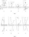
- Figure 1 is the basic representation of the process sequence when penetrating the component 1 on one side with a tool which has a mandrel 2 or is designed as a mandrel 2 which has a longitudinal axis A2, shown in steps A to D.
- the component 1 is a multi-glued wooden panel (laminated wood) with a first side 1.1 and a second side 1.2 and a height h.
- the mandrel 2 has a cylindrical shaft 3 with a diameter D2, to which a tip 4 is connected in the direction of the component 1.
- the tip 4 is essentially conical here and has a cone angle a which is preferably between 15° and 20° (but the angle can also be larger or smaller).
- step A the rotating mandrel 2 is moved with the tip 4 in the direction of the top side 1.1 of the component 1, sits on the side 1.1 here and is now pressed into the component 1 with a force F in the forward stroke, whereby the material of the component 1 is largely radially displaced and partially compacted according to step B.
- step C the mandrel 2 has penetrated the component 1 and a hole L has formed in the component 1 due to the displacement of the material. Local radial compactions V were generated around the hole L over the entire height h of the component 1 due to the displacement of the material of the component 1.
- the mandrel 2 is then removed from the component 1 in a return stroke, preferably rotating according to step D in the direction of the arrow.
- the hole L created in the component 1 has a longitudinal axis A1 and a diameter d, whereby the diameter d corresponds to the diameter D2 of the mandrel 2.
- the local compaction V surrounding the hole L remains in the component 1 after the mandrel 2 is removed, since it is stabilized by the thermoplastically reacting lignin in the forming area of the material.
- mandrel 2 it is also possible for the mandrel 2 to first partially penetrate the component 1, to be retracted again and then to penetrate deeper into the component 1 again, thus performing an alternating forward and backward stroke movement until the mandrel 2 has completely penetrated the component 1.
- Figure 2 shows the principle diagram of the process sequence with steps A to D for two-sided penetration of the component 1 with two mandrels 2 arranged opposite one another, whose longitudinal axes A2 are aligned and which penetrate the component 2 alternately from both sides 1.1, 1.2, always with a feed rate, until the hole L has completely formed in the component 1 (step C).
- step A no rotating mandrel 2 has yet penetrated the component 1.
- step B the upper mandrel 2 has penetrated into the component 1 from the direction of the top side 1.1, but has not yet penetrated it.
- the upper mandrel 2 has retracted from the component 1 according to step C and the lower mandrel 2 has penetrated into the component 1 from the direction of the bottom side 1.2, has completely penetrated it and created the hole L.
- the lower mandrel 2 was then also disengaged according to step D and the process is finished.
- the punch it is also possible for the punch to be surrounded by a hold-down device which, during the forming of the hole, acts on the top or bottom side 1.1, 1.2 of the component 1, depending on the direction from which the mandrel 2 acts.
- a hole L with a diameter d was created in component 1 without pre-drilling.
- the radial compression V of the material, which adjoins the hole L on the circumference, has a diameter dv on the circumference that is up to 5 x d. In the example shown, dv is approximately 2 x d.
- the hole L was created by pre-drilling and then the area of the hole L adjacent to the hole on the circumference was provided with the axial compaction V by an axially acting punch (not shown).
- the height hv of the compacted area V in the area of the hole L is approx. 0.5 x h.
- Figure 5 shows a schematic diagram of the generation of a radial and axial compression V using a mandrel 2, which has a shoulder 5 with a diameter D5, which adjoins the shaft 3, and a counterholder 6.
- the radial compression V was generated with the mandrel 2 and its tip 4, by the mandrel 2 penetrating into the component 1 from the direction of the top side 1.1 and completely penetrating it, so that the hole L with the diameter d was generated.
- the shoulder 5 is pressed axially into the component 1 (see step B), so that in addition to the radial compression, an axial compression V of the material in the component 1 is generated from the direction of the upper side 1.1, whereby the height h of the component 1 in the area of the acting shoulder 5 is reduced to a height hv.
- a counterholder 6 is located on the underside 1.2 of the component 1, which has a bore 6.1 through which the mandrel 2 can engage.
- a screw connection with axial and radial compression V is in Figure 6
- Two components 1 lie against one another with their flat undersides 1.2 and are connected to one another via a screw 7 and a nut 8, with the screw 7 protruding through the aligned holes L of the components 1.
- a washer 9 is provided under the screw head 7.1 and under the nut 8.
- the compacted area V in the two components 1 enables a higher prestress and reduces the settlement phenomena or relaxation and retardation phenomena.
Landscapes
- Engineering & Computer Science (AREA)
- Life Sciences & Earth Sciences (AREA)
- Wood Science & Technology (AREA)
- Mechanical Engineering (AREA)
- Forests & Forestry (AREA)
- Chemical & Material Sciences (AREA)
- Composite Materials (AREA)
- Dry Formation Of Fiberboard And The Like (AREA)
- Moulding By Coating Moulds (AREA)
Description
- Die Erfindung betrifft ein Bauteil aus einem Werkstoff, der überwiegend aus nachwachsenden Rohstoffen besteht, mit mindestens einem verdichteten Bereich sowie ein Verfahren und ein Werkzeug zum Herstellen des verdichteten Bereiches und findet insbesondere für dauerfeste Schraubverbindungen Anwendung.
- Aus dem Stand der Technik ist der Einsatz von Nägeln und Schrauben als Verbindungsmittel sowie Bolzenverbindungen mit der Notwendigkeit des vorherigen Vorbohrens mit Werkzeugen mit geometrisch definierter Schneide bekannt. Bei Nagel und Schraube ist der Ausziehwiderstand zum größten Teil von der Rohdichte des Werkstoffes abhängig. Bei allen Verbindungsarten treten für die Verbindungsfestigkeit meist nachteilige Setzungserscheinungen, hauptsächlich im Holzwerkstoff auf. Für eine dauerfeste Verbindung für ein metallisches Verbindungsmittel ist ein hohes Anzugsmoment notwendig, was eine hohe Flächenpressung unter anderem unter Schraubenkopf/Mutter/Scheibe zur Folge hat. Dadurch wird die Spannung im Holzwerkstoff erhöht und die, für die Verbindungsfestigkeit nachteiligen Relaxations- und Retardationserscheinungen treten auf. Im Stand der Technik wird dieser Effekt durch die Vergrößerung der Auflagefläche, z.B. durch zusätzliche Elemente wie Unterlegscheiben oder durch den Einsatz von Inserts oder Hülsen im Bohrloch abgeschwächt.
- In den Druckschriften
DE 26 32 695 C2 undDE 76 23 015 U1 wird eine Ausgleichsbuchse für die Befestigung von Griffen oder dgl. beschrieben. Dabei sind zwischen Befestigungsgegenstand (z.B. Griff) und Unterlage (z.B. Holzplatte) konische Buchsen angeordnet. Die Unterlage weist eine Durchgangsbohrung im Bereich der Befestigungsstelle auf. Bei der Verschraubung des Griffs mit der Unterlage wird ein Einpressen der Buchsen in diese realisiert. Laut Beschreibung erfolgt dabei eine Verdrängung und somit eine Verdichtung und Verfestigung des Holzes. Weiterhin zentrieren sich die Bauteile zueinander, was zu einer präziseren Positionierung dieser zueinander führt. Durch diese Effekte erfolgt die Realisierung einer Verbindung, die in der Lage ist, hohe Radial-, Axial- und Kippkräfte aufzunehmen. - In
DE 197 24 284 C2 ist eine Koppelpfette aus mehreren überlappend aneinander anschließenden Holzbalken sowie eine Schraube für eine Koppelpfette beschrieben. Bei dieser Erfindung kommen Schrauben zum Einsatz, die sich durch einen abgesetzten Schaft auszeichnen. Beide Bereiche sind mit Gewinde gleicher Steigung, jedoch unterschiedlichen Durchmessers, versehen. Die Gewinde haben dabei keine vorrangige schneidende, sondern eine verdrängende Funktion. Durch die abgestufte Gestaltung des Schraubenschafts erfolgt eine zweistufige Verfestigung des Werkstoffs und somit eine zusätzliche Erhöhung der Belastbarkeit der Verbindung. Ein weiterer positiver Effekt wird dadurch erzielt, dass der Schraubenkopf als relativ schlanker Kegel ausgebildet ist. Diese Gestaltung bewirkt, dass dieser leicht versenkbar ist, ohne dass ein zusätzlicher Arbeitsgang durch die Ausformung einer Senkung notwendig ist. Durch den Schraubenkopfkegel kommt es zu einer weiteren Werkstoffverfestigung. Im Schutzrecht wird ausgeführt, dass das Verbauen der Schrauben ohne Vorbohren möglich ist, ohne dass die Gefahr besteht, dass das Holz an seinen Enden aufreißt. - In
DE 10 2016 120 728 A1 ist eine keglige Schraube für geschäumte Kunststoffe beschrieben. Hierbei handelt es sich um eine Verbindung in einem Kunststoff, mit einer definierten Elastizität. Das Schraubengewinde ist keglig ausgebildet. Es kommt beim Eindrehen des Gewindes nicht zur Zerstörung des Materials, sondern zu dessen Verdrängung und Komprimierung. Je tiefer das Gewinde eingeschraubt wird, desto größer wird der Durchmesser des Kegels und desto mehr Material wird verdrängt. Dies führt dazu, dass das Rückstellmoment, welches zum Eindrehen notwendig ist, ansteigt und somit auch die Anpresskraft, die sich zwischen den zu verbindenden Teilen ausbildet, ansteigt. Dadurch entsteht eine große Flächenpressung zwischen diesen, was zu einer belastbaren Verbindung führt. - In
WO 2016 162 111 A1 ist eine reversible Verbindung zwischen Maschinenteilen beschrieben. Dabei wird ein fließfähiges Medium in einen Hohlraum eines Bauteils eingebracht und dieser wird verschlossen. Im Ausführungsbeispiel handelt es sich um eine Welle. In das fließfähige Medium erfolgt das Eindrehen eines kegligen Körpers, der dieses verdrängt. Somit bildet sich ein Druck im Hohlraum aus, der dazu führt, dass sich dieser erweitert, wodurch beispielsweise eine Welle-Nabe-Verbindung realisiert werden kann. Weiterer Stand der Technik ist bekannt ausUS 4 248 820 A undDE 20 2009 007835 U . - Einige oben genannte Patentschriften hinsichtlich einer Verdichtung beziehen sich im Allgemeinen darauf, dass die Verdichtung der lokalen Stelle durch das Verbindungsmittel während des Anziehens des Verbindungsmittels verursacht wird. Die Verdichtungsgüte ist dadurch nur so groß, wie die maximale Vorspannkraft des Verbindungsmittels in Abhängigkeit der Schraubenkopffläche in Kombination der Druckfestigkeit des zu verdichtenden Werkstoffes möglich ist. Die maximal mögliche Verdichtung auf 1,4g/cm3 bei dessen Dichte der Werkstoff seine maximal möglichen mechanischen Eigenschaften aufweist ist im Regelfall nicht mit stiftförmigen Verbindungsmitteln und dessen resultierender Schraubenkopffläche realisierbar. Die Zugfestigkeit der Schraube ist bereits deutlich vor dem Erlangen der maximal möglichen Druckfestigkeit des Werkstoffes erschöpft. Retardations- bzw. Relaxationserscheinungen sind jedoch erst bei dieser Grenze nennenswert reduziert.
- Bei der herkömmlichen Herstellung von Bohrungen in plattenförmigen Halbzeugen aus Holzwerkstoffen erfährt der Werkstoff eine spanende geometrische Formänderung. Nachteilig ist, dass die mechanischen Werkstoffeigenschaften im Bohrlochrandbereich des Werkstoffes gerade bezüglich der Dichteeigenschaften, sowie der Druckfestigkeit nicht bzw. so gering verändert werden, dass keine signifikante Relevanz besteht. Aufgabe der Erfindung ist es, ein Bauteil aus einem Werkstoff, der überwiegend aus nachwachsenden Rohstoffen besteht und mindestens einen verdichteten Bereich aufweist sowie ein Verfahren und Werkzeug zum Herstellen des verdichteten Bereiches zu entwickeln, welches eine lokale Erhöhung der Werkstoffdichte und damit der mechanischen Eigenschaften ohne die Notwendigkeit der Einbringung eines zusätzlichen Verbindungsmittels wie zum Beispiel von Inserts oder Hülsen mit höherer Dichte oder Festigkeit als der ursprüngliche Holzwerkstoff ermöglicht.
- Diese Aufgabe wird mit den Merkmalen des ersten, dritten und neunten Patentanspruchs gelöst. Vorteilhafte Ausgestaltungen ergeben sich aus den Unteransprüchen.
- Das Bauteil besteht dabei aus einem Werkstoff, der überwiegend aus nachwachsenden Rohstoffen gebildet wird, wobei das das Bauteil wenigstens ein Loch mit einer Längsachse aufweist und erfindungsgemäß der Werkstoff des Bauteils in dem sich an das Loch umfangsseitig anschließenden Bereich eine lokale Verdichtung aufweist. Durch die lokale Verdichtung werden Setzerscheinungen, die bei Herstellen einer Schraubverbindung mit einem anderen Bauteil auftreten, reduziert.
- Der sich an das Loch umfangsseitig anschließende Bereich des Bauteils weist radiale und/oder axiale lokale Verdichtungen auf.
- Das Bauteil kann bei der axialen Verdichtung im Vorfeld radial verdichtet sein. Somit ergäbe sich eine kombinierte Verdichtung von 1. Radial und 2. Axial. Somit wäre die Lochaussparung im Vorfeld zur axialen Verdichtung eingebracht.
- Die 2. Variante wäre eine axiale Verdichtung und im Nachgang dazu eine Bohrung (spanend) umzusetzen.
- Damit wäre die Verdichtung keine Kombination, sondern lediglich eine Einstufige Verdichtung mit der anschließenden Schraubenaussparung im spanenden Prozess zu unterziehen.
- Wenn das Loch einen Durchmesser aufweist, beträgt der sich an das Loch umfangsseitig anschließende Umfang des verdichteten Bereiches bis zum fünffachen des Durchmessers des Lochs.
- Die Höhe des verdichteten Bereiches beträgt bis zum zwanzigfachen des Lochdurchmessers und ist vorzugsweise im Vergleich zur Höhe des Bauteils des reduziert.
- Das im Bauteil vorhandene Loch ist ein zylindrisches oder nahezu zylindrisches Loch und als Durchgangsloch in dem Bauteil ausgebildet ist oder weist einen Boden auf.
- Der Werkstoff des Bauteils besteht aus Holz oder weist mindestens 50% Anteil an nachwachsenden Rohstoffen auf.
- Besonders bevorzugt ist der der Werkstoff ein Holzwerkstoff, dem bedarfsweise weniger als 50% Anteile an anderen nachwachsenden Rohstoffen wie Graswerkstoffe (Bambus), beigefügt sind,
- Das Bauteil kann auch ein Hybridwerkstoff wie Wood Plastic Composite (WPC) mit nachwachsenden Rohstoffen sein.
- Weiterhin kann das Bauteil eine oder mehrere Materialschichten aus Metall, Kunststoff, Faserverbundmaterial, Papier oder Pappe oder einer Kombination dieser Materialschichten aufweisen.
- Das Bauteil ist bevorzugt in Form einer Platte ausgebildet und weist mindestens zwei Lagen mit nachwachsenden Rohstoffen, bevorzugt drei Holzlagen auf, die bedarfsweise mit weiteren Materialschichten kombiniert sein können.
- Das Loch wird bevorzugt in einem Winkel von 90° bis 45° zur Oberseite des Bauteils in das Bauteil eingebracht.
- Das Verfahren zum Herstellen mindestens eines verdichteten Bereiches in einem Bauteil aus einem Werkstoff, der zu mindestens 50% aus nachwachsenden Rohstoffen besteht, erfolgt dadurch, dass mindestens ein rotierender Dorn in den Werkstoff des Bauteils eindringt und dadurch ein Loch im Bauteil erzeugt und den Werkstoff radial und/oder axial verdrängt und dabei in dem das Loch umgebenden Bereich des Werkstoffs eine lokale Verdichtung (V) erzeugt.
- Alternativ erfolgt das Verfahren zum Herstellen mindestens eines verdichteten Bereiches in einem Bauteil aus einem Werkstoff, der zu mindestens 50% aus nachwachsenden Rohstoffen besteht, dadurch, dass mindestens ein rotierender Dorn in den Werkstoff des Bauteils eindringt und dadurch eine Vertiefung im Bauteil erzeugt und den Werkstoff radial und/oder axial verdrängt und dabei in dem Werkstoff eine lokale Verdichtung (V) erzeugt.
- Gemäß einer Ausgestaltung der Erfindung können zwei sich gegenüberliegende Dorne Anwendung finden, die wechselseitig aus sich gegenüberliegenden Richtungen in das Bauteil eindringen und das Loch mit dem Durchmesser erzeugen und dabei den Werkstoff verdrängen und in dem das Loch umgebenden Bereich verdichten.
- Alternativ können zwei sich gegenüberliegende Dorne Anwendung finden und aus sich gegenüberliegenden Richtungen eine Vertiefung im Bauteil erzeugen und den zwischen den Dornen befindlichen Bereich des Bauteils verdichten. Der wenigstens eine Dorn oder die sich gegenüberliegenden Dorne rotieren zumindest während des Eindringens in das Bauteil.
- Es kann nach dem teilweisen Eindringen eines Dorns in das Bauteil eine Rückhubbewegung des in Eingriff befindlichen Dorns erfolgen und danach eine erneute Vorhubbewegung des Dorns, bei welcher der Dorn weiter in das Bauteil eindringt, bis der Dorn das Bauteil vollständig durchdrungen hat.
- Finden zwei sich gegenüberliegende Dorne Anwendung, kann bei einer Rückhubbewegung eines Dorns eine Vorhubbewegung des gegenüberliegenden Dorns in das Bauteil erfolgen. Dies wird solange im Wechsel durchgeführt, bis das durchgehende Loch im Bauteil erzeugt ist.
- Eine maximale Eindringtiefe des Dorns je Vorwärtshub wird dabei bevorzugt in Abhängigkeit vom Bauteil (Material und Dichte des Bauteils) sowie von einer Drehzahl des Dorns und/oder einer Vorschubgeschwindigkeit des Dorns festgelegt.
- Nach Erreichen dieser festgelegten maximalen Eindringtiefe je Vorschubbewegung vollführt der Dorn einen Rückhub. Dadurch wird vermieden, dass das Bauteil durch die entstehende Reibung zu stark erwärmt wird.
- Die entsprechenden Werte können einfach durch Referenzversuche ermittelt werden. Bevorzugt werden somit Drehzahl und/oder die Vorschubgeschwindigkeit und/oder die maximale Eindringtiefe empirisch ermittelt.
- Dabei wird die maximale Eindringtiefe des jeweiligen Stempels je Hub so festgelegt, dass eine auf das Bauteil durch die Reibung des Stempels wirkende Temperatur maximal 200°C beträgt. (Eventuell auch mehr oder weniger, je nach Bauweilwerkstoff).
- Das Werkzeug zur Durchführung des Verfahrens dient zur Erzeugung einer überwiegend radialen Verdichtung und ist in Form wenigstens eines Dorns mit einem zylindrischen oder polygonförmigem Schaft und einer sich in Richtung zum Bauteil im Durchmesser reduzierenden Spitze ausgebildet.
- Dabei weist das Werkzeug zur Erzeugung einer überwiegend axialen Verdichtung in Richtung zum Bauteil eine platte / plane / konisch mit stumpfen Winkel Fläche auf und/oder erweitert sich vom Bauteil weg im Durchmesser.
- Der Winkel des stumpf ausgeführten (temperaturbeaufschlagten o. kalten) Formwerkzeuges hat mindestens den Winkel des durch die Verdichtung des Bauteils maximal möglicher Dehnung der in dem Fall vor der Verdichtung ensprechenden Ankathete welcher nach der Verdichtung zur im Dreieck aufgespannten Hypotenuse wird. Diese Dehnung muss mindestens 1% betragen und somit ergibt sich der entsprechenden Winkel des Formwerkzeuges in Abhängigkeit der Dehnung.
- Die Spitze des Dorns kann auch in Form einer Kegelspitze, eines Kegelstumpfes oder in einer anderen sich in Richtung zum Bauteil im Durchmesser reduzierenden Form ausgebildet sein.
- An der dem Dorn gegenüberliegenden Seite des Bauteils kann ein Gegenhalter angeordnet sein und/oder der Dorn kann auch von einem Niederhalter umringt sein. Der Dorn ists mittels eines ersten Antriebes in Rotation versetzbar und mittels eines zweiten Antriebes in Richtung zur Längsachse des Dorns bewegbar wenn eine radiale Verdichtung erzeugt und ein Loch hergestellt werden soll.
- Alternativ ist der Dorn nur mittels eines zweiten Antriebes in Richtung zur Längsachse des Dorns bewegbar ist, wenn nur eine axiale Verdichtung erzeugt werden soll.
- Gemäß einer Variante der Erfindung kann der Dorn beheizt sein.
- Bei einem unbeheizten rotierenden Stempel können auch durch Reibung hohe Temperaturen erreicht werden.
- Das Werkzeug kann dabei einen Temperatursensor aufweisen.
- Der axial bzw. radial wirkende Stempel kann auch unbeheizt (kalt) sein, wobei mit dem rotierenden Stempel durch die Reibung mit dem Bauteil auch passiv hohe Temperaturen erreicht werden.
- Bei der Ausformung der axialen Verdichtung kann nach Erreichen der gewünschten Endform das Formwerkzeug (der Dorn) abgekühlt werden (wenn dieser beheizt ist) oder im heißen Zustand ausgeformt werden. Dabei kann die Abkühlung aktiv oder passiv erzeugt werden.
- Die Erfindung betrifft die Ausbildung einer dauerhaft gleitfest vorgespannten Verbindungsstelle in einem Werkstoff der zumindest 50% aus nachwachsenden Rohstoffen besteht, mit metallischen Verbindungsmitteln, indem die Unterschiede in den mechanischen Eigenschaften zwischen dem Werkstoff und den metallischen Verbindungsmittel minimiert werden.
- Der starke Abfall der Vorspannkraft von gleitfest vorgespannten metallischen Verbindungsmitteln, wie Schrauben durch auftretende Relaxations- und Retardationserscheinungen im Werkstoff eines Bauteils, wird erfindungsgemäß durch eine lokal definierte Erhöhung der Werkstoffrohdichte realisiert. Diese lokale Dichteerhöhung kann durch die erfindungsgemäße Lösung in Form der axialen und/oder radialen Verdichtung während der Halbzeugherstellung oder nachträglich durch entsprechende erfindungsgemäße Werkzeuge erzielt werden.
- Verbindungsmittel zur Direktverschraubung z. B. selbstschneidende, gewindeformende Schrauben sind davon ausgenommen, weil diese keine dauerhafte gleitfest vorgespannte Verbindung ermöglichen.
- Die Verbindungstelle wird gemäß des erfindungsgemäßen Verfahrens dabei über den kompletten Verbindungsquerschnitt so hoch verdichtet, dass eine dauerhafte gleitfest vorgespannte Schraubverbindung, ohne zusätzliches Verbindungsmittel und Nachspannen dessen realisiert wird. Diese Art Werkstoffverdichtung ist mit Verbindungsmittel bekannter Art im ein- oder zweistufigen Verfahren nicht möglich, weil die zulässige Vorspannkraft des Verbindungmittels dafür zu niedrig ist. Die Verformung des Werkstoffs, insbesondere des Holzwerkstoffes oder einem anderen nachwachsenden Rohstoff (z.B. Bambus oder einer Mischung verschiedener nachwachsender Rohstoffe) in der Verbindungstelle ist plastisch, sie wird im Herstellungsprozess mit pflanzeneigenen Bestandteilen Cellulose, Hemicellulose und Lignin über physikalisch-chemische Prozesse fixiert.
- Lignine bilden eine Gruppe von phenolischen Makromolekülen, die sich aus verschiedenen Monomerbausteinen zusammensetzen. Es sind feste Biopolymere, die in die pflanzliche Zellwand eingelagert werden und dadurch die Verholzung der Zelle bewirken (Lignifizierung). Diese Einlagerungen findet man in den Zellwänden von verholzten Pflanzen wie Bambuspflanzen, Gräsern, Stauden, Sträuchern und Bäumen. Lignin hat als Stützmaterial und verhärtetes Polymer eine Reihe wichtiger Aufgaben für die Pflanze. Lignine sind wesentlich für die Festigkeit pflanzlicher Gewebe, vor allem für ihre Druckfestigkeit, während die eingelagerten Cellulosefasern die Zugfestigkeit gewährleisten. Reißfeste, biegsame Fasern (Cellulose) werden also von einem dichten und starren Polymer als Füllmaterial (Lignin) durchdrungen.
- Erstmalig wird das im Bauteil enthaltene Lignin zur Erzeugung der lokalen Verdichtungsstellen im Bauteil genutzt, welche durch die Umformung des Bauteils im Bereich der erzeugten Löcher erzeugt werden. Durch das Lignin werden die Verdichtungsstellen stabilisiert, denn es reagiert ähnlich einem Thermoplast.
- Durch die bei der Herstellung der Löcher mit dem Werkzeug auftretende Reibung wird der Werkstoff erwärmt, wodurch das Lignin plastifiziert wird und beim Abkühlen wieder aushärtet und dadurch dem umgeformten Bereich wieder stabilisiert.
- Bei bzw. nach der Formgebung der Verbindungsstelle verbleibt weder das Formwerkzeug noch das Verbindungsmittel zur Ausformung der Verbindungstelle nach Abschluss des Formgebungsprozesses in Verwendung. Nachfolgend wir die hochbelastbare Verbindungsstelle inkl. Standardverbindungsmitteln (Maschinenbauschraube, Scheiben, Mutter) genutzt, um die dauerhafte gleitfest vorgespannte Verbindung umzusetzen.
- Das erfindungsgemäße Bauteil weist zumindest eine lokale axial und /oder radiale erzeugte Verdichtungsstelle mit einem definiertem Lochdurchmesser auf, wodurch die an dem Bauteil erzeugte Schraubverbindung höheren Belastungen standhält und Setzerscheinungen und innerer Spannungsabbau im Bereich der Schraubverbindung aufgrund der lokalen Verdichtungsstellen im Vergleich zu herkömmlichen Verbindungen, bei welchen die Bauteile keine Verdichtungsstellen aufweisen, reduziert werden. Verfahrensgemäß werden die lokalen Verfestigungen in dem Bauteil mittels eines entsprechenden Werkzeuges, welches am Bauteil aus einer Richtung oder aus zwei sich gegenüberliegenden Richtungen angreift durchgeführt. Dies erfolgt mit mindestens einem rotierenden Dorn, welcher eine definierte werkstoffabhängige Kraft auf das Werkstück bewirkt. Dies erfolgt durch den Vorschub des Dorns in Abhängigkeit der Rotationsgeschwindigkeit und der an der Wirkstelle auftretenden Temperatur.
- Als Werkstoffe finden insbesondere nachwachsende Rohstoffe Anwendung, wobei der Anteil an nachwachsenden Rohstoffen mindestens 50% betragen sollte. Bevorzugt finden Holzwerkstoffe Anwendung oder auch Holzwerkstoffe in Kombination mit einem Anteil an nachwachsenden Rohstoffen <50%.
- Insbesondere besteht der Werkstoff der Bauteile aus vorwiegend nachwachsenden Rohstoffen wie Holzwerkstoffe, Graswerkstoffe (Bambus) oder aus hybridem Material wie Wood Plastic Composite (WPC) oder Holzwerkstoffe mit metallischen Lagen, Kunststofflagen, Papier- oder Papplagen als Deck- und/oder Zwischenschichten bzw. einer beliebigen Kombination der vorgenannten Materialien.
- Werden Werkstoffe aus Holz eingesetzt, sind dies insbesondere Bauteile mit einem geschichteten Aufbau mit mindestens drei untereinander verbundenen Schichten. Derartige Bauteile werden als Lagenholz bezeichnet.
- Bevorzugt besteht das Bauteil aus Lagenholz, insbesondere aus Sperrholz. Sperrholz ist die spezifiziertere Legeart der Furniere, wo sich die richtungsabhängigen Eigenschaften durch eine insbesondere 0°-90° Faserverlauforientierung in eine Sperrwirkung verstärken. Es sind jedoch auch andere Sperrhölzer mit Orientierungen welche vom 0°-90° abweichen, verwendbar.
- Es können jedoch auch Bauteile aus Bambus oder mit Bambusanteil Anwendung finden, beziehungsweise generell nachwachsende Rohstoffe, die Lignin enthalten.
- Die Bauteile sind insbesondere plattenförmig ausgebildet, können aber auch in anderer geometrischer Form vorliegen.
- In Bezug auf die Oberfläche des Bauteils kann vorzugsweise ein Angriffswinkel des Werkstücks von 90° Anwendung finden, jedoch auch ein davon abweichender Winkel der Bearbeitungsrichtung, wie beispielsweise bis 45°.
- Durch das Werkzeug wird ein nahezu zylindrisches Loch erzeugt, welches als Durchgangsloch ausgebildet ist oder auch einen Boden aufweisen kann. Der Bereich der lokalen Verfestigung in Abhängigkeit von dem erzeugten Durchmesser D des Lochs beträgt bevorzugt bei einer radialen Verdichtung bis zu des fünffachen des Durchmessers und bei einer axialen Verdichtung bis zu zwanzigfachen des Durchmessers.
- D ist dabei der Formgebende Werkzeugdurchmesser. Der Bereich der Verdichtung ist größer und abhängig von D (ein Vielfache=20x), des lokalen Einflussbereiches eines erzeugten zylindrischen Loches. Die Prozesse spielen sich alle in dem definierten lokalen Bereich von bis zu zwanzigfachen des Durchmessers um das mit dem Stempel erzeugte Loch ab.
- Es ist möglich, das Loch mit der dieses umgebenden Verdichtungsstelle ohne Vorbohren oder auch mit Vorbohren zu erzeugen.
- Bei einem Verhältnis Durchmesser-Plattenstärke (bei einem plattenförmigen Bauteil) als Bereich ohne Vorbohren ist das Verhältnis bis 1:2 (Bsp.: 10mm Werkzeugdurchmesser, 20mm Plattenstärke). Bei einem Verhältnis ab 1:4 bis 10:1 Durchmesser D des zu erzeugenden Lochs zu Plattenstärke sollte ein durchmesserabhängiges Vorbohren erfolgen.
- Der vorzubohrende Durchmesser sollte 0,1 bis 0,9 x D sein.
- Der Temperaturbereich an der Stelle, an der das Werkstück wirkt, d.h. an der Wirkstelle sollte zwischen 0°C - 210°C, bevorzugt 100°C-150°C, besonders bevorzugt bei 140°C liegen. Insbesondere bei Temperaturen über 100°C wird das im Werkstoff enthaltene Lignin in Verbindung mit dem im Werkstoff wirkenden Umformdruck plastifiziert und verfestigt sich beim Abkühlen wieder.
- Es ist möglich das Einbringen der Löcher mit oder ohne Gegenhalter zu realisieren. Ein Gegenhalter ist beispielsweise möglich bei einseitigem und zweiseitigen radialem Verdichtungsprozess, bei einseitigem oder zweiseitigem Eindrücken der Löcher und/oder kombinierter Verdichtung - axial und/oder radial.
- Vorzugsweise wird das Verfahren ohne Niederhalter durchgeführt.
- Es kann jedoch auf der Seite des Werkzeugs auch ein Niederhalter vorgesehen werden, der das Werkzeug umringt und auf die Oberfläche des Bauteils mit einer Niederhalterkraft wirkt.
- Dies kann bei einem einseitigen Verdichtungsprozess der Fall sein, d.h. wenn nur ein Werkzeug zur Herstellung des Lochs Anwendung findet oder auch bei einem zweiseitigen radialen Verdichtungsprozess, d.h. wenn zwei sich gegenüberliegende Werkzeuge auf das Bauteil wirken, auf jeder Seite des plattenförmigen Bauteils ein Dorn.
- Somit kann der Niederhalter beim Einseitigen/zweiseitigem Drücken und/oder kombinierter Verdichtung Anwendung finden.
- Mit der erfindungsgemäßen Lösung werden bei Einbringen der für eine Schraubverbindung erforderlichen Löcher lokale Verfestigungen in dem Bauteil erzeugt, die eine höhere Belastbarkeit der Schraubverbindung gewährleisten.
- Die Erfindung wird nachfolgend an einem Ausführungsbeispiel und zugehörigen Zeichnungen näher erläutert.
- Es zeigen:
- Figur 1
- die Prinzipdarstellung des Verfahrensablaufes beim einseitigen Durchdringen des Bauteils mit einem Dorn,
- Figur 2
- die Prinzipdarstellung des Verfahrensablaufes beim zweiseitigen Durchdringen des Bauteils mit zwei sich gegenüberliegend angeordneten Dornen,
- Figur 3
- die Prinzipdarstellung eines Bauteils mit einer erfindungsgemäßen radialen Verdichtung,
- Figur 4
- die Prinzipdarstellung einer erfindungsgemäßen axialen Verdichtung über den kompletten Verbindungsquerschnitt des Bauteils,
- Figur 5
- die Prinzipdarstellung der Erzeugung einer radialen und axialen Verdichtung unter Verwendung eines Gegenhalters,
- Figur 6
- die Verschraubung von zwei Bauteilen 1 mit axialer und radialer Verdichtung.
- In
Figur 1 ist die Prinzipdarstellung des Verfahrensablaufes beim einseitigen Durchdringen des Bauteils 1 mit einem Werkzeug, welches einen Dorn 2 aufweist bzw. als Dorn 2 ausgebildet ist, der eine Längsachse A2 aufweist, in den Schritten A bis D dargestellt. Das Bauteil 1 ist eine mehrfach geleimte Holzplatte (Lagenholz) mit einer ersten Seite 1.1 und einer zweiten Seite 1.2 und einer Höhe h. Der Dorn 2 weist einen zylindrischen Schaft 3 mit einem Durchmesser D2 auf, an welchen sich in Richtung zum Bauteil 1 eine Spitze 4 anschließt. Die Spitze 4 ist hier im Wesentlichen kegelförmig ausgebildet und weist einen Kegelwinkel a auf, der bevorzugt zwischen 15° und 20° liegt (der Winkel kann aber auch größer oder kleiner sein). - Bei dem Schritt A wird der rotierende Dorn 2 mit der Spitze 4 in Richtung zur Oberseite 1.1 des Bauteils 1 bewegt, sitzt hier auf der Seite 1.1 auf und wird nun im Vorhub mit einer Kraft F in das Bauteil 1 gedrückt, wobei gemäß Schritt B der Werkstoff des Bauteils 1 größtenteils radial verdrängt und partiell verdichtet wird. In Schritt C hat der Dorn 2 das Bauteil 1 durchdrungen und es hat sich ein Loch L im Bauteil 1 durch die Verdrängung des Werkstoffs ausgebildet. Um das Loch L wurden durch die Verdrängung des Werkstoffs des Bauteils 1 lokale radiale Verdichtungen V über die gesamte Höhe h des Bauteils 1 erzeugt. Anschließend wird der Dorn 2 in einem Rückhub vorzugsweise rotierend gemäß Schritt D in Pfeilrichtung aus dem Bauteil 1 entfernt. Das im Bauteil 1 erzeugte Loch L weist eine Längsachse A1 und einen Durchmesser d auf, wobei der Durchmesser d dem Durchmesser D2 des Dorns 2 entspricht. Die das Loch L umgebende lokale Verdichtung V bleibt nach dem Entfernen des Dorns 2 im Bauteil 1 bestehen, da diese durch das thermoplastisch reagierende Lignin im Umformbereich des Werkstoffs stabilisiert ist.
- Es besteht auch die Möglichkeit, dass der Dorn 2 erst teilweise in das Bauteil 1 eindringt, wieder zurückgefahren wird und dann erneut tiefer in das Bauteil 1 eindringt und somit eine alternierende Vor- und Rückhubbewegung vollführt, bis der Dorn 2 das Bauteil 1 vollständig durchdrungen hat.
-
Figur 2 zeigt die Prinzipdarstellung des Verfahrensablaufes mit den Schritten A bis D beim zweiseitigen Durchdringen des Bauteils 1 mit zwei sich gegenüberliegend angeordneten Dornen 2, deren Längsachsen A2 fluchten und die abwechselnd von beiden Seiten 1.1, 1.2 immer mit einem Vorschub in das Bauteil 2 eindringen, bis das Loch L sich vollständig im Bauteil 1 ausgebildet hat (Schritt C). Gemäß Schritt A ist noch kein rotierender Dorn 2 in das Bauteil 1 eingedrungen. In Schritt B ist der hier obere Dorn 2 aus Richtung der Oberseite 1.1 des Bauteils 1 in dieses eingedrungen, hat es aber noch nicht durchdrungen. Der obere Dorn 2 ist gemäß Schritt C aus dem Bauteil 1 zurückgefahren und der untere Dorn 2 ist aus Richtung der Unterseite 1.2 des Bauteils 1 in dieses eingedrungen und hat dieses komplett durchdrungen und das Loch L erzeugt. Darauf wurde der untere Dorn 2 gemäß Schritt D ebenfalls außer Eingriff gebracht und das Verfahren ist beendet. - Bei den vorgenannten Beispielen wird der Dorn 2 im Wesentlichen rechtwinklig = Winkel 90° zur Oberseite 1.1 bzw. zur Unterseite 1.2 des Bauteils 1 eingebracht. Es besteht auch die Möglichkeit, den Dorn 2 in einem anderen Neigungswinkel in das Bauteil 1 einzuformen und dadurch ein Loch L zu erzeugen, dessen Längsachse A1 im Bauteilschräg verläuft.
- Es besteht weiterhin die Möglichkeit, dass der Stempel von einem Niederhalter umringt ist, der während des Einformens des Loches auf die Ober oder Unterseite 1.1, 1.2 des Bauteils 1, je nachdem, aus welcher Richtung der Dorn 2 angreift, wirkt.
- Die Prinzipdarstellung eines Bauteils 1 mit einer erfindungsgemäßen radialen Verdichtung V ist in
Figur 3 dargestellt. - Es wurde hier im Bauteil 1 ohne Vorbohren ein Loch L mit einem Durchmesser d erzeugt. Die hier radiale Verdichtung V des Werkstoffs, welche sich an das Loch L umfangsseitig anschließt, weist umfangsseitig einen Durchmesser dv auf, der bis 5 x d beträgt. Im dargestellten Beispiel beträgt dv ca. 2 x d.
- Gemäß
Figur 4 ist es auch möglich, nur eine axiale Verdichtung V zu erzeugen, die über den kompletten Verbindungsquerschnitt des Bauteils 1 reicht. - Dabei wurde das Loch L durch Vorbohren hergestellt und anschließend der sich umfangsseitig an das Loch anschließende Bereich des Loches L durch einen nicht dargestellten axial wirkenden Stempel mit der axialen Verdichtung V versehen. Die Höhe hv des verdichteten Bereiches V im Bereich des Loches L beträgt hier ca. 0,5 x h.
-
Figur 5 zeigt eine Prinzipdarstellung der Erzeugung einer radialen und axialen Verdichtung V unter Verwendung eines Dorns 2, der eine Schulter 5 mit einem Durchmesser D5 aufweist, die sich an den Schaft 3 anschließt und eines Gegenhalters 6. Es wurde zuerst in Schritt A die radiale Verdichtung V mit dem Dorn 2 und dessen Spitze 4 erzeugt, indem der Dorn 2 aus Richtung der Oberseite 1.1 in das Bauteil 1 eindringt und dieses vollständig durchdrungen hat, so dass das Loch L mit dem Durchmesser d erzeugt wurde. - Bei einem weiteren Vorschub wird die Schulter 5 in das Bauteil 1 axial eingepresst (siehe Schritt B), so dass im Bauteil 1 zusätzlich zur radialen Verdichtung eine axiale Verdichtung V des Werkstoffs im Bauteil 1 aus Richtung der Oberseite 1.1 erzeugt wird, wobei sich die Höhe h des Bauteils 1 in dem Bereich der wirkenden Schulter 5 auf eine Höhe hv verringert.
- An der Unterseite 1.2 des Bauteils 1 liegt bei beiden Stufen ein Gegenhalter 6 an, der eine Bohrung 6.1 aufweist, durch welche der Dorn 2 greifen kann.
- Eine Verschraubung mit axialer und radialer Verdichtung V ist in
Figur 6 dargestellt. Zwei Bauteile 1 liegen mit ihren ebenen Unterseiten 1.2 aneinander an und sind über eine Schraube 7 und eine Mutter 8 miteinander verbunden, wobei die Schraube 7 durch die zueinander fluchtenden Löcher L der Bauteile 1 ragt. Unter dem Schraubenkopf 7.1 und unter der Mutter 8 ist jeweils eine Unterlegscheibe 9 vorgesehen. - Der verdichtete Bereich V in den beiden Bauteilen 1 ermöglicht eine höhere Vorspannung und reduziert die Setzerscheinungen bzw. Relaxation und Retadationserscheinungen.
-
- 1
- Bauteil
- 1.1
- Oberseite
- 1.2
- Unterseite
- 2
- Dorn
- 3
- Schaft
- 4
- Spitze
- 5
- Schulter
- 6
- Gegenhalter
- 7
- Schraube
- 7.1
- Schraubenkopf
- 8
- Mutter
- 9
- Unterlegscheibe
- a
- Kegelwinkel der Spitze
- b
- Eindringwinkel des Dorns
- d
- Durchmesser des Lochs L
- dv
- Umfang des verdichteten Bereiches
- h
- Höhe des Bauteils 1
- hv
- Höhe des verdichteten Bereiches
- A
- Längsachse
- D2
- Durchmesser des Dorns, der sich an die Spitze 4 anschließt
- D5
- Durchmesser der Schulter 5
- F
- Kraft
- L
- Loch
- V
- Verdichtung
Claims (11)
- Bauteil aus einem Werkstoff, der überwiegend aus nachwachsenden Rohstoffen besteht,- wobei das Bauteil (1)• aus Lagenholz besteht
oder• in Form einer Platte ausgebildet ist und mindestens drei Lagen mit nachwachsenden Rohstoffen aufweist, die mit weiteren Materialschichten kombiniert sind, wobei das Bauteil eine oder mehrere Materialschichten aus Metall, Kunststoff, Faserverbundmaterial, Papier oder Pappe oder einer Kombination dieser Materialschichten aufweistund- wobei das Bauteil wenigstens ein, zur Herstellung einer Verbindung mittels einer Verschraubung mit einem weiteren Bauteil dienendes, Loch (L) mit einer Längsachse (A1) aufweist um eine Verbindung mittels einer Verschraubung herzustellen
und- wobei der Werkstoff des Bauteils (1) in dem sich an das Loch (L) umfangsseitig anschließenden Bereich eine durch das Eindringen eines rotierenden Dorns erzeugte, eine dauerhaft gleitfest vorgespannte Verbindungsstelle für die Verschraubung realisierende, lokale Verdichtung (V) aufweist, wobei das Loch (L) ein zylindrisches oder nahezu zylindrisches Loch ist (L) und als Durchgangsloch in dem Bauteil (1) ausgebildet ist oder einen Boden aufweist und wobei der sich an das Loch (L) umfangsseitig anschließende Bereich des Bauteils (1) radiale und/oder axiale lokale Verdichtungen (V) aufweist und wobei das Loch (L) einen Durchmesser (d) aufweist und- der sich an das Loch (L) umfangsseitig anschließende Umfang (dv) des verdichteten Bereiches bis zum fünffachen des Durchmessers (d) beträgt und/oder dass die Höhe (hv) des verdichteten Bereiches bis zum zwanzigfachen des Durchmessers (d) beträgt und/oder im Vergleich zur Höhe (h) des Bauteils (1) reduziert ist. - Bauteil nach Anspruch 1, dadurch gekennzeichnet, dass das Loch (L) in einem Winkel (b) von 90° bis 45° zur Oberseite (1.1) des Bauteils (1) in das Bauteil (1) eingebracht ist.
- Verfahren zum Herstellen eines Bauteils nach Anspruch 1, dadurch gekennzeichnet, dass mindestens ein Dorn (2) mit einem zylindrischen Schaft (3) und einer sich in Richtung zum Bauteil (1) im Durchmesser reduzierenden Spitze (4) in den Werkstoff des Bauteils (1) eindringt und dadurch ein Loch (L) im Bauteil (1) erzeugt und den Werkstoff radial und/oder axial verdrängt und dabei in dem das Loch (L) umgebenden Bereich des Werkstoffs eine lokale Verdichtung (V) erzeugt, wobei der Dorn (2) zumindest während des Eindringens in das Bauteil (1) rotiert.
- Verfahren nach Anspruch 3, dadurch gekennzeichnet, dass zwei sich gegenüberliegende Dorne (2) Anwendung finden, die wechselseitig aus sich gegenüberliegenden Richtungen in das Bauteil (1) eindringen und das Loch (L) mit dem Durchmesser (d) erzeugen und dabei den Werkstoff verdrängen und in dem das Loch (L) umgebenden Bereich verdichten, wobei beide Dorne (2) zumindest während des Eindringens in das Bauteil (1) rotieren.
- Verfahren nach Anspruch 3 oder 4, dadurch gekennzeichnet, dass eine Rückhubbewegung des in Eingriff befindlichen Dorns (2) erfolgt und danach eine erneute Vorhubbewegung des Dorns (2), bei welcher der Dorn (2) weiter in das Bauteil (1) eindringt und/oder dass bei einer Rückhubbewegung eines Dorns (2) eine Vorhubbewegung eines gegenüberliegenden Dorns (2) in das Bauteil (1) erfolgt.
- Verfahren nach einem der Ansprüche 3 bis 5, dadurch gekennzeichnet, dass eine maximale Eindringtiefe des Dorns (2) in Abhängigkeit- vom Bauteil (1) sowie- von einer Drehzahl des Dorns (2) und/oder- einer Vorschubgeschwindigkeit des Dorns (2)
festgelegt wird und dass der Dorn (2) nach Erreichen der Eindringtiefe einen Rückhub vollführt. - Verfahren nach Anspruch 6, dadurch gekennzeichnet, dass die Drehzahl und/oder die Vorschubgeschwindigkeit und/oder die maximale Eindringtiefe empirisch ermittelt werden.
- Verfahren nach Anspruch 6 oder 7, dadurch gekennzeichnet, dass die maximale Eindringtiefe so festgelegt wird, dass eine auf das Bauteil (1) durch die Reibung des Stempels wirkende Temperatur maximal 210°C beträgt.
- Verwendung eines Werkzeuges in Form eines Dorns (2) mit einem zylindrischen Schaft (3) und einer Spitze (4) in einem Verfahren nach Anspruch 3.
- Verwendung eines Werkzeuges nach Anspruch 9, dadurch gekennzeichnet, dass die Spitze (4) in Form einer Kegelspitze, eines Kegelstumpfes oder in einer anderen sich in Richtung zum Bauteil (1) im Durchmesser reduzierenden Form ausgebildet ist und das Werkzeug mittels eines ersten Antriebes in Rotation versetzbar und mittels eines zweiten Antriebes in Richtung zur Längsachse des Dorns (2) bewegbar ist.
- Verwendung eines Werkzeuges nach Anspruch 9 oder 10, dadurch gekennzeichnet, dass der Dorn (2) beheizt ist und dass das Werkzeug bedarfsweise einen Temperatursensor aufweist.
Priority Applications (1)
| Application Number | Priority Date | Filing Date | Title |
|---|---|---|---|
| HRP20241599TT HRP20241599T1 (hr) | 2019-08-01 | 2020-07-31 | Komponenta izrađena od materijala koji se sastoji pretežno od obnovljivih sirovina i ima najmanje jedno zbijeno područje te postupak i alat za stvaranje zbijenog područja |
Applications Claiming Priority (2)
| Application Number | Priority Date | Filing Date | Title |
|---|---|---|---|
| DE202019104241.9U DE202019104241U1 (de) | 2019-08-01 | 2019-08-01 | Bauteil aus einem Werkstoff, der überwiegend aus nachwachsenden Rohstoffen besteht, mit mindestens einem verdichteten Bereich und Werkzeug zum Herstellen des verdichteten Bereiches |
| PCT/DE2020/100684 WO2021018354A1 (de) | 2019-08-01 | 2020-07-31 | Bauteil aus einem werkstoff, der überwiegend aus nachwachsenden rohstoffen besteht, mit mindestens einem verdichteten bereich sowie verfahren und werkzeug zum herstellen des verdichteten bereiches |
Publications (2)
| Publication Number | Publication Date |
|---|---|
| EP4007683A1 EP4007683A1 (de) | 2022-06-08 |
| EP4007683B1 true EP4007683B1 (de) | 2024-10-23 |
Family
ID=72234613
Family Applications (1)
| Application Number | Title | Priority Date | Filing Date |
|---|---|---|---|
| EP20761135.1A Active EP4007683B1 (de) | 2019-08-01 | 2020-07-31 | Bauteil aus einem werkstoff, der überwiegend aus nachwachsenden rohstoffen besteht, mit mindestens einem verdichteten bereich sowie verfahren und werkzeug zum herstellen des verdichteten bereiches |
Country Status (9)
| Country | Link |
|---|---|
| US (1) | US12226929B2 (de) |
| EP (1) | EP4007683B1 (de) |
| CA (1) | CA3145501A1 (de) |
| DE (1) | DE202019104241U1 (de) |
| ES (1) | ES2999618T3 (de) |
| HR (1) | HRP20241599T1 (de) |
| HU (1) | HUE069168T2 (de) |
| PL (1) | PL4007683T3 (de) |
| WO (1) | WO2021018354A1 (de) |
Citations (1)
| Publication number | Priority date | Publication date | Assignee | Title |
|---|---|---|---|---|
| DE202009007835U1 (de) * | 2009-06-03 | 2009-11-26 | Technische Universität Chemnitz | Hybrider Werkstoffverbund aus mehreren Fügepartnern |
Family Cites Families (13)
| Publication number | Priority date | Publication date | Assignee | Title |
|---|---|---|---|---|
| CA1014383A (en) * | 1974-03-25 | 1977-07-26 | Steel Company Of Canada | Floor nail |
| DE2632695C2 (de) | 1976-07-21 | 1982-06-03 | Heinrich Wilke | Ausgleichsbuchse für die Befestigung von Griffen od.dgl. |
| DE7623015U1 (de) | 1976-07-21 | 1976-11-25 | Wilke, Heinrich | Usgleichsbuchse |
| US4248820A (en) | 1978-12-21 | 1981-02-03 | Board Of Control Of Michigan Technological University | Method for molding apertures in molded wood products |
| EP0089755A3 (de) * | 1982-03-11 | 1985-05-15 | WESTLAND plc | Perforierverfahren für faserverstärkte Produkte wie Schraubenflügel eines Helikopters |
| JPS6342819A (ja) * | 1986-08-11 | 1988-02-24 | Fuji Heavy Ind Ltd | 複合樹脂成形品の座面成形法 |
| DE19724284C2 (de) | 1997-06-09 | 2001-10-18 | Sfs Ind Holding Ag Heerbrugg | Koppelpfette aus mehreren überlappend aneinander anschliessenden Holzbalken sowie Schraube für eine Koppelpfette |
| US6019153A (en) * | 1998-05-08 | 2000-02-01 | The Coe Manufacturing Company | Method and apparatus for joining veneer pieces with lap joint having square cut edges and reduced thickness |
| US6830797B2 (en) * | 2001-02-21 | 2004-12-14 | Gfp Strandwood Corporation | Wood strand molded part having holes with densified and thinner perimeters and method of making same |
| DE10112937A1 (de) * | 2001-03-12 | 2002-09-26 | Volkswagen Ag | Verfahren zur Herstellung eines mit einem Dekormaterial beschichteten Formteils |
| JP2018511758A (ja) | 2015-04-04 | 2018-04-26 | エーエスエム エネルギー−ウント シュヴィングングステヒニック ミトゥシュ ゲーエムベーハー | 機械部品の可逆接続 |
| DE102016120728A1 (de) | 2016-10-31 | 2018-05-03 | Lisa Dräxlmaier GmbH | Keglige Schraube für geschäumte Kunststoffe |
| DE102017006050B4 (de) * | 2017-06-27 | 2021-05-06 | Audi Ag | Verfahren zur Herstellung eines FKV-Bauteils mit lokaler Verdichtung und Verfahren zur Herstellung eines Bauteilverbunds |
-
2019
- 2019-08-01 DE DE202019104241.9U patent/DE202019104241U1/de active Active
-
2020
- 2020-07-31 US US17/630,950 patent/US12226929B2/en active Active
- 2020-07-31 CA CA3145501A patent/CA3145501A1/en active Pending
- 2020-07-31 WO PCT/DE2020/100684 patent/WO2021018354A1/de not_active Ceased
- 2020-07-31 PL PL20761135.1T patent/PL4007683T3/pl unknown
- 2020-07-31 HR HRP20241599TT patent/HRP20241599T1/hr unknown
- 2020-07-31 EP EP20761135.1A patent/EP4007683B1/de active Active
- 2020-07-31 HU HUE20761135A patent/HUE069168T2/hu unknown
- 2020-07-31 ES ES20761135T patent/ES2999618T3/es active Active
Patent Citations (1)
| Publication number | Priority date | Publication date | Assignee | Title |
|---|---|---|---|---|
| DE202009007835U1 (de) * | 2009-06-03 | 2009-11-26 | Technische Universität Chemnitz | Hybrider Werkstoffverbund aus mehreren Fügepartnern |
Also Published As
| Publication number | Publication date |
|---|---|
| ES2999618T3 (en) | 2025-02-26 |
| HUE069168T2 (hu) | 2025-02-28 |
| EP4007683A1 (de) | 2022-06-08 |
| US20220274282A1 (en) | 2022-09-01 |
| DE202019104241U1 (de) | 2020-11-03 |
| CA3145501A1 (en) | 2021-02-04 |
| PL4007683T3 (pl) | 2025-01-27 |
| WO2021018354A1 (de) | 2021-02-04 |
| HRP20241599T1 (hr) | 2025-01-31 |
| US12226929B2 (en) | 2025-02-18 |
Similar Documents
| Publication | Publication Date | Title |
|---|---|---|
| DE4141616B4 (de) | Verfahren zum Befestigen eines Halteteils an einem Bauteil durch Reibschweißen | |
| DE68919466T2 (de) | Verfahren zur Herstellung von schraubenförmigen, glasfaserverstärkten Befestigungselementen. | |
| EP1918596B1 (de) | Blindnietelement sowie Verwendung hierfür | |
| DE102016125201A1 (de) | System zum Fügen oder Armieren von Bauteilen | |
| EP2857699B1 (de) | Gewindebuchse zum Einschrauben | |
| EP3057774B1 (de) | Bauteil mit einem befestigungsbereich für eine schraubverbindung sowie formteil und befestigungsteil | |
| DE10348427A1 (de) | Verfahren und Vorrichtung zur Direktverschraubung | |
| WO2015124425A1 (de) | Verfahren zum herstellen einer schraub-klebverbindung unter verwendung einer fliesslochformenden schraube, sowie hierfür verwendbare fliesslochformende schraube | |
| WO2018210975A1 (de) | Verbindungselement aus metall für den konstruktiven holzbau für seismische belastung und verfahren zum herstellen eines verbindungselements | |
| EP1512875B1 (de) | Verbundeinrichtung für eine Holz-Beton-Verbindung | |
| WO2017005782A1 (de) | Verfahren zum ausbilden eines eingriffabschnitts in einem werkstück | |
| EP3179115B1 (de) | Befestigungselement mit gruppen von verankerungselementen mit in unterschiedlichen gruppen unterschiedlichen aussendurchmessern | |
| EP3199824B1 (de) | Befestigungsanordnung und verwendung einer befestigungsanordnung | |
| DE102014104571A1 (de) | Selbststanzendes Funktionselement und ein Zusammenbauteil bestehend aus dem Funktionselement und einem Blechteil | |
| EP4007683B1 (de) | Bauteil aus einem werkstoff, der überwiegend aus nachwachsenden rohstoffen besteht, mit mindestens einem verdichteten bereich sowie verfahren und werkzeug zum herstellen des verdichteten bereiches | |
| EP3283253B1 (de) | Verbindungselement zur formschlüssigen verbindung mit wenigstens einem bauteil | |
| WO2016202876A1 (de) | Thermoplastischer reibverbinder | |
| DE2160422A1 (de) | Hoch beanspruchbare Befestigungsvorrichtung | |
| DE102019120850A1 (de) | Bauteil aus einem Werkstoff, der überwiegend aus nachwachsenden Rohstoffen besteht, mit mindestens einem verdichteten Bereich sowie Verfahren und Werkzeug zum Herstellen des verdichteten Bereiches | |
| DE19712180C2 (de) | Verbindungselement für Kunststoffbauteile | |
| DE102008016273A1 (de) | Verfahren zum Verbinden eines Funktionselementes mit einem Metallblech sowie Verbindung zwischen einem Metallblech und einem Funktionselement | |
| DE69429661T2 (de) | Vorrichtung zum reparieren von rissen | |
| DE102010031525A1 (de) | Verbindungsverfahren und Verbindungselement aus Holz | |
| DE10111404A1 (de) | Blindniet und Blindnietverbindung | |
| DE102022132885A1 (de) | Zweistufiges Fügeverfahren, Fügeverbindung mit einem Stapel aus Bauteilen und Fügevorrichtung dafür |
Legal Events
| Date | Code | Title | Description |
|---|---|---|---|
| REG | Reference to a national code |
Ref country code: HR Ref legal event code: TUEP Ref document number: P20241599T Country of ref document: HR |
|
| STAA | Information on the status of an ep patent application or granted ep patent |
Free format text: STATUS: UNKNOWN |
|
| STAA | Information on the status of an ep patent application or granted ep patent |
Free format text: STATUS: THE INTERNATIONAL PUBLICATION HAS BEEN MADE |
|
| PUAI | Public reference made under article 153(3) epc to a published international application that has entered the european phase |
Free format text: ORIGINAL CODE: 0009012 |
|
| STAA | Information on the status of an ep patent application or granted ep patent |
Free format text: STATUS: REQUEST FOR EXAMINATION WAS MADE |
|
| 17P | Request for examination filed |
Effective date: 20220103 |
|
| AK | Designated contracting states |
Kind code of ref document: A1 Designated state(s): AL AT BE BG CH CY CZ DE DK EE ES FI FR GB GR HR HU IE IS IT LI LT LU LV MC MK MT NL NO PL PT RO RS SE SI SK SM TR |
|
| DAV | Request for validation of the european patent (deleted) | ||
| DAX | Request for extension of the european patent (deleted) | ||
| STAA | Information on the status of an ep patent application or granted ep patent |
Free format text: STATUS: EXAMINATION IS IN PROGRESS |
|
| 17Q | First examination report despatched |
Effective date: 20230221 |
|
| RIC1 | Information provided on ipc code assigned before grant |
Ipc: B27M 3/00 20060101ALI20231205BHEP Ipc: B27M 1/02 20060101ALI20231205BHEP Ipc: B27M 1/04 20060101ALI20231205BHEP Ipc: B29C 70/54 20060101ALI20231205BHEP Ipc: B27D 3/02 20060101AFI20231205BHEP |
|
| GRAP | Despatch of communication of intention to grant a patent |
Free format text: ORIGINAL CODE: EPIDOSNIGR1 |
|
| STAA | Information on the status of an ep patent application or granted ep patent |
Free format text: STATUS: GRANT OF PATENT IS INTENDED |
|
| INTG | Intention to grant announced |
Effective date: 20240527 |
|
| GRAS | Grant fee paid |
Free format text: ORIGINAL CODE: EPIDOSNIGR3 |
|
| GRAA | (expected) grant |
Free format text: ORIGINAL CODE: 0009210 |
|
| STAA | Information on the status of an ep patent application or granted ep patent |
Free format text: STATUS: THE PATENT HAS BEEN GRANTED |
|
| AK | Designated contracting states |
Kind code of ref document: B1 Designated state(s): AL AT BE BG CH CY CZ DE DK EE ES FI FR GB GR HR HU IE IS IT LI LT LU LV MC MK MT NL NO PL PT RO RS SE SI SK SM TR |
|
| RAP1 | Party data changed (applicant data changed or rights of an application transferred) |
Owner name: LIGENIUM GMBH |
|
| REG | Reference to a national code |
Ref country code: GB Ref legal event code: FG4D Free format text: NOT ENGLISH |
|
| REG | Reference to a national code |
Ref country code: CH Ref legal event code: EP |
|
| REG | Reference to a national code |
Ref country code: DE Ref legal event code: R096 Ref document number: 502020009573 Country of ref document: DE |
|
| REG | Reference to a national code |
Ref country code: IE Ref legal event code: FG4D Free format text: LANGUAGE OF EP DOCUMENT: GERMAN |
|
| REG | Reference to a national code |
Ref country code: HR Ref legal event code: T1PR Ref document number: P20241599 Country of ref document: HR |
|
| REG | Reference to a national code |
Ref country code: SK Ref legal event code: T3 Ref document number: E 45583 Country of ref document: SK |
|
| REG | Reference to a national code |
Ref country code: LT Ref legal event code: MG9D |
|
| REG | Reference to a national code |
Ref country code: NL Ref legal event code: MP Effective date: 20241023 Ref country code: ES Ref legal event code: FG2A Ref document number: 2999618 Country of ref document: ES Kind code of ref document: T3 Effective date: 20250226 |
|
| REG | Reference to a national code |
Ref country code: HU Ref legal event code: AG4A Ref document number: E069168 Country of ref document: HU |
|
| PG25 | Lapsed in a contracting state [announced via postgrant information from national office to epo] |
Ref country code: NL Free format text: LAPSE BECAUSE OF FAILURE TO SUBMIT A TRANSLATION OF THE DESCRIPTION OR TO PAY THE FEE WITHIN THE PRESCRIBED TIME-LIMIT Effective date: 20241023 |
|
| PG25 | Lapsed in a contracting state [announced via postgrant information from national office to epo] |
Ref country code: NL Free format text: LAPSE BECAUSE OF FAILURE TO SUBMIT A TRANSLATION OF THE DESCRIPTION OR TO PAY THE FEE WITHIN THE PRESCRIBED TIME-LIMIT Effective date: 20241023 |
|
| PG25 | Lapsed in a contracting state [announced via postgrant information from national office to epo] |
Ref country code: PT Free format text: LAPSE BECAUSE OF FAILURE TO SUBMIT A TRANSLATION OF THE DESCRIPTION OR TO PAY THE FEE WITHIN THE PRESCRIBED TIME-LIMIT Effective date: 20250224 Ref country code: IS Free format text: LAPSE BECAUSE OF FAILURE TO SUBMIT A TRANSLATION OF THE DESCRIPTION OR TO PAY THE FEE WITHIN THE PRESCRIBED TIME-LIMIT Effective date: 20250223 |
|
| PG25 | Lapsed in a contracting state [announced via postgrant information from national office to epo] |
Ref country code: FI Free format text: LAPSE BECAUSE OF FAILURE TO SUBMIT A TRANSLATION OF THE DESCRIPTION OR TO PAY THE FEE WITHIN THE PRESCRIBED TIME-LIMIT Effective date: 20241023 |
|
| PG25 | Lapsed in a contracting state [announced via postgrant information from national office to epo] |
Ref country code: BG Free format text: LAPSE BECAUSE OF FAILURE TO SUBMIT A TRANSLATION OF THE DESCRIPTION OR TO PAY THE FEE WITHIN THE PRESCRIBED TIME-LIMIT Effective date: 20241023 |
|
| PG25 | Lapsed in a contracting state [announced via postgrant information from national office to epo] |
Ref country code: NO Free format text: LAPSE BECAUSE OF FAILURE TO SUBMIT A TRANSLATION OF THE DESCRIPTION OR TO PAY THE FEE WITHIN THE PRESCRIBED TIME-LIMIT Effective date: 20250123 |
|
| PG25 | Lapsed in a contracting state [announced via postgrant information from national office to epo] |
Ref country code: LV Free format text: LAPSE BECAUSE OF FAILURE TO SUBMIT A TRANSLATION OF THE DESCRIPTION OR TO PAY THE FEE WITHIN THE PRESCRIBED TIME-LIMIT Effective date: 20241023 Ref country code: GR Free format text: LAPSE BECAUSE OF FAILURE TO SUBMIT A TRANSLATION OF THE DESCRIPTION OR TO PAY THE FEE WITHIN THE PRESCRIBED TIME-LIMIT Effective date: 20250124 |
|
| PG25 | Lapsed in a contracting state [announced via postgrant information from national office to epo] |
Ref country code: RS Free format text: LAPSE BECAUSE OF FAILURE TO SUBMIT A TRANSLATION OF THE DESCRIPTION OR TO PAY THE FEE WITHIN THE PRESCRIBED TIME-LIMIT Effective date: 20250123 |
|
| PG25 | Lapsed in a contracting state [announced via postgrant information from national office to epo] |
Ref country code: SM Free format text: LAPSE BECAUSE OF FAILURE TO SUBMIT A TRANSLATION OF THE DESCRIPTION OR TO PAY THE FEE WITHIN THE PRESCRIBED TIME-LIMIT Effective date: 20241023 |
|
| PG25 | Lapsed in a contracting state [announced via postgrant information from national office to epo] |
Ref country code: DK Free format text: LAPSE BECAUSE OF FAILURE TO SUBMIT A TRANSLATION OF THE DESCRIPTION OR TO PAY THE FEE WITHIN THE PRESCRIBED TIME-LIMIT Effective date: 20241023 |
|
| PG25 | Lapsed in a contracting state [announced via postgrant information from national office to epo] |
Ref country code: EE Free format text: LAPSE BECAUSE OF FAILURE TO SUBMIT A TRANSLATION OF THE DESCRIPTION OR TO PAY THE FEE WITHIN THE PRESCRIBED TIME-LIMIT Effective date: 20241023 |
|
| PG25 | Lapsed in a contracting state [announced via postgrant information from national office to epo] |
Ref country code: RO Free format text: LAPSE BECAUSE OF FAILURE TO SUBMIT A TRANSLATION OF THE DESCRIPTION OR TO PAY THE FEE WITHIN THE PRESCRIBED TIME-LIMIT Effective date: 20241023 |
|
| REG | Reference to a national code |
Ref country code: DE Ref legal event code: R097 Ref document number: 502020009573 Country of ref document: DE |
|
| PGFP | Annual fee paid to national office [announced via postgrant information from national office to epo] |
Ref country code: SK Payment date: 20250624 Year of fee payment: 6 |
|
| PG25 | Lapsed in a contracting state [announced via postgrant information from national office to epo] |
Ref country code: IT Free format text: LAPSE BECAUSE OF FAILURE TO SUBMIT A TRANSLATION OF THE DESCRIPTION OR TO PAY THE FEE WITHIN THE PRESCRIBED TIME-LIMIT Effective date: 20241023 |
|
| REG | Reference to a national code |
Ref country code: HR Ref legal event code: ODRP Ref document number: P20241599 Country of ref document: HR Payment date: 20250718 Year of fee payment: 6 |
|
| PLBE | No opposition filed within time limit |
Free format text: ORIGINAL CODE: 0009261 |
|
| STAA | Information on the status of an ep patent application or granted ep patent |
Free format text: STATUS: NO OPPOSITION FILED WITHIN TIME LIMIT |
|
| PG25 | Lapsed in a contracting state [announced via postgrant information from national office to epo] |
Ref country code: SE Free format text: LAPSE BECAUSE OF FAILURE TO SUBMIT A TRANSLATION OF THE DESCRIPTION OR TO PAY THE FEE WITHIN THE PRESCRIBED TIME-LIMIT Effective date: 20241023 |
|
| PGFP | Annual fee paid to national office [announced via postgrant information from national office to epo] |
Ref country code: HU Payment date: 20250728 Year of fee payment: 6 |
|
| 26N | No opposition filed |
Effective date: 20250724 |
|
| PGFP | Annual fee paid to national office [announced via postgrant information from national office to epo] |
Ref country code: ES Payment date: 20250819 Year of fee payment: 6 |
|
| PGFP | Annual fee paid to national office [announced via postgrant information from national office to epo] |
Ref country code: DE Payment date: 20250422 Year of fee payment: 6 |
|
| PGFP | Annual fee paid to national office [announced via postgrant information from national office to epo] |
Ref country code: TR Payment date: 20250728 Year of fee payment: 6 Ref country code: PL Payment date: 20250718 Year of fee payment: 6 |
|
| PGFP | Annual fee paid to national office [announced via postgrant information from national office to epo] |
Ref country code: GB Payment date: 20250724 Year of fee payment: 6 |
|
| PGFP | Annual fee paid to national office [announced via postgrant information from national office to epo] |
Ref country code: HR Payment date: 20250718 Year of fee payment: 6 |
|
| PGFP | Annual fee paid to national office [announced via postgrant information from national office to epo] |
Ref country code: FR Payment date: 20250723 Year of fee payment: 6 Ref country code: AT Payment date: 20250721 Year of fee payment: 6 |
|
| PGFP | Annual fee paid to national office [announced via postgrant information from national office to epo] |
Ref country code: CH Payment date: 20250801 Year of fee payment: 6 |
|
| PGFP | Annual fee paid to national office [announced via postgrant information from national office to epo] |
Ref country code: CZ Payment date: 20250722 Year of fee payment: 6 |
|
| PG25 | Lapsed in a contracting state [announced via postgrant information from national office to epo] |
Ref country code: LU Free format text: LAPSE BECAUSE OF NON-PAYMENT OF DUE FEES Effective date: 20250731 |