EP4007616B1 - Extrakorporale-blutbehandlunssystem mit augmented-reality vorrichtung zur überprüfung der montage und mit funktionstest - Google Patents
Extrakorporale-blutbehandlunssystem mit augmented-reality vorrichtung zur überprüfung der montage und mit funktionstest Download PDFInfo
- Publication number
- EP4007616B1 EP4007616B1 EP20746969.3A EP20746969A EP4007616B1 EP 4007616 B1 EP4007616 B1 EP 4007616B1 EP 20746969 A EP20746969 A EP 20746969A EP 4007616 B1 EP4007616 B1 EP 4007616B1
- Authority
- EP
- European Patent Office
- Prior art keywords
- blood treatment
- treatment device
- cpu
- function test
- camera
- Prior art date
- Legal status (The legal status is an assumption and is not a legal conclusion. Google has not performed a legal analysis and makes no representation as to the accuracy of the status listed.)
- Active
Links
Images

Classifications
-
- G—PHYSICS
- G16—INFORMATION AND COMMUNICATION TECHNOLOGY [ICT] SPECIALLY ADAPTED FOR SPECIFIC APPLICATION FIELDS
- G16H—HEALTHCARE INFORMATICS, i.e. INFORMATION AND COMMUNICATION TECHNOLOGY [ICT] SPECIALLY ADAPTED FOR THE HANDLING OR PROCESSING OF MEDICAL OR HEALTHCARE DATA
- G16H40/00—ICT specially adapted for the management or administration of healthcare resources or facilities; ICT specially adapted for the management or operation of medical equipment or devices
- G16H40/60—ICT specially adapted for the management or administration of healthcare resources or facilities; ICT specially adapted for the management or operation of medical equipment or devices for the operation of medical equipment or devices
- G16H40/63—ICT specially adapted for the management or administration of healthcare resources or facilities; ICT specially adapted for the management or operation of medical equipment or devices for the operation of medical equipment or devices for local operation
-
- A—HUMAN NECESSITIES
- A61—MEDICAL OR VETERINARY SCIENCE; HYGIENE
- A61M—DEVICES FOR INTRODUCING MEDIA INTO, OR ONTO, THE BODY; DEVICES FOR TRANSDUCING BODY MEDIA OR FOR TAKING MEDIA FROM THE BODY; DEVICES FOR PRODUCING OR ENDING SLEEP OR STUPOR
- A61M1/00—Suction or pumping devices for medical purposes; Devices for carrying-off, for treatment of, or for carrying-over, body-liquids; Drainage systems
- A61M1/14—Dialysis systems; Artificial kidneys; Blood oxygenators ; Reciprocating systems for treatment of body fluids, e.g. single needle systems for hemofiltration or pheresis
- A61M1/15—Dialysis systems; Artificial kidneys; Blood oxygenators ; Reciprocating systems for treatment of body fluids, e.g. single needle systems for hemofiltration or pheresis with a cassette forming partially or totally the flow circuit for the treating fluid, e.g. the dialysate fluid circuit or the treating gas circuit
-
- A—HUMAN NECESSITIES
- A61—MEDICAL OR VETERINARY SCIENCE; HYGIENE
- A61M—DEVICES FOR INTRODUCING MEDIA INTO, OR ONTO, THE BODY; DEVICES FOR TRANSDUCING BODY MEDIA OR FOR TAKING MEDIA FROM THE BODY; DEVICES FOR PRODUCING OR ENDING SLEEP OR STUPOR
- A61M1/00—Suction or pumping devices for medical purposes; Devices for carrying-off, for treatment of, or for carrying-over, body-liquids; Drainage systems
- A61M1/34—Filtering material out of the blood by passing it through a membrane, i.e. hemofiltration or diafiltration
-
- A—HUMAN NECESSITIES
- A61—MEDICAL OR VETERINARY SCIENCE; HYGIENE
- A61M—DEVICES FOR INTRODUCING MEDIA INTO, OR ONTO, THE BODY; DEVICES FOR TRANSDUCING BODY MEDIA OR FOR TAKING MEDIA FROM THE BODY; DEVICES FOR PRODUCING OR ENDING SLEEP OR STUPOR
- A61M1/00—Suction or pumping devices for medical purposes; Devices for carrying-off, for treatment of, or for carrying-over, body-liquids; Drainage systems
- A61M1/36—Other treatment of blood in a by-pass of the natural circulatory system, e.g. temperature adaptation, irradiation ; Extra-corporeal blood circuits
-
- A—HUMAN NECESSITIES
- A61—MEDICAL OR VETERINARY SCIENCE; HYGIENE
- A61M—DEVICES FOR INTRODUCING MEDIA INTO, OR ONTO, THE BODY; DEVICES FOR TRANSDUCING BODY MEDIA OR FOR TAKING MEDIA FROM THE BODY; DEVICES FOR PRODUCING OR ENDING SLEEP OR STUPOR
- A61M2205/00—General characteristics of the apparatus
- A61M2205/33—Controlling, regulating or measuring
- A61M2205/3306—Optical measuring means
-
- A—HUMAN NECESSITIES
- A61—MEDICAL OR VETERINARY SCIENCE; HYGIENE
- A61M—DEVICES FOR INTRODUCING MEDIA INTO, OR ONTO, THE BODY; DEVICES FOR TRANSDUCING BODY MEDIA OR FOR TAKING MEDIA FROM THE BODY; DEVICES FOR PRODUCING OR ENDING SLEEP OR STUPOR
- A61M2205/00—General characteristics of the apparatus
- A61M2205/33—Controlling, regulating or measuring
- A61M2205/3331—Pressure; Flow
-
- A—HUMAN NECESSITIES
- A61—MEDICAL OR VETERINARY SCIENCE; HYGIENE
- A61M—DEVICES FOR INTRODUCING MEDIA INTO, OR ONTO, THE BODY; DEVICES FOR TRANSDUCING BODY MEDIA OR FOR TAKING MEDIA FROM THE BODY; DEVICES FOR PRODUCING OR ENDING SLEEP OR STUPOR
- A61M2205/00—General characteristics of the apparatus
- A61M2205/35—Communication
- A61M2205/3576—Communication with non implanted data transmission devices, e.g. using external transmitter or receiver
- A61M2205/3584—Communication with non implanted data transmission devices, e.g. using external transmitter or receiver using modem, internet or bluetooth
-
- A—HUMAN NECESSITIES
- A61—MEDICAL OR VETERINARY SCIENCE; HYGIENE
- A61M—DEVICES FOR INTRODUCING MEDIA INTO, OR ONTO, THE BODY; DEVICES FOR TRANSDUCING BODY MEDIA OR FOR TAKING MEDIA FROM THE BODY; DEVICES FOR PRODUCING OR ENDING SLEEP OR STUPOR
- A61M2205/00—General characteristics of the apparatus
- A61M2205/35—Communication
- A61M2205/3576—Communication with non implanted data transmission devices, e.g. using external transmitter or receiver
- A61M2205/3592—Communication with non implanted data transmission devices, e.g. using external transmitter or receiver using telemetric means, e.g. radio or optical transmission
-
- A—HUMAN NECESSITIES
- A61—MEDICAL OR VETERINARY SCIENCE; HYGIENE
- A61M—DEVICES FOR INTRODUCING MEDIA INTO, OR ONTO, THE BODY; DEVICES FOR TRANSDUCING BODY MEDIA OR FOR TAKING MEDIA FROM THE BODY; DEVICES FOR PRODUCING OR ENDING SLEEP OR STUPOR
- A61M2205/00—General characteristics of the apparatus
- A61M2205/50—General characteristics of the apparatus with microprocessors or computers
- A61M2205/502—User interfaces, e.g. screens or keyboards
- A61M2205/507—Head Mounted Displays [HMD]
-
- A—HUMAN NECESSITIES
- A61—MEDICAL OR VETERINARY SCIENCE; HYGIENE
- A61M—DEVICES FOR INTRODUCING MEDIA INTO, OR ONTO, THE BODY; DEVICES FOR TRANSDUCING BODY MEDIA OR FOR TAKING MEDIA FROM THE BODY; DEVICES FOR PRODUCING OR ENDING SLEEP OR STUPOR
- A61M2205/00—General characteristics of the apparatus
- A61M2205/70—General characteristics of the apparatus with testing or calibration facilities
-
- A—HUMAN NECESSITIES
- A61—MEDICAL OR VETERINARY SCIENCE; HYGIENE
- A61M—DEVICES FOR INTRODUCING MEDIA INTO, OR ONTO, THE BODY; DEVICES FOR TRANSDUCING BODY MEDIA OR FOR TAKING MEDIA FROM THE BODY; DEVICES FOR PRODUCING OR ENDING SLEEP OR STUPOR
- A61M2209/00—Ancillary equipment
- A61M2209/02—Equipment for testing the apparatus
Definitions
- the disclosure relates to a method and a device for functional testing of medical devices.
- Augmented reality is the computer-assisted enhancement of the perception of reality. This information can address all human sensory modalities.
- augmented reality is often understood only as the visual representation of information, i.e., the supplementation of images or videos with computer-generated additional information or virtual objects by means of overlay.
- augmented reality is the display of distances for free kicks using a circle or line.
- a dialysis machine enables the patient-specific removal of dissolved substances (e.g., urea, creatinine, vitamin B12, or ⁇ 2-microglobulin) and, if necessary, a defined proportion of water from the blood during renal replacement therapy.
- Dialysis machines are used for both hemodialysis and hemodiafiltration. Dialysis machines can generally be divided into the following modules: extracorporeal blood circuit, dialysis fluid circuit, disinfection unit, control unit, and power supply.
- consumables known as disposables, are used during treatment. These disposables include dialysis fluid cannulas, blood tubing systems, dialyzers, dialysis concentrates, etc.
- a disadvantage of the current state of the art is that nursing staff require special user training to use dialysis machines or the disposables correctly attached to the dialysis machine. This user training is required for every new generation of dialysis machine.
- the object of the disclosure is to enable a quick, efficient and error-free application of the disposables as well as a quick and safe self-test using internal and external information.
- the at least one CPU/processing unit that receives the images from the camera detects the state/structure/setting/assembly stage of a medical device, preferably a dialysis machine.
- the camera and, if applicable, the CPU/processing unit in the AR device can preferably be housed on or integrated into smart glasses.
- the at least one CPU/processing unit displays the steps required by the user, e.g. for correctly connecting disposables to the medical device into a field of view of the AR device, in particular smart glass glasses (preferably a projector that is connected to the CPU displays the information).
- the CPU When the CPU detects via the camera mounted on the AR device that a setup has been completed correctly, the CPU starts the device for a functional test via a preferably wireless connection, preferably via Bluetooth or WLAN (ZigBee, NFC, mobile communications).
- a preferably wireless connection preferably via Bluetooth or WLAN (ZigBee, NFC, mobile communications).
- the CPU or a data transmission device on the AR device is provided and adapted to send the camera images to another, second or stationary CPU.
- This is preferably located in a/the medical device, but it can also be external to the AR device and/or the medical device, e.g. in the form of a PC connected to the medical device.
- This second or stationary CPU preferably has greater computing power than the first CPU, which may be located on the AR device.
- the second CPU processes the received data and sends the processed data back to the first CPU of the data transmission device on the AR device, which then causes the information to be displayed in the field of view of the AR device.
- the first CPU on the AR device is used to transmit the data and controls the display of information
- the second external or stationary CPU serves as a data processing unit and a computing unit for processing the recorded images and, for example, derives action steps from them, which it returns to the first CPU as concrete information to be displayed, as just described.
- the device is a medical device and particularly preferably a dialysis device, a dialysis machine, a syringe pump or the like.
- the AR device is a product belonging to the class of wearables (wearable computing).
- a wearable/wearable computer is attached to the user's body or integrated into clothing during use.
- the AR device has According to the disclosure, the AR device comprises an optical display integrated into the user's field of vision, as well as a CPU and/or a data transmission unit.
- the AR device is particularly preferably AR glasses, smart glasses, data glasses, or a head-up display.
- Smart glasses or smart glasses are preferably a wearable computer attached to glasses that adds information to the user's field of vision.
- the glasses preferably also comprise the camera. Additionally or alternatively, the glasses may also comprise a data transmission unit.
- the glasses enable augmented reality or mixed reality.
- the camera is preferably a digital camera.
- information can also be combined with the image captured by the integrated digital camera.
- data can be directly retrieved and sent from the internet.
- the camera is in data communication with the first (AR device-integrated) CPU and/or the second stationary or separate CPU, preferably wirelessly, e.g., via Bluetooth, Wi-Fi, or the like.
- the first CPU on the AR device can be in data communication with a second external CPU, preferably wirelessly, e.g., via Bluetooth, Wi-Fi, or the like.
- the CPU on the AR device is in data communication with the medical device, preferably wirelessly, e.g., via Bluetooth, Wi-Fi, or the like.
- the second CPU is preferably a computing unit/CPU already present in the medical device for control purposes.
- the comparison of the actual state of the device with a desired state of the device takes place using an image recognition algorithm stored on a storage medium of the CPU.
- This can be the first CPU on the AR device, or at least an optional second CPU in the medical device or external to the AR device and/or the medical device.
- the device performs a self-test/functional test/pressure self-test or the like in response to the camera input.
- the functional test can be activated after a manual confirmation on the medical device itself, or by means of a gesture recognized by the camera and the CPU, or simply after a predetermined time.
- a pressure self-test can be started after the pressure sensors are connected.
- the connected/mounted disposables on the medical device are preferably pressurized by the device. If a predetermined pressure drop is detected by the pressure sensors, a leak or a faulty connection exists and the medical device issues an error message/signal.
- the actual state refers to the current state of the disposables installed in the medical device at a first time T1.
- the target state refers to the finished and correct state of the disposables in the medical device.
- the setup process in which the disposables are installed in the medical device, is broken down into various sub-steps. These are guided, monitored (comparison between the current actual state and the target state of the sub-step), and then tested, preferably individually or as a whole.
- Sending a command to start a function, preferably a functional test, from the CPU to the device based on the comparison (or following the comparison) preferably occurs in the case of a positive comparison, i.e., when the actual state corresponds to the desired state.
- a negative comparison i.e., when the actual state does not correspond to the desired state, a corresponding function is activated in response to the command, preferably an error message in the AR device or medical device.
- the method further comprises the step of displaying the functional result in the AR device.
- the individual installation steps of the disposables are displayed in the AR device, depending on the comparison of the actual state with the desired state.
- a result of the functional test for example the prevailing pressure in the connected disposables, can be displayed.
- the method is characterized in that the method further comprises the step of sending a functional test result to the CPU and/or displaying the required steps, preferably in the form of markers, animations, and/or messages, to achieve the desired state of the device in the AR device.
- the medical device in which, for example, the second or separate or stationary CPU and/or a data transmission unit is present, sends a signal to the first CPU or data transmission unit in the AR device.
- the result of the function is then displayed in response to the signal from the medical device.
- the method is characterized in that it further comprises the step of blocking further functions in the event of a negative function (negative functional test).
- a negative function negative functional test
- the method is characterized in that a functional test is a pressure test that measures a (line) pressure built up in disposables for test purposes.
- the steps are represented graphically on a display.
- the required steps are presented in the AR device using images, which may be fully or partially animated, and/or text in the user's field of vision.
- images which may be fully or partially animated, and/or text in the user's field of vision.
- markers, animations, and/or messages can be projected into the field of vision.
- the medical device is in data communication with the CPU, which may be located in the AR device, the medical device, a PC, or otherwise externally.
- the camera is mounted on/in an AR device that is designed and adapted to display the results of the functional test and/or installation instructions, preferably based on the display principle of a head-up display.
- the disclosure further preferably relates to a method and a device for activating a function of a device, preferably a medical device, comprising the steps of: detecting the actual state of the device by means of a camera, which is preferably arranged on an AR device. Comparing the actual state of the device with a desired state of the device by a CPU that is connected to the camera. Sending a command for the Starting a device function, preferably a device function test, (from the CPU) to the device when the actual state corresponds or appears to correspond to a specified target state based on visual detection. Activating a device function, preferably a device function test, in response to the command.
- the disclosure relates to a method for activating or performing a functional test of a blood treatment device, preferably a dialysis machine, comprising the steps of: capturing an actual state of the blood treatment device by means of a camera, which is preferably provided or attached in/on an augmented reality device, preferably augmented reality glasses; comparing the actual state of the blood treatment device with a desired state of the blood treatment device by a control unit (CPU) that is connected to the camera; sending a command for starting the functional test from the control unit (CPU) to the blood treatment device based on the comparison; and activating the functional test of the blood treatment device based on the command.
- a control unit CPU
- the method further comprises the steps of: sending a functional test result to the control unit (CPU); and displaying the functional test result in an augmented reality device.
- the method further comprises the step of displaying steps still required to be carried out in order to achieve the desired state of the blood treatment device in the augmented reality device, preferably in the form of markings, animations and/or messages.
- the procedure also includes the step of blocking further functional tests in case of a negative functional test result.
- the functional test is a, preferably automated, self-test of the blood treatment device for checking the upgrade actions taken when upgrading the blood treatment device.
- the functional test is a pressure test which measures a pressure temporarily built up for test purposes in disposable products, in particular fluid lines which are attached or provided on/in the blood treatment device.
- the disclosure relates in summary to a system comprising at least one camera, at least one control unit (CPU) which is or can be connected to the camera via data technology, and at least one blood treatment device, in particular a dialysis machine, which in turn is or can be connected to the control unit (CPU) via data technology, wherein the control unit (CPU) is configured to detect an actual state of the blood treatment device (8) by means of the camera (4), which is preferably provided or arranged in/on an augmented reality device (2), in particular augmented reality glasses or an augmented reality viewing screen, to compare the actual state of the blood treatment device (8) with a desired state of the blood treatment device (8), to send a command for starting a functional test to the blood treatment device (8) on the basis of the comparison, and to activate the functional test of the blood treatment device (8) on the basis of the command.
- the control unit (CPU) is configured to detect an actual state of the blood treatment device (8) by means of the camera (4), which is preferably provided or arranged in/on an augmented
- the camera is attached or provided on/in an augmented reality device, wherein the augmented reality device is configured to display a functional test result and/or further steps to be performed by a user.
- the functional test is a, preferably automated, self-test of the blood treatment device for checking upgrade actions performed by a user when upgrading the blood treatment device.
- the functional test is a pressure test that measures a pressure temporarily built up for test purposes in disposable products, in particular fluid lines that are attached to or provided on/in the blood treatment device.
- FIG. 1 shows a system 1 for activating a function or a functional test of a medical device according to the disclosure in a schematic representation.
- a camera 4 is attached to/in AR glasses (AR device) 2, which camera comprises a defined field of view 6.
- the field of view 6 comprises, for example, a dialysis machine 8, as a medical device, with disposables 10 attached thereto, which in this case are the lines intended for replacement (blood lines, dialysis fluid lines) and a dialyzer of the dialysis machine 8.
- at least one CPU is provided, which is connected to the camera 4.
- This CPU can be a stationary, possibly device-specific processing unit, or a mobile AR glasses-specific processing unit, wherein in the case of a stationary processing unit, the AR glasses merely serve as a data transmission unit.
- the CPU detects the actual arrangement (actual state) of the disposables 10 and, using an image recognition algorithm, compares it with a desired arrangement (desired state) that is stored in a storage medium of the CPU or retrieved via Wi-Fi. If the algorithm detects that the disposables 10 are incorrectly/incompletely attached, a correction step is displayed in the AR glasses 2 in the user's field of view, which corresponds to the field of view 6 of the camera 4. If the algorithm detects that the disposables 10 are correctly attached, the CPU sends a command to the dialysis machine 8, preferably via Wi-Fi or Bluetooth or the like, to perform a function or a functional test. If the functional test is positive, this is displayed on the AR glasses 2. If the functional test is negative, a correspondingly required correction step is displayed on the AR glasses 2.
- Figure 2 shows the method for activating a function/functional test of a device (dialysis machine 8) using the above system 1.
- step 112 the camera 4 detects the actual state of the dialysis machine 8. In other words, the camera 4 takes one or more images that represent/document the current actual state.
- step 114 the CPU compares the actual state of the dialysis machine 8 with a desired state of the dialysis machine 8.
- the image from camera 4 from step 112 is compared with a stored image on the CPU, and pattern recognition is used to determine whether the actual state corresponds to the desired state. If such a comparison is not possible, for example due to an unsuitable image, step 112 is executed again until an image is obtained that shows the actual state and can be compared with a desired state. This repetition process, or the presence of an unsuitable image, can be displayed on the AR device, for example with a preferred message/correction instruction that indicates, for example, that the viewing angle must be changed. If a comparison of the actual state with the desired state is successful, the next step follows.
- step 116 the CPU sends a command to start a functional test to the dialysis machine 8.
- a command is sent to the medical device/dialysis machine to execute a function/functional test to check whether the assembly was carried out functionally correctly.
- step 118 the dialysis machine 8 performs the function or functional test. In other words, a corresponding action is performed on the dialysis machine 8 in response to the CPU command.
- the dialysis machine 8 sends the result of the functional test to the CPU, or the CPU measures the test result, which then graphically displays the result on the AR glasses 2.
- the result is the pressure/pressure curve that prevails in the disposables/lines/was induced for testing purposes.
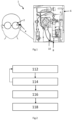
- Figure 3 shows the system 1 for activating a function or a functional test of a medical device according to the disclosure in a schematic representation with an augmented reality guide based on Figure 2 .
- the camera 4 is attached to the AR glasses 2 and covers the defined field of view 6.
- the field of view 6 (corresponds to the representation in Figure 3 ) includes, for example, the dialysis machine 8 (medical device) with the disposables 10 attached to it (e.g., fluid lines, tubes, dialyzer, etc.).
- the windows 122, 124, and 126 are displayed in the field of view, along with arrows representing instructions for handling (e.g., the straight arrow next to window 122 and the semicircular arrow next to window 124).
- the first window 122 can contain instructions such as, for example, "Guide the tube through the connector.”
- the second window 124 can contain instructions such as, for example, "Insert the blood tube into the blood pump as shown in the video.”
- the third window 126 at the bottom can have a different size than one of the other windows, for example, larger, and a video can be shown in this window, for example, a YouTube video.
- Figure 4 shows a schematic representation of a possible interaction between the AR device, the user and the CPU.
- the procedure is divided into Procedural steps performed by the AR device (see column 128), the procedural steps performed by the user (see column 130) and the procedural steps performed by the medical device (see column 132).
- step 134 the AR device or the CPU attached to it detects that the task of connecting the disposables has been recognized.
- step 136 the medical device is informed that the task of connecting the disposables has been recognized.
- step 138 the medical device prepares for a functional test.
- step 140 the user then installs the cables.
- step 142 the AR device detects that the lines have been connected and can additionally or alternatively check for incorrectly connected lines.
- step 144 the medical device is informed that the disposables have been installed.
- the medical device performs a functional test of the leads in step 146.
- step 148 the medical device informs the AR device about the positive test or result.
- step 150 the result is displayed on the AR device. If the result is negative, the steps from step 142 are repeated.
- step 152 the next step is displayed in step 152 in the AR device.
Landscapes
- Health & Medical Sciences (AREA)
- Heart & Thoracic Surgery (AREA)
- Engineering & Computer Science (AREA)
- Biomedical Technology (AREA)
- Vascular Medicine (AREA)
- General Health & Medical Sciences (AREA)
- Public Health (AREA)
- Veterinary Medicine (AREA)
- Animal Behavior & Ethology (AREA)
- Life Sciences & Earth Sciences (AREA)
- Hematology (AREA)
- Anesthesiology (AREA)
- Emergency Medicine (AREA)
- Urology & Nephrology (AREA)
- Cardiology (AREA)
- Primary Health Care (AREA)
- Medical Informatics (AREA)
- Epidemiology (AREA)
- General Business, Economics & Management (AREA)
- Business, Economics & Management (AREA)
- External Artificial Organs (AREA)
- User Interface Of Digital Computer (AREA)
Description
- Die Offenbarung betrifft ein Verfahren und eine Vorrichtung zur Funktionsprüfung von medizinischen Geräten.
- Unter erweiterter Realität (auch englisch augmented reality, kurz AR) versteht man die computergestützte Erweiterung der Realitätswahrnehmung. Diese Information kann alle menschlichen Sinnesmodalitäten ansprechen. Häufig wird jedoch unter erweiterter Realität nur die visuelle Darstellung von Informationen verstanden, also die Ergänzung von Bildern oder Videos mit computergenerierten Zusatzinformationen oder virtuellen Objekten mittels Einblendung/Überlagerung. Bei Fußball-Übertragungen ist erweiterte Realität beispielsweise das Einblenden von Entfernungen bei Freistößen mithilfe eines Kreises oder einer Linie.
- Ein Dialysegerät/ eine Dialysemaschine ermöglicht die patientenspezifische Entfernung gelöster Substanzen (z. B. Harnstoff, Kreatinin, Vitamin B12 oder β2-Mikroglobulin) sowie gegebenenfalls eines definierten Wasseranteils aus dem Blut bei Nierenersatzbehandlungen. Dialysegeräte werden sowohl für die Hämodialyse als auch die Hämodiafiltration eingesetzt. Grundsätzlich kann man Dialysegeräte in folgende Module einteilen: Extrakorporaler Blutkreislauf, Dialysierflüssigkeitskreislauf, Desinfektionseinheit, Bedienteil und Netzteil. Darüber hinaus kommen Verbrauchsmaterialien, sogenannte Disposables, während der Behandlung zum Einsatz. Diese Disposables sind zum Beispiel Dialysierflüssigkeitskanülen, Blutschlauchsysteme, Dialysatoren, Dialysekonzentrate usw.
- Ein Nachteil im Stand der Technik ist es, dass Pflegekräfte ein spezielles Anwendertraining benötigen, um Dialysegeräte zu benutzen bzw. die Disposables richtig an das Dialysegerät anzubringen. Dieses Anwendertraining ist für jede neue Generation einer Dialysemaschine notwendig.
- Aus der
US 2019/0064520 A1 ist eine Augmented-Reality-Unterstützung während einer Dialysebehandlung bekannt. - Beschreibung der Erfindung Die Aufgabe der Offenbarung ist es, ein schnelles, effizientes und fehlerfreies Anlegen der Disposables sowie einen schnellen und sicheren Selbsttest durch interne und externe Informationen zu ermöglichen.
- Gelöst wird diese Aufgabe durch die Merkmale der Ansprüche 1 und 7. Vorteilhafte Ausführungsformen bzw. Weiterbildungen sind in den Unteransprüchen beansprucht Neben dieser beanspruchten Erfindung beschreibt das vorliegende Dokument auf allgemeinere Weise (ohne es jedoch auf diese allgemeinere Weise zu beanspruchen) : ein Verfahren zur Aktivierung einer Funktion einer Vorrichtung, vorzugsweise medizinischen Vorrichtung, aufweisend die Schritte:
- Erfassen des Ist-Zustandes der Vorrichtung mittels einer Kamera vorzugsweise an einem AR-Device, insbesondere einer AR-Brille oder einer AR-Sichtschutzscheibe,
- Vergleichen des Ist-Zustandes der Vorrichtung mit einem Soll-Zustand der Vorrichtung durch wenigstens eine CPU, die mit der Kamera in Verbindung steht,
- Senden eines Befehls für den Start einer Funktion, vorzugsweise eines Funktionstests, von der CPU an die Vorrichtung, auf Basis des Vergleichs,
- Aktivieren einer Funktion, vorzugsweise eines Funktionstests, der Vorrichtung, aufgrund des Befehls.
- In anderen Worten ausgedrückt erkennt die wenigstens eine CPU/ Recheneinheit, die die Bilder von der Kamera erhält, den Zustand/ Aufbau/ Setting/ Montagestufe einer medizinischen Vorrichtung, vorzugsweise einer Dialysemaschine. Dabei können die Kamera und gegebenenfalls auch die CPU/Recheneinheit in dem AR-Device, vorzugsweise an einer Smart-Glass-Brille untergebracht bzw. in diese integriert sein.
- Die wenigstens eine CPU/ Recheneinheit blendet die vom Anwender durchzuführenden erforderlichen Schritte z.B. zum korrekten Verbinden von Disposables mit der medizinischen Vorrichtung in ein Sichtfeld des AR-Device insbesondere einer Smart-Glas-Brille ein (vorzugsweise blendet ein Projektor die Informationen ein, der mit der CPU in Verbindung steht).
- Wenn die CPU über die an dem AR-Device angeordnete Kamera erkennt, dass ein Aufbau richtig beendet ist, startet die CPU über eine vorzugsweise kabellose Verbindung vorzugsweise mittels Bluetooth oder WLAN (ZigBee, NFC, Mobilfunk) die Vorrichtung zu einem Funktionstest.
- Alternativ oder zusätzlich ist die CPU oder eine Datenübertragungsvorrichtung an dem AR-Device dafür vorgesehen und angepasst die Bilder der Kamera an eine andere, zweite bzw. stationäre CPU zu senden. Vorzugsweise befindet sich diese in einer/ der medizinischen Vorrichtung, sie kann aber auch extern von dem AR-Device und/oder der medizinischen Vorrichtung sein, z.B. in Form eines PCs der mit der medizinischen Vorrichtung verbunden ist. Diese zweite bzw. stationäre CPU hat vorzugsweise eine größere Rechenleistung als die erste CPU, die gegebenenfalls an dem AR-Device angeordnet wird/ ist. Die zweite CPU verarbeitet die empfangenen Daten und sendet verarbeitete Daten wieder an die erste CPU der Datenübertragungsvorrichtung an das AR-Device, das dann veranlasst, dass die Informationen in dem Sichtfeld des AR-Devices angezeigt werden. In anderen Worten ausgedrückt dient die erste CPU an dem AR-Device zur Übertragung der Daten und steuert die Anzeige von Informationen, wohingegen die zweite externe bzw. stationäre CPU als Datenverarbeitungseinheit sowie Recheneinheit zum Verarbeiten der aufgenommenen Bilder dient und daraus z.B. Handlungsschritte ableitet, die sie wie eben beschrieben an die erste CPU als konkrete anzuzeigende Informationen zurückgibt.
- Vorzugsweise ist die Vorrichtung eine medizinische Vorrichtung und besonders bevorzugt ein Dialysegerät, eine Dialysemaschine, eine Spritzenpumpe oder dergleichen.
- Vorzugsweise ist das AR-Device ein Produkt der Klasse der Wearables (Wearable Computing). Ein Wearable/ Wearable Computer ist während der Anwendung am Körper des Benutzers befestigt oder in die Kleidung integriert. Vorzugsweise weist das AR-Device gemäß der Offenbarung ein optisches Display auf, das in dem Sichtfeld eines Anwenders integriert ist, sowie eine CPU und/oder eine Datenübermittlungseinheit. Das AR- Device ist besonders bevorzugt eine AR-Brille, Smart-Glass-Brille, Smartglasses, eine Datenbrille oder ein Head-up-Display. Eine Smart-Glass-Brille oder Smartglasses (oder umgangssprachlich: Datenbrille) ist dabei vorzugsweise ein tragbarer (wearable) Computer an einer Brille, der Informationen zum Sichtfeld des Benutzers hinzufügt. Weiter vorzugsweise weist die Brille auch die Kamera auf. Zusätzlich oder alternativ kann die Brille auch eine Datenübertragungseinheit aufweisen. Die Brille ermöglicht augmented Reality bzw. mixed Reality.
- Vorzugsweise ist die Kamera eine Digitalkamera. Neben der diskreten Anzeige von Informationen auf dem Display des AR-Devices können Informationen auch mit dem aufgenommenen Bild der integrierten Digitalkamera kombiniert werden. Dazu können Daten aus dem Internet unmittelbar bezogen und versendet werden.
- Vorzugsweise ist die Kamera mit der ersten (AR-Device integrierten) CPU und/ oder der zweiten stationären bzw. separaten CPU in datentechnischer Verbindung, vorzugsweise drahtlos, z.B. über Bluetooth, W-LAN oder dergleichen. Alternativ oder zusätzlich kann die erste CPU an dem AR-Device mit einer zweiten externen CPU in datentechnischer Verbindung, vorzugsweise drahtlos, z.B. über Bluetooth, W-LAN oder dergleichen stehen. Vorzugsweise ist die CPU an dem AR-Device mit der medizinischen Vorrichtung in datentechnischer Verbindung, vorzugsweise drahtlos, z.B. über Bluetooth, W-LAN oder dergleichen. Bei der zweiten CPU handelt es sich bevorzugt um eine in der medizinischen Vorrichtung zu Steuerungszwecken derselben bereits vorhandene Recheneinheit/ CPU.
- Vorzugsweise findet der Vergleich des Ist-Zustands der Vorrichtung mit einem Soll-Zustand der Vorrichtung mittels eines Bilderkennungsalgorithmus statt, der auf einem Speichermedium der CPU gespeichert ist. Wobei dies die erste CPU an dem AR-Device sein kann, oder wenigstens eine optionale zweite CPU in der medizinischen Vorrichtung oder extern von dem AR-Device und/ oder der medizinischen Vorrichtung.
- Vorzugsweise führt die Vorrichtung einen Selbsttest/ Funktionstest/ Druckselbsttest oder dergleichen in Erwiderung auf den Input der Kamera durch. Dabei kann der Funktionstest nach einer manuellen Bestätigung an der medizinischen Vorrichtung selbst, oder mittels einer Geste, die von der Kamera und der CPU erkannt wird, oder einfach nach einer vorgegebenen Zeit aktiviert werden. Beispielsweise kann nach Anschluss der Drucksensoren ein Druckselbsttest gestartet werden. Bei dem Druckselbsttest werden vorzugsweise die angeschlossenen/ montierten Disposables an der medizinischen Vorrichtung von dieser unter Druck gesetzt. Falls ein vorbestimmter Druckabfall von Drucksensoren ermittelt wird, liegt eine Leckage bzw. ein fehlerhafter Anschluss vor und die medizinische Vorrichtung gibt eine Fehlermeldung/ Signal aus.
- Der Ist-Zustand bezeichnet den aktuellen Zustand inwieweit die Disposables in die medizinische Vorrichtung eingebaut sind zu einem ersten Zeitpunkt T1. Der Soll-Zustand bezeichnet den fertigen und richtigen Zustand der Disposables in der medizinischen Vorrichtung. Vorzugsweise wird der Aufrüstvorgang, bei dem die Disposables in die medizinische Vorrichtung eingebaut werden, in verschiedene Teilschritte zerlegt und diese werden, vorzugsweise jeweils einzeln oder im Gesamten, angeleitet, überwacht (Vergleich zwischen aktuellem Ist-Zustand und Soll-Zustand des Teilschrittes) und dann ,getestet'.
- Das Senden eines Befehls für den Start einer Funktion, vorzugsweise eines Funktionstests, von der CPU an die Vorrichtung, auf Basis des Vergleichs (bzw. im Anschluss an den Vergleich) geschieht vorzugsweise bei einem positiven Vergleich, also wenn der Ist-Zustand dem Soll-Zustand entspricht. Bei einem negativen Vergleich, also wenn der Ist-Zustand nicht dem Soll-Zustand entspricht, wird auf den Befehl hin eine entsprechende Funktion aktiviert, vorzugsweise eine Fehlermeldung in dem AR-Device oder der medizinischen Vorrichtung.
- Vorzugsweise ist das Verfahren dadurch gekennzeichnet, dass es des Weiteren den Schritt aufweist: Anzeigen des Funktionsergebnisses in dem AR-Device. In anderen Worten ausgedrückt werden die einzelnen Einbauschritte der Disposables in dem AR-Device angezeigt, in Abhängigkeit vom Vergleich des Ist-Zustands mit dem Soll-Zustand. Alternativ oder zusätzlich kann ein Ergebnis des Funktionstests, zum Beispiel der vorherrschende Druck in den angeschlossenen Disposables angezeigt werden.
- Vorzugsweise ist das Verfahren dadurch gekennzeichnet, dass das Verfahren des Weiteren den Schritt aufweist: Senden eines Funktionstestergebnisses an die CPU und/oder Einblenden der erforderlichen Schritte, vorzugsweise in Form von Markierungen, Animationen und/ oder Nachrichten, zum Erreichen des Soll-Zustandes der Vorrichtung in dem AR-Device. In anderen Worten ausgedrückt sendet die medizinische Vorrichtung, in der zum Beispiel die zweite bzw. separate bzw. stationäre CPU und/ oder eine Datenübertragungseinheit vorhanden ist ein Signal an die erste CPU oder Datenübertragungseinheit in dem AR-Device. Analog dazu wird dann, wie vorstehend bereits erläutert, in Erwiderung auf das Signal der medizinischen Vorrichtung, das Ergebnis der Funktion (Funktionsergebnis/ Funktionsresultat) angezeigt.
- Vorzugsweise ist das Verfahren dadurch gekennzeichnet, dass es des Weiteren den Schritt aufweist: Sperren weiterer Funktionen bei einer negativen Funktion (negativ ausgefallenem Funktionstest). In anderen Worten ausgedrückt, wenn der Ist-Zustand nicht mit dem Soll-Zustand übereinstimmt, sperrt die medizinische Vorrichtung weitere Funktionen, bis der Vergleich positiv ist.
- Vorzugsweise ist das Verfahren dadurch gekennzeichnet, dass ein Funktionstest ein Drucktest ist, der einen zu Testzwecken aufgebauten (Leitungs-) Druck in Disposables misst.
- Vorzugsweise werden die Schritte graphisch auf einem Display dargestellt. Bevorzugt werden in dem AR-Device die erforderlichen Schritte mittels bildlicher Darstellungen, die ganz oder teilweise animiert sein können und/oder mittels Schrift im Sichtfeld des Anwenders dargestellt. In anderen Worten ausgedrückt können Markierungen, Animationen und/oder Nachrichten in das Sichtfeld projiziert werden.
- Vorzugsweise ist die medizinische Vorrichtung in datentechnischem Kontakt mit der CPU, die sich in dem AR-Device, der medizinischen Vorrichtung, einem PC oder anderweitig extern befinden kann.
- Die Offenbarung betrifft des Weiteren ein System zur Aktivierung einer Vorrichtungs-Funktion, vorzugsweise eines Funktionstests, aufweisend wenigstens eine Kamera, wenigstens eine CPU die in datentechnischer Verbindung mit der Kamera steht, und vorzugsweise wenigstens eine Vorrichtung, beispielsweise eine medizinische Vorrichtung, insbesondere eine Dialysemaschine, die wiederum in datentechnischer Verbindung mit der CPU steht oder bringbar ist, wobei die CPU ein Speichermedium aufweist oder mit einer externen CPU datentechnisch verbindbar ist, auf dem/ der die folgenden Schritte gespeichert sind:
- Erkennen eines Ist-Zustandes der Vorrichtung mittels der Kamera, die vorzugsweise an einem AR-Device angeordnet ist,
- Vergleichen des Ist-Zustandes der Vorrichtung mit einem Soll-Zustand der Vorrichtung durch die CPU, die mit der Kamera in Verbindung steht,
- Senden eines Befehls für den Start einer Vorrichtungs-Funktion, vorzugsweise eines Vorrichtungs-Funktionstests, (von der CPU) an die Vorrichtung, wenn der Ist-Zustand einem vorgegebenen Soll-Zustand entspricht,
- Aktivieren der Vorrichtungs-Funktion, vorzugsweise des Vorrichtungs-Funktionstests, der Vorrichtung, aufgrund des Befehls.
- Vorzugsweise ist die Kamera an/ in einem AR-Device angebracht, das vorgesehen und angepasst ist, die Ergebnisse des Funktionstests und/oder eine Einbauanleitung, vorzugsweise nach dem Anzeigeprinzip eines Head-UP-Displays, darzustellen.
- Die Offenbarung betrifft des Weiteren vorzugsweise ein Verfahren und eine Vorrichtung zur Aktivierung einer Funktion einer Vorrichtung, vorzugsweise medizinischen Vorrichtung, aufweisend die Schritte: Erkennen des Ist-Zustandes der Vorrichtung mittels einer Kamera, die vorzugsweise an einem AR-Device angeordnet ist. Vergleichen des Ist-Zustandes der Vorrichtung mit einem Soll-Zustand der Vorrichtung durch eine CPU, die mit der Kamera in Verbindung steht. Senden eines Befehls für den Start einer Vorrichtungs-Funktion, vorzugsweise eines Vorrichtungs-Funktionstests, (von der CPU) an die Vorrichtung, wenn der Ist-Zustand gemäß visueller Erkennung einem vorgegeben Soll-Zustand entspricht bzw. zu entsprechen scheint. Aktivieren einer Vorrichtungs-Funktion, vorzugsweise eines Vorrichtungs-Funktionstests, in Ansprechen(Erwiderung) auf den Befehl.
- Zusammengefasst betrifft die Offenbarung ein Verfahren zur Aktivierung oder Durchführung eines Funktionstests einer Blutbehandlungsvorrichtung, vorzugsweise Dialysemaschine, aufweisend die Schritte: Erfassen eines Ist-Zustandes der Blutbehandlungsvorrichtung mittels einer Kamera, welche vorzugsweise in/an einer Augmented-Reality-Vorrichtung, vorzugsweise einer Augmented-Reality-Brille, vorgesehen bzw. angebracht ist; Vergleichen des Ist-Zustandes der Blutbehandlungsvorrichtung mit einem Soll-Zustand der Blutbehandlungsvorrichtung durch eine Steuereinheit (CPU), die mit der Kamera in Verbindung steht; Senden eines Befehls für den Start des Funktionstests von der Steuereinheit (CPU) an die Blutbehandlungsvorrichtung auf Basis des Vergleichs; und Aktivieren des Funktionstests der Blutbehandlungsvorrichtung aufgrund des Befehls.
- Bevorzugt weist das Verfahren ferner die Schritte auf: Senden eines Funktionstestergebnisses an die Steuereinheit (CPU); und Anzeigen des Funktionstestergebnisses in einer Augmented-Reality-Vorrichtung.
- Weiter bevorzugt weist das Verfahren ferner den Schritt auf: Einblenden von noch erforderlichen durchzuführenden Schritten zum Erreichen des Soll-Zustandes der Blutbehandlungsvorrichtung in der Augmented-Reality-Vorrichtung, vorzugsweise in Form von Markierungen, Animationen und/ oder Nachrichten.
- Es ist von Vorteil, wenn das Verfahren weiterhin den Schritt aufweist: Sperren weiterer Funktionstests bei einem negativen Funktionstestergebnis.
- In vorteilhafter Weise ist der Funktionstest ein, vorzugsweise automatisierter, Selbsttest der Blutbehandlungsvorrichtung zum Überprüfen von von einem Nutzer vorgenommenen Aufrüstungshandlungen bei einer Aufrüstung der Blutbehandlungsvorrichtung.
- Bevorzugt ist der Funktionstest ein Drucktest, der einen zu Testzwecken temporär aufgebauten Druck in Einmalprodukten, insbesondere Fluidleitungen, welche an/in der Blutbehandlungsvorrichtung angebracht bzw. vorgesehen sind, misst.
- Weiterhin betrifft die Offenbarung zusammengefasst ein System aufweisend wenigstens eine Kamera, wenigstens eine Steuereinheit (CPU), die in datentechnischer Verbindung mit der Kamera steht oder bringbar ist, und wenigstens eine Blutbehandlungsvorrichtung, insbesondere Dialysemaschine, die wiederum in datentechnischer Verbindung mit der Steuereinheit (CPU) steht oder bringbar ist, wobei die Steuereinheit (CPU) eingerichtet ist, einen Ist-Zustand der Blutbehandlungsvorrichtung (8) mittels der Kamera (4), die vorzugsweise in/an einer Augmented-Reality-Vorrichtung (2), insbesondere einer Augmented-Reality-Brille oder einer Augmented-Reality-Sichtschutzscheibe, vorgesehen bzw. angeordnet ist, zu erfassen, den Ist-Zustand der Blutbehandlungsvorrichtung (8) mit einem Soll-Zustand der Blutbehandlungsvorrichtung (8) zu vergleichen, einen Befehl für den Start eines Funktionstests an die Blutbehandlungsvorrichtung (8) auf der Basis des Vergleichs zu senden, und den Funktionstest der Blutbehandlungsvorrichtung (8) aufgrund des Befehls zu aktivieren.
- Bevorzugt ist die Kamera an/in einer Augmented-Reality-Vorrichtung angebracht bzw. vorgesehen, wobei die Augmented-Reality-Vorrichtung eingerichtet ist, ein Funktionstestergebnis und/oder weitere von einem Anwender durchzuführende Schritte darzustellen.
- Weiter bevorzugt ist der Funktionstest ein, vorzugsweise automatisierter, Selbsttest der Blutbehandlungsvorrichtung zum Überprüfen von von einem Nutzer vorgenommenen Aufrüstungshandlungen bei einer Aufrüstung der Blutbehandlungsvorrichtung.
- Es ist von Vorteil, wenn der Funktionstest ein Drucktest ist, der einen zu Testzwecken temporär aufgebauten Druck in Einmalprodukten, insbesondere Fluidleitungen, welche an/in der Blutbehandlungsvorrichtung angebracht bzw. vorgesehen sind, misst.
- Im Nachfolgenden wird die vorliegende Offenbarung anhand eines bevorzugten Ausführungsbeispiels unter Bezugnahme auf die begleitenden Figuren näher erläutert.
-
-
Figur 1 zeigt das System zur Aktivierung einer Funktion einer Vorrichtung gemäß der Offenbarung in einer schematischen Darstellung. -
Figur 2 zeigt das Verfahren zur Aktivierung einer Funktion einer Vorrichtung. -
Figur 3 zeigt das System zur Aktivierung einer Funktion einer Vorrichtung gemäß der Offenbarung in einer schematischen Darstellung mit einem augmented Reality Guide. -
Figur 4 zeigt eine schematische Darstellung einer möglichen Interaktion zwischen dem AR-Device, dem Anwender und der CPU. -
Figur 1 zeigt ein System 1 zur Aktivierung einer Funktion oder eines Funktionstests einer medizinischen Vorrichtung gemäß der Offenbarung in einer schematischen Darstellung. An/ in einer AR-Brille (AR-Device) 2 ist eine Kamera 4 angebracht, die ein definiertes Sichtfeld 6 umfasst. Das Sichtfeld 6 umfasst z.B. eine Dialysemaschine 8, als medizinische Vorrichtung, mit daran befestigten Disposables 10, die in diesem Fall die zum Auswechseln bestimmten Leitungen (Blutleitungen, Dialysierflüssigkeitsleitungen) und ein Dialysator der Dialysemaschine 8 sind. Des Weiteren ist wenigstens eine CPU vorgesehen, die mit der Kamera 4 in Verbindung steht. Diese CPU kann eine stationäre, gegebenenfalls Vorrichtungs-eigene Recheneinheit oder eine mobile AR-Brille-eigene Recheneinheit sein, wobei im Fall einer stationären Recheneinheit die AR-Brille lediglich eine Datenübertragungseinheit aufweisen kann. Die CPU (nicht dargestellt) vorzugsweise in der Dialysemaschine 8 und/oder an der AR-Brille 2 erkennt die Ist-Anordnung (Ist-Zustand) der Disposables 10 und vergleicht sie mittels eines Bilderkennungsalgorithmus mit einer Soll-Anordnung (Soll-Zustand), welche in einem Speichermedium der CPU abgespeichert ist/ oder der per W-LAN abgerufen wird. Erkennt der Algorithmus, dass die Disposables 10 falsch/ unvollständig angebracht sind, wird ein Korrekturschritt im Sichtfeld des Anwenders, das dem Sichtfeld 6 der Kamera 4 entspricht, in der AR-Brille 2 eingeblendet. Erkennt der Algorithmus, dass die Disposables 10 richtig angebracht sind, gibt die CPU vorzugsweise mittels W-LAN oder Bluetooth oder dergleichen einen Befehl an die Dialysemaschine 8 zur Durchführung einer Funktion oder eines Funktionstests. Ist der Funktionstest positiv, wird dies auf der AR-Brille 2 angezeigt. Ist der Funktionstest negativ, wird ein entsprechend erforderlicher Korrekturschritt auf der AR-Brille 2 angezeigt. -
Figur 2 zeigt das Verfahren zur Aktivierung einer Funktion/ eines Funktionstests einer Vorrichtung (Dialysemaschine 8) unter Einbindung des vorstehenden Systems 1. - In Schritt 112 erkennt die Kamera 4 den Ist-Zustand der Dialysemaschine 8. In anderen Worten ausgedrückt nimmt die Kamera 4 ein oder mehrere Bilder auf, das/ die den aktuellen Ist-Zustand darstellt/ dokumentieren.
- In Schritt 114 vergleicht die CPU den Ist-Zustand der Dialysemaschine 8 mit einem Soll-Zustand der Dialysemaschine 8. In anderen Worten ausgedrückt wird das Bild der Kamera 4 aus dem Schritt 112 mit einem gespeicherten Bild auf der CPU verglichen und mittels Mustererkennung bestimmt, ob der Ist-Zustand dem Soll-Zustand entspricht. Ist ein solcher Vergleich nicht möglich, etwa aufgrund eines ungeeigneten Bildes, wird der Schritt 112 erneut ausgeführt, bis ein Bild erhalten wird, das den Ist-Zustand zeigt und mit einem Soll-Zustand verglichen werden kann. Dieser Wiederholungsvorgang bzw. das Vorliegen eines ungeeigneten Bildes kann auf dem AR-Device angezeigt werden etwa mit einer bevorzugten Nachricht/ Korrekturanweisung, die zum Beispiel angibt, dass der Blickwinkel geändert werden muss. Kommt ein Vergleich des Ist-Zustandes mit Soll-Zustand zustande, folgt der nächste Schritt.
- In Schritt 116 sendet die CPU einen Befehl zum Start eines Funktionstests an die Dialysemaschine 8. In anderen Worten ausgedrückt, sobald die CPU den Ist-Zustand mit dem Soll-Zustand positiv verglichen und festgestellt hat, ergeht ein Befehl an die medizinische Vorrichtung/ Dialysemaschine zur Ausführung einer Funktion/ eines Funktionstests zur Überprüfung, ob die Montage funktional korrekt ausgeführt wurde.
- In Schritt 118 führt die Dialysemaschine 8 die Funktion bzw. den Funktionstest durch. In anderen Worten ausgedrückt erfolgt in Erwiderung auf den Befehl der CPU eine entsprechende Aktion an der Dialysemaschine 8.
- In Schritt 120 sendet die Dialysemaschine 8 das Ergebnis des Funktionstests an die CPU bzw. misst die CPU das Testergebnis aus, die dann das Ergebnis graphisch auf der AR-Brille 2 darstellt. Vorzugsweise ist das Ergebnis dabei der Druck/ Druckverlauf, der in den Disposables/ Leitungen herrscht/ testweise induziert wurde.
-
Figur 3 zeigt das System 1 zur Aktivierung einer Funktion bzw. eines Funktionstests einer medizinischen Vorrichtung gemäß der Offenbarung in einer schematischen Darstellung mit einem augmented Reality Guide in Anlehnung anFigur 2 . An der AR-Brille 2 ist die Kamera 4 angebracht, die das definierte Sichtfeld 6 umfasst. Das Sichtfeld 6 (entspricht der Darstellung inFigur 3 ) umfasst z.B. die Dialysemaschine 8 (medizinische Vorrichtung) mit den daran befestigten Disposables 10 (z.B. Fluidleitungen, Schläuche, Dialysator, etc.). In dem Sichtfeld werden die Fenster 122, 124 und 126 eingeblendet und Pfeile, die Instruktionen für die Handhabung darstellen (z.B. der gerade Pfeil neben Fenster 122 und der halbrunde Pfeil neben Fenster 124). Das erste Fenster 122 kann Instruktionen enthalten wie zum Beispiel "Führen des Schlauchs durch den Verbinder". Das zweite Fenster 124 kann Instruktionen enthalten wie zum Beispiel "Einführen des Blutschlauches in die Blutpumpe wie in dem Video gezeigt". Das dritte Fenster 126 an dem unteren Rand kann eine Größe aufweisen, die unterschiedlich zu einem der anderen Fenster ist, zum Beispiel größer, und in diesem Fenster kann ein Video gezeigt werden, zum Beispiel ein Youtube-Video. -
Figur 4 zeigt eine schematische Darstellung einer möglichen Interaktion zwischen dem AR-Device, dem Anwender und der CPU. InFigur 4 ist das Verfahren aufgeteilt in die Verfahrensschritte, die das AR-Device durchführt (siehe Spalte 128), in die Verfahrensschritte, die der Anwender durchführt (siehe Spalte 130) und in die Verfahrensschritte, die die medizinische Vorrichtung durchführt (siehe Spalte 132). - In Schritt 134 wird von dem AR-Device bzw. der daran befestigten CPU erkannt, dass die Aufgabe Verbinden der Disposables erkannt wurde.
- In Schritt 136 wird die medizinische Vorrichtung informiert, dass die Aufgabe Verbinden der Disposables erkannt wurde.
- In Schritt 138 bereitet sich die medizinische Vorrichtung auf einen Funktionstest vor.
- In Schritt 140 werden dann vom Anwender die Leitungen eingebaut.
- In Schritt 142 erkennt das AR-Device, dass die Leitungen angeschlossen wurden und kann zusätzlich oder alternativ nach falsch angeschlossenen Leitungen prüfen.
- In Schritt 144 wird die medizinische Vorrichtung informiert, dass die Disposables eingebaut wurden.
- Die medizinische Vorrichtung führt in Schritt 146 einen Funktionstest der Leitungen durch.
- In Schritt 148 informiert die medizinische Vorrichtung das AR-Device, über den positiven Test bzw. das Resultat.
- In Schritt 150 wird das Resultat in dem AR-Device angezeigt. Falls das Resultat negativ ist, werden die Schritte ab Schritt 142 wiederholt.
- Wenn alles in Ordnung ist, wird in Schritt 152 in dem AR-Device der nächste Schritt angezeigt.
Claims (10)
- Verfahren zur Aktivierung oder Durchführung eines Funktionstests einer Blutbehandlungsvorrichtung (8) aufweisend die Schritte:• Erfassen eines Ist-Zustandes der Blutbehandlungsvorrichtung (8) mittels einer Kamera (4), welche in/an einer Augmented-Reality-Vorrichtung vorgesehen bzw. angebracht ist,• Vergleichen des Ist-Zustandes der Blutbehandlungsvorrichtung (8) mit einem Soll-Zustand der Blutbehandlungsvorrichtung (8) durch eine Steuereinheit (CPU), die mit der Kamera (4) in Verbindung steht,• Senden eines Befehls für den Start des Funktionstests von der Steuereinheit (CPU) an die Blutbehandlungsvorrichtung (8) auf Basis des Vergleichs,• Aktivieren des Funktionstests der Blutbehandlungsvorrichtung (8) aufgrund des Befehls.
- Verfahren nach Anspruch 1, gekennzeichnet ferner durch die Schritte:• Senden eines Funktionstestergebnisses an die Steuereinheit (CPU),• Anzeigen des Funktionstestergebnisses in der Augmented-Reality-Vorrichtung (2).
- Verfahren nach Anspruch 1 oder 2, gekennzeichnet ferner durch den Schritt:• Einblenden von noch erforderlichen durchzuführenden Schritten zum Erreichen des Soll-Zustandes der Blutbehandlungsvorrichtung (8) in der Augmented-Reality-Vorrichtung (2).
- Verfahren nach einem der Ansprüche 1 bis 3, gekennzeichnet ferner durch den Schritt:• Sperren weiterer Funktionstests bei einem negativen Funktionstestergebnis.
- Verfahren nach einem der Ansprüche 1 bis 4, dadurch gekennzeichnet, dass der Funktionstest ein Selbsttest der Blutbehandlungsvorrichtung (8) zum Überprüfen von von einem Nutzer vorgenommenen Aufrüstungshandlungen bei einer Aufrüstung der Blutbehandlungsvorrichtung (8) ist.
- Verfahren nach einem der Ansprüche 1 bis 5, dadurch gekennzeichnet, dass der Funktionstest ein Drucktest ist, der einen zu Testzwecken temporär aufgebauten Druck in Einmalprodukten, welche an/in der Blutbehandlungsvorrichtung (8) angebracht bzw. vorgesehen sind, misst.
- System aufweisend wenigstens eine Kamera (4), wenigstens eine Steuereinheit (CPU), die in datentechnischer Verbindung mit der Kamera (4) steht oder bringbar ist, und wenigstens eine Blutbehandlungsvorrichtung (8), die wiederum in datentechnischer Verbindung mit der Steuereinheit (CPU) steht oder bringbar ist, dadurch gekennzeichnet, dass die Steuereinheit (CPU) eingerichtet ist,• einen Ist-Zustand der Blutbehandlungsvorrichtung (8) mittels der Kamera (4), die in/an einer Augmented-Reality-Vorrichtung (2) vorgesehen bzw. angeordnet ist, zu erfassen,• den Ist-Zustand der Blutbehandlungsvorrichtung (8) mit einem Soll-Zustand der Blutbehandlungsvorrichtung (8) zu vergleichen,• einen Befehl für den Start eines Funktionstests an die Blutbehandlungsvorrichtung (8) auf der Basis des Vergleichs zu senden, und• den Funktionstest der Blutbehandlungsvorrichtung (8) aufgrund des Befehls zu aktivieren.
- System nach Anspruch 7, dadurch gekennzeichnet, dass die Kamera (4) an/in der Augmented-Reality-Vorrichtung (2) angebracht bzw. vorgesehen ist, wobei die Augmented-Reality-Vorrichtung (2) eingerichtet ist, ein Funktionstestergebnis und/oder weitere von einem Anwender durchzuführende Schritte darzustellen.
- System nach Anspruch 7 oder 8, dadurch gekennzeichnet, dass der Funktionstest ein Selbsttest der Blutbehandlungsvorrichtung (8) zum Überprüfen von von einem Nutzer vorgenommenen Aufrüstungshandlungen bei einer Aufrüstung der Blutbehandlungsvorrichtung (8) ist.
- System nach einem der Ansprüche 7 bis 9, dadurch gekennzeichnet, dass der Funktionstest ein Drucktest ist, der einen zu Testzwecken temporär aufgebauten Druck in Einmalprodukten, welche an/in der Blutbehandlungsvorrichtung (8) angebracht bzw. vorgesehen sind, misst.
Applications Claiming Priority (2)
| Application Number | Priority Date | Filing Date | Title |
|---|---|---|---|
| DE102019120999.4A DE102019120999A1 (de) | 2019-08-02 | 2019-08-02 | Verfahren und Vorrichtung zur Aktivierung einer Funktion einer Vorrichtung |
| PCT/EP2020/071234 WO2021023574A1 (de) | 2019-08-02 | 2020-07-28 | Extrakorporale-blutbehandlunssystem mit augmented-reality vorrichtung zur überprüfung der montage und mit funktionstest |
Publications (2)
| Publication Number | Publication Date |
|---|---|
| EP4007616A1 EP4007616A1 (de) | 2022-06-08 |
| EP4007616B1 true EP4007616B1 (de) | 2025-05-07 |
Family
ID=71842687
Family Applications (1)
| Application Number | Title | Priority Date | Filing Date |
|---|---|---|---|
| EP20746969.3A Active EP4007616B1 (de) | 2019-08-02 | 2020-07-28 | Extrakorporale-blutbehandlunssystem mit augmented-reality vorrichtung zur überprüfung der montage und mit funktionstest |
Country Status (6)
| Country | Link |
|---|---|
| US (1) | US12057223B2 (de) |
| EP (1) | EP4007616B1 (de) |
| JP (1) | JP7608431B2 (de) |
| CN (1) | CN114206413B (de) |
| DE (1) | DE102019120999A1 (de) |
| WO (1) | WO2021023574A1 (de) |
Families Citing this family (19)
| Publication number | Priority date | Publication date | Assignee | Title |
|---|---|---|---|---|
| GB2536650A (en) | 2015-03-24 | 2016-09-28 | Augmedics Ltd | Method and system for combining video-based and optic-based augmented reality in a near eye display |
| US12521201B2 (en) | 2017-12-07 | 2026-01-13 | Augmedics Ltd. | Spinous process clamp |
| US12458411B2 (en) | 2017-12-07 | 2025-11-04 | Augmedics Ltd. | Spinous process clamp |
| US11980507B2 (en) | 2018-05-02 | 2024-05-14 | Augmedics Ltd. | Registration of a fiducial marker for an augmented reality system |
| US11766296B2 (en) | 2018-11-26 | 2023-09-26 | Augmedics Ltd. | Tracking system for image-guided surgery |
| US12178666B2 (en) | 2019-07-29 | 2024-12-31 | Augmedics Ltd. | Fiducial marker |
| US11980506B2 (en) | 2019-07-29 | 2024-05-14 | Augmedics Ltd. | Fiducial marker |
| US11382712B2 (en) | 2019-12-22 | 2022-07-12 | Augmedics Ltd. | Mirroring in image guided surgery |
| US11389252B2 (en) | 2020-06-15 | 2022-07-19 | Augmedics Ltd. | Rotating marker for image guided surgery |
| US12502163B2 (en) | 2020-09-09 | 2025-12-23 | Augmedics Ltd. | Universal tool adapter for image-guided surgery |
| US12239385B2 (en) | 2020-09-09 | 2025-03-04 | Augmedics Ltd. | Universal tool adapter |
| US11896445B2 (en) | 2021-07-07 | 2024-02-13 | Augmedics Ltd. | Iliac pin and adapter |
| US12150821B2 (en) | 2021-07-29 | 2024-11-26 | Augmedics Ltd. | Rotating marker and adapter for image-guided surgery |
| WO2023021451A1 (en) | 2021-08-18 | 2023-02-23 | Augmedics Ltd. | Augmented reality assistance for osteotomy and discectomy |
| US12374236B2 (en) | 2022-01-27 | 2025-07-29 | Fresenius Medical Care Holdings, Inc. | Dialysis training using dialysis treatment simulation system |
| US12502465B2 (en) | 2022-03-30 | 2025-12-23 | Fresenius Medical Care Holdings, Inc. | Dialysis treatment file simulation and verification system |
| EP4511809A1 (de) | 2022-04-21 | 2025-02-26 | Augmedics Ltd. | Systeme und verfahren zur visualisierung medizinischer bilder |
| WO2024057210A1 (en) | 2022-09-13 | 2024-03-21 | Augmedics Ltd. | Augmented reality eyewear for image-guided medical intervention |
| JP7705973B1 (ja) | 2024-03-07 | 2025-07-10 | 日機装株式会社 | 医療機器、表示方法およびプログラム |
Family Cites Families (20)
| Publication number | Priority date | Publication date | Assignee | Title |
|---|---|---|---|---|
| JP4783228B2 (ja) * | 2006-07-10 | 2011-09-28 | 東レ・メディカル株式会社 | 血液透析装置のプライミング方法および装置 |
| FR2915105A1 (fr) * | 2007-04-19 | 2008-10-24 | Gambro Lundia Ab | Appareil medical de traitement des fluides et procede pour preparer un appareil medical de traitement des fluides. |
| AU2010338284B2 (en) * | 2009-12-28 | 2014-07-24 | Gambro Lundia Ab | Method and device for detecting a configuration of withdrawal and return devices |
| JP5099182B2 (ja) * | 2010-06-24 | 2012-12-12 | 日本電気株式会社 | 確認業務支援システム、サーバ装置、ヘッドマウントディスプレイ装置、ウェアラブル端末、確認業務支援方法およびプログラム |
| DE102011108784A1 (de) * | 2011-07-29 | 2013-01-31 | Fresenius Medical Care Deutschland Gmbh | Verfahren sowie Vorrichtungen zum Überprüfen wenigstens einer Funktion einer medizinischen Funktionseinrichtung |
| US9123155B2 (en) * | 2011-08-09 | 2015-09-01 | Covidien Lp | Apparatus and method for using augmented reality vision system in surgical procedures |
| DE102012109861A1 (de) * | 2012-10-16 | 2014-04-17 | B. Braun Avitum Ag | Patientenwaage mit Kameraüberwachung und Dialysetherapiesystem mit kameraüberwachtem Wiegeablauf |
| US10288881B2 (en) * | 2013-03-14 | 2019-05-14 | Fresenius Medical Care Holdings, Inc. | Wearable interface for remote monitoring and control of a medical device |
| DE102013103335A1 (de) * | 2013-04-03 | 2014-10-09 | B. Braun Avitum Ag | System zur Erfassung eines Zustands einer Dialysatorvorrichtung, und hierfür verwendbare Sensorvorrichtung |
| DE102014100260A1 (de) * | 2014-01-10 | 2015-07-16 | B. Braun Avitum Ag | Extrakorporale Blutbehandlungsmaschine mit Leckageerkennung sowie ein Verfahren zur Erkennung von Leckagen in Dialysierflüssigkeitssystemen |
| DE102014217559A1 (de) * | 2014-09-03 | 2016-03-03 | Olympus Winter & Ibe Gmbh | Benutzerassistenzsystem einer Reinigungs- und Desinfektionseinrichtung |
| US9746913B2 (en) * | 2014-10-31 | 2017-08-29 | The United States Of America As Represented By The Secretary Of The Navy | Secured mobile maintenance and operator system including wearable augmented reality interface, voice command interface, and visual recognition systems and related methods |
| EP3021244A1 (de) * | 2014-11-12 | 2016-05-18 | B. Braun Avitum AG | Blutreinigungsvorrichtungs-Feedbackverfahren |
| US20160206800A1 (en) * | 2015-01-20 | 2016-07-21 | Fresenius Medical Care Holdings, Inc. | Remote monitoring interface device and mobile application for medical devices |
| DE102015217838B4 (de) * | 2015-09-17 | 2018-02-08 | Siemens Healthcare Gmbh | Vorrichtung zur Unterstützung einer Wartung bei medizintechnischen Geräten |
| DE102015122347A1 (de) * | 2015-12-21 | 2017-06-22 | Fresenius Medical Care Deutschland Gmbh | Sensorgesteuerte Displayausgabe für Dialysemaschinen |
| DE102016005213A1 (de) * | 2016-04-28 | 2017-11-02 | Fresenius Medical Care Deutschland Gmbh | Blutbehandlungsmaschine |
| WO2018001994A1 (en) * | 2016-06-30 | 2018-01-04 | Gambro Lundia Ab | Connection test for blood treatment machines i |
| EP3364321A1 (de) * | 2017-02-15 | 2018-08-22 | Fresenius Medical Care Deutschland GmbH | Medizintechnisches gerät für ein simulations- und evaluierungssystem für medizinische behandlungseinrichtungen |
| US10922961B2 (en) * | 2019-03-13 | 2021-02-16 | Fresenius Medical Care Holdings, Inc. | Remote communication with multiple dialysis machines |
-
2019
- 2019-08-02 DE DE102019120999.4A patent/DE102019120999A1/de active Pending
-
2020
- 2020-07-28 US US17/630,683 patent/US12057223B2/en active Active
- 2020-07-28 JP JP2022506547A patent/JP7608431B2/ja active Active
- 2020-07-28 WO PCT/EP2020/071234 patent/WO2021023574A1/de not_active Ceased
- 2020-07-28 CN CN202080055669.4A patent/CN114206413B/zh active Active
- 2020-07-28 EP EP20746969.3A patent/EP4007616B1/de active Active
Also Published As
| Publication number | Publication date |
|---|---|
| JP7608431B2 (ja) | 2025-01-06 |
| US20220319688A1 (en) | 2022-10-06 |
| JP2022543784A (ja) | 2022-10-14 |
| WO2021023574A1 (de) | 2021-02-11 |
| CN114206413B (zh) | 2025-03-18 |
| DE102019120999A1 (de) | 2021-02-04 |
| EP4007616A1 (de) | 2022-06-08 |
| US12057223B2 (en) | 2024-08-06 |
| CN114206413A (zh) | 2022-03-18 |
Similar Documents
| Publication | Publication Date | Title |
|---|---|---|
| EP4007616B1 (de) | Extrakorporale-blutbehandlunssystem mit augmented-reality vorrichtung zur überprüfung der montage und mit funktionstest | |
| EP2912583B1 (de) | Vorrichtung, system und verfahren zur überwachung, informationsanzeige und bedienung von medizinischen fluidmanagementgeräten | |
| DE102015122347A1 (de) | Sensorgesteuerte Displayausgabe für Dialysemaschinen | |
| DE102014212632B4 (de) | Verfahren zum Überwachen eines Betriebs eines Medizingeräts | |
| DE102014226899A1 (de) | Verfahren zum Betreiben eines medizinisch-robotischen Geräts und ein medizinisch-robotisches Gerät | |
| WO2020173983A1 (de) | Verfahren und vorrichtung zum überwachen eines industriellen prozessschrittes | |
| DE102014008852B4 (de) | Kalibrierung eines Kraftfahrzeug-Eyetrackingsystems | |
| DE102010013885A1 (de) | Mobile Wartungseinheit | |
| EP3433776B1 (de) | Entferntes steuern von meldungen für ein dialysegerät | |
| EP3966084A1 (de) | Verfahren zum durchführen eines rangiervorgangs eines kraftfahrzeugs mit aufmerksamkeitsbeurteilung eines nutzers sowie rangierassistenzsystem für ein kraftfahrzeug | |
| EP3374892B1 (de) | Medizintechnisches gerät mit bedienerunterstützung und verfahren | |
| DE102015215044A1 (de) | Verfahren und System zur Verarbeitung multimodaler Eingabesignale | |
| DE112022004981T5 (de) | Anzeigedaten-Erzeugungsprogramm, Anzeigedaten-Erzeugungsgerät und Anzeigedaten-Erzeugungsverfahren | |
| DE102013214401A1 (de) | Verfahren und Vorrichtung zum Betreiben eines Fahrerassistenzsystems | |
| DE102016209297A1 (de) | Verfahren zu einem Unterstützen einer Überwachung einer Magnetresonanzuntersuchung an einem Patienten sowie eine Magnetresonanzvorrichtung zur Ausführung des Verfahrens | |
| EP3026621A1 (de) | Verfahren zur optimierung der kundenunterstützung bei der betätigung von zugangskontroll- oder bezahlvorrichtungen | |
| EP3265360B1 (de) | Verfahren und vorrichtung zum anzeigen eines prozessgeschehens zumindest einer eisenbahnsicherungseinrichtung sowie eisenbahnsicherungssystem mit einer derartigen vorrichtung | |
| WO2021209534A1 (de) | Medizinisches gerät mit einem display und mit einer verarbeitungseinheit und verfahren hierfür | |
| KR20230052948A (ko) | 망막 이미지 캡처 전 적외선을 이용한 적절한 안구 정렬 검출 | |
| DE102016217204A1 (de) | Verfahren zu einem Planen und/oder Steuern einer medizinischen Bildgebungsuntersuchung mittels eines mobilen Endgeräts | |
| EP3513760B1 (de) | System zur steuerung eines medizinischen geräts | |
| EP3991177A1 (de) | Verfahren zum automatisierten prüfen eines medizingeräts sowie voll-automatisiertes testsystem für ein medizingerät | |
| DE102015205285B4 (de) | Verfahren zum Betrieb eines medizinischen Geräts und medizinisches Gerät | |
| DE102021104127A1 (de) | Verfahren zum Betreiben eines mobilen Computergeräts, Computerprogramm und mobiles Computergerät | |
| DE102007011844A1 (de) | Vorrichtung zur Kommunikation |
Legal Events
| Date | Code | Title | Description |
|---|---|---|---|
| STAA | Information on the status of an ep patent application or granted ep patent |
Free format text: STATUS: UNKNOWN |
|
| STAA | Information on the status of an ep patent application or granted ep patent |
Free format text: STATUS: THE INTERNATIONAL PUBLICATION HAS BEEN MADE |
|
| PUAI | Public reference made under article 153(3) epc to a published international application that has entered the european phase |
Free format text: ORIGINAL CODE: 0009012 |
|
| STAA | Information on the status of an ep patent application or granted ep patent |
Free format text: STATUS: REQUEST FOR EXAMINATION WAS MADE |
|
| 17P | Request for examination filed |
Effective date: 20220222 |
|
| AK | Designated contracting states |
Kind code of ref document: A1 Designated state(s): AL AT BE BG CH CY CZ DE DK EE ES FI FR GB GR HR HU IE IS IT LI LT LU LV MC MK MT NL NO PL PT RO RS SE SI SK SM TR |
|
| DAV | Request for validation of the european patent (deleted) | ||
| DAX | Request for extension of the european patent (deleted) | ||
| GRAP | Despatch of communication of intention to grant a patent |
Free format text: ORIGINAL CODE: EPIDOSNIGR1 |
|
| STAA | Information on the status of an ep patent application or granted ep patent |
Free format text: STATUS: GRANT OF PATENT IS INTENDED |
|
| INTG | Intention to grant announced |
Effective date: 20241205 |
|
| GRAS | Grant fee paid |
Free format text: ORIGINAL CODE: EPIDOSNIGR3 |
|
| GRAA | (expected) grant |
Free format text: ORIGINAL CODE: 0009210 |
|
| STAA | Information on the status of an ep patent application or granted ep patent |
Free format text: STATUS: THE PATENT HAS BEEN GRANTED |
|
| AK | Designated contracting states |
Kind code of ref document: B1 Designated state(s): AL AT BE BG CH CY CZ DE DK EE ES FI FR GB GR HR HU IE IS IT LI LT LU LV MC MK MT NL NO PL PT RO RS SE SI SK SM TR |
|
| REG | Reference to a national code |
Ref country code: GB Ref legal event code: FG4D Free format text: NOT ENGLISH |
|
| REG | Reference to a national code |
Ref country code: CH Ref legal event code: EP |
|
| REG | Reference to a national code |
Ref country code: DE Ref legal event code: R096 Ref document number: 502020011018 Country of ref document: DE |
|
| REG | Reference to a national code |
Ref country code: IE Ref legal event code: FG4D Free format text: LANGUAGE OF EP DOCUMENT: GERMAN |
|
| P01 | Opt-out of the competence of the unified patent court (upc) registered |
Free format text: CASE NUMBER: APP_23188/2025 Effective date: 20250515 |
|
| REG | Reference to a national code |
Ref country code: SE Ref legal event code: TRGR |
|
| REG | Reference to a national code |
Ref country code: NL Ref legal event code: MP Effective date: 20250507 |
|
| PG25 | Lapsed in a contracting state [announced via postgrant information from national office to epo] |
Ref country code: PT Free format text: LAPSE BECAUSE OF FAILURE TO SUBMIT A TRANSLATION OF THE DESCRIPTION OR TO PAY THE FEE WITHIN THE PRESCRIBED TIME-LIMIT Effective date: 20250908 Ref country code: ES Free format text: LAPSE BECAUSE OF FAILURE TO SUBMIT A TRANSLATION OF THE DESCRIPTION OR TO PAY THE FEE WITHIN THE PRESCRIBED TIME-LIMIT Effective date: 20250507 Ref country code: FI Free format text: LAPSE BECAUSE OF FAILURE TO SUBMIT A TRANSLATION OF THE DESCRIPTION OR TO PAY THE FEE WITHIN THE PRESCRIBED TIME-LIMIT Effective date: 20250507 |
|
| PGFP | Annual fee paid to national office [announced via postgrant information from national office to epo] |
Ref country code: DE Payment date: 20250722 Year of fee payment: 6 |
|
| REG | Reference to a national code |
Ref country code: LT Ref legal event code: MG9D |
|
| PG25 | Lapsed in a contracting state [announced via postgrant information from national office to epo] |
Ref country code: NO Free format text: LAPSE BECAUSE OF FAILURE TO SUBMIT A TRANSLATION OF THE DESCRIPTION OR TO PAY THE FEE WITHIN THE PRESCRIBED TIME-LIMIT Effective date: 20250807 Ref country code: GR Free format text: LAPSE BECAUSE OF FAILURE TO SUBMIT A TRANSLATION OF THE DESCRIPTION OR TO PAY THE FEE WITHIN THE PRESCRIBED TIME-LIMIT Effective date: 20250808 |
|
| PG25 | Lapsed in a contracting state [announced via postgrant information from national office to epo] |
Ref country code: PL Free format text: LAPSE BECAUSE OF FAILURE TO SUBMIT A TRANSLATION OF THE DESCRIPTION OR TO PAY THE FEE WITHIN THE PRESCRIBED TIME-LIMIT Effective date: 20250507 Ref country code: NL Free format text: LAPSE BECAUSE OF FAILURE TO SUBMIT A TRANSLATION OF THE DESCRIPTION OR TO PAY THE FEE WITHIN THE PRESCRIBED TIME-LIMIT Effective date: 20250507 |
|
| PGFP | Annual fee paid to national office [announced via postgrant information from national office to epo] |
Ref country code: IT Payment date: 20250829 Year of fee payment: 6 |
|
| PG25 | Lapsed in a contracting state [announced via postgrant information from national office to epo] |
Ref country code: BG Free format text: LAPSE BECAUSE OF FAILURE TO SUBMIT A TRANSLATION OF THE DESCRIPTION OR TO PAY THE FEE WITHIN THE PRESCRIBED TIME-LIMIT Effective date: 20250507 |
|
| PG25 | Lapsed in a contracting state [announced via postgrant information from national office to epo] |
Ref country code: HR Free format text: LAPSE BECAUSE OF FAILURE TO SUBMIT A TRANSLATION OF THE DESCRIPTION OR TO PAY THE FEE WITHIN THE PRESCRIBED TIME-LIMIT Effective date: 20250507 |
|
| PGFP | Annual fee paid to national office [announced via postgrant information from national office to epo] |
Ref country code: SE Payment date: 20250723 Year of fee payment: 6 |
|
| PG25 | Lapsed in a contracting state [announced via postgrant information from national office to epo] |
Ref country code: RS Free format text: LAPSE BECAUSE OF FAILURE TO SUBMIT A TRANSLATION OF THE DESCRIPTION OR TO PAY THE FEE WITHIN THE PRESCRIBED TIME-LIMIT Effective date: 20250807 |
|
| PG25 | Lapsed in a contracting state [announced via postgrant information from national office to epo] |
Ref country code: IS Free format text: LAPSE BECAUSE OF FAILURE TO SUBMIT A TRANSLATION OF THE DESCRIPTION OR TO PAY THE FEE WITHIN THE PRESCRIBED TIME-LIMIT Effective date: 20250907 |
|
| PG25 | Lapsed in a contracting state [announced via postgrant information from national office to epo] |
Ref country code: LV Free format text: LAPSE BECAUSE OF FAILURE TO SUBMIT A TRANSLATION OF THE DESCRIPTION OR TO PAY THE FEE WITHIN THE PRESCRIBED TIME-LIMIT Effective date: 20250507 |
|
| PG25 | Lapsed in a contracting state [announced via postgrant information from national office to epo] |
Ref country code: DK Free format text: LAPSE BECAUSE OF FAILURE TO SUBMIT A TRANSLATION OF THE DESCRIPTION OR TO PAY THE FEE WITHIN THE PRESCRIBED TIME-LIMIT Effective date: 20250507 Ref country code: SM Free format text: LAPSE BECAUSE OF FAILURE TO SUBMIT A TRANSLATION OF THE DESCRIPTION OR TO PAY THE FEE WITHIN THE PRESCRIBED TIME-LIMIT Effective date: 20250507 |
|
| PG25 | Lapsed in a contracting state [announced via postgrant information from national office to epo] |
Ref country code: CZ Free format text: LAPSE BECAUSE OF FAILURE TO SUBMIT A TRANSLATION OF THE DESCRIPTION OR TO PAY THE FEE WITHIN THE PRESCRIBED TIME-LIMIT Effective date: 20250507 |
|
| PG25 | Lapsed in a contracting state [announced via postgrant information from national office to epo] |
Ref country code: EE Free format text: LAPSE BECAUSE OF FAILURE TO SUBMIT A TRANSLATION OF THE DESCRIPTION OR TO PAY THE FEE WITHIN THE PRESCRIBED TIME-LIMIT Effective date: 20250507 |
|
| PG25 | Lapsed in a contracting state [announced via postgrant information from national office to epo] |
Ref country code: SK Free format text: LAPSE BECAUSE OF FAILURE TO SUBMIT A TRANSLATION OF THE DESCRIPTION OR TO PAY THE FEE WITHIN THE PRESCRIBED TIME-LIMIT Effective date: 20250507 Ref country code: RO Free format text: LAPSE BECAUSE OF FAILURE TO SUBMIT A TRANSLATION OF THE DESCRIPTION OR TO PAY THE FEE WITHIN THE PRESCRIBED TIME-LIMIT Effective date: 20250507 |