EP4006682B1 - Autonome arbeitsmaschine, steuerungsverfahren für autonome arbeitsmaschine und programm - Google Patents
Autonome arbeitsmaschine, steuerungsverfahren für autonome arbeitsmaschine und programm Download PDFInfo
- Publication number
- EP4006682B1 EP4006682B1 EP19938953.7A EP19938953A EP4006682B1 EP 4006682 B1 EP4006682 B1 EP 4006682B1 EP 19938953 A EP19938953 A EP 19938953A EP 4006682 B1 EP4006682 B1 EP 4006682B1
- Authority
- EP
- European Patent Office
- Prior art keywords
- marker
- markers
- work machine
- information
- autonomous work
- Prior art date
- Legal status (The legal status is an assumption and is not a legal conclusion. Google has not performed a legal analysis and makes no representation as to the accuracy of the status listed.)
- Active
Links
Images


Classifications
-
- G—PHYSICS
- G05—CONTROLLING; REGULATING
- G05D—SYSTEMS FOR CONTROLLING OR REGULATING NON-ELECTRIC VARIABLES
- G05D1/00—Control of position, course, altitude or attitude of land, water, air or space vehicles, e.g. using automatic pilots
- G05D1/02—Control of position or course in two dimensions
- G05D1/021—Control of position or course in two dimensions specially adapted to land vehicles
- G05D1/0231—Control of position or course in two dimensions specially adapted to land vehicles using optical position detecting means
- G05D1/0234—Control of position or course in two dimensions specially adapted to land vehicles using optical position detecting means using optical markers or beacons
-
- G—PHYSICS
- G05—CONTROLLING; REGULATING
- G05D—SYSTEMS FOR CONTROLLING OR REGULATING NON-ELECTRIC VARIABLES
- G05D1/00—Control of position, course, altitude or attitude of land, water, air or space vehicles, e.g. using automatic pilots
- G05D1/02—Control of position or course in two dimensions
- G05D1/021—Control of position or course in two dimensions specially adapted to land vehicles
- G05D1/0212—Control of position or course in two dimensions specially adapted to land vehicles with means for defining a desired trajectory
- G05D1/0214—Control of position or course in two dimensions specially adapted to land vehicles with means for defining a desired trajectory in accordance with safety or protection criteria, e.g. avoiding hazardous areas
-
- G—PHYSICS
- G05—CONTROLLING; REGULATING
- G05D—SYSTEMS FOR CONTROLLING OR REGULATING NON-ELECTRIC VARIABLES
- G05D1/00—Control of position, course, altitude or attitude of land, water, air or space vehicles, e.g. using automatic pilots
- G05D1/02—Control of position or course in two dimensions
- G05D1/021—Control of position or course in two dimensions specially adapted to land vehicles
- G05D1/0231—Control of position or course in two dimensions specially adapted to land vehicles using optical position detecting means
- G05D1/0246—Control of position or course in two dimensions specially adapted to land vehicles using optical position detecting means using a video camera in combination with image processing means
- G05D1/0251—Control of position or course in two dimensions specially adapted to land vehicles using optical position detecting means using a video camera in combination with image processing means extracting 3D information from a plurality of images taken from different locations, e.g. stereo vision
-
- G—PHYSICS
- G05—CONTROLLING; REGULATING
- G05D—SYSTEMS FOR CONTROLLING OR REGULATING NON-ELECTRIC VARIABLES
- G05D1/00—Control of position, course, altitude or attitude of land, water, air or space vehicles, e.g. using automatic pilots
- G05D1/02—Control of position or course in two dimensions
- G05D1/021—Control of position or course in two dimensions specially adapted to land vehicles
- G05D1/0276—Control of position or course in two dimensions specially adapted to land vehicles using signals provided by a source external to the vehicle
- G05D1/0278—Control of position or course in two dimensions specially adapted to land vehicles using signals provided by a source external to the vehicle using satellite positioning signals, e.g. GPS
-
- G—PHYSICS
- G05—CONTROLLING; REGULATING
- G05D—SYSTEMS FOR CONTROLLING OR REGULATING NON-ELECTRIC VARIABLES
- G05D1/00—Control of position, course, altitude or attitude of land, water, air or space vehicles, e.g. using automatic pilots
- G05D1/20—Control system inputs
- G05D1/24—Arrangements for determining position or orientation
- G05D1/243—Means capturing signals occurring naturally from the environment, e.g. ambient optical, acoustic, gravitational or magnetic signals
- G05D1/2435—Extracting 3D information
-
- G—PHYSICS
- G05—CONTROLLING; REGULATING
- G05D—SYSTEMS FOR CONTROLLING OR REGULATING NON-ELECTRIC VARIABLES
- G05D1/00—Control of position, course, altitude or attitude of land, water, air or space vehicles, e.g. using automatic pilots
- G05D1/60—Intended control result
- G05D1/617—Safety or protection, e.g. defining protection zones around obstacles or avoiding hazards
Definitions
- the present invention relates to an autonomous work machine, an autonomous work machine control method, and a program.
- US 9,497,901 B2 discloses that when a marker is recognized, position information of the marker stored in a robot vehicle is read to grasp a current position of the robot vehicle.
- EP 3 079 030 A1 discloses a robot, the features thereof corresponding to those in the preambles of the independent claims.
- US 2014/214237 A1 discloses a control system for a machine, the features thereof corresponding to those found in the preambles of the independent claims.
- the present invention has been made in view of the above problem, and an object of the present invention is to provide a technique for controlling a work machine using markers that do not need to be individually distinguished.
- an autonomous work machine is an autonomous work machine that works in a work area and is characterized by including a detection means that detects a plurality of markers arranged to define the work area, a specifying means that specifies marker information based on a detection result of the detection means, a setting means that sets a virtual line connecting the plurality of markers based on the marker information specified by the specifying means, and a control means that controls the autonomous work machine such that the autonomous work machine does not deviate to a region beyond the virtual line set by the setting means. Furthermore, the control means is configured to calculate a time required for the autonomous work machine to reach the virtual line, and to control the autonomous work machine based on the calculated time.
- the present invention it is possible to control a work machine using markers that do not need to be individually distinguished.
- the avoidance operation can be performed before the time required to reach the virtual line is reached.
- deviation can be prevented without using an IMU or a GPS sensor for recognizing the self-position.
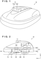
- FIG. 1 is an external view of an autonomous work machine capable of autonomously traveling according to an embodiment of the present invention.
- a moving direction vehicle length direction
- a lateral direction vehicle width direction
- a vertical direction orthogonal to the moving direction and the lateral direction in a side view of the autonomous work machine are respectively defined as a front-and-rear direction, a left-and-right direction, and an up-and-down direction, and the configuration of each part will be described in accordance with the above definition.
- reference numeral 10 denotes an autonomous work machine (hereinafter referred to as a "work vehicle”).
- the work vehicle 10 functions as a lawn mower that autonomously travels.
- the lawn mower is merely an example, and the present invention is also applicable to other types of work machines.
- the work vehicle 10 includes a camera unit 11 including a plurality of cameras (a first camera 11a and a second camera 11b), and calculates and acquires distance information between an object existing forward and the work vehicle 10 using images captured by the first camera 11a and the second camera 11b having parallax. Then, the operation of the work vehicle 10 is controlled based on the captured image and the object recognition model held in advance.
- FIG. 2 is a diagram illustrating the work vehicle 10 observed in the lateral direction (vehicle width direction).
- the work vehicle 10 includes the camera unit 11, a vehicle body 12, a stay 13, front wheels 14, rear wheels 16, a blade 20, a work motor 22, a motor holding member 23, a blade-height adjustment motor 100, and a translation mechanism 101.
- the work vehicle 10 further includes a travel motor 26, a group of various sensors S, an electronic control unit (ECU) 44, a charging unit 30, a battery 32, a charging terminal 34, and a communication unit 35.
- ECU electronice control unit
- the vehicle body 12 of the work vehicle 10 includes a chassis 12a, and a frame 12b attached to the chassis 12a.
- the front wheels 14 include one left wheel and one right wheel each having a smaller diameter and fixed to the front of the chassis 12a through the stay 13 in the front-and-rear direction.
- the rear wheels 16 include one left wheel and one right wheel each having a larger diameter and attached to the rear of the chassis 12a.
- the blade 20 is a rotary blade for a lawn mowing work, and is attached near the central position of the chassis 12a.
- the work motor 22 is an electric motor disposed above the blade 20.
- the blade 20 is connected with the work motor 22, and is rotatably driven by the work motor 22.
- the motor holding member 23 holds the work motor 22.
- the motor holding member 23 is restricted in rotation with respect to the chassis 12a, and is allowed to move in the up-and-down direction by, for example, the combination of a guide rail and a slider movable up and down while being guided by the guide rail.
- the blade-height adjustment motor 100 is a motor for adjusting the height in the up-and-down direction of the blade 20 to the ground surface GR.
- the translation mechanism 101 is connected to the blade-height adjustment motor 100, and is a mechanism for converting rotation of the blade-height adjustment motor 100 into translation in the up-and-down direction.
- the translation mechanism 101 is also connected with the motor holding member 23 that holds the work motor 22.
- the rotation of the blade-height adjustment motor 100 is converted into the translation (movement in the up-and-down direction) by the translation mechanism 101, and the translation is transmitted to the motor holding member 23. Due to the translation (movement in the up-and-down direction) of the motor holding member 23, the work motor 22 held by the motor holding member 23 also is translated (moves in the up-and-down direction). Due to the movement in the up-and-down direction of the work motor 22, the height of the blade 20 with respect to the ground surface GR is adjustable.
- the travel motor 26 is two electric motors (prime movers) attached to the chassis 12a of the work vehicle 10.
- the two electric motors are connected one-to-one to the left and right rear wheels 16.
- the charging terminal 34 is a charging terminal provided at a front end position in the front-and-rear direction of the frame 12b, and is connected with a corresponding terminal of a charging station (for example, a charging station 300 that will be described later with reference to FIG. 3 ) to receive electric power supplied from the charging station.
- the charging terminal 34 is connected with the charging unit 30 through wiring, and the charging unit 30 is connected with the battery 32.
- the work motor 22, the travel motor 26, and the blade-height adjustment motor 100 are connected to the battery 32, and are supplied with power from the battery 32.
- An ECU 44 is an electronic control unit including a microcomputer formed on a circuit board and controls the operation of the work vehicle 10. The details of the ECU 44 will be described later.
- the communication unit 35 can transmit and receive information to and from an external device (for example, a charging station that will be described later, a communication terminal possessed by a user, a remote controller for operating the work vehicle 10, or the like) connected with the work vehicle 10 in a wired or wireless manner.
- an external device for example, a charging station that will be described later, a communication terminal possessed by a user, a remote controller for operating the work vehicle 10, or the like
- FIG. 3 is a diagram illustrating a configuration example of a control system according to an embodiment of the present invention.
- a control system 1 includes the work vehicle 10 and the charging station 300. Note that a remote controller for operating a communication terminal possessed by a user that will be described later or the work vehicle 10 may be further included.
- the ECU 44 included in the work vehicle 10 includes a CPU 44a, an I/O 44b, and a memory 44c.
- the I/O 44b inputs and outputs various types of information.
- the memory 44c is a read-only memory (ROM), an electrically erasable programmable read-only memory (EEPROM), a random access memory (RAM), or the like.
- the memory 44c stores a captured image, a work schedule of the work vehicle 10, map information on a work area, various programs for controlling the operation of the work vehicle 10, and the like.
- the ECU 44 reads and executes a program stored in the memory 44c.
- the ECU 44 is connected with the group of various sensors S.
- the sensor group S includes an orientation sensor 46, a GPS sensor 48, a wheel speed sensor 50, an angular speed sensor 52, an acceleration sensor 54, a current sensor 62, and a blade height sensor 64.
- the orientation sensor 46 and the GPS sensor 48 are sensors for acquiring information on the orientation and position of the work vehicle 10.
- the orientation sensor 46 detects the orientation in accordance with terrestrial magnetism.
- the GPS sensor 48 receives a radio wave from a GPS satellite and detects information indicating a current position (latitude and longitude) of the work vehicle 10.
- odometry and an inertial measurement unit (IMU) may be provided.
- the wheel speed sensor 50, the angular speed sensor 52, and the acceleration sensor 54 are sensors for acquiring information regarding a moving state of the work vehicle 10.
- the wheel speed sensor 50 detects the wheel speeds of the left and right rear wheels 16.
- the angular speed sensor 52 detects an angular speed around an axis in the up-and-down direction (z axis in the vertical direction) of the gravity center position of the work vehicle 10.
- the acceleration sensor 54 detects accelerations in the 3 orthogonally triaxial directions of x, y, and z axes acting on the autonomous work vehicle 10.
- the current sensor 62 detects the current consumption (amount of power consumption) of the battery 32.
- the detection result of the current consumption (amount of power consumption) is stored in the memory 44c of the ECU 44.
- the ECU 44 performs returning control for causing the autonomous work vehicle 10 to return to the charging station 300 for charging. Note that a daily work schedule may be stored in the memory 44c, and the returning control may be performed in response to completion of work to be performed on that day.
- the blade height sensor 64 detects a height of the blade 20 with respect to a ground surface GR.
- the detection result of the blade height sensor 64 is output to the ECU 44.
- the blade-height adjustment motor 100 is driven and the blade 20 moves up and down in the up-and-down direction to adjust the height from the ground surface GR.
- Outputs from the group of various sensors S are input into the ECU 44 through the I/O 44b.
- the ECU 44 supplies power from the battery 32 to the travel motor 26, the work motor 22, and the height adjustment motor 100.
- the ECU 44 controls the traveling of the work vehicle 10 by outputting a control value via the I/O 44b and controlling the travel motor 26.
- the height of the blade 20 is adjusted by outputting a control value through the I/O 44b and controlling the height adjustment motor 100.
- the rotation of the blade 20 is controlled by outputting a control value through the I/O 44b to control the work motor 22.
- the I/O 44b can function as a communication interface and can be connected to another device in a wired or wireless manner via a network 150.
- the charging station 300 functions as a charging device for charging a battery (battery 32) of the work vehicle 10.
- the work vehicle 10 is installed in the work area, and can return to the charging station 300 and perform charging by connecting the charging terminal 34 to the charging station 300.
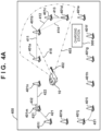
- a virtual line setting method will be described with reference to FIG. 4A .
- a virtual line is an imaginary line connecting markers arranged to define the work area.
- reference numeral 400 denotes a region (for example, the entire site owned by a user) including the work area (for example, a garden) where the work vehicle 10 performs work.
- Reference numerals 401a to 401n denote markers according to the present embodiment. An area surrounded by these markers 401a to 401n is a work area. The work vehicle 10 performs work so as not to deviate from this work area by performing control so as not to deviate to a region beyond the virtual line.
- the work area may be defined by partitioning the entire site using an existing area wire of a type that is embedded in the ground, and disposing markers in a part of the site to provide a non-entry area. That is, the present invention can also be applied to a case where a work area is defined by combining an existing area wire and a marker.
- Reference numeral 402 denotes a traveling direction of the work vehicle 10
- reference numeral 403 denotes a range (for example, an angle of view range) that the work vehicle 10 can recognize by the camera unit 11.
- four markers 401a to 401d are included in the recognizable range.
- the work vehicle 10 sets a virtual line (virtual wire) between two adjacent markers.
- a virtual line 411 is set between the marker 401a and the marker 401b
- a virtual line 412 is set between the marker 401b and the marker 401c
- a virtual line 413 is set between the marker 401c and the marker 401d.
- a virtual line is not set.
- the virtual line is not limited to a straight line.
- a smooth curve may be set like a virtual line 431 set between the marker 401i and the marker 401j.
- Whether two markers are adjacent markers can be determined based on the distance between the markers in the case where it is assumed that the markers are arranged at predetermined distance intervals.
- a predetermined distance range for example, 2.5 m to 3.5 m
- the markers are adjacent markers
- the distance is out of the predetermined distance range it may be determined that the markers are not adjacent markers.
- the line is not set as a virtual line. As a result, it is possible to prevent the work from not being performed in the region of a triangle obtained by connecting the marker 401b, the marker 401c, and the marker 401d.
- the determination method 1 among the plurality of markers, two markers whose distance between the markers is within the predetermined distance range are specified as adjacent markers.
- the predetermined distance range do not have to have an upper limit value or a lower limit value, for example, like 2.5 m or more, 3 m or more, 3 m or less, or 3.5 m or less.
- the method for determining whether two markers are adjacent markers is not limited to a method using the distance between the markers.
- a marker such as the marker 401m in FIG. 4A , including an indicator (For example, 431 and 432) for indicating a direction in which an adjacent marker is present
- each indicator may be detected, and a nearby marker present in the direction indicated by the indicator 431 or 432 may be determined to be an adjacent marker.
- a virtual line 421 is set between the marker 401l and the marker 401m existing in the direction indicated by the indicator 431, and a virtual line 422 is set between the marker 401n and the marker 401n.
- each marker may be configured to include indicators indicating at least two directions similarly to 401m.
- each marker includes an indicator indicating the direction in which an adjacent marker exists, and a second marker existing in the direction indicated by the indicator of a first marker can be specified as an adjacent marker.
- the marker existing closest to the first marker may be specified as the adjacent marker.
- a marker in a direction indicated by the indicator and within a predetermined distance range for example, 2.5 m to 3.5 m
- the direction indicated by the indicator may be freely changed by the user.
- the direction of the indicator may be adjustable using a rotation mechanism or the like.
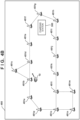
- FIG. 4B is an explanatory diagram of a method of determining an adjacent marker in a work area in which an equilateral triangular or square region is formed.
- Reference numeral 450 denotes a region (for example, the entire site owned by a user) including the work area (for example, a garden) where the work vehicle 10 performs work.
- Reference numerals 451a to 451p denote markers according to the present embodiment. An area surrounded by these markers 451a to 451p is a work area. The work vehicle 10 performs work so as not to deviate from the work area.
- the markers 451a to 451p are arranged at predetermined distance (for example, 3 m) intervals.
- an equilateral triangular region is formed by three markers of the marker 451b, the marker 451c, and the marker 451d.
- a square region is formed by four markers of the marker 451l, the marker 451m, the marker 451n, and the marker 4510. If there are such regions, when the determination method 1 is used, the work vehicle 10 cannot move to a region behind the virtual line connecting the marker 451b and the marker 451c and the virtual line connecting the marker 451l and the marker 451c, so that the work cannot be performed in these regions.
- the two markers 451b and the marker 451d are detected, and the other marker 451c is further detected behind the two markers. Therefore, it is determined that the two markers 451b and 451d are not adjacent markers.
- two markers of the marker 451l and the marker 4510 are detected, and the other markers 451m and 451n are further detected behind the two markers. Therefore, it is determined that the two markers 451l and 4510 are not adjacent markers.
- the determination method 3 when another marker is present in a region behind a line connecting two markers, it is specified that the two markers are not adjacent markers.
- the determination method 3 when the determination method 3 is applied, in the case where another marker at a position far away from the two markers is detected, there is a possibility of erroneous entry to the back region. Therefore, a configuration in which movement to the back region is only possible when the distance to the other marker is calculated and the calculated distance is equal to or less than a predetermined distance (for example, 4 m), or when it is determined that the other marker is a marker adjacent to either one of the two markers on the front side. As a result, it is possible to suppress entry into a region that should not be originally entered.
- a predetermined distance for example, 4 m
- a user 462 Before starting work by the work vehicle 10, a user 462 directly controls the work vehicle 10 by operating a remote controller 463, and moves the work vehicle 10 one lap along each marker. An operation signal from the remote controller 463 is received via the communication unit 35 of the work vehicle 10.
- the work vehicle 10 includes a GPS sensor 48, and stores a trajectory obtained by sequentially tracing each marker according to the operation signal of the remote controller 463 as trajectory information of the work area.
- a trajectory information of the work area can be grasped before the start of the work, it is possible to determine whether or not the two markers are adjacent markers, by determining that markers not following the trajectory are not adjacent markers after the start of the work.
- the trajectory information of the work vehicle 10 is acquired by causing the work vehicle 10 to travel along each of the arranged markers.
- two markers matching the trajectory information among the plurality of markers can be specified as adjacent markers.
- FIG. 4D is a diagram illustrating an example of drawing something on a map related to a work area displayed on a communication terminal held by a user.
- Reference numeral 470 denotes a communication terminal of the user, which is, for example, a tablet or a smartphone.
- Reference numeral 471 denotes a hand of the user.
- Reference numeral 472 represents map information on the work area displayed on a display screen of the communication terminal 470. In the illustrated example, a map of a site including a home and a garden of the user as viewed from above is displayed.
- Reference numeral 473 denotes a roof of the user's home, and reference numeral 474 denotes a tree space in a site of the user's home.
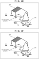
- FIG. 4E is an external view of a part of the site including the user's home corresponding to the map information of FIG. 4D .
- reference numeral 475 denotes a boundary traced on the map by the user using a finger of the hand 471.
- reference numeral 476 indicates a boundary traced around the tree space by the user using the finger of hand 471.
- a tree spaces 474 is an island excluded from the work area. Note that the boundary may be designated by connecting positions pointed by a finger instead of tracing using the finger.
- the boundary of the work area is designated on a map displayed on the communication terminal 470, and the designated boundary information (information indicating the position of a boundary line) is transmitted to the work vehicle 10.
- the work vehicle 10 can recognize its self-position and orientation using the GPS sensor 48 and the orientation sensor 46, and determine whether or not two detected markers are adjacent markers using the self-position and orientation and the boundary information.
- the work vehicle 10 can determine that a marker 481 and a marker 482 are not adjacent markers from the acquired boundary information.
- the self-position and orientation may be recognized by using, in addition to or instead of the GPS sensor 48 and the orientation sensor 46, an odometry and an inertial measurement unit (IMU).
- IMU inertial measurement unit
- the method of tracing the boundary is not limited to the method in which the user traces the boundary using the finger of the hand 471.
- the user may sequentially point out a plurality of positions of markers on the map along the boundary using the finger of the hand 471 to acquire marker arrangement information as the boundary information.
- the boundary information may be transmitted from the communication terminal 471 to the work vehicle 10.
- the work vehicle 10 can determine that the marker 481 and the marker 482 are not adjacent markers from the boundary information (marker arrangement information).
- the boundary information (for example, arrangement information of a plurality of markers arranged at the boundary of the work area (position information designated by pointing) or information of a boundary line (line traced with a finger) indicating the boundary of the work area) of the work area designated on the map including the work area is acquired.
- two markers matching the boundary information among the plurality of markers can be specified as adjacent markers.
- FIG. 4F illustrates an example of a method using two types of markers.
- Different types For example, different colors, different shapes, and the like
- markers are respectively used for each marker arranged on the boundary of the work area and each marker arranged around the tree space 474 which is an island excluded from the work area.
- the work vehicle 10 can discriminate different types of markers from the features of the markers extracted from the captured image, and the work vehicle 10 can determine that a marker 483 and a marker 484 are not adjacent markers from the captured image.
- the marker is not limited to two types of markers, and in a case where there are a plurality of islands, different types of markers may be used for respective islands. Therefore, the present invention is also applicable to a case where three or more types of markers are used.
- first type markers defining the outer edge of the work area and a plurality of second type markers defining the internal region (island) enclosed by the outer edge and excluded from the work area are used. This allows the first type markers and the second type markers to be identified as not being adjacent markers.
- the marker 491b, the marker 491c, and the marker 491d form an equilateral triangle shape
- the marker 491c, the marker 491d, and the marker 491e also form an equilateral triangle shape.
- a case where only the markers 491a to 491e are arranged in such a complicated shape will be considered.
- the marker 491e is detected at the back, so that the work vehicle can travel in a direction approaching the marker 491e at the back beyond the boundary of the work area connecting the marker 491c and the marker 491d.
- the markers 492a to 492f are further arranged at places having complicated shapes. Accordingly, since the work vehicle 10 further detects the marker 492c and the marker 492d on the line connecting the marker 491c and the marker 491d, it is possible to determine that the two markers (the marker 491c and the marker 491d) are adjacent markers. Therefore, it is possible to prevent the work vehicle 10 from deviating to the back region beyond the boundary of the work area connecting the marker 491c and the marker 491d.
- the two markers 492c and 492d are detected is has been described for the illustrated example, it may be determined that the two markers (the marker 491c and the marker 491d) are adjacent markers when either the marker 492c or the marker 492d is detected on the line connecting the marker 491c and the marker 491d.
- the plurality of first type markers arranged at the first distance intervals and the plurality of second type markers arranged at the second distance intervals shorter than the first distance intervals are used. Accordingly, when one or more second type markers are present between two first type markers among a plurality of first type markers, the two first type markers can be identified as adjacent markers.
- the work vehicle 10 according to the present embodiment sets a virtual line between markers and performs control so that the work vehicle 10 does not deviate to a region beyond the virtual line.
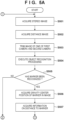
- step S501 the CPU 44a acquires a stereo image captured by the camera unit 11.
- step S502 the CPU 44a acquires a distance image based on the stereo image.
- step S503 the CPU 44a trims an image of one of the first camera 11a and the second camera 11b constituting the camera unit 11. In the present embodiment, an image of the second camera 11b is used.
- step S504 the CPU 44a executes object recognition processing using the trimmed image.
- Features of objects including persons and markers are learned in advance by machine learning, and an object is recognized by comparison with the learning result.
- step S505 the CPU 44a determines whether or not a marker has been recognized as a result of the object recognition processing in step S504. In the case where it is determined that a marker has been recognized, the process proceeds to step S506. In the case where it is determined that a marker has not been recognized, the process proceeds to step S517.
- step S506 the CPU 44a acquires the gravity center position of the marker in the image.
- a specific position of the marker is specified as the gravity center position based on information of the gravity center position of the marker held in advance.
- the gravity center position is merely an example, and is not limited to the gravity center position.
- the position may be a top position of the marker, or may be a ground contact position where the marker and the ground are in contact with each other.
- step S507 the CPU 44a acquires information of the distance from the work vehicle 10 to the gravity center position of the marker as marker information using the distance image acquired in step S502.
- step S508 the CPU 44a determines whether or not a plurality of markers have been recognized in step S505. In the case where it is determined that a plurality of markers have been recognized, the process proceeds to step S509. In the case where only a single marker has been recognized, the process proceeds to step S515.
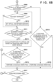
- step S509 the CPU 44a determines whether or not two markers included in the plurality of markers are adjacent markers. In the present embodiment, whether or not the distance between the two markers is within a predetermined distance range is determined, and when the distance is within the predetermined distance range, it is determined that the markers are adjacent markers. In the present embodiment, it is assumed that the markers are installed at intervals of 3 m, but the markers are not necessarily arranged at equal intervals of 3 m, and there is a possibility that some deviation occurs. Therefore, it is determined that the markers are adjacent markers if the markers are within the predetermined distance range, for example, in a range of 2.5 m to 3.5 m. In the case where it is determined that the markers are adjacent markers, the process proceeds to step S510. In contrast, in the case where it is determined that the markers are not adjacent markers, the process proceeds to step S511. As a method of determining whether or not the markers, other determination methods described with reference to FIGS. 4A to 4G may be used.
- step S510 the CPU 44a sets a virtual line between the two markers determined to be adjacent markers.
- step S511 the CPU 44a determines whether or not the determination has been completed for all combinations of two markers among the plurality of markers. When the determination is completed for all the combinations, the process proceeds to step S512. In contrast, in the case where there remains a combination for which the determination has not been performed yet, the process returns to step S509, and the determination is performed on a new combination of two markers.
- step S512 the CPU 44a calculates the distance from the work vehicle 10 to a virtual line located ahead of the work vehicle 10 in the traveling direction based on the traveling direction of the work vehicle 10 and the virtual line located ahead in the traveling direction. In the example of FIG. 4A , the distance to an intersection with the virtual line 411 located ahead in the traveling direction 402 is calculated.
- a point O is a current position of the work vehicle 10.
- a point A corresponds to the marker 401a in FIG. 4A
- a point B corresponds to the marker 401b in FIG. 4A .
- X is the length of a line OC.
- the length of a line OA and the length of a line OB can be obtained from the distance image.
- AD OAsin ⁇
- BE OBsin ⁇
- CD OC - OAcos ⁇
- CE OBcos ⁇ - OC hold, and therefore a distance X to the point C can be obtained by AD :
- BE CD :
- step S513 the CPU 44a determines whether or not the distance from the work vehicle 10 to the virtual line located ahead of the work vehicle 10 in the traveling direction is equal to or less than a threshold value (for example, 0.1 m). When it is determined that the distance is equal to or less than the threshold, the process proceeds to S514. In contrast, in the case where the distance is larger than the threshold value, the process proceeds to step S517.
- a threshold value for example, 0.1 m
- step S514 the CPU 44a executes an avoidance operation based on the virtual line. Specifically, when the work vehicle 10 approaches a threshold (for example, 0.1 m) from the virtual line, the work vehicle 10 stops, moves backward, or turns. Accordingly, it is possible to prevent the work vehicle 10 from deviating to a region beyond the virtual line. For example, the work vehicle 10 stops, moves backward, or turns the work vehicle 10 when the distance from the work vehicle 10 to the virtual line 415 becomes equal to or less than the threshold so as not to deviate to the back region beyond the intersection position of the line 415 extending in the traveling direction 415 and the virtual line 411 existing in the traveling direction 415 illustrated in FIG. 4A .
- a threshold for example, 0.1 m
- the work vehicle 10 can perform work without deviating from the work area.
- the turning is to change the traveling direction of the work vehicle 10, and includes moving along a parabolic trajectory when the site is viewed from above, rotating on the spot after stopping at a certain point to change the traveling direction, and going around so as not to enter the region defined by the virtual line.
- control for lowering the traveling speed of the work vehicle 10 heading for the virtual line 415 may be further performed.
- another threshold value for example, 1.5 m
- control for lowering the traveling speed of the work vehicle 10 heading for the virtual line 415 may be further performed.
- step S515 the CPU 44a determines whether or not the distance from the work vehicle 10 to the marker is equal to or less than a threshold.
- the threshold here is, for example, 0.5 m, but is not limited to this value.
- the process proceeds to S516.
- the process proceeds to step S517.
- step S516 the CPU 44a executes the avoidance operation. Specifically, when the work vehicle 10 stops, moves backward, or turns when reaching a threshold distance (for example, 0.5 m) from a marker. Since only one marker is detected, the avoidance operation is performed independently of the virtual line. Thereafter, the process proceeds to step S517.
- a threshold distance for example, 0.5 m
- step S517 the CPU 44a determines whether to end the series of processing. For example, there are a case where the remaining battery charge becomes equal to or lower than a threshold and it is necessary to return to the charging station 300, a case where a predetermined time has elapsed from the start of work, and a case where work in the work area has been completed (for example, the lawn in the work area has been mowed). This also applies to a case where the user operates the power source of the work vehicle 10 to be turned off. In the case where it is determined not to end the series of processing, the process returns to step S501. In contrast, in the case where it is determined to end the series of processing, the processing of FIGS. 5A and 5B is ended.
- the present embodiment two markers are detected, and a virtual line is set between the markers. Then, the avoidance operation is executed so that the work vehicle does not deviate to the back region beyond the virtual line.
- the virtual line virtual wire
- the virtual line virtual wire
- an existing area wire and a marker may be combined to define the work area, and in this case, the area wire does not have to be provided for some regions, so that the cost can be reduced.
- the markers can be freely arranged, the shape of the work area can be flexibly changed. For example, in the case where the user himself/herself works in a part of a garden, there is a case where the work vehicle is not desired to enter the area. In this case, by defining the region so as to be surrounded by markers, it is possible to easily create an area where the work vehicle does not temporarily enter.
- the CPU 44a sets a travel route for the work vehicle 10 to travel according to the set travel route. At that time, the travel route is set such that the virtual line does not exist on the travel route. Accordingly, it is possible to prevent traveling beyond the virtual line and deviating.
- markers on the left and right of the line along the traveling direction may be set as processing targets based on the traveling direction of the work vehicle 10.
- markers on the left and right of the line 415 along the traveling direction 415 instead of processing all the combinations (6 combinations) of the four markers 401a to 401d.
- three combinations of the marker 401a and the marker 401b, the marker 401a and the marker 401c, and the marker 401a and the marker 401d may be set as processing targets, and three combinations of the marker 401b and the marker 401c, the marker 401b and the marker 401d, and the marker 401c and the marker 401d may be excluded from the processing targets. This makes it possible to speed up the processing.
- step S513 when the distance from the work vehicle 10 to the virtual line is larger than the threshold in step S513, the process returns to step S501 through step S517, and the stereo image is acquired again.
- control instead of necessarily returning to step S501 and re-capturing images, control may be performed such that the timing at which the distance from the work vehicle 10 to the virtual line becomes equal to or less than the threshold is estimated on the basis of the traveling speed of the work vehicle 10, and the avoidance operation is executed when that timing arrives.
- a distance from a certain point to the virtual line is calculated, and thereafter, a moving distance from the point is constantly measured by odometry, an inertial measurement unit (IMU), or the like. Then, the operation of the work vehicle 10 may be controlled based on the calculated distance and the moving distance being measured. For example, the avoidance operation may be executed in response to the moving distance being measured reaching the "distance from the point to the virtual line".
- IMU inertial measurement unit
- steps S512 and S513 an example in which the avoidance operation is controlled on the basis of the distance between the work vehicle 10 and the virtual line has been described, but it is not limited to the distance.
- a time required for the work vehicle 10 to reach the virtual line 411 may be calculated, and whether or not the work vehicle 10 has reached the virtual line may be determined on the basis of the calculated time.
- the time may be calculated based on the traveling speed of the work vehicle 10 and the distance from the work vehicle 10 to the virtual line 411.
- the avoidance operation may be controlled to be executed when the difference between the time and the elapsed time is equal to or less than a threshold.
- step S515 an example in which the avoidance operation is controlled on the basis of the distance between the work vehicle 10 and a marker has been described, but it is not limited to the distance.
- a time required for the work vehicle 10 to reach the marker may be calculated, and whether or not the work vehicle 10 has reached the marker may be determined on the basis of the calculated time.
- control may be performed in parallel with repeating the processing by returning to step S501, such that the avoidance operation is separately executed when the timing at which the distance from the work vehicle 10 to the virtual line becomes equal to or less than the threshold arrives.
- an example has been described in which information of the distance to a detected marker is acquired as marker information, and the avoidance operation is performed by calculating the distance from the work vehicle to the virtual line and the time until the work vehicle reaches the virtual line are calculated using the distance information.
- marker position information indicating position coordinates of a marker is acquired as marker information
- the avoidance operation is performed by calculating a distance from the work vehicle to the virtual line and a time until the work vehicle reaches the virtual line by using the marker position information and self-position information and orientation information of the work vehicle.
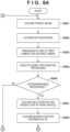
- the work vehicle 10 according to the present embodiment sets a virtual line between markers and performs control so that the work vehicle 10 does not deviate to a region beyond the virtual line. Steps of performing the same processes as those in the flowcharts of FIGS. 5A and 5B are denoted by the same reference numerals. Hereinafter, differences from FIGS. 5A and 5B will be mainly described.
- step S801 the CPU 44a acquires information on the self-position and orientation using the GPS sensor 48 and the orientation sensor 46.
- the work vehicle 10 recognizes its self-position and orientation using the GPS sensor 48 and the orientation sensor 46, and acquires, on the basis of an image having parallax (S501 and S502), information on the distance (distance image) to a marker detected from an image captured by the camera unit 11. Furthermore, an angle (for example, the angle ⁇ or the angle ⁇ in FIG. 6 ) at which the marker exists with respect to the photographing direction of the camera unit 11 is obtained from the position of the marker with respect to the image center of the captured image. Then, a direction in which the marker is present may be specified from the orientation of the work vehicle 10 and the acquired angle, and position coordinates that is ahead along the direction by a distance indicated by the acquired distance information may be acquired as the marker position information.
- an angle for example, the angle ⁇ or the angle ⁇ in FIG. 6
- step S803 the CPU 44a determines whether or not two markers included in the plurality of markers are adjacent markers. Also in the present embodiment, the determination method is the same as that in the first embodiment, and thus detailed description thereof is omitted.
- step S804 the CPU 44a calculates the distance from the work vehicle 10 to a virtual line located ahead of the work vehicle 10 in the traveling direction based on the traveling direction of the work vehicle 10 and the virtual line located ahead in the traveling direction. In the example of FIG. 4A , the distance to an intersection with the virtual line 411 located ahead in the traveling direction 402 is calculated.
- a point O is a current position of the work vehicle 10.
- a point A corresponds to the marker 401a in FIG. 4A
- a point B corresponds to the marker 401b in FIG. 4A .
- X is the length of a line OC.
- the position coordinates of the point A, the position coordinates of the point B, and the position coordinates (self-position) of the point O are known, the length of the line OA and the length of the line OB can be obtained from these.
- the distance from the work vehicle 10 to the virtual line 411 located ahead in the traveling direction of the work vehicle 10 is calculated by a procedure similar to the procedure described in the first embodiment.
- marker position information indicating position coordinates of a marker is acquired as marker information, and the avoidance operation is performed by calculating a distance from the work vehicle to the virtual line and a time until the work vehicle reaches the virtual line by using the marker position information and self-position information and orientation information of the work vehicle.
- the operation of the work vehicle can be controlled using the marker position information indicating the position coordinates of the marker and the self-position and orientation of the work vehicle.
- map information including position information of markers arranged to define a work area is generated and presented to a user.
- the work vehicle 10 acquires information on the distance to the detected marker from an image captured by the camera unit 11, while acquiring information on its self-position and orientation using the GPS sensor 48 and the orientation sensor 46.
- the distance to the marker can be acquired on the basis of an image having parallax.
- an angle (for example, the angle ⁇ or the angle ⁇ in FIG. 6 ) at which the marker exists with respect to the photographing direction of the camera unit 11 is obtained from the position of the marker with respect to the image center of the captured image as illustrated in FIG. 7 .
- a direction in which the marker is present may be specified from the orientation of the work vehicle 10 and the acquired angle, and position coordinates that is ahead along the direction by a distance indicated by the acquired distance information is acquired as the marker position information.
- the work vehicle calculates position information (position coordinates) of the marker by using information on the self-position and orientation, information on the distance to the marker, and a direction in which the marker exists. Then, the calculated position information of the marker is plotted on the map.
- map information including position information of markers arranged to define a work area can be generated.
- FIG. 9 is an example of a map on which position information of markers is plotted.
- Reference numeral 901 denoted a map, and the map is defined as a grid area divided in a grid pattern.
- Reference numerals 901a to 901w are each position information of a plotted marker.
- the work vehicle 10 generates such map information and stores the map information as a map database while performing work or traveling before starting work.
- the generated map information may be presented to the user.
- the presentation may be performed by displaying on the display unit.
- the work vehicle 10 may transmit map information to a communication terminal (for example, a tablet, a smartphone, or the like) possessed by the user and present the map information on a display screen of the communication terminal.
- a communication terminal for example, a tablet, a smartphone, or the like
- an example map information including marker positions arranged to define a work area is generated and presented to the user.
- the user can acquire the map information on manually arranged markers. Therefore, it is also possible to manually adjust the arrangement positions of the markers later to redefine a more appropriate work area.
- processing of the present embodiment may be performed in parallel with the first embodiment and the second embodiment, or may be performed independently of these.
- at least one of the information of the virtual line acquired by the processing of the first embodiment or the second embodiment and the position information of the marker acquired by the processing of the third embodiment may be reflected in the map information and presented to the user.
- the lawn mower has been described as an example of the autonomous work machine, but the autonomous work machine is not limited to the lawn mower.
- the present invention can also be applied to other types of autonomous work machines such as an autonomous snow removing machines, golf ball collectors, outboard motors, and the like.
- An autonomous work machine (for example, 10) of the embodiments described above is an autonomous work machine that works in a work area.
- the autonomous work machine includes a detection means (for example, 11 and 44a) that detects a plurality of markers (for example, 401a to 401n) arranged to define the work area, a specifying means (for example, 44a) that specifies marker information based on a detection result of the detection means, a setting means (for example, 44a) that sets a virtual line (for example, 411, 412, and 413) connecting the plurality of markers based on the marker information specified by the specifying means, and a control means (for example, 44a) that controls the autonomous work machine such that the autonomous work machine does not deviate to a region beyond the virtual line set by the setting means.
- the work machine can be controlled using the same type of marker.
- control means calculates the time based on a speed of the autonomous work machine and a distance from the autonomous work machine to the virtual line.
- the avoidance operation can be performed before the time required to reach the virtual line is reached.
- deviation can be prevented without using an IMU or a GPS sensor for recognizing the self-position.
- a measuring means for example, IMU or odometry that measures a moving distance of the autonomous work machine.
- the control means calculates a distance from the autonomous work machine to the virtual line based on the marker information, and controls the autonomous work machine based on the calculated distance and the moving distance from a position of the autonomous work machine where the distance has been calculated.
- the autonomous work machine can be controlled.
- the marker information includes distance information indicating a distance from the autonomous work machine to a marker, and the setting means sets the virtual line based on the distance information.
- the virtual line since a virtual line is set using distance information indicating the distance to a marker, the virtual line can be set even if the position information of the marker is not known.
- the marker information includes marker position information indicating a position coordinate of a marker
- the setting means sets the virtual line based on the marker position information.
- the virtual line can be set without additionally acquiring information on the distance to a marker.
- a storage means (for example, 44c) that stores feature information of a marker is further provided, and the specifying means specifies the marker information based on the feature information of a marker stored in the storage means and a feature of a marker detected by the detection means.
- the control means stops, moves backward, or turns the autonomous work machine in a case where a distance from the autonomous work machine to the virtual line becomes equal to or less than a first threshold.
- an adjacent marker specifying means (for example, 44a) that specifies two markers as adjacent markers among the plurality of markers detected by the detection means is further provided, and the control means sets a virtual line between the two markers specified as the adjacent markers by the adjacent marker specifying means.
- the adjacent marker specifying means specifies, as the adjacent markers, two markers having a distance therebetween within a predetermined distance range among the plurality of markers.
- the adjacent marker specifying means specifies that the two markers are not the adjacent markers.
- an acquisition means that acquires boundary information (for example, 475 and 476) of the work area designated on a map including the work area is further provided.
- the adjacent marker specifying means specifies, as the adjacent markers, two markers matching the boundary information among the plurality of markers.
- the boundary information is arrangement information (for example, 476) of a plurality of markers arranged at a boundary of the work area, or information (for example, 475) of a boundary line indicating a boundary of the work area.
- the plurality of markers include a plurality of first type of markers (for example, 483) defining an outer edge of the work area, and a plurality of second type of markers (for example, 484) defining an inner region that is included in an inside of the outer edge and excluded from the work area.
- the adjacent marker specifying means specifies the first type of markers and the second type of markers as not being the adjacent markers.
- the plurality of markers include a plurality of first type of markers (for example, 491a to 491e) arranged at first distance intervals, and a plurality of second type of markers (for example, 492a to 492f) arranged at second distance intervals smaller than the first distance intervals.
- the adjacent marker specifying means specifies the two of the first type of markers as the adjacent markers.
- the travel route is a travel route for returning to a station.
- a position specifying means (for example, 48) that specifies a current position of the autonomous work machine is further provided.
- the control means controls the autonomous work machine based on information on the virtual line and the current position of the autonomous work machine specified by the position specifying means.
- control means reflects at least one of the marker position information (for example, 901a to 901w) and the information on the virtual line on the map information (for example, 900) of the work area.
- control means presents, to a user, the map information on which at least one of the marker position information and the information on the virtual line is reflected.
- the user can recognize the generated map information.
- the control means transmits, to a communication terminal (for example, 470) of a user, the map information on which at least one of the marker position information and the information on the virtual line is reflected.
- a control method for the autonomous work machine (for example, 10) of the embodiments described above is a control method for an autonomous work machine that works in a work area.
- the control method for an autonomous work machine includes a detection step for detecting a plurality of markers arranged to define the work area, a specifying step for specifying marker information based on a detection result of the detection step, a setting step for setting a virtual line connecting the plurality of markers based on the marker information specified in the specifying step, and a control step for controlling the autonomous work machine such that the autonomous work machine does not deviate to a region beyond the virtual line set in the setting step.
- the work machine can be controlled using the same type of marker.
- a program according to the embodiment described above is a program for causing a computer to function as the autonomous work machine according to the embodiments described above.
- the autonomous work machine according to the present invention can be realized by a computer.
Landscapes
- Engineering & Computer Science (AREA)
- Physics & Mathematics (AREA)
- Radar, Positioning & Navigation (AREA)
- Remote Sensing (AREA)
- Aviation & Aerospace Engineering (AREA)
- General Physics & Mathematics (AREA)
- Automation & Control Theory (AREA)
- Computer Vision & Pattern Recognition (AREA)
- Electromagnetism (AREA)
- Multimedia (AREA)
- Control Of Position, Course, Altitude, Or Attitude Of Moving Bodies (AREA)
Claims (19)
- Eine autonome Arbeitsmaschine zum Arbeiten in einem Arbeitsbereich, wobei die autonome Arbeitsmaschine aufweist:eine Erfassungseinrichtung (11, 44a), die so ausgebildet ist, dass sie eine Mehrzahl an Markierungen (401a bis 401n, 451a bis 451p, 461a bis 461m) erfasst, die so angeordnet sind, dass sie den Arbeitsbereich definieren;eine Spezifizierungseinrichtung (44a), die so ausgebildet ist, dass sie auf der Grundlage eines Erfassungsergebnisses der Erfassungseinrichtung (11, 44a) Markierungsinformation spezifiziert;eine Festlegungseinrichtung (44a), die so ausgebildet ist, dass sie eine virtuelle Linie (411, 412, 413, 414, 431, 421, 422) festlegt, welche die Mehrzahl an Markierungen (401a bis 401n, 451a bis 451p, 461a bis 461m) auf der Grundlage der von der Spezifizierungseinrichtung (44a) spezifizierten Markierungsinformation verbindet; undeine Steuereinrichtung (44a), die so ausgebildet ist, dass sie die autonome Arbeitsmaschine so steuert, dass die autonome Arbeitsmaschine nicht in einen Bereich jenseits der durch die Festlegungseinrichtung (44a) festgelegten virtuellen Linie (411, 412, 413, 414, 421, 422) abweicht, dadurch gekennzeichnet, dassdie Steuereinrichtung (44a) so ausgebildet ist, dass sie eine Zeit berechnet, die die autonome Arbeitsmaschine benötigt, um die virtuelle Linie (411, 412, 413, 414, 421, 422) zu erreichen, und dass sie die autonome Arbeitsmaschine auf der Grundlage der berechneten Zeit steuert.
- Die autonome Arbeitsmaschine nach Anspruch 1, dadurch gekennzeichnet, dass
die Steuereinrichtung (44a) so ausgebildet ist, dass sie die Zeit auf der Grundlage einer Geschwindigkeit der autonomen Arbeitsmaschine und einer Entfernung von der autonomen Arbeitsmaschine zu der virtuellen Linie (411, 412, 413, 414, 421, 422) berechnet. - Die autonome Arbeitsmaschine nach Anspruch 1, dadurch gekennzeichnet, dass sie ferner aufweist:eine Messeinrichtung, die so ausgebildet ist, dass sie einen Bewegungsabstand der autonomen Arbeitsmaschine misst, wobeidie Steuereinrichtung (44a) so ausgebildet ist, dass sie,auf der Grundlage der Markierungsinformation, einen Abstand der autonomen Arbeitsmaschine zu der virtuellen Linie (411, 412, 413, 414) berechnet, unddie autonome Arbeitsmaschine, auf der Grundlage des berechneten Abstands und des Bewegungsabstands, ausgehend von der Position der autonomen Arbeitsmaschine, an der der Abstand berechnet wurde, steuert.
- Die autonome Arbeitsmaschine nach einem der Ansprüche 1 bis 3, dadurch gekennzeichnet, dassdie Markierungsinformation Abstandsinformation enthält, die einen Abstand der autonomen Arbeitsmaschine zu einer Markierung angibt, unddie Festlegungseinrichtung (44a) so ausgebildet ist, dass sie die virtuelle Linie (411, 412, 413, 414) auf Grundlage der Abstandsinformation festlegt; oderdie Markierungsinformation Markierungspositionsinformation enthält, die eine Positionskoordinate einer Markierung angibt, unddie Festlegungseinrichtung (44a) so ausgebildet ist, dass sie die virtuelle Linie (411, 412, 413, 414, 431, 421, 422) auf Grundlage der Markierungspositionsinformation festlegt.
- Die autonome Arbeitsmaschine nach einem der Ansprüche 1 bis 4, dadurch gekennzeichnet, dass sie ferner aufweist:eine Speichereinrichtung (44c), die so ausgebildet ist, dass sie Merkmalsinformation einer Markierung speichert, wobeidie Spezifizierungseinrichtung (44a) so ausgebildet ist, dass sie die Markierungsinformation auf Grundlage der in der Speichereinrichtung (44c) gespeicherten Merkmalsinformation einer Markierung und eines von der Erfassungseinrichtung (11, 44a) erfassten Merkmals einer Markierung spezifiziert.
- Die autonome Arbeitsmaschine nach einem der Ansprüche 1 bis 5, dadurch gekennzeichnet, dass
die Steuereinrichtung (44a) so ausgebildet ist, dass sie die autonome Arbeitsmaschine anhält, zurückfährt oder dreht, wenn ein Abstand der autonomen Arbeitsmaschine zur virtuellen Linie (411, 412, 413, 414, 431, 421, 422) einen ersten Schwellenwert erreicht oder diesen unterschreitet. - Die autonome Arbeitsmaschine nach Anspruch 6, dadurch gekennzeichnet, dass
die Steuereinrichtung (44a) so ausgebildet ist, dass sie, im Falle, dass der Abstand der autonomen Arbeitsmaschine zur virtuellen Linie (411, 412, 413, 414, 431, 421, 422) einen zweiten Schwellenwert erreicht oder diesen unterschreitet, wobei der zweite Schwellenwert größer als der erste Schwellenwert ist, die auf die virtuelle Linie (411, 412, 413, 414, 431, 421, 422) zusteuernde autonome Arbeitsmaschine verlangsamt. - Die autonome Arbeitsmaschine nach einem der Ansprüche 1 bis 7, dadurch gekennzeichnet, dass sie ferner aufweist:eine Einrichtung zum Spezifizieren benachbarter Markierungen, die so ausgebildet ist, dass sie zwei Markierungen aus der Mehrzahl der von der Erfassungseinrichtung (11, 44a) erfassten Markierungen (401a bis 401n, 451a bis 451p, 461a bis 461m) als benachbarte Markierungen spezifiziert, wobeidie Steuereinrichtung so ausgebildet ist, dass sie zwischen den beiden, von der Einrichtung zum Spezifizieren benachbarter Markierungen als benachbarte Markierungen spezifizierten Markierungen eine virtuelle Linie (411, 412, 413, 414, 431, 421, 422) festlegt.
- Die autonome Arbeitsmaschine nach Anspruch 8, dadurch gekennzeichnet, dass
die Einrichtung (44a) zum Spezifizieren benachbarter Markierungen so ausgebildet ist, dass sie als benachbarte Markierungen zwei Markierungen spezifiziert, die, unter der Mehrzahl an Markierungen, zueinander einen Abstand innerhalb eines vorbestimmten Abstandsbereichs aufweisen. - Die autonome Arbeitsmaschine nach Anspruch 8 oder 9, dadurch gekennzeichnet, dass
im Falle, dass eine andere durch die Erfassungseinrichtung (11, 44a) erfasste Markierung (451c) sich in einem Bereich jenseits einer die beiden Markierungen (451b, 451d) verbindenden Linie befindet, die Einrichtung (44a) zum Spezifizieren benachbarter Markierungen so ausgebildet ist, dass sie spezifiziert, dass die beiden Markierungen nicht die benachbarten Markierungen sind. - Die autonome Arbeitsmaschine nach Anspruch 8, dadurch gekennzeichnetdass jede Markierung einen Indikator (431, 432) aufweist, der eine Richtung anzeigt, in der sich eine benachbarte Markierung befindet, und dass die Einrichtung (44a) zum Spezifizieren benachbarter Markierungen so ausgebildet ist, dass sie als die benachbarte Markierung eine zweite Markierung (431, 432) spezifiziert, die sich in einer durch den Indikator einer ersten Markierung (401m) angezeigten Richtung befindet, oderdass die Mehrzahl an Markierungen eine Mehrzahl an Markierungen (483) eines ersten Typs aufweisen, die einen äußeren Rand des Arbeitsbereichs definieren, sowie eine Mehrzahl an Markierungen (484) eines zweiten Typs, die einen inneren Bereich definieren, der in einer Innenseite des äußeren Randes enthalten und von dem Arbeitsbereich ausgeschlossen ist, unddass die Einrichtung (44a) zum Spezifizieren benachbarter Markierungen so ausgebildet ist, dass sie die Markierungen (483) vom ersten Typ und die Markierungen (484) vom zweiten Typ als nicht benachbarte Markierungen spezifiziert; oderdass die Mehrzahl an Markierungen eine Mehrzahl an Markierungen (491a bis 491e) eines ersten Typs aufweisen, welche in ersten Abstandsintervallen angeordnet sind, sowie eine Mehrzahl an Markierungen (492a bis 492f) eines zweiten Typs, welche in zweiten Abstandsintervallen angeordnet sind, die kleiner sind als die ersten Abstandsintervalle, undim Falle, dass sich eine Markierung vom zweiten Typ (492a bis 492f) zwischen zwei Markierungen (491a bis 491e) des ersten Typs, unter der Mehrzahl an Markierungen des ersten Typs, befindet, die Einrichtung (44a) zum Spezifizieren benachbarter Markierungen so ausgebildet ist, dass sie die zwei Markierungen (491a bis 491e) vom ersten Typ als benachbarte Markierungen spezifiziert; oderindem sie ferner eine Erfassungseinrichtung aufweist, die so ausgebildet ist, dass sie Trajektorien-Information der autonomen Arbeitsmaschine erfasst, indem sie die autonome Arbeitsmaschine veranlasst, sich entlang angeordneter Markierungen zu bewegen, wobeidie Einrichtung zum Spezifizieren benachbarter Markierungen so ausgebildet ist, dass sie, aus der Mehrzahl an Markierungen, als benachbarte Markierungen zwei Markierungen spezifiziert, welche mit der Trajektorien-Information übereinstimmen.
- Die autonome Arbeitsmaschine nach Anspruch 8, dadurch gekennzeichnet, dass sie ferner aufweist:eine Erfassungseinrichtung, die so ausgebildet ist, dass sie Rand-Information (475, 476) des auf einer den Arbeitsbereich enthaltenden Karte bezeichneten Arbeitsbereichs erfasst, wobeidie Einrichtung (44a) zum Spezifizieren benachbarter Markierungen so ausgebildet ist, dass sie zwei, mit der Rand-Information (475, 476) übereinstimmende Markierungen, aus der Mehrzahl an Markierungen, als benachbarte Markierungen spezifiziert.
- Die autonome Arbeitsmaschine nach Anspruch 12, dadurch gekennzeichnet, dass
die Rand-Information (475, 476) eine Information über die Anordnung (476) einer Mehrzahl an an einem Rand des Arbeitsbereichs angeordneten Markierungen ist oder eine Information über eine einen Rand des Arbeitsbereichs anzeigenden Grenzlinie (475). - Die autonome Arbeitsmaschine nach einem der Ansprüche 1 bis 13, dadurch gekennzeichnet, dass sie ferner aufweist:eine Routenfestlegungseinrichtung (44a), die so ausgebildet ist, dass sie eine Fahrtroute der autonomen Arbeitsmaschine festlegt, insbesondere eine Fahrtroute für die Rückkehr zu einer Station (300), wobeidie Routenfestlegungseinrichtung (44a) so ausgebildet ist, dass sie die Fahrtroute so festlegt, dass sich die virtuelle Linie nicht auf der Fahrtroute befindet.
- Die autonome Arbeitsmaschine nach einem der Ansprüche 1 bis 14, dadurch gekennzeichnet, dass sie ferner aufweist:eine Positionsbestimmungseinrichtung (48), die so ausgebildet ist, dass sie eine aktuelle Position der autonomen Arbeitsmaschine bestimmt, wobeidie Steuereinrichtung (44a) so ausgebildet ist, dass sie die autonome Arbeitsmaschine, auf der Grundlage von Information über die virtuelle Linie (411, 412, 413, 414, 431, 421, 422) und die durch die Positionsbestimmungseinrichtung (48) bestimmte aktuelle Position der autonomen Arbeitsmaschine, steuert.
- Die autonome Arbeitsmaschine nach Anspruch 4, dadurch gekennzeichnet, dassim Falle, dass die Markierungsinformation die die Positionskoordinate einer Markierung (401a bis 401n) angebende Markierungspositionsinformation (901a bis 901w) enthält, unddie Festlegungseinrichtung (44a) die virtuelle Linie (411, 412, 413, 414, 431, 421, 422) auf Grundlage der Markierungspositionsinformation (901a bis 901w) festlegt,die Steuereinrichtung (44a) so ausgebildet ist, dass sie die Markierungspositionsinformation (901a bis 901w) und/oder die Information über die virtuelle Linie in einer Karteninformation (900) des Arbeitsbereichs wiedergibt.
- Die autonome Arbeitsmaschine nach Anspruch 16, dadurch gekennzeichnet, dassdie Steuereinrichtung (44a) so ausgebildet ist, dass sie einem Benutzer die Karteninformation (900), in der die Markierungspositionsinformation (901a bis 901w) und/oder die Information über die virtuelle Linie wiedergegeben werden, präsentiert; oderdie Steuereinrichtung (44a) so ausgebildet ist, dass sie die Karteninformation (900), in der die Markierungspositionsinformation (901a bis 901w) und/oder die Information über die virtuelle Linie wiedergegeben wird, an ein Kommunikations-Endgerät (470) eines Benutzers überträgt.
- Ein Steuerungsverfahren für eine in einem Arbeitsbereich arbeitende autonome Arbeitsmaschine (10), wobei das Steuerungsverfahren dadurch gekennzeichnet ist, dass es aufweist:einen Erfassungsschritt (S505, S508) zum Erfassen einer Mehrzahl an Markierungen (401a bis 401n, 451a bis 451p, 461a bis 461m), die so angeordnet sind, dass sie den Arbeitsbereich definieren;einen Spezifizierungsschritt (S506, S507) zum Spezifizieren von Markierungsinformation auf der Grundlage eines Erfassungsergebnisses des Erfassungsschritts;einen Festlegungsschritt (S510) zum Einstellen einer virtuellen Linie (411, 412, 413, 414, 431, 421, 422), welche auf der Grundlage der in dem Spezifizierungsschritt (S506, S507) spezifizierten Markierungsinformation die Mehrzahl an Markierungen (401a bis 401n, 451a bis 451p, 461a bis 461m) verbindet; undeinen Steuerungsschritt (S514) zum Steuern der autonomen Arbeitsmaschine (10), so dass die autonome Arbeitsmaschine (10) nicht in einen Bereich jenseits der in dem Festlegungsschritt (S510) festgelegten virtuellen Linie (411, 412, 413, 414, 431, 421, 422) abweicht,dadurch gekennzeichnet, dass in dem Steuerungsschritt eine Zeit berechnet wird, welche die autonome Arbeitsmaschine benötigt, um die virtuelle Linie (411, 412, 413, 414, 421, 422) zu erreichen, wobei die autonome Arbeitsmaschine auf Grundlage der berechneten Zeit gesteuert wird.
- Ein Programm, das einen Computer veranlasst, als autonome Arbeitsmaschine (10) nach einem der Ansprüche 1 bis 17 zu arbeiten.
Applications Claiming Priority (1)
| Application Number | Priority Date | Filing Date | Title |
|---|---|---|---|
| PCT/JP2019/028902 WO2021014586A1 (ja) | 2019-07-23 | 2019-07-23 | 自律作業機、自律作業機の制御方法及びプログラム |
Publications (3)
| Publication Number | Publication Date |
|---|---|
| EP4006682A1 EP4006682A1 (de) | 2022-06-01 |
| EP4006682A4 EP4006682A4 (de) | 2023-05-10 |
| EP4006682B1 true EP4006682B1 (de) | 2024-09-18 |
Family
ID=74193557
Family Applications (1)
| Application Number | Title | Priority Date | Filing Date |
|---|---|---|---|
| EP19938953.7A Active EP4006682B1 (de) | 2019-07-23 | 2019-07-23 | Autonome arbeitsmaschine, steuerungsverfahren für autonome arbeitsmaschine und programm |
Country Status (4)
| Country | Link |
|---|---|
| US (1) | US12222721B2 (de) |
| EP (1) | EP4006682B1 (de) |
| JP (1) | JP7410150B2 (de) |
| WO (1) | WO2021014586A1 (de) |
Families Citing this family (7)
| Publication number | Priority date | Publication date | Assignee | Title |
|---|---|---|---|---|
| JP7410150B2 (ja) | 2019-07-23 | 2024-01-09 | 本田技研工業株式会社 | 自律作業機、自律作業機の制御方法及びプログラム |
| JP7752364B2 (ja) * | 2021-06-30 | 2025-10-10 | パナソニックIpマネジメント株式会社 | 走行用地図作成装置、走行用地図作成方法、及び、プログラム |
| US12510891B2 (en) | 2021-11-30 | 2025-12-30 | Honda Motor Co., Ltd. | Travel route control of autonomous work vehicle to reduce travel distance |
| JP2023104471A (ja) * | 2022-01-18 | 2023-07-28 | 三菱マヒンドラ農機株式会社 | 作業車両及び圃場情報表示システム |
| JP7622666B2 (ja) * | 2022-02-16 | 2025-01-28 | トヨタ自動車株式会社 | 草刈り機 |
| CN120836022A (zh) * | 2023-04-11 | 2025-10-24 | 苏州宝时得电动工具有限公司 | 自移动设备的控制方法、自移动设备及存储介质 |
| US20250369772A1 (en) * | 2024-05-30 | 2025-12-04 | Caterpillar Inc. | Perception-Based Navigation for Mobile Machines |
Family Cites Families (26)
| Publication number | Priority date | Publication date | Assignee | Title |
|---|---|---|---|---|
| JPH0371313A (ja) | 1989-08-11 | 1991-03-27 | Mitsubishi Agricult Mach Co Ltd | 作業用走行車の指標装置 |
| JP2007094743A (ja) | 2005-09-28 | 2007-04-12 | Zmp:Kk | 自律移動型ロボットとそのシステム |
| JP2007213293A (ja) | 2006-02-09 | 2007-08-23 | Advanced Telecommunication Research Institute International | 誘導装置 |
| JP5112666B2 (ja) * | 2006-09-11 | 2013-01-09 | 株式会社日立製作所 | 移動装置 |
| KR101337534B1 (ko) | 2007-07-24 | 2013-12-06 | 삼성전자주식회사 | 이동 로봇의 위치 인식 장치 및 방법 |
| JP5262148B2 (ja) | 2008-02-05 | 2013-08-14 | 日本電気株式会社 | ランドマーク検出装置および方法ならびにプログラム |
| US9497901B2 (en) | 2012-08-14 | 2016-11-22 | Husqvarna Ab | Boundary definition system for a robotic vehicle |
| US9298188B2 (en) * | 2013-01-28 | 2016-03-29 | Caterpillar Inc. | Machine control system having autonomous edge dumping |
| EP2884364B1 (de) * | 2013-12-12 | 2018-09-26 | Hexagon Technology Center GmbH | Autonomes Gartenarbeitsfahrzeug mit Kamera |
| US9516806B2 (en) | 2014-10-10 | 2016-12-13 | Irobot Corporation | Robotic lawn mowing boundary determination |
| US9541409B2 (en) | 2014-12-18 | 2017-01-10 | Nissan North America, Inc. | Marker aided autonomous vehicle localization |
| JP5973608B1 (ja) | 2015-03-27 | 2016-08-23 | 本田技研工業株式会社 | 無人作業車の制御装置 |
| US9868211B2 (en) | 2015-04-09 | 2018-01-16 | Irobot Corporation | Restricting movement of a mobile robot |
| JP2017091246A (ja) * | 2015-11-11 | 2017-05-25 | 有限会社曽田農機設計事務所 | 刈取ロボット及びそれを用いた自動刈取システム |
| JP2017107456A (ja) | 2015-12-10 | 2017-06-15 | 国立大学法人豊橋技術科学大学 | 自律走行ロボットシステム |
| JP6651961B2 (ja) | 2016-03-03 | 2020-02-19 | 株式会社リコー | 農作業用装置および農作業用装置の制御方法 |
| CN109074732B (zh) | 2016-04-28 | 2021-11-02 | 爱知制钢株式会社 | 驾驶支援系统 |
| TW201826993A (zh) * | 2016-12-09 | 2018-08-01 | 美商泰華施股份有限公司 | 具有基於環境之操作速度變化的機器人清潔裝置 |
| JP2018102705A (ja) | 2016-12-27 | 2018-07-05 | 本田技研工業株式会社 | 感情改善装置および感情改善方法 |
| JP2019004792A (ja) * | 2017-06-26 | 2019-01-17 | 株式会社クボタ | 作業場の走行管理システム |
| JP6876547B2 (ja) * | 2017-07-03 | 2021-05-26 | ヤンマーパワーテクノロジー株式会社 | 自律走行システム |
| WO2019124225A1 (ja) | 2017-12-18 | 2019-06-27 | 株式会社クボタ | 農作業車、作業車衝突警戒システム及び作業車 |
| WO2019185930A1 (en) * | 2018-03-30 | 2019-10-03 | Positec Power Tools (Suzhou) Co., Ltd | Self-moving device, working system, automatic scheduling method and method for calculating area |
| US11480973B2 (en) * | 2019-07-15 | 2022-10-25 | Deere & Company | Robotic mower boundary detection system |
| JP7410150B2 (ja) | 2019-07-23 | 2024-01-09 | 本田技研工業株式会社 | 自律作業機、自律作業機の制御方法及びプログラム |
| WO2021240408A1 (en) * | 2020-05-27 | 2021-12-02 | R-Go Robotics Ltd. | System and method for improved boundary detection for robotic mower system |
-
2019
- 2019-07-23 JP JP2021534463A patent/JP7410150B2/ja active Active
- 2019-07-23 WO PCT/JP2019/028902 patent/WO2021014586A1/ja not_active Ceased
- 2019-07-23 EP EP19938953.7A patent/EP4006682B1/de active Active
-
2022
- 2022-01-18 US US17/577,916 patent/US12222721B2/en active Active
Also Published As
| Publication number | Publication date |
|---|---|
| US20220137632A1 (en) | 2022-05-05 |
| JP7410150B2 (ja) | 2024-01-09 |
| JPWO2021014586A1 (de) | 2021-01-28 |
| EP4006682A4 (de) | 2023-05-10 |
| WO2021014586A1 (ja) | 2021-01-28 |
| US12222721B2 (en) | 2025-02-11 |
| EP4006682A1 (de) | 2022-06-01 |
Similar Documents
| Publication | Publication Date | Title |
|---|---|---|
| EP4006682B1 (de) | Autonome arbeitsmaschine, steuerungsverfahren für autonome arbeitsmaschine und programm | |
| EP4006681B1 (de) | Autonome arbeitsmaschine, verfahren zur steuerung einer autonomen arbeitsmaschine | |
| EP3603372B1 (de) | Beweglicher roboter, verfahren zur steuerung davon und endgerät | |
| EP3698618B1 (de) | Intelligentes rasenmähersystem | |
| EP3187953B1 (de) | Autonome arbeitsmaschine wie ein autonomer rasenmäher | |
| EP2472221B1 (de) | Flugsteuerungssystem für fliegende Objekte | |
| KR102439184B1 (ko) | 이동 로봇 및 그 제어방법 | |
| KR102430445B1 (ko) | 이동 로봇 및 그 제어방법 | |
| JP2012105557A (ja) | 自動芝刈り機 | |
| CN112996377A (zh) | 自主作业机、自主作业机的控制方法以及程序 | |
| EP4109197A1 (de) | Steuerungsvorrichtung für autonom navigierendes nutzfahrzeug | |
| US10067511B2 (en) | Automatic operation vehicle | |
| US10068141B2 (en) | Automatic operation vehicle | |
| CN114322980A (zh) | 获取位置坐标及绘制电子地图的方法、计算机可读存储介质和自主作业设备 | |
| EP3769598B1 (de) | System zur meldung einer platzierungsposition | |
| EP3223102B1 (de) | Fahrzeug mit automatischem betrieb | |
| CN211698708U (zh) | 自动工作系统 | |
| JP2022074917A (ja) | 自律作業システム | |
| US11864490B2 (en) | Control device, work system, work machine, and control method |
Legal Events
| Date | Code | Title | Description |
|---|---|---|---|
| STAA | Information on the status of an ep patent application or granted ep patent |
Free format text: STATUS: THE INTERNATIONAL PUBLICATION HAS BEEN MADE |
|
| PUAI | Public reference made under article 153(3) epc to a published international application that has entered the european phase |
Free format text: ORIGINAL CODE: 0009012 |
|
| STAA | Information on the status of an ep patent application or granted ep patent |
Free format text: STATUS: REQUEST FOR EXAMINATION WAS MADE |
|
| 17P | Request for examination filed |
Effective date: 20220118 |
|
| AK | Designated contracting states |
Kind code of ref document: A1 Designated state(s): AL AT BE BG CH CY CZ DE DK EE ES FI FR GB GR HR HU IE IS IT LI LT LU LV MC MK MT NL NO PL PT RO RS SE SI SK SM TR |
|
| DAV | Request for validation of the european patent (deleted) | ||
| DAX | Request for extension of the european patent (deleted) | ||
| A4 | Supplementary search report drawn up and despatched |
Effective date: 20230411 |
|
| RIC1 | Information provided on ipc code assigned before grant |
Ipc: G05D 1/02 20200101AFI20230403BHEP |
|
| REG | Reference to a national code |
Ref country code: DE Ref legal event code: R079 Free format text: PREVIOUS MAIN CLASS: G05D0001020000 Ipc: G05D0001000000 Ref country code: DE Ref legal event code: R079 Ref document number: 602019059312 Country of ref document: DE Free format text: PREVIOUS MAIN CLASS: G05D0001020000 Ipc: G05D0001000000 |
|
| GRAP | Despatch of communication of intention to grant a patent |
Free format text: ORIGINAL CODE: EPIDOSNIGR1 |
|
| STAA | Information on the status of an ep patent application or granted ep patent |
Free format text: STATUS: GRANT OF PATENT IS INTENDED |
|
| RIC1 | Information provided on ipc code assigned before grant |
Ipc: G05D 1/00 20060101AFI20240311BHEP |
|
| INTG | Intention to grant announced |
Effective date: 20240415 |
|
| GRAS | Grant fee paid |
Free format text: ORIGINAL CODE: EPIDOSNIGR3 |
|
| GRAA | (expected) grant |
Free format text: ORIGINAL CODE: 0009210 |
|
| STAA | Information on the status of an ep patent application or granted ep patent |
Free format text: STATUS: THE PATENT HAS BEEN GRANTED |
|
| AK | Designated contracting states |
Kind code of ref document: B1 Designated state(s): AL AT BE BG CH CY CZ DE DK EE ES FI FR GB GR HR HU IE IS IT LI LT LU LV MC MK MT NL NO PL PT RO RS SE SI SK SM TR |
|
| REG | Reference to a national code |
Ref country code: GB Ref legal event code: FG4D |
|
| REG | Reference to a national code |
Ref country code: CH Ref legal event code: EP |
|
| REG | Reference to a national code |
Ref country code: DE Ref legal event code: R096 Ref document number: 602019059312 Country of ref document: DE |
|
| REG | Reference to a national code |
Ref country code: IE Ref legal event code: FG4D |
|
| REG | Reference to a national code |
Ref country code: LT Ref legal event code: MG9D |
|
| PG25 | Lapsed in a contracting state [announced via postgrant information from national office to epo] |
Ref country code: NO Free format text: LAPSE BECAUSE OF FAILURE TO SUBMIT A TRANSLATION OF THE DESCRIPTION OR TO PAY THE FEE WITHIN THE PRESCRIBED TIME-LIMIT Effective date: 20241218 |
|
| PG25 | Lapsed in a contracting state [announced via postgrant information from national office to epo] |
Ref country code: GR Free format text: LAPSE BECAUSE OF FAILURE TO SUBMIT A TRANSLATION OF THE DESCRIPTION OR TO PAY THE FEE WITHIN THE PRESCRIBED TIME-LIMIT Effective date: 20241219 Ref country code: FI Free format text: LAPSE BECAUSE OF FAILURE TO SUBMIT A TRANSLATION OF THE DESCRIPTION OR TO PAY THE FEE WITHIN THE PRESCRIBED TIME-LIMIT Effective date: 20240918 |
|
| PG25 | Lapsed in a contracting state [announced via postgrant information from national office to epo] |
Ref country code: BG Free format text: LAPSE BECAUSE OF FAILURE TO SUBMIT A TRANSLATION OF THE DESCRIPTION OR TO PAY THE FEE WITHIN THE PRESCRIBED TIME-LIMIT Effective date: 20240918 |
|
| PG25 | Lapsed in a contracting state [announced via postgrant information from national office to epo] |
Ref country code: LV Free format text: LAPSE BECAUSE OF FAILURE TO SUBMIT A TRANSLATION OF THE DESCRIPTION OR TO PAY THE FEE WITHIN THE PRESCRIBED TIME-LIMIT Effective date: 20240918 |
|
| PG25 | Lapsed in a contracting state [announced via postgrant information from national office to epo] |
Ref country code: HR Free format text: LAPSE BECAUSE OF FAILURE TO SUBMIT A TRANSLATION OF THE DESCRIPTION OR TO PAY THE FEE WITHIN THE PRESCRIBED TIME-LIMIT Effective date: 20240918 |
|
| REG | Reference to a national code |
Ref country code: NL Ref legal event code: MP Effective date: 20240918 |
|
| PG25 | Lapsed in a contracting state [announced via postgrant information from national office to epo] |
Ref country code: RS Free format text: LAPSE BECAUSE OF FAILURE TO SUBMIT A TRANSLATION OF THE DESCRIPTION OR TO PAY THE FEE WITHIN THE PRESCRIBED TIME-LIMIT Effective date: 20241218 |
|
| PG25 | Lapsed in a contracting state [announced via postgrant information from national office to epo] |
Ref country code: RS Free format text: LAPSE BECAUSE OF FAILURE TO SUBMIT A TRANSLATION OF THE DESCRIPTION OR TO PAY THE FEE WITHIN THE PRESCRIBED TIME-LIMIT Effective date: 20241218 Ref country code: NO Free format text: LAPSE BECAUSE OF FAILURE TO SUBMIT A TRANSLATION OF THE DESCRIPTION OR TO PAY THE FEE WITHIN THE PRESCRIBED TIME-LIMIT Effective date: 20241218 Ref country code: LV Free format text: LAPSE BECAUSE OF FAILURE TO SUBMIT A TRANSLATION OF THE DESCRIPTION OR TO PAY THE FEE WITHIN THE PRESCRIBED TIME-LIMIT Effective date: 20240918 Ref country code: HR Free format text: LAPSE BECAUSE OF FAILURE TO SUBMIT A TRANSLATION OF THE DESCRIPTION OR TO PAY THE FEE WITHIN THE PRESCRIBED TIME-LIMIT Effective date: 20240918 Ref country code: GR Free format text: LAPSE BECAUSE OF FAILURE TO SUBMIT A TRANSLATION OF THE DESCRIPTION OR TO PAY THE FEE WITHIN THE PRESCRIBED TIME-LIMIT Effective date: 20241219 Ref country code: FI Free format text: LAPSE BECAUSE OF FAILURE TO SUBMIT A TRANSLATION OF THE DESCRIPTION OR TO PAY THE FEE WITHIN THE PRESCRIBED TIME-LIMIT Effective date: 20240918 Ref country code: BG Free format text: LAPSE BECAUSE OF FAILURE TO SUBMIT A TRANSLATION OF THE DESCRIPTION OR TO PAY THE FEE WITHIN THE PRESCRIBED TIME-LIMIT Effective date: 20240918 |
|
| REG | Reference to a national code |
Ref country code: AT Ref legal event code: MK05 Ref document number: 1725213 Country of ref document: AT Kind code of ref document: T Effective date: 20240918 |
|
| PG25 | Lapsed in a contracting state [announced via postgrant information from national office to epo] |
Ref country code: NL Free format text: LAPSE BECAUSE OF FAILURE TO SUBMIT A TRANSLATION OF THE DESCRIPTION OR TO PAY THE FEE WITHIN THE PRESCRIBED TIME-LIMIT Effective date: 20240918 |
|
| PG25 | Lapsed in a contracting state [announced via postgrant information from national office to epo] |
Ref country code: PT Free format text: LAPSE BECAUSE OF FAILURE TO SUBMIT A TRANSLATION OF THE DESCRIPTION OR TO PAY THE FEE WITHIN THE PRESCRIBED TIME-LIMIT Effective date: 20250120 Ref country code: IS Free format text: LAPSE BECAUSE OF FAILURE TO SUBMIT A TRANSLATION OF THE DESCRIPTION OR TO PAY THE FEE WITHIN THE PRESCRIBED TIME-LIMIT Effective date: 20250118 |
|
| PG25 | Lapsed in a contracting state [announced via postgrant information from national office to epo] |
Ref country code: RO Free format text: LAPSE BECAUSE OF FAILURE TO SUBMIT A TRANSLATION OF THE DESCRIPTION OR TO PAY THE FEE WITHIN THE PRESCRIBED TIME-LIMIT Effective date: 20240918 Ref country code: SM Free format text: LAPSE BECAUSE OF FAILURE TO SUBMIT A TRANSLATION OF THE DESCRIPTION OR TO PAY THE FEE WITHIN THE PRESCRIBED TIME-LIMIT Effective date: 20240918 |
|
| PG25 | Lapsed in a contracting state [announced via postgrant information from national office to epo] |
Ref country code: ES Free format text: LAPSE BECAUSE OF FAILURE TO SUBMIT A TRANSLATION OF THE DESCRIPTION OR TO PAY THE FEE WITHIN THE PRESCRIBED TIME-LIMIT Effective date: 20240918 |
|
| PG25 | Lapsed in a contracting state [announced via postgrant information from national office to epo] |
Ref country code: EE Free format text: LAPSE BECAUSE OF FAILURE TO SUBMIT A TRANSLATION OF THE DESCRIPTION OR TO PAY THE FEE WITHIN THE PRESCRIBED TIME-LIMIT Effective date: 20240918 Ref country code: AT Free format text: LAPSE BECAUSE OF FAILURE TO SUBMIT A TRANSLATION OF THE DESCRIPTION OR TO PAY THE FEE WITHIN THE PRESCRIBED TIME-LIMIT Effective date: 20240918 |
|
| PG25 | Lapsed in a contracting state [announced via postgrant information from national office to epo] |
Ref country code: CZ Free format text: LAPSE BECAUSE OF FAILURE TO SUBMIT A TRANSLATION OF THE DESCRIPTION OR TO PAY THE FEE WITHIN THE PRESCRIBED TIME-LIMIT Effective date: 20240918 Ref country code: PL Free format text: LAPSE BECAUSE OF FAILURE TO SUBMIT A TRANSLATION OF THE DESCRIPTION OR TO PAY THE FEE WITHIN THE PRESCRIBED TIME-LIMIT Effective date: 20240918 |
|
| PG25 | Lapsed in a contracting state [announced via postgrant information from national office to epo] |
Ref country code: SK Free format text: LAPSE BECAUSE OF FAILURE TO SUBMIT A TRANSLATION OF THE DESCRIPTION OR TO PAY THE FEE WITHIN THE PRESCRIBED TIME-LIMIT Effective date: 20240918 Ref country code: IT Free format text: LAPSE BECAUSE OF FAILURE TO SUBMIT A TRANSLATION OF THE DESCRIPTION OR TO PAY THE FEE WITHIN THE PRESCRIBED TIME-LIMIT Effective date: 20240918 |
|
| REG | Reference to a national code |
Ref country code: DE Ref legal event code: R097 Ref document number: 602019059312 Country of ref document: DE |
|
| PG25 | Lapsed in a contracting state [announced via postgrant information from national office to epo] |
Ref country code: DK Free format text: LAPSE BECAUSE OF FAILURE TO SUBMIT A TRANSLATION OF THE DESCRIPTION OR TO PAY THE FEE WITHIN THE PRESCRIBED TIME-LIMIT Effective date: 20240918 |
|
| RAP4 | Party data changed (patent owner data changed or rights of a patent transferred) |
Owner name: HONDA MOTOR CO., LTD. |
|
| PLBE | No opposition filed within time limit |
Free format text: ORIGINAL CODE: 0009261 |
|
| STAA | Information on the status of an ep patent application or granted ep patent |
Free format text: STATUS: NO OPPOSITION FILED WITHIN TIME LIMIT |
|
| 26N | No opposition filed |
Effective date: 20250619 |
|
| PG25 | Lapsed in a contracting state [announced via postgrant information from national office to epo] |
Ref country code: SE Free format text: LAPSE BECAUSE OF FAILURE TO SUBMIT A TRANSLATION OF THE DESCRIPTION OR TO PAY THE FEE WITHIN THE PRESCRIBED TIME-LIMIT Effective date: 20240918 |
|
| PGFP | Annual fee paid to national office [announced via postgrant information from national office to epo] |
Ref country code: DE Payment date: 20250729 Year of fee payment: 7 |
|
| REG | Reference to a national code |
Ref country code: CH Ref legal event code: H13 Free format text: ST27 STATUS EVENT CODE: U-0-0-H10-H13 (AS PROVIDED BY THE NATIONAL OFFICE) Effective date: 20260224 |
|
| PG25 | Lapsed in a contracting state [announced via postgrant information from national office to epo] |
Ref country code: LU Free format text: LAPSE BECAUSE OF NON-PAYMENT OF DUE FEES Effective date: 20250723 |
|
| GBPC | Gb: european patent ceased through non-payment of renewal fee |
Effective date: 20250723 |
|
| REG | Reference to a national code |
Ref country code: BE Ref legal event code: MM Effective date: 20250731 |
|
| PG25 | Lapsed in a contracting state [announced via postgrant information from national office to epo] |
Ref country code: GB Free format text: LAPSE BECAUSE OF NON-PAYMENT OF DUE FEES Effective date: 20250723 |
|
| PG25 | Lapsed in a contracting state [announced via postgrant information from national office to epo] |
Ref country code: BE Free format text: LAPSE BECAUSE OF NON-PAYMENT OF DUE FEES Effective date: 20250731 |
|
| PG25 | Lapsed in a contracting state [announced via postgrant information from national office to epo] |
Ref country code: FR Free format text: LAPSE BECAUSE OF NON-PAYMENT OF DUE FEES Effective date: 20250731 |