EP4006654B1 - Armbanduhrengehäuse, das eine vorrichtung zur nahfeldkommunikation umfasst - Google Patents
Armbanduhrengehäuse, das eine vorrichtung zur nahfeldkommunikation umfasst Download PDFInfo
- Publication number
- EP4006654B1 EP4006654B1 EP20210655.5A EP20210655A EP4006654B1 EP 4006654 B1 EP4006654 B1 EP 4006654B1 EP 20210655 A EP20210655 A EP 20210655A EP 4006654 B1 EP4006654 B1 EP 4006654B1
- Authority
- EP
- European Patent Office
- Prior art keywords
- case
- bezel
- communication device
- field communication
- lining
- Prior art date
- Legal status (The legal status is an assumption and is not a legal conclusion. Google has not performed a legal analysis and makes no representation as to the accuracy of the status listed.)
- Active
Links
Images
Classifications
-
- G—PHYSICS
- G04—HOROLOGY
- G04B—MECHANICALLY-DRIVEN CLOCKS OR WATCHES; MECHANICAL PARTS OF CLOCKS OR WATCHES IN GENERAL; TIME PIECES USING THE POSITION OF THE SUN, MOON OR STARS
- G04B37/00—Cases
- G04B37/0008—Cases for pocket watches and wrist watches
- G04B37/005—Cases for pocket watches and wrist watches with cover or protection device which can be completely removed, either by lifting off or by sliding, or by turning (protection covers, protection cases also against humidity)
-
- G—PHYSICS
- G04—HOROLOGY
- G04R—RADIO-CONTROLLED TIME-PIECES
- G04R60/00—Constructional details
- G04R60/06—Antennas attached to or integrated in clock or watch bodies
- G04R60/08—Antennas attached to or integrated in clock or watch bodies inside bezels
-
- G—PHYSICS
- G04—HOROLOGY
- G04G—ELECTRONIC TIME-PIECES
- G04G21/00—Input or output devices integrated in time-pieces
- G04G21/04—Input or output devices integrated in time-pieces using radio waves
-
- G—PHYSICS
- G04—HOROLOGY
- G04B—MECHANICALLY-DRIVEN CLOCKS OR WATCHES; MECHANICAL PARTS OF CLOCKS OR WATCHES IN GENERAL; TIME PIECES USING THE POSITION OF THE SUN, MOON OR STARS
- G04B19/00—Indicating the time by visual means
- G04B19/28—Adjustable guide marks or pointers for indicating determined points of time
- G04B19/283—Adjustable guide marks or pointers for indicating determined points of time on rotatable rings, i.e. bezel
-
- G—PHYSICS
- G04—HOROLOGY
- G04B—MECHANICALLY-DRIVEN CLOCKS OR WATCHES; MECHANICAL PARTS OF CLOCKS OR WATCHES IN GENERAL; TIME PIECES USING THE POSITION OF THE SUN, MOON OR STARS
- G04B47/00—Time-pieces combined with other articles which do not interfere with the running or the time-keeping of the time-piece
- G04B47/04—Time-pieces combined with other articles which do not interfere with the running or the time-keeping of the time-piece with attached ornaments or amusement apparatus
- G04B47/046—Changeable decorations and parts thereof, decorations for the case which change the external appearance of the clockwork
-
- G—PHYSICS
- G04—HOROLOGY
- G04G—ELECTRONIC TIME-PIECES
- G04G17/00—Structural details; Housings
- G04G17/08—Housings
-
- G—PHYSICS
- G06—COMPUTING OR CALCULATING; COUNTING
- G06Q—INFORMATION AND COMMUNICATION TECHNOLOGY [ICT] SPECIALLY ADAPTED FOR ADMINISTRATIVE, COMMERCIAL, FINANCIAL, MANAGERIAL OR SUPERVISORY PURPOSES; SYSTEMS OR METHODS SPECIALLY ADAPTED FOR ADMINISTRATIVE, COMMERCIAL, FINANCIAL, MANAGERIAL OR SUPERVISORY PURPOSES, NOT OTHERWISE PROVIDED FOR
- G06Q20/00—Payment architectures, schemes or protocols
- G06Q20/30—Payment architectures, schemes or protocols characterised by the use of specific devices or networks
- G06Q20/32—Payment architectures, schemes or protocols characterised by the use of specific devices or networks using wireless devices
- G06Q20/321—Payment architectures, schemes or protocols characterised by the use of specific devices or networks using wireless devices using wearable devices
-
- G—PHYSICS
- G06—COMPUTING OR CALCULATING; COUNTING
- G06Q—INFORMATION AND COMMUNICATION TECHNOLOGY [ICT] SPECIALLY ADAPTED FOR ADMINISTRATIVE, COMMERCIAL, FINANCIAL, MANAGERIAL OR SUPERVISORY PURPOSES; SYSTEMS OR METHODS SPECIALLY ADAPTED FOR ADMINISTRATIVE, COMMERCIAL, FINANCIAL, MANAGERIAL OR SUPERVISORY PURPOSES, NOT OTHERWISE PROVIDED FOR
- G06Q20/00—Payment architectures, schemes or protocols
- G06Q20/30—Payment architectures, schemes or protocols characterised by the use of specific devices or networks
- G06Q20/32—Payment architectures, schemes or protocols characterised by the use of specific devices or networks using wireless devices
- G06Q20/327—Short range or proximity payments by means of M-devices
- G06Q20/3278—RFID or NFC payments by means of M-devices
-
- H—ELECTRICITY
- H01—ELECTRIC ELEMENTS
- H01Q—ANTENNAS, i.e. RADIO AERIALS
- H01Q1/00—Details of, or arrangements associated with, antennas
- H01Q1/27—Adaptation for use in or on movable bodies
- H01Q1/273—Adaptation for carrying or wearing by persons or animals
-
- H—ELECTRICITY
- H04—ELECTRIC COMMUNICATION TECHNIQUE
- H04W—WIRELESS COMMUNICATION NETWORKS
- H04W4/00—Services specially adapted for wireless communication networks; Facilities therefor
- H04W4/80—Services using short range communication, e.g. near-field communication [NFC], radio-frequency identification [RFID] or low energy communication
-
- G—PHYSICS
- G04—HOROLOGY
- G04R—RADIO-CONTROLLED TIME-PIECES
- G04R20/00—Setting the time according to the time information carried or implied by the radio signal
- G04R20/26—Setting the time according to the time information carried or implied by the radio signal the radio signal being a near-field communication signal
- G04R20/28—Tuning or receiving; Circuits therefor
Definitions
- the invention relates to a watch case comprising a near-field communication device, as well as a watch equipped with such a case.
- Such watches typically include near-field communication means composed of an electronic chip, or integrated circuit, electrically connected to an antenna. Most of the time, these means do not require an autonomous power supply and are intended to communicate automatically with a reader as soon as they approach it.
- the electromagnetic field of the reader generates an induced current in the antenna that powers the chip and allows it to in turn emit a signal via the antenna.
- these near-field communication means have a lifespan limited by the life expectancy of the integrated circuit, more particularly that of its "electronic safe" part, which must not exceed ten years. Indeed, after this duration, these communication means no longer allow electronic payment to be made and must therefore be replaced.
- the maintenance operations that must lead to such replacements are often complex or even impossible and also costly because they may in particular require the replacement of other parts of the watch that are associated with these communication means.
- the present invention aims to overcome the drawbacks of the prior art by proposing to provide a watch whose case includes a bezel which can be easily and quickly dismantled to ensure maintenance of the near-field communication device which it contains without impacting the integrity or the sealing of the product.
- one aspect of the invention relates to a watch case as defined in the appended independent claim 1.
- Preferred embodiments of this case are defined in dependent claims 2 to 12.
- the invention in another aspect, relates to a watch comprising such a case comprising a near field communication device.
- the watch is waterproof.
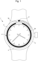
- FIG. 1 is a schematic representation of a watch 1 comprising a case 2 having a caseband 6 and a hollow bezel 3 provided with a near-field communication device 4 of the NFC type (acronym for “Near Field Communication”).
- a near-field communication device 4 can participate in carrying out a contactless electronic payment.
- such a device 4 is then a contactless electronic payment device.
- This near-field communication device 4 comprises at least one microcircuit 5a which may be an integrated circuit and an antenna 5b preferably of circular shape which may be wound in material electrically conductive, such as copper or made on a printed circuit board (or PCB) and which is connected to said microcircuit 5a.
- a microcircuit 5a which may be an integrated circuit and an antenna 5b preferably of circular shape which may be wound in material electrically conductive, such as copper or made on a printed circuit board (or PCB) and which is connected to said microcircuit 5a.
- the watch 1 comprises a bezel 3 which can be easily disassembled/disassembled in particular to change the near-field communication device 4 which would be defective and this, without damaging this bezel 3 and by extension the case 2 of watch 1.
- this bezel 3 also participates in allowing such a device 4 to be integrated into this watch 1 in a simpler and more economical manner. It will be noted that such a bezel 3 can be unidirectional or bidirectional or even a non-rotating bezel.
- This watch 1 can be a wristwatch or a mechanical watch or even a connected watch.
- This watch 1 can be waterproof and in this configuration it can be a sports watch such as a diving watch.
- the case 2 firstly comprises a caseband 6.
- the caseband 6 may be made of metal (e.g. steel, preferably stainless steel), or of a synthetic material (e.g. a composite material comprising a polymer matrix loaded with fibres, typically carbon) or of a dielectric, ceramic and/or electrically non-conductive material.
- the middle 6 has a circular outline.
- the middle 6 defines an interior space configured to accommodate a watch movement.
- This middle 6 includes horns on which a bracelet is intended to be attached for wearing the watch 1 on the wrist. If we ignore the horns, the middle 6 has a general symmetry of revolution around a central axis X.
- This watch case 2 of watch 1 comprises secondly, the bezel 3 which is removably mounted on the caseband 6.
- This bezel 3 is in fact mounted on this caseband 6 from at least one fixing element removable, in particular of the clipping or nesting type.
- a fixing element makes it possible to assemble and disassemble the bezel 3 from the caseband 6 easily, quickly and simply without damaging them in order to ensure, for example, the maintenance of the near-field communication device 4.
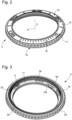
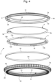
- this bezel 3 has an essentially annular shape. It comprises two covering elements 7a, 7b, a reversible fixing device 8 and a removable support element 11 of the near-field communication device 4. More precisely, this bezel 3 is formed by assembling the first covering element 7a with the second covering element 7b so as to define a housing in which the near-field communication device 4 is arranged. In particular, it will be noted that in this configuration the support element 11 is sandwiched between these two covering elements 7a, 7b.
- the reversible fixing device 8 comprises a fixing zone 9b and a connecting zone 9c as well as a clamping element 9a that we will describe later. It should be recalled that such a device 8 participates in the assembly of the first and second covering elements 7a, 7b by a clamping fit.
- the first covering element 7a comprises an external face 15 on which a graduation 16 is affixed or formed.
- the graduation comprises indexes, some of which are figurative and are in the form of numerals (preferably Arabic).
- One of the indexes, called the zero index 17 is in the form of a triangle pointing towards the inside of this first covering element 7a, to form an origin mark from which the user measures, in minutes, the time elapsed from a predetermined initial instant corresponding to a precise angular position of the bezel 3 relative to the caseband 6.
- This first covering element 7a also comprises an internal face 18, an internal peripheral wall 19 and an external peripheral wall.
- This first covering element 7a comprises an arrangement zone 20 for said at least one microcircuit 5a of the communication device 4 which is provided both in a part of the internal peripheral wall 19 and a part of the internal face 18.
- This arrangement zone 20 is preferably located behind the zero index 17.
- the first covering element 7a also comprises the reversible fixing zone 9b comprising a groove 10 defined on its external peripheral wall. Such a groove 10 is specifically configured to receive the clamping element 9a.
- This clamping element 9a may be a compressible seal that is smaller than the circumference (circumference) of the groove 10. Such a clamping element 9a is therefore arranged in the groove 10 by being stretched. Despite its smaller circumference, the clamping element 9a finds its place in this groove 10 thanks to its elastic properties, which allow it to be relaxed and which once placed in the groove 10 will shrink to press against the external peripheral wall in the groove 10.
- This reversible fixing zone 9b is able to cooperate with the reversible connecting zone 9c defined on an internal peripheral wall 21 of the second covering element 7b of the bezel 3.
- This connecting zone 9c is able to cooperate with an external surface 20 of the clamping element 9a mounted in the groove 10 of the fixing zone 9b in order to reversibly connect the first covering element 7a with the second covering element 7b. It will be noted that the connecting zone 9c is able to cooperate by friction with the external surface 20 of the clamping element 9a arranged in the groove 10.
- the diameter connecting two points of the external surface 20 of the clamping element 9a mounted on the first covering element 7a is substantially greater or strictly greater than the diameter connecting two points of the connection zone 9c of the second covering element 7b. It will be noted that the diameter connecting two points of the groove 10 of the first covering element 7a is substantially less or strictly less than the diameter connecting two points of the connection zone 9c of the second covering element 7b. Furthermore, it is understood that the diameter of the first covering element 7a without the clamping element 9a is substantially less or strictly less than that of the second covering element 7b.
- the second covering element 7b comprises an inner face which is contiguous to its inner peripheral wall 21.
- This inner face is in particular configured to be a support face of the support element 11 of the bezel 3 when the first and second covering elements 7a, 7b are assembled.
- This second covering element 7b comprises an outer face 22 opposite the inner face and which extends opposite the middle part 6, and more precisely opposite a portion of the middle part 6 provided for the removable attachment of the bezel 3.
- This outer face 22 comprises a toothed crown 23 of this bezel 3 which is used for the angular indexing of the bezel 3 relative to the middle part 6.
- This toothed crown 23 comprises a peripheral series of teeth, each tooth of which is asymmetrical and comprises an inclined ramp and a vertical stop surface, possibly connected by a horizontal plate.
- This second covering element 7b is also provided with an external peripheral wall on which a gripping zone 24 of the bezel 3 is defined.
- the bezel 3 comprises the removable support element 11 of the near-field communication device 4. More specifically, this support element 11 is provided with an upper face 13a comprising a reception area 12b of the antenna 5b of said communication device 4. This reception area 12b on which said antenna 5b is arranged is in particular included in an inclined plane.
- This support element 11 also comprises a recess 12a, or a through opening, in which said at least one microcircuit 5a may be arranged in whole or in part.
- the receiving area 12b may comprise/form a protective magnetic screen such as ferrite by being covered with a layer of ferrite-based material.
- a protective magnetic screen such as ferrite by being covered with a layer of ferrite-based material.
- the portion of the inner peripheral wall and the inner face of the second covering element 7b located near said at least one microcircuit 5a may also comprise such a layer of material in order to form a magnetic screen with this support element 11.
- this support element 11 comprises a lower face 13b comprising a plurality of feet 14 capable of bearing on the internal face of the second covering element 7b of this bezel 3 when this second covering element 7b is assembled to the first covering element 7a.
- the first and second covering elements 7a, 7b, the clamping element 9a and the support element 11 are adapted to the operation of the near-field communication device 4 by being manufactured from dielectric and electrically non-conductive materials, such as for example plastic, ceramic, or any other synthetic material.
- the communication device 4 comprises a coating of waterproof material which makes it impermeable to water and moisture.
- This coating of material is also capable of making it resistant to high pressures which may be encountered during dives carried out by the wearer of the watch 1.
- This coating of material may comprise organic or inorganic layers or a combination of these two types of layers.
Landscapes
- Physics & Mathematics (AREA)
- General Physics & Mathematics (AREA)
- Engineering & Computer Science (AREA)
- Computer Networks & Wireless Communication (AREA)
- Business, Economics & Management (AREA)
- Signal Processing (AREA)
- Accounting & Taxation (AREA)
- Strategic Management (AREA)
- General Business, Economics & Management (AREA)
- Theoretical Computer Science (AREA)
- Electric Clocks (AREA)
- Structure Of Receivers (AREA)
Claims (14)
- Gehäuse (2) einer Uhr (1), das einen Mittelteil (6) und eine hohle Lünette (3) beinhaltet, die mit einer Nahfeld-Kommunikationsvorrichtung (4) versehen ist, die mindestens einen mit einer Antenne (5b) verbundenen Mikroschaltkreis (5a) umfasst, wobei die Lünette (3) abnehmbar auf dem Mittelteil (6) montiert ist, und aus einem Zusammenbau von zwei Verkleidungselementen (7a, 7b) gebildet ist, die eine Aufnahme definieren können, in der die Nahfeld-Kommunikationsvorrichtung (4) angeordnet ist, wobei das erste und zweite Verkleidungselement (7a, 7b) der Lünette (3) ausgehend von einer umkehrbaren Befestigungsvorrichtung (8) miteinander zusammengebaut sind, dadurch gekennzeichnet, dass das erste Verkleidungselement (7a) einen umkehrbaren Befestigungsbereich (9b) umfasst, der eine Nut (10) umfasst, die an einer äußeren Umfangswand des ersten Verkleidungselements (7a) definiert ist, wobei die Nut (10) konfiguriert ist, um ein Klemmelement (9a) der umkehrbaren Befestigungsvorrichtung (8) aufzunehmen.
- Gehäuse (2) nach dem vorstehenden Anspruch, dadurch gekennzeichnet, dass das Klemmelement (9a) eine komprimierbare Dichtung ist.
- Gehäuse (2) nach einem der vorstehenden Ansprüche, dadurch gekennzeichnet, dass das zweite Verkleidungselement (7b) einen umkehrbaren Verbindungsbereich (9c) umfasst, der durch Reibung mit einem Klemmelement (9a) zusammenwirken kann, das in einer Nut (10) angeordnet ist, die im ersten Verkleidungselement (7a) umfasst ist.
- Gehäuse (2) nach einem der vorstehenden Ansprüche, dadurch gekennzeichnet, dass die Lünette (3) ein abnehmbares Trägerelement (11) für die Nahfeld-Kommunikationsvorrichtung (4) umfasst.
- Gehäuse (2) nach dem vorstehenden Anspruch, dadurch gekennzeichnet, dass das Trägerelement (11) auf seiner Oberseite (13a) einen Empfangsbereich (12b) insbesondere als geneigte Ebene umfasst, der die Antenne (5b) aufnehmen kann.
- Gehäuse (2) nach dem vorstehenden Anspruch, dadurch gekennzeichnet, dass der Aufnahmebereich (12b) des Trägerelements (11) eine magnetische Abschirmung wie Ferrit umfasst oder daraus gebildet ist.
- Gehäuse (2) nach einem der Ansprüche 4 bis 6, dadurch gekennzeichnet, dass das Trägerelement (11) eine Aussparung (12a) umfasst, in der der mindestens eine Mikroschaltkreis (5a) ganz oder teilweise angeordnet werden kann.
- Gehäuse (2) nach einem der Ansprüche 4 bis 7, dadurch gekennzeichnet, dass das Trägerelement (11) auf seiner Unterseite (13b) mindestens zwei Füße (14) umfasst, die auf einer Innenseite (15) des zweiten Verkleidungselements (7b) der Lünette (3) aufliegen können, wenn dieses zweite Verkleidungselement (7b) mit dem ersten Verkleidungselement (7a) zusammengebaut wird.
- Gehäuse (2) nach dem vorstehenden Anspruch, dadurch gekennzeichnet, dass das erste und zweite Verkleidungselement (7a, 7b), das abnehmbare Trägerelement (11) und das Klemmelement (9a) aus mindestens einem dielektrischen und/oder elektrisch nicht leitfähigen Werkstoff hergestellt sind.
- Gehäuse (2) nach einem der vorstehenden Ansprüche, dadurch gekennzeichnet, dass die Lünette (3) ausgehend von mindestens einem abnehmbaren Befestigungselement, insbesondere vom Typ Clip, am Mittelteil (6) befestigt ist.
- Gehäuse (2) nach einem der vorstehenden Ansprüche, dadurch gekennzeichnet, dass die Nahfeld-Kommunikationsvorrichtung (4) einen Verguss aus dichtem Werkstoff umfasst, der die Vorrichtung (4) für Wasser und/oder Feuchtigkeit undurchlässig machen kann.
- Gehäuse (2) nach einem der vorstehenden Ansprüche, dadurch gekennzeichnet, dass die Nahfeld-Kommunikationsvorrichtung (4) eine kontaktlose elektronische Zahlungsvorrichtung ist.
- Uhr (1), die ein Gehäuse (2) beinhaltet, das eine Nahfeld-Kommunikationsvorrichtung (4) nach den Ansprüchen 1 bis 12 umfasst.
- Uhr (1) nach dem vorstehenden Anspruch, dadurch gekennzeichnet, dass sie dicht ist.
Priority Applications (4)
| Application Number | Priority Date | Filing Date | Title |
|---|---|---|---|
| EP20210655.5A EP4006654B1 (de) | 2020-11-30 | 2020-11-30 | Armbanduhrengehäuse, das eine vorrichtung zur nahfeldkommunikation umfasst |
| US17/495,145 US12353174B2 (en) | 2020-11-30 | 2021-10-06 | Watch case comprising a near-field communication device |
| JP2021170700A JP7181369B2 (ja) | 2020-11-30 | 2021-10-19 | 近距離無線通信デバイスを備える携行型時計ケース |
| CN202111441111.2A CN114578674B (zh) | 2020-11-30 | 2021-11-30 | 包括近场通信设备的表的表壳 |
Applications Claiming Priority (1)
| Application Number | Priority Date | Filing Date | Title |
|---|---|---|---|
| EP20210655.5A EP4006654B1 (de) | 2020-11-30 | 2020-11-30 | Armbanduhrengehäuse, das eine vorrichtung zur nahfeldkommunikation umfasst |
Publications (2)
| Publication Number | Publication Date |
|---|---|
| EP4006654A1 EP4006654A1 (de) | 2022-06-01 |
| EP4006654B1 true EP4006654B1 (de) | 2025-01-01 |
Family
ID=73646193
Family Applications (1)
| Application Number | Title | Priority Date | Filing Date |
|---|---|---|---|
| EP20210655.5A Active EP4006654B1 (de) | 2020-11-30 | 2020-11-30 | Armbanduhrengehäuse, das eine vorrichtung zur nahfeldkommunikation umfasst |
Country Status (4)
| Country | Link |
|---|---|
| US (1) | US12353174B2 (de) |
| EP (1) | EP4006654B1 (de) |
| JP (1) | JP7181369B2 (de) |
| CN (1) | CN114578674B (de) |
Family Cites Families (19)
| Publication number | Priority date | Publication date | Assignee | Title |
|---|---|---|---|---|
| JPS5241898Y2 (de) * | 1972-12-08 | 1977-09-22 | ||
| EP0844685B1 (de) * | 1996-11-22 | 2003-03-05 | Eta SA Fabriques d'Ebauches | Uhr mit Antenne zum Empfangen und/oder Aussenden von Funksignalen |
| CH690525A5 (fr) | 1996-11-22 | 2000-09-29 | Ebauchesfabrik Eta Ag | Pièce d'horlogerie comportant une antenne de réception et/ou de transmission d'un signal radio-diffusé. |
| JP2004294110A (ja) * | 2003-03-25 | 2004-10-21 | Matsushita Electric Works Ltd | オフセット電圧補正装置 |
| KR200406111Y1 (ko) | 2005-11-01 | 2006-01-20 | 김재섭 | 교통카드 겸용 손목시계 |
| EP1840678B1 (de) | 2006-03-30 | 2010-09-01 | Richemont International S.A. | Umkehrbare Uhr |
| FR2988886A1 (fr) * | 2012-03-30 | 2013-10-04 | France Telecom | Coque pour telephone mobile et terminal mobile |
| JP5998795B2 (ja) * | 2012-09-24 | 2016-09-28 | セイコーエプソン株式会社 | アンテナ内蔵式電子時計 |
| JP6368920B2 (ja) * | 2013-09-27 | 2018-08-08 | パナソニックIpマネジメント株式会社 | 近距離通信素子と、それを搭載した電子機器 |
| TWI511682B (zh) * | 2013-11-04 | 2015-12-11 | Sheng Hsin Liao | 可攜式模組堆疊裝置 |
| KR20160052253A (ko) | 2014-11-04 | 2016-05-12 | 삼성전자주식회사 | 안테나 장치 및 그것을 포함하는 전자 장치 |
| CH711231A2 (fr) | 2015-06-19 | 2016-12-30 | Omega Sa | Bracelet de montre. |
| EP3112958B1 (de) * | 2015-07-01 | 2022-03-16 | Bulgari Horlogerie S.A. | Uhr umfassend eine vorrichtung zur nahfeldkommunikation |
| EP3141969A1 (de) * | 2015-09-10 | 2017-03-15 | Omega SA | Verkleidungselement mit integriertem kommunikationsschaltkreis |
| CN105361368B (zh) | 2015-11-25 | 2017-11-17 | 广州合利宝支付科技有限公司 | 一种移动支付系统 |
| EP3343450B1 (de) | 2016-12-29 | 2020-02-05 | The Swatch Group Research and Development Ltd | Tragbarer gegenstand, der eine nahfeldverbindungsvorrichtung umfasst |
| CH713968B1 (fr) | 2017-07-11 | 2021-05-31 | Winwatch Ip Ltd | Verre de montre comprenant un dispositif de communication en champ proche NFC et montre équipée d'un tel verre. |
| US10285643B2 (en) | 2017-09-11 | 2019-05-14 | Apple Inc. | Retention system for electronic devices |
| CN211630640U (zh) | 2020-02-19 | 2020-10-02 | Oppo广东移动通信有限公司 | 固定组件及电子设备 |
-
2020
- 2020-11-30 EP EP20210655.5A patent/EP4006654B1/de active Active
-
2021
- 2021-10-06 US US17/495,145 patent/US12353174B2/en active Active
- 2021-10-19 JP JP2021170700A patent/JP7181369B2/ja active Active
- 2021-11-30 CN CN202111441111.2A patent/CN114578674B/zh active Active
Also Published As
| Publication number | Publication date |
|---|---|
| US20220171345A1 (en) | 2022-06-02 |
| EP4006654A1 (de) | 2022-06-01 |
| JP2022087018A (ja) | 2022-06-09 |
| JP7181369B2 (ja) | 2022-11-30 |
| CN114578674B (zh) | 2025-03-28 |
| CN114578674A (zh) | 2022-06-03 |
| US12353174B2 (en) | 2025-07-08 |
Similar Documents
| Publication | Publication Date | Title |
|---|---|---|
| EP0221233B1 (de) | Aus hartem Material hergestelltes Uhrengehäuse | |
| EP3182223B1 (de) | Uhrenarmband | |
| EP0098239B1 (de) | Armbanduhr mit einem mittels eines Scharnieres an dem Gehäuse befestigten Band | |
| EP1950632A1 (de) | Uhr mit polygonaler Lünette | |
| EP3119232B1 (de) | Uhrenarmband | |
| EP1378805A1 (de) | Uhrwerk mit Antenne | |
| CH690525A5 (fr) | Pièce d'horlogerie comportant une antenne de réception et/ou de transmission d'un signal radio-diffusé. | |
| EP4145230B1 (de) | Aussenring für uhr | |
| EP4006654B1 (de) | Armbanduhrengehäuse, das eine vorrichtung zur nahfeldkommunikation umfasst | |
| EP0525488B1 (de) | Uhr mit einem verdrehbaren Reif | |
| EP4006653B1 (de) | Armbanduhrengehäuse, das eine kontrollvorrichtung einer nahfeldkommunikationsvorrichtung umfasst | |
| CH718101A2 (fr) | Boîte de montre comprenant un dispositif de communication en champ proche. | |
| CH690870A5 (fr) | Boîte de montre étanche. | |
| EP0844685B1 (de) | Uhr mit Antenne zum Empfangen und/oder Aussenden von Funksignalen | |
| EP4176755A1 (de) | Anbringung eines faserstrangs eines armbands an einem armbanduhrgehäuse | |
| EP3712714B1 (de) | Zifferblat für eine universaluhr | |
| CH708959B1 (fr) | Boîte de montre comprenant une lunette tournante. | |
| CH718100A2 (fr) | Boîte de montre comprenant un dispositif de contrôle d'un dispositif de communication en champ proche. | |
| EP1544696B1 (de) | Tragbares elektronisches Gerät, das mit einem Drucksensor ausgerüstet ist | |
| EP0269872A1 (de) | Uhrengehäuse | |
| CH721182A2 (fr) | Lunette comprenant un dispositif de communication en champ proche | |
| CH257783A (fr) | Montre. | |
| EP1975748B1 (de) | Armbanduhrgehäuse | |
| EP3974914B1 (de) | Vorrichtung zum blockieren eines uhrwerks | |
| EP1980921B1 (de) | Uhr mit einer drehbaren Lunette |
Legal Events
| Date | Code | Title | Description |
|---|---|---|---|
| PUAI | Public reference made under article 153(3) epc to a published international application that has entered the european phase |
Free format text: ORIGINAL CODE: 0009012 |
|
| STAA | Information on the status of an ep patent application or granted ep patent |
Free format text: STATUS: THE APPLICATION HAS BEEN PUBLISHED |
|
| AK | Designated contracting states |
Kind code of ref document: A1 Designated state(s): AL AT BE BG CH CY CZ DE DK EE ES FI FR GB GR HR HU IE IS IT LI LT LU LV MC MK MT NL NO PL PT RO RS SE SI SK SM TR |
|
| STAA | Information on the status of an ep patent application or granted ep patent |
Free format text: STATUS: REQUEST FOR EXAMINATION WAS MADE |
|
| 17P | Request for examination filed |
Effective date: 20221201 |
|
| RBV | Designated contracting states (corrected) |
Designated state(s): AL AT BE BG CH CY CZ DE DK EE ES FI FR GB GR HR HU IE IS IT LI LT LU LV MC MK MT NL NO PL PT RO RS SE SI SK SM TR |
|
| P01 | Opt-out of the competence of the unified patent court (upc) registered |
Effective date: 20230615 |
|
| GRAP | Despatch of communication of intention to grant a patent |
Free format text: ORIGINAL CODE: EPIDOSNIGR1 |
|
| STAA | Information on the status of an ep patent application or granted ep patent |
Free format text: STATUS: GRANT OF PATENT IS INTENDED |
|
| RIC1 | Information provided on ipc code assigned before grant |
Ipc: G04B 47/04 20060101ALI20240718BHEP Ipc: G04B 47/00 20060101ALI20240718BHEP Ipc: G04B 19/28 20060101ALI20240718BHEP Ipc: G04R 20/28 20130101ALI20240718BHEP Ipc: G04R 60/08 20130101AFI20240718BHEP |
|
| INTG | Intention to grant announced |
Effective date: 20240802 |
|
| GRAS | Grant fee paid |
Free format text: ORIGINAL CODE: EPIDOSNIGR3 |
|
| GRAA | (expected) grant |
Free format text: ORIGINAL CODE: 0009210 |
|
| STAA | Information on the status of an ep patent application or granted ep patent |
Free format text: STATUS: THE PATENT HAS BEEN GRANTED |
|
| AK | Designated contracting states |
Kind code of ref document: B1 Designated state(s): AL AT BE BG CH CY CZ DE DK EE ES FI FR GB GR HR HU IE IS IT LI LT LU LV MC MK MT NL NO PL PT RO RS SE SI SK SM TR |
|
| REG | Reference to a national code |
Ref country code: GB Ref legal event code: FG4D Free format text: NOT ENGLISH |
|
| REG | Reference to a national code |
Ref country code: DE Ref legal event code: R096 Ref document number: 602020043987 Country of ref document: DE |
|
| REG | Reference to a national code |
Ref country code: CH Ref legal event code: EP |
|
| REG | Reference to a national code |
Ref country code: IE Ref legal event code: FG4D Free format text: LANGUAGE OF EP DOCUMENT: FRENCH |
|
| REG | Reference to a national code |
Ref country code: LT Ref legal event code: MG9D |
|
| REG | Reference to a national code |
Ref country code: NL Ref legal event code: MP Effective date: 20250101 |
|
| REG | Reference to a national code |
Ref country code: AT Ref legal event code: MK05 Ref document number: 1756877 Country of ref document: AT Kind code of ref document: T Effective date: 20250101 |
|
| PG25 | Lapsed in a contracting state [announced via postgrant information from national office to epo] |
Ref country code: NL Free format text: LAPSE BECAUSE OF FAILURE TO SUBMIT A TRANSLATION OF THE DESCRIPTION OR TO PAY THE FEE WITHIN THE PRESCRIBED TIME-LIMIT Effective date: 20250101 |
|
| PG25 | Lapsed in a contracting state [announced via postgrant information from national office to epo] |
Ref country code: FI Free format text: LAPSE BECAUSE OF FAILURE TO SUBMIT A TRANSLATION OF THE DESCRIPTION OR TO PAY THE FEE WITHIN THE PRESCRIBED TIME-LIMIT Effective date: 20250101 |
|
| PG25 | Lapsed in a contracting state [announced via postgrant information from national office to epo] |
Ref country code: PL Free format text: LAPSE BECAUSE OF FAILURE TO SUBMIT A TRANSLATION OF THE DESCRIPTION OR TO PAY THE FEE WITHIN THE PRESCRIBED TIME-LIMIT Effective date: 20250101 |
|
| PG25 | Lapsed in a contracting state [announced via postgrant information from national office to epo] |
Ref country code: ES Free format text: LAPSE BECAUSE OF FAILURE TO SUBMIT A TRANSLATION OF THE DESCRIPTION OR TO PAY THE FEE WITHIN THE PRESCRIBED TIME-LIMIT Effective date: 20250101 |
|
| PG25 | Lapsed in a contracting state [announced via postgrant information from national office to epo] |
Ref country code: IS Free format text: LAPSE BECAUSE OF FAILURE TO SUBMIT A TRANSLATION OF THE DESCRIPTION OR TO PAY THE FEE WITHIN THE PRESCRIBED TIME-LIMIT Effective date: 20250501 Ref country code: NO Free format text: LAPSE BECAUSE OF FAILURE TO SUBMIT A TRANSLATION OF THE DESCRIPTION OR TO PAY THE FEE WITHIN THE PRESCRIBED TIME-LIMIT Effective date: 20250401 |
|
| PG25 | Lapsed in a contracting state [announced via postgrant information from national office to epo] |
Ref country code: HR Free format text: LAPSE BECAUSE OF FAILURE TO SUBMIT A TRANSLATION OF THE DESCRIPTION OR TO PAY THE FEE WITHIN THE PRESCRIBED TIME-LIMIT Effective date: 20250101 |
|
| PG25 | Lapsed in a contracting state [announced via postgrant information from national office to epo] |
Ref country code: LV Free format text: LAPSE BECAUSE OF FAILURE TO SUBMIT A TRANSLATION OF THE DESCRIPTION OR TO PAY THE FEE WITHIN THE PRESCRIBED TIME-LIMIT Effective date: 20250101 Ref country code: PT Free format text: LAPSE BECAUSE OF FAILURE TO SUBMIT A TRANSLATION OF THE DESCRIPTION OR TO PAY THE FEE WITHIN THE PRESCRIBED TIME-LIMIT Effective date: 20250502 |
|
| PG25 | Lapsed in a contracting state [announced via postgrant information from national office to epo] |
Ref country code: GR Free format text: LAPSE BECAUSE OF FAILURE TO SUBMIT A TRANSLATION OF THE DESCRIPTION OR TO PAY THE FEE WITHIN THE PRESCRIBED TIME-LIMIT Effective date: 20250402 Ref country code: BG Free format text: LAPSE BECAUSE OF FAILURE TO SUBMIT A TRANSLATION OF THE DESCRIPTION OR TO PAY THE FEE WITHIN THE PRESCRIBED TIME-LIMIT Effective date: 20250101 |
|
| PG25 | Lapsed in a contracting state [announced via postgrant information from national office to epo] |
Ref country code: AT Free format text: LAPSE BECAUSE OF FAILURE TO SUBMIT A TRANSLATION OF THE DESCRIPTION OR TO PAY THE FEE WITHIN THE PRESCRIBED TIME-LIMIT Effective date: 20250101 |
|
| PG25 | Lapsed in a contracting state [announced via postgrant information from national office to epo] |
Ref country code: CZ Free format text: LAPSE BECAUSE OF FAILURE TO SUBMIT A TRANSLATION OF THE DESCRIPTION OR TO PAY THE FEE WITHIN THE PRESCRIBED TIME-LIMIT Effective date: 20250101 |
|
| PG25 | Lapsed in a contracting state [announced via postgrant information from national office to epo] |
Ref country code: SE Free format text: LAPSE BECAUSE OF FAILURE TO SUBMIT A TRANSLATION OF THE DESCRIPTION OR TO PAY THE FEE WITHIN THE PRESCRIBED TIME-LIMIT Effective date: 20250101 |
|
| REG | Reference to a national code |
Ref country code: DE Ref legal event code: R097 Ref document number: 602020043987 Country of ref document: DE |
|
| PG25 | Lapsed in a contracting state [announced via postgrant information from national office to epo] |
Ref country code: SM Free format text: LAPSE BECAUSE OF FAILURE TO SUBMIT A TRANSLATION OF THE DESCRIPTION OR TO PAY THE FEE WITHIN THE PRESCRIBED TIME-LIMIT Effective date: 20250101 |
|
| PG25 | Lapsed in a contracting state [announced via postgrant information from national office to epo] |
Ref country code: DK Free format text: LAPSE BECAUSE OF FAILURE TO SUBMIT A TRANSLATION OF THE DESCRIPTION OR TO PAY THE FEE WITHIN THE PRESCRIBED TIME-LIMIT Effective date: 20250101 |
|
| PG25 | Lapsed in a contracting state [announced via postgrant information from national office to epo] |
Ref country code: IT Free format text: LAPSE BECAUSE OF FAILURE TO SUBMIT A TRANSLATION OF THE DESCRIPTION OR TO PAY THE FEE WITHIN THE PRESCRIBED TIME-LIMIT Effective date: 20250101 |
|
| PG25 | Lapsed in a contracting state [announced via postgrant information from national office to epo] |
Ref country code: EE Free format text: LAPSE BECAUSE OF FAILURE TO SUBMIT A TRANSLATION OF THE DESCRIPTION OR TO PAY THE FEE WITHIN THE PRESCRIBED TIME-LIMIT Effective date: 20250101 |
|
| PG25 | Lapsed in a contracting state [announced via postgrant information from national office to epo] |
Ref country code: RO Free format text: LAPSE BECAUSE OF FAILURE TO SUBMIT A TRANSLATION OF THE DESCRIPTION OR TO PAY THE FEE WITHIN THE PRESCRIBED TIME-LIMIT Effective date: 20250101 |
|
| PG25 | Lapsed in a contracting state [announced via postgrant information from national office to epo] |
Ref country code: SK Free format text: LAPSE BECAUSE OF FAILURE TO SUBMIT A TRANSLATION OF THE DESCRIPTION OR TO PAY THE FEE WITHIN THE PRESCRIBED TIME-LIMIT Effective date: 20250101 |
|
| PLBE | No opposition filed within time limit |
Free format text: ORIGINAL CODE: 0009261 |
|
| STAA | Information on the status of an ep patent application or granted ep patent |
Free format text: STATUS: NO OPPOSITION FILED WITHIN TIME LIMIT |
|
| REG | Reference to a national code |
Ref country code: CH Ref legal event code: L10 Free format text: ST27 STATUS EVENT CODE: U-0-0-L10-L00 (AS PROVIDED BY THE NATIONAL OFFICE) Effective date: 20251112 |
|
| REG | Reference to a national code |
Ref country code: CH Ref legal event code: U11 Free format text: ST27 STATUS EVENT CODE: U-0-0-U10-U11 (AS PROVIDED BY THE NATIONAL OFFICE) Effective date: 20251201 |
|
| 26N | No opposition filed |
Effective date: 20251002 |
|
| PGFP | Annual fee paid to national office [announced via postgrant information from national office to epo] |
Ref country code: DE Payment date: 20251022 Year of fee payment: 6 |
|
| PGFP | Annual fee paid to national office [announced via postgrant information from national office to epo] |
Ref country code: FR Payment date: 20251022 Year of fee payment: 6 |
|
| PGFP | Annual fee paid to national office [announced via postgrant information from national office to epo] |
Ref country code: CH Payment date: 20251201 Year of fee payment: 6 |