EP4006429B1 - Ein kochgerät mit einer flexiblen halterung - Google Patents
Ein kochgerät mit einer flexiblen halterung Download PDFInfo
- Publication number
- EP4006429B1 EP4006429B1 EP21211182.7A EP21211182A EP4006429B1 EP 4006429 B1 EP4006429 B1 EP 4006429B1 EP 21211182 A EP21211182 A EP 21211182A EP 4006429 B1 EP4006429 B1 EP 4006429B1
- Authority
- EP
- European Patent Office
- Prior art keywords
- connecting member
- cooking
- rest
- support frame
- cooking appliance
- Prior art date
- Legal status (The legal status is an assumption and is not a legal conclusion. Google has not performed a legal analysis and makes no representation as to the accuracy of the status listed.)
- Active
Links
Images


Classifications
-
- A—HUMAN NECESSITIES
- A47—FURNITURE; DOMESTIC ARTICLES OR APPLIANCES; COFFEE MILLS; SPICE MILLS; SUCTION CLEANERS IN GENERAL
- A47J—KITCHEN EQUIPMENT; COFFEE MILLS; SPICE MILLS; APPARATUS FOR MAKING BEVERAGES
- A47J37/00—Baking; Roasting; Grilling; Frying
- A47J37/06—Roasters; Grills; Sandwich grills
- A47J37/0623—Small-size cooking ovens, i.e. defining an at least partially closed cooking cavity
- A47J37/0664—Accessories
-
- F—MECHANICAL ENGINEERING; LIGHTING; HEATING; WEAPONS; BLASTING
- F24—HEATING; RANGES; VENTILATING
- F24C—DOMESTIC STOVES OR RANGES ; DETAILS OF DOMESTIC STOVES OR RANGES, OF GENERAL APPLICATION
- F24C15/00—Details
- F24C15/08—Foundations or supports plates; Legs or pillars; Casings; Wheels
Definitions
- the present disclosure generally relates to a bracket for a cooking appliance, and more specifically, to a flexible bracket configured to absorb the dimensional changes of a cooking vessel during a cooking procedure.
- Prior art can be found in the documents DE 71 05 443 U and US 4 161 939 A .
- the invention is defined by the features of claim 1.
- a cooking appliance includes a support frame and a cooking vessel that is spaced-apart from the support frame to define a spacing therebetween.
- the cooking vessel is operable between at-rest and expanded conditions.
- An outer surface of the cooking vessel approaches the support frame when the cooking vessel moves from the at-rest condition to the expanded condition.
- a bracket interconnects the support frame and the cooking vessel.
- the bracket includes a first mounting member operably coupled to the cooking vessel and a second mounting member operably coupled to the support frame.
- At least one flexibly resilient connecting member interconnects the first and second mounting members and spans the spacing between the support frame and the cooking vessel.
- a bracket for a cooking appliance includes a first mounting member spaced-apart from a second mounting member to define a gap therebetween.
- a first connecting member spans the gap between the first and second mounting members.
- the first connecting member includes a first portion coupled to the first mounting member, second portion coupled to the second mounting member, and an intermediate portion disposed therebetween.
- the first and second portions of the first connecting member are coupled to opposite ends of the intermediate portion at first and second deflection creases, respectively.
- a second connecting member spans the gap between the first and second mounting members and includes a first portion that is coupled to the first mounting member, a second portion coupled to the second mounting member, and an intermediate portion disposed therebetween.
- the first and second portions of the second connecting member are coupled to opposite ends of the intermediate portion at first and second deflection creases, respectively
- a bracket for a cooking appliance includes a first mounting member and a second mounting member spaced-apart from the first mounting member to define a gap having a length disposed therebetween.
- At least one connecting member interconnects the first and second mounting members.
- the at least one connecting member includes at least one deflection crease and is operable between at-rest and loaded conditions. The length of the gap decreases as the at least one connecting member moves from the at-rest condition to the loaded condition.
- a bracket 10 having a first mounting member 12 and a second mounting member 14.
- the first mounting member 12 and the second mounting member 14 are spaced-apart from one another to define a gap 20 therebetween.
- the first mounting member 12 is both vertically and horizontally offset from the second mounting member 14 by first and second connecting members 22, 24 which span the gap 20 to interconnect the first and second mounting members 12, 14, as further described below.
- the first mounting member 12 includes a generally planar body portion 13 having upper and lower mounting apertures 16, 17 disposed therethrough.
- the second mounting member 14 includes a generally planar body portion 15 having upper and lower mounting apertures 18, 19 disposed therethrough.
- the first and second connecting members 22, 24 may be referred to herein as upper and lower connecting members. It is also contemplated that the bracket 10 may include more than two connecting members in various embodiments.
- the first connecting member 22 includes a first portion 30 and a second portion 32 which are interconnected by an intermediate portion 34 at first and second deflection creases 36, 38, respectively.
- the second connecting member 24 includes a first portion 40 and a second portion 42 which are interconnected by an intermediate portion 44 at first and second deflection creases 46, 48, respectively.
- the first and second connecting members 22, 24 are non-linear members which include a generally Z-shaped configuration in the illustrated embodiment.
- the term "deflection crease” is meant to indicate a bend in a portion of the bracket 10, wherein an angle is provided therebetween.
- the bend provided by the first and second deflection creases 36, 38 and 46, 48 of the present concept directs the location of contraction of the bracket 10.
- the first and second connecting members 22, 24 are contemplated to be flexibly resilient members configured to flex at the first and second deflection creases 36, 38 and 46, 48, respectively.
- the first and second connecting members 22, 24 are contemplated to inwardly flex at the respective first and second deflection creases 36, 38 and 46, 48, such that the first and second connecting members 22, 24 are operable between at-rest and loaded conditions.
- the bracket 10 is operable between at-rest and contracted positions, wherein the first and second mounting members 12, 14 approach one another to decrease a length L of the gap 20, as best shown in FIGS. 4 and 5 , as the bracket 10 moves from the at-rest position to the contracted position and the first and second connecting members 22, 24 move from the at-rest condition to the loaded condition.
- the first and second connecting members 22, 24 are vertically spaced-apart a distance D to define a thermal break 26 therebetween.
- FIG. 3 another embodiment of the bracket 10A is shown, wherein the upper and lower mounting apertures 16, 17 ( FIGS. 1 and 2 ) of the first mounting member 12 have been replaced by upper and lower mounting bosses 16A, 17A.
- the upper and lower mounting bosses 16A, 17A outwardly extend from an upper surface 13A of the planar body portion 13 of the first mounting member 12. It is contemplated that the upper and lower mounting bosses 16A, 17A may be received in reciprocal mounting apertures disposed on a cooking vessel, as further described below.
- the bracket 10 is shown in the at-rest position, wherein the gap 20 defined between the first and second mounting members 12, 14 includes an at-rest length L1.
- the bracket 10 is shown in the contracted position, wherein the gap 20 defined between the first and second mounting members 12, 14 includes a contracted length L2.
- the length L of gap 20 decreases from the at-rest length L1 to the contracted length L2.
- the length L of the gap 20 is greater when the bracket 10 is in the at-rest position as comparted to the contracted position.
- the bracket 10 is a flexible bracket which is contemplated to be biased towards the at-rest position shown in FIG. 4 .
- the resiliency of the bracket 10 is provided by the first and second connecting members 22, 24, as the first and second connecting members 22, 24 are flexibly resilient between the at-rest and loaded conditions. In the loaded conditions, the first and second connecting members 22, 24 store a spring force that biases the bracket 10 to the at-rest position.
- the contraction of the bracket 10A is also shown in a similar manner in FIGS. 6 and 7 .
- the bracket 10 is configured to flex or bend at the predetermined positions of the first and second deflection creases 36, 38 and 46, 48 of the first and second connecting members 22, 24.
- the first connecting member 22 flexes in a similar manner as described below.
- the second connecting member 24 includes the intermediate portion 44 having opposed first and second ends 44A, 44B.
- the first deflection crease 46 interconnects the first portion 40 of the second connecting member 24 with the intermediate portion 44 of the second connecting member 24 at the first end 44A thereof.
- a first angle A1 is defined at the first deflection crease 46 between the first portion 40 and intermediate portion 44 of the second connecting member 24.
- the second deflection crease 48 interconnects the second portion 42 of the second connecting member 24 with the intermediate portion 44 of the second connecting member 24 at the second end 44B thereof.
- a second angle A2 is defined at the second deflection crease 48 between the second portion 42 and intermediate portion 44 of the second connecting member 24.
- the bracket 10 is shown in the at-rest position.
- the first mounting member 12 of the bracket 10 moves in the direction as indicated by arrow 50 towards the second mounting member 14 to decrease the gap 20 therebetween.
- the first mounting member 12 moves towards the second mounting member 14 in response to an expansion force of a cooking cavity acting on the first mounting member 12, as further described below.
- the bracket 10 is biased towards the at-rest position, such that the first mounting member 12 moves away from the second mounting member 14, and the direction as indicated by arrow 52, as the imparting force is lessoned or removed from the first mounting member 12.
- the bracket 10 moves from the at-rest position, shown in FIG. 4 , to the contracted position, shown in FIG. 5 , the first and second angles A1, A2 decrease, thereby accounting for, or otherwise absorbing, the movement of the first mounting member 12.
- the second mounting member 14 may be a stationary member as mounted to a support frame, as further described below.
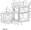
- a cooking appliance 60 is shown having upper and lower cooking vessels 62, 64. It is contemplated that the cooking appliance 60 may include a dual oven configuration, or a microwave and oven combination.
- the upper cooking vessel 62 includes an outer surface 63 surrounding a cooking cavity 68.
- a rear mounting plate 66 is shown on a rear portion of the upper cooking vessel 62, and is contemplated to be part of the outer surface 63 of the upper cooking vessel 62.
- the lower cooking vessel 64 includes an outer surface 65 that surrounds a cooking cavity 69.
- a rear mounting plate 67 is shown on a rear portion of the lower cooking vessel 64, and is contemplated to be part of the outer surface 65 of the lower cooking vessel 64.
- the cooking cavities 68, 69 of the respective cooking vessels 62, 64 are contemplated to be heated to desired cooking temperatures for cooking food item therein. As the cooking cavities 68, 69 are heated, the outer surfaces 63, 65 of the respective cooking vessels 62, 64 are contemplated to expand. Thus, the bracket 10 of the present concept is configured to absorb this expansion during a cooking procedure.
- the cooking appliance 60 includes a support frame 70 having a front portion 71 and a rear portion 73.
- the rear portion 73 of the support frame 70 includes first and second frame members 72, 74 which are connected by upper and lower cross members 76, 78, in the embodiment of FIG. 8 .
- the front portion 71 of the support frame 70 includes first and second frame members 82, 84 that may be interconnected to one another by any number of cross members.
- the front portion 71 of the support frame 70 is interconnected with the rear portion 73 of the support frame 70 by upper and lower interconnecting supports 86, 88. It is contemplated that the front and rear portions 71, 73 of the support frame 70 may be interconnected by any number of interconnecting support members as necessary to support the upper and lower cooking vessels 62, 64 of the cooking appliance 60.
- a front plate 90 interconnects the upper and lower cooking vessels 62, 64 with the front portion 71 of the support frame 70. It is contemplated that this is a rigid coupling between the front plate 90 and the support frame 70.
- the movement of the upper and lower cooking vessels 62, 64 is directed towards the rear portions of the upper and lower cooking vessels 62, 64 given the rigid coupling between the front plate 90 and the front portion 71 of the support frame 70.
- the rear portions of the upper and lower cooking vessels 62, 64 are operably coupled to the rear portion 73 of the support frame 70 by a number of brackets 10 of the present concept, in order to absorb the expansion and contraction of the upper and lower cooking vessels 62, 64.
- the upper and lower cooking vessels 62, 64 are spaced-apart from the rear portion 73 of the support frame 70 to define a spacing 92 therebetween.
- the brackets 10 span the spacing 92 to interconnect the upper and lower cooking vessels 62, 64 with the rear portion 73 of the support frame 70.
- the outer surfaces 63, 65 of the upper and lower cooking vessels 62, 64 approach the rear portion 73 of the support frame 70 when the upper and lower cooking vessels 62, 64 moves from the at-rest condition to the expanded condition during a cooking procedure to close the spacing 92 therebetween.
- the bracket 10 interconnects the outer surface 63 of the upper cooking vessel 62 with the first frame member 72 of the rear portion 73 of the support frame 70.
- the first mounting member 12 of the bracket 10 is operably coupled to the rear mounting plate 66 of the upper cooking vessel 62 at the upper and lower mounting apertures 16, 17.
- the second mounting member 14 of the bracket 10 is operably coupled to an outer surface 72A of the first frame member 72 of the support frame 70 at upper and lower mounting apertures 18, 19. It is contemplated that the bracket 10 may be fastened to the rear mounting plate 66 and the first frame member 72 using fasteners mounted to the respective upper and lower mounting apertures 16, 17 and 18, 19.
- bracket 10 may be welded to the rear mounting plate 66 and the first frame member 72 at the respective upper and lower mounting apertures 16, 17 and 18, 19.
- upper and lower mounting apertures 67A and 67B are shown disposed through the rear mounting plate 66 of the upper cooking vessel 62 and are aligned with the upper and lower mounting apertures 16, 17 of the first mounting member 12 of the bracket 10.
- the associated upper and lower mounting apertures 67A, 67B and 16, 17 are aligned to receive a fastener therebetween to rigidly interconnect the bracket 10 with the upper cooking vessel 62.
- the first and second connecting members 22, 24 are configured to flex in response to the upper cooking vessel 62 moving between the at-rest and expanded conditions.
- the first mounting member 12 of the bracket 10 will move towards the second mounting member 14 of the bracket 10 as the bracket 10 moves from the at-rest position to the contracted position. Movement of the bracket 10 from the at-rest position to the contracted position is accounted for at the first and second connecting members 22, 24 moving from the at-rest condition to the loaded condition.
- the first and second connecting members 22, 24 are vertically spaced-apart a distance D to define the thermal break 26.
- the thermal break 26 is provided between the first and second mounting members 12, 14, to reduce thermal conductivity between the cooking appliance 60 and the support frame 70 thereof. In this way, the thermal break 26 provides a window positioned between the first and second mounting members 12, 14 of the bracket 10 to decrease the overall thermal bridge that would be present in a bracket without such a thermal break 26.
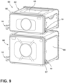
- the cooking appliance 60 is shown from a rear perspective view with the support frame 70 removed.
- the upper cooking vessel 62 is shown as having first and second brackets 10 disposed on opposite sides of the rear mounting plate 66.
- the lower cooking vessel 64 is shown as having first and second brackets 10 disposed on opposite sides of the rear mounting plate 67.
- brackets can be used to couple cooking vessels to a support frame as needed to properly support the cooking vessels on the support frame.
Landscapes
- Engineering & Computer Science (AREA)
- Chemical & Material Sciences (AREA)
- Combustion & Propulsion (AREA)
- Mechanical Engineering (AREA)
- General Engineering & Computer Science (AREA)
- Food Science & Technology (AREA)
- Baking, Grill, Roasting (AREA)
- Cookers (AREA)
Claims (11)
- Kochgerät (60), umfassend:einen Stützrahmen (70) mit einem vorderen Abschnitt (71) und einem hinteren Abschnitt (73), die durch Verbindungsstützen (86, 88) miteinander verbunden sind;einen Kochbehälter (62), der starr mit dem vorderen Abschnitt (71) des Stützrahmens (70) gekoppelt und vom hinteren Abschnitt (73) des Stützrahmens (70) beabstandet ist, um einen Zwischenraum (92) dazwischen zu definieren, wobei der Kochbehälter (62) zwischen einem Ruhezustand und einem Ausdehnungszustand betreibbar ist; undeine Halterung (10), die den hinteren Abschnitt (73) des Stützrahmens (70) und den Kochbehälter (62) miteinander verbindet,wobei die Halterung (10) ein erstes Befestigungselement (12), das betriebsfähig mit dem Kochbehälter (62) gekoppelt ist, ein zweites Befestigungselement (14), das betriebsfähig mit dem hinteren Abschnitt (73) des Stützrahmens (70) gekoppelt ist, und mindestens ein Verbindungselement (22) umfasst, das das erste und das zweite Befestigungselement (12, 14) miteinander verbindet, wobei das mindestens eine Verbindungselement (22) den Zwischenraum (92) zwischen dem hinteren Abschnitt (73) des Stützrahmens (70) und dem Kochbehälter (62) überbrückt, und wobei ferner das mindestens eine Verbindungselement (22) flexibel elastisch ist und dazu ausgelegt ist, sich als Reaktion auf die Bewegung des Kochbehälters (62) zwischen dem Ruhezustand und dem Ausdehnungszustand zu biegen,dadurch gekennzeichnet, dass das mindestens eine Verbindungselement (22) ein erstes und ein zweites Verbindungselement (22, 24) umfasst, und wobei das erste und das zweite Verbindungselement (22, 24) vertikal voneinander beabstandet sind, um eine thermische Trennung (26) dazwischen zu definieren, und wobei das erste und das zweite Verbindungselement (22, 24) jeweils eine Z-förmige Konfiguration aufweisen.
- Kochgerät (60) nach Anspruch 1, wobei sich eine Außenfläche (63) des Kochbehälters (62) dem Stützrahmen (70) nähert, wenn sich der Kochbehälter (62) aus dem Ruhezustand in den Ausdehnungszustand bewegt.
- Kochgerät (60) nach einem der Ansprüche 1-2, wobei das mindestens eine Verbindungselement (22) zwischen einem Ruhezustand und einem Belastungszustand betreibbar ist.
- Kochgerät (60) nach Anspruch 3, wobei sich das mindestens eine Verbindungselement (22) aus dem Ruhezustand in den Belastungszustand bewegt, wenn sich der Kochbehälter (62) aus dem Ruhezustand in den Ausdehnungszustand bewegt.
- Kochgerät (60) nach einem der Ansprüche 1-4, wobei das mindestens eine Verbindungselement (22) ein nichtlineares Element ist und einen ersten Abschnitt (30) und einen zweiten Abschnitt (32) mit einem dazwischen angeordneten Zwischenabschnitt (34) umfasst.
- Kochgerät (60) nach Anspruch 5, wobei der erste Abschnitt (30) und der zweite Abschnitt (32) des mindestens einen Verbindungselements (22) an entgegengesetzten Enden des Zwischenabschnitts (34) an einem ersten und einem zweiten Biegeknick (36, 38) verbunden sind.
- Kochgerät (60) nach Anspruch 6, wobei das mindestens eine Verbindungselement (22) dazu ausgelegt ist, sich an dem ersten und dem zweiten Biegeknick (36, 38) als Reaktion auf die Bewegung des Kochbehälters (62) zwischen dem Ruhezustand und dem Ausdehnungszustand zu biegen.
- Kochgerät (60) nach Anspruch 3, wobei sich das erste Befestigungselement (12) auf das zweite Befestigungselement (14) zubewegt, wenn sich das mindestens eine Verbindungselement (22) aus dem Ruhezustand in den Belastungszustand bewegt.
- Kochgerät (60) nach einem der Ansprüche 1-8, wobei das erste und das zweite Befestigungselement (12, 14) jeweils im Allgemeinen ebene Körperabschnitte (13, 15) mit darin angeordneten Befestigungsöffnungen (16, 17 und 18, 19) umfassen.
- Kochgerät (60) nach Anspruch 3, wobei das erste Befestigungselement (12) und das zweite Befestigungselement (14) voneinander beabstandet sind, um einen Spalt (20) dazwischen zu definieren.
- Kochgerät (60) nach Anspruch 10, wobei eine Länge (L1) des Spalts (20) größer ist, wenn sich das mindestens eine Verbindungselement (22) im Ruhezustand befindet, als eine Länge (L2) des Spalts (20), wenn sich das mindestens eine Verbindungselement (22) im Belastungszustand befindet, und wobei ferner das mindestens eine Verbindungselement (22) in Richtung der Ruheposition vorgespannt ist.
Applications Claiming Priority (1)
| Application Number | Priority Date | Filing Date | Title |
|---|---|---|---|
| US17/106,545 US11867405B2 (en) | 2020-11-30 | 2020-11-30 | Flexible bracket for a cooking appliance |
Publications (2)
| Publication Number | Publication Date |
|---|---|
| EP4006429A1 EP4006429A1 (de) | 2022-06-01 |
| EP4006429B1 true EP4006429B1 (de) | 2025-03-19 |
Family
ID=78820110
Family Applications (1)
| Application Number | Title | Priority Date | Filing Date |
|---|---|---|---|
| EP21211182.7A Active EP4006429B1 (de) | 2020-11-30 | 2021-11-29 | Ein kochgerät mit einer flexiblen halterung |
Country Status (3)
| Country | Link |
|---|---|
| US (1) | US11867405B2 (de) |
| EP (1) | EP4006429B1 (de) |
| CN (1) | CN114568966A (de) |
Families Citing this family (1)
| Publication number | Priority date | Publication date | Assignee | Title |
|---|---|---|---|---|
| BE1032015B1 (de) * | 2023-09-27 | 2025-04-28 | Miele & Cie | Gargerät, umfassend ein Gehäuse mit einem darin angeordneten Garraum |
Family Cites Families (31)
| Publication number | Priority date | Publication date | Assignee | Title |
|---|---|---|---|---|
| US2434811A (en) * | 1945-07-11 | 1948-01-20 | Crown Stove Works | Stove construction having top section securing means |
| US3038462A (en) * | 1960-07-21 | 1962-06-12 | Gen Electric | Oven liner |
| US3131684A (en) * | 1962-10-22 | 1964-05-05 | Gen Electric | Supporting and gasketing means for domestic cooking ovens |
| US3385280A (en) * | 1966-05-24 | 1968-05-28 | Westinghouse Electric Corp | Mounting arrangement for oven liner |
| US3636766A (en) * | 1970-05-11 | 1972-01-25 | Contamination Control Lab | Velocity meter |
| DE7105443U (de) | 1971-02-13 | 1971-11-11 | Siemens-Electrogeraete Gmbh | Herd |
| US4161939A (en) * | 1978-03-06 | 1979-07-24 | Chambers Corporation | Oven liner suspension assembly |
| US4651959A (en) * | 1985-09-20 | 1987-03-24 | Carrier Corporation | Mounting for a room air conditioner |
| US4848311A (en) * | 1988-03-11 | 1989-07-18 | General Electric Company | Method and apparatus for reducing side panel hot spots in a kitchen range |
| DE4422360A1 (de) | 1994-06-27 | 1996-01-04 | Bosch Siemens Hausgeraete | Wärme-Haushaltgerät |
| US6830299B2 (en) * | 2002-05-31 | 2004-12-14 | Kimball International, Inc. | Article of furniture having hidden slide |
| DE10314589B4 (de) | 2003-03-31 | 2021-06-24 | BSH Hausgeräte GmbH | Gargerät |
| DE10314510A1 (de) | 2003-03-31 | 2004-10-14 | BSH Bosch und Siemens Hausgeräte GmbH | Blechteil-Anordnung |
| KR20060086012A (ko) | 2005-01-25 | 2006-07-31 | 엘지전자 주식회사 | 오븐 캐비티의 지지구조 |
| US20070175885A1 (en) * | 2006-01-27 | 2007-08-02 | Brower David C | Modular steam oven construction method and related double cavity steam oven assembly |
| DE102006004378A1 (de) | 2006-01-31 | 2007-08-16 | BSH Bosch und Siemens Hausgeräte GmbH | Gargerät, insbesondere Hocheinbau-Gargerät, und Verfahren zum Herstellen eines Gargeräts |
| US7789081B2 (en) * | 2006-04-20 | 2010-09-07 | Whirlpool Corporation | Modular frame chassis for cooking range |
| CN201526097U (zh) * | 2009-09-11 | 2010-07-14 | 广东新元素板业有限公司 | 一种防火板的组合安装结构 |
| CN201830367U (zh) * | 2010-09-02 | 2011-05-11 | 青岛海信电器股份有限公司 | 多功能支架及电视机 |
| US9372002B2 (en) * | 2012-05-31 | 2016-06-21 | Bsh Home Appliances Corporation | Household appliance having an oven door with an integral drip tray |
| US9671114B2 (en) * | 2012-05-31 | 2017-06-06 | Bsh Home Appliances Corporation | Household appliance having a mounting system for a full glass inner panel of a door |
| CA2782354C (en) * | 2012-05-31 | 2019-08-06 | Bsh Home Appliances Corporation | Household appliance having a mounting system for an inner door glass |
| US9429329B2 (en) * | 2012-05-31 | 2016-08-30 | Bsh Home Appliances Corporation | Household appliance having a mounting system for a middle door glass |
| US8985093B2 (en) * | 2012-12-05 | 2015-03-24 | Bsh Home Appliances Corporation | Domestic cooking appliance having side wall trim mounting |
| DE102013207358A1 (de) * | 2013-04-23 | 2014-10-23 | Elringklinger Ag | Zellkontaktierungssystem für eine elektrochemische Vorrichtung |
| US20160195281A1 (en) * | 2015-01-05 | 2016-07-07 | General Electric Company | Oven rack storage |
| CN206545277U (zh) * | 2017-01-17 | 2017-10-10 | 山东飞越钢结构工程有限公司 | 一种3d模块建筑z型龙骨墙体与墙体的连接结构 |
| US10240387B2 (en) * | 2017-03-21 | 2019-03-26 | Midea Group Co., Ltd. | Modular frame for an appliance structure |
| US10935247B2 (en) * | 2017-09-29 | 2021-03-02 | Lg Electronics Inc. | Cooking apparatus |
| KR102256937B1 (ko) * | 2018-07-26 | 2021-05-27 | 엘지전자 주식회사 | 오븐 |
| CN210864835U (zh) * | 2019-12-31 | 2020-06-26 | 杭州云栖云数据有限公司 | 一种人脸识别考勤机 |
-
2020
- 2020-11-30 US US17/106,545 patent/US11867405B2/en active Active
-
2021
- 2021-11-25 CN CN202111415540.2A patent/CN114568966A/zh active Pending
- 2021-11-29 EP EP21211182.7A patent/EP4006429B1/de active Active
Also Published As
| Publication number | Publication date |
|---|---|
| CN114568966A (zh) | 2022-06-03 |
| EP4006429A1 (de) | 2022-06-01 |
| US11867405B2 (en) | 2024-01-09 |
| US20220170645A1 (en) | 2022-06-02 |
Similar Documents
| Publication | Publication Date | Title |
|---|---|---|
| EP4006429B1 (de) | Ein kochgerät mit einer flexiblen halterung | |
| EP1106413A2 (de) | Kühleranordnung | |
| CN102341605A (zh) | 用于将配件固定到汽车面板的改进的夹子 | |
| JP5582724B2 (ja) | 炉隔壁 | |
| KR102161614B1 (ko) | 엘리베이터의 도어 패널 | |
| EP2314933B1 (de) | Herd mit einem Gehäuse, einem Herdinnenraum und einer Trägerstruktur | |
| KR20060014789A (ko) | 가열부재의 설치구조 | |
| US5029303A (en) | Switching device | |
| CN110356351B (zh) | 车辆的保险杠装置 | |
| EP4280881B1 (de) | Flaches backblech zum backen von lebensmitteln mit einem system zum ausgleich der unterschiedlichen wärmeausdehnung seiner bestandteile | |
| US4752214A (en) | Oven wall straightener | |
| CN101889474B (zh) | 用于电阻元件的端子的紧固装置 | |
| EP4181682B1 (de) | Backblech zum backen von brotstangen mit einem system zum ausgleich der unterschiedlichen wärmeausdehnung seiner bestandteile | |
| US4161939A (en) | Oven liner suspension assembly | |
| KR920012783A (ko) | 온도보상용 전동장치 장착부 | |
| KR100974552B1 (ko) | 버스의 사이드패널 장착기구 | |
| CN220158090U (zh) | 锅体及具有其的烹饪器具 | |
| KR0149406B1 (ko) | 연소장치 | |
| KR970004353Y1 (ko) | 가스레인지 그릴 상부의 차열판 구조 | |
| US4183992A (en) | Vibration-absorbing heat-insulating plate | |
| CN118401782A (zh) | 具有带有不同厚度的壁的马弗炉的烹饪器具 | |
| KR100640874B1 (ko) | 전기 레인지 | |
| KR101618519B1 (ko) | 열전달 구조체를 구비한 오븐 조리장치 | |
| CN208709323U (zh) | 电压力锅 | |
| KR100412104B1 (ko) | 벽걸이형 전자렌지 |
Legal Events
| Date | Code | Title | Description |
|---|---|---|---|
| PUAI | Public reference made under article 153(3) epc to a published international application that has entered the european phase |
Free format text: ORIGINAL CODE: 0009012 |
|
| STAA | Information on the status of an ep patent application or granted ep patent |
Free format text: STATUS: THE APPLICATION HAS BEEN PUBLISHED |
|
| AK | Designated contracting states |
Kind code of ref document: A1 Designated state(s): AL AT BE BG CH CY CZ DE DK EE ES FI FR GB GR HR HU IE IS IT LI LT LU LV MC MK MT NL NO PL PT RO RS SE SI SK SM TR |
|
| STAA | Information on the status of an ep patent application or granted ep patent |
Free format text: STATUS: REQUEST FOR EXAMINATION WAS MADE |
|
| 17P | Request for examination filed |
Effective date: 20221130 |
|
| RBV | Designated contracting states (corrected) |
Designated state(s): AL AT BE BG CH CY CZ DE DK EE ES FI FR GB GR HR HU IE IS IT LI LT LU LV MC MK MT NL NO PL PT RO RS SE SI SK SM TR |
|
| RAP3 | Party data changed (applicant data changed or rights of an application transferred) |
Owner name: WHIRLPOOL CORPORATION |
|
| RAP1 | Party data changed (applicant data changed or rights of an application transferred) |
Owner name: BEKO EUROPE MANAGEMENT S.R.L. |
|
| P01 | Opt-out of the competence of the unified patent court (upc) registered |
Free format text: CASE NUMBER: APP_59209/2024 Effective date: 20241030 |
|
| GRAP | Despatch of communication of intention to grant a patent |
Free format text: ORIGINAL CODE: EPIDOSNIGR1 |
|
| STAA | Information on the status of an ep patent application or granted ep patent |
Free format text: STATUS: GRANT OF PATENT IS INTENDED |
|
| INTG | Intention to grant announced |
Effective date: 20241213 |
|
| GRAS | Grant fee paid |
Free format text: ORIGINAL CODE: EPIDOSNIGR3 |
|
| GRAA | (expected) grant |
Free format text: ORIGINAL CODE: 0009210 |
|
| STAA | Information on the status of an ep patent application or granted ep patent |
Free format text: STATUS: THE PATENT HAS BEEN GRANTED |
|
| AK | Designated contracting states |
Kind code of ref document: B1 Designated state(s): AL AT BE BG CH CY CZ DE DK EE ES FI FR GB GR HR HU IE IS IT LI LT LU LV MC MK MT NL NO PL PT RO RS SE SI SK SM TR |
|
| REG | Reference to a national code |
Ref country code: GB Ref legal event code: FG4D |
|
| REG | Reference to a national code |
Ref country code: CH Ref legal event code: EP |
|
| REG | Reference to a national code |
Ref country code: DE Ref legal event code: R096 Ref document number: 602021027759 Country of ref document: DE |
|
| REG | Reference to a national code |
Ref country code: IE Ref legal event code: FG4D |
|
| PG25 | Lapsed in a contracting state [announced via postgrant information from national office to epo] |
Ref country code: RS Free format text: LAPSE BECAUSE OF FAILURE TO SUBMIT A TRANSLATION OF THE DESCRIPTION OR TO PAY THE FEE WITHIN THE PRESCRIBED TIME-LIMIT Effective date: 20250619 |
|
| PG25 | Lapsed in a contracting state [announced via postgrant information from national office to epo] |
Ref country code: FI Free format text: LAPSE BECAUSE OF FAILURE TO SUBMIT A TRANSLATION OF THE DESCRIPTION OR TO PAY THE FEE WITHIN THE PRESCRIBED TIME-LIMIT Effective date: 20250319 |
|
| REG | Reference to a national code |
Ref country code: LT Ref legal event code: MG9D |
|
| PG25 | Lapsed in a contracting state [announced via postgrant information from national office to epo] |
Ref country code: NO Free format text: LAPSE BECAUSE OF FAILURE TO SUBMIT A TRANSLATION OF THE DESCRIPTION OR TO PAY THE FEE WITHIN THE PRESCRIBED TIME-LIMIT Effective date: 20250619 |
|
| PG25 | Lapsed in a contracting state [announced via postgrant information from national office to epo] |
Ref country code: HR Free format text: LAPSE BECAUSE OF FAILURE TO SUBMIT A TRANSLATION OF THE DESCRIPTION OR TO PAY THE FEE WITHIN THE PRESCRIBED TIME-LIMIT Effective date: 20250319 |
|
| PG25 | Lapsed in a contracting state [announced via postgrant information from national office to epo] |
Ref country code: LV Free format text: LAPSE BECAUSE OF FAILURE TO SUBMIT A TRANSLATION OF THE DESCRIPTION OR TO PAY THE FEE WITHIN THE PRESCRIBED TIME-LIMIT Effective date: 20250319 |
|
| PG25 | Lapsed in a contracting state [announced via postgrant information from national office to epo] |
Ref country code: GR Free format text: LAPSE BECAUSE OF FAILURE TO SUBMIT A TRANSLATION OF THE DESCRIPTION OR TO PAY THE FEE WITHIN THE PRESCRIBED TIME-LIMIT Effective date: 20250620 Ref country code: BG Free format text: LAPSE BECAUSE OF FAILURE TO SUBMIT A TRANSLATION OF THE DESCRIPTION OR TO PAY THE FEE WITHIN THE PRESCRIBED TIME-LIMIT Effective date: 20250319 |
|
| REG | Reference to a national code |
Ref country code: NL Ref legal event code: MP Effective date: 20250319 |
|
| REG | Reference to a national code |
Ref country code: AT Ref legal event code: MK05 Ref document number: 1777227 Country of ref document: AT Kind code of ref document: T Effective date: 20250319 |
|
| PG25 | Lapsed in a contracting state [announced via postgrant information from national office to epo] |
Ref country code: NL Free format text: LAPSE BECAUSE OF FAILURE TO SUBMIT A TRANSLATION OF THE DESCRIPTION OR TO PAY THE FEE WITHIN THE PRESCRIBED TIME-LIMIT Effective date: 20250319 |
|
| PG25 | Lapsed in a contracting state [announced via postgrant information from national office to epo] |
Ref country code: SE Free format text: LAPSE BECAUSE OF FAILURE TO SUBMIT A TRANSLATION OF THE DESCRIPTION OR TO PAY THE FEE WITHIN THE PRESCRIBED TIME-LIMIT Effective date: 20250319 |
|
| PG25 | Lapsed in a contracting state [announced via postgrant information from national office to epo] |
Ref country code: SM Free format text: LAPSE BECAUSE OF FAILURE TO SUBMIT A TRANSLATION OF THE DESCRIPTION OR TO PAY THE FEE WITHIN THE PRESCRIBED TIME-LIMIT Effective date: 20250319 |
|
| PG25 | Lapsed in a contracting state [announced via postgrant information from national office to epo] |
Ref country code: ES Free format text: LAPSE BECAUSE OF FAILURE TO SUBMIT A TRANSLATION OF THE DESCRIPTION OR TO PAY THE FEE WITHIN THE PRESCRIBED TIME-LIMIT Effective date: 20250319 Ref country code: PT Free format text: LAPSE BECAUSE OF FAILURE TO SUBMIT A TRANSLATION OF THE DESCRIPTION OR TO PAY THE FEE WITHIN THE PRESCRIBED TIME-LIMIT Effective date: 20250721 |
|
| PG25 | Lapsed in a contracting state [announced via postgrant information from national office to epo] |
Ref country code: PL Free format text: LAPSE BECAUSE OF FAILURE TO SUBMIT A TRANSLATION OF THE DESCRIPTION OR TO PAY THE FEE WITHIN THE PRESCRIBED TIME-LIMIT Effective date: 20250319 |
|
| PG25 | Lapsed in a contracting state [announced via postgrant information from national office to epo] |
Ref country code: AT Free format text: LAPSE BECAUSE OF FAILURE TO SUBMIT A TRANSLATION OF THE DESCRIPTION OR TO PAY THE FEE WITHIN THE PRESCRIBED TIME-LIMIT Effective date: 20250319 |
|
| PG25 | Lapsed in a contracting state [announced via postgrant information from national office to epo] |
Ref country code: CZ Free format text: LAPSE BECAUSE OF FAILURE TO SUBMIT A TRANSLATION OF THE DESCRIPTION OR TO PAY THE FEE WITHIN THE PRESCRIBED TIME-LIMIT Effective date: 20250319 Ref country code: EE Free format text: LAPSE BECAUSE OF FAILURE TO SUBMIT A TRANSLATION OF THE DESCRIPTION OR TO PAY THE FEE WITHIN THE PRESCRIBED TIME-LIMIT Effective date: 20250319 |
|
| PG25 | Lapsed in a contracting state [announced via postgrant information from national office to epo] |
Ref country code: RO Free format text: LAPSE BECAUSE OF FAILURE TO SUBMIT A TRANSLATION OF THE DESCRIPTION OR TO PAY THE FEE WITHIN THE PRESCRIBED TIME-LIMIT Effective date: 20250319 |
|
| PG25 | Lapsed in a contracting state [announced via postgrant information from national office to epo] |
Ref country code: SK Free format text: LAPSE BECAUSE OF FAILURE TO SUBMIT A TRANSLATION OF THE DESCRIPTION OR TO PAY THE FEE WITHIN THE PRESCRIBED TIME-LIMIT Effective date: 20250319 |
|
| PG25 | Lapsed in a contracting state [announced via postgrant information from national office to epo] |
Ref country code: IS Free format text: LAPSE BECAUSE OF FAILURE TO SUBMIT A TRANSLATION OF THE DESCRIPTION OR TO PAY THE FEE WITHIN THE PRESCRIBED TIME-LIMIT Effective date: 20250719 |
|
| REG | Reference to a national code |
Ref country code: DE Ref legal event code: R097 Ref document number: 602021027759 Country of ref document: DE |
|
| PGFP | Annual fee paid to national office [announced via postgrant information from national office to epo] |
Ref country code: DE Payment date: 20251126 Year of fee payment: 5 |
|
| PGFP | Annual fee paid to national office [announced via postgrant information from national office to epo] |
Ref country code: GB Payment date: 20251125 Year of fee payment: 5 |
|
| PG25 | Lapsed in a contracting state [announced via postgrant information from national office to epo] |
Ref country code: DK Free format text: LAPSE BECAUSE OF FAILURE TO SUBMIT A TRANSLATION OF THE DESCRIPTION OR TO PAY THE FEE WITHIN THE PRESCRIBED TIME-LIMIT Effective date: 20250319 |
|
| PGFP | Annual fee paid to national office [announced via postgrant information from national office to epo] |
Ref country code: IT Payment date: 20251107 Year of fee payment: 5 |
|
| PGFP | Annual fee paid to national office [announced via postgrant information from national office to epo] |
Ref country code: FR Payment date: 20251124 Year of fee payment: 5 |
|
| PLBE | No opposition filed within time limit |
Free format text: ORIGINAL CODE: 0009261 |
|
| STAA | Information on the status of an ep patent application or granted ep patent |
Free format text: STATUS: NO OPPOSITION FILED WITHIN TIME LIMIT |
|
| REG | Reference to a national code |
Ref country code: CH Ref legal event code: L10 Free format text: ST27 STATUS EVENT CODE: U-0-0-L10-L00 (AS PROVIDED BY THE NATIONAL OFFICE) Effective date: 20260128 |
|
| 26N | No opposition filed |
Effective date: 20251222 |