EP4181682B1 - Backblech zum backen von brotstangen mit einem system zum ausgleich der unterschiedlichen wärmeausdehnung seiner bestandteile - Google Patents
Backblech zum backen von brotstangen mit einem system zum ausgleich der unterschiedlichen wärmeausdehnung seiner bestandteile Download PDFInfo
- Publication number
- EP4181682B1 EP4181682B1 EP21722312.2A EP21722312A EP4181682B1 EP 4181682 B1 EP4181682 B1 EP 4181682B1 EP 21722312 A EP21722312 A EP 21722312A EP 4181682 B1 EP4181682 B1 EP 4181682B1
- Authority
- EP
- European Patent Office
- Prior art keywords
- wall
- edge
- tubular element
- sheet
- bar
- Prior art date
- Legal status (The legal status is an assumption and is not a legal conclusion. Google has not performed a legal analysis and makes no representation as to the accuracy of the status listed.)
- Active
Links
Images


Classifications
-
- A—HUMAN NECESSITIES
- A21—BAKING; EDIBLE DOUGHS
- A21B—BAKERS' OVENS; MACHINES OR EQUIPMENT FOR BAKING
- A21B3/00—Parts or accessories of ovens
- A21B3/15—Baking sheets; Baking boards
Definitions
- the present invention is applied to the field of utensils for cooking food in an oven. Namely, the present invention relates to baking trays for baking breadsticks.
- the current baking trays for baking breadsticks comprise a wavy sheet made of steel and integrally connected, by electric spot welding, to a tubular peripheral frame substantially shaped like a rectangular frame and made of steel as well.
- a tubular peripheral frame substantially shaped like a rectangular frame and made of steel as well.
- the differences in thermal expansion deform the tray in a non-homothetic manner, causing the yielding of one or more weld points (and the subsequent at least partial disconnection of the sheet from the frame) or the cracking of the sheet over time.
- the present invention relates to a baking tray for baking breadsticks, said tray comprising:
- connection between the sheet and the frame is such as to allow these two components to thermally expand without generating stresses, thus resulting in a disconnection of the sheet from the tray or cracking of the sheet, with the use of the tray.
- This result is achieved by virtue of the first and second connection means which couple the sheet to the frame, allowing a freedom of movement therebetween.
- the lower strips of the first and second stretches of the edge of the sheet, although sandwiched between the first wall of the first and second tubular elements and the second wall of the first bars or tighteners, in conjunction with the upper strips, the second wall of the first bars, may indeed slide, in conjunction with the upper strips, with respect to the frame.
- the aforesaid portions of sheet including the third and fourth stretches of the edge thereof, respectively, may move away from or close to the third and fourth tubular elements, respectively, elastically deforming the folds between the walls of the second bars.
- said freedom of movement is sufficient to at least partially compensate for the differences in thermal expansion between the sheet and the frame of the tray. This not only increases the operating life of the tray, but also ensures an increased planarity upon a heating in an oven thereof, with subsequent decrease of "non conforming" product rejects.
- a further advantage associated with the use of the tray of the invention consists of the first and second bars acting as ribs which allow reducing the cross section of the tubular elements of the frame, rigidity being equal. Said reduction of the cross section results in a decrease in the overall weight of the frame, with the following benefits:
- each of said first and second tubular elements has a rectangular-shaped cross section with a side of said rectangle corresponding to said first wall of said first or second tubular element, for each of said first and second tubular elements, said first bar of said first connection means of said first or second tubular element:
- said first and second tubular elements and said first and second stretches of said edge of said sheet extend in respective directions parallel both to each other and to said direction in which said ridges and said depressions extend in said sheet.
- said fourth wall of said second bar of said second connection means of said third or fourth tubular element being in contact with said wall of the latter corresponding to said side of said rectangle orthogonal to said side corresponding to said first wall of said third or fourth tubular element.
- said third and fourth tubular elements and said third and fourth stretches of said edge of said sheet extend in respective directions parallel to each other and orthogonal to said direction in which said ridges and said depressions extend in said sheet.
- said frame comprises one or more third metal bars, preferably made of AISI 304 steel,
- the frame includes one or more reinforcing bars (i.e. the aforesaid one or more "third bars”), they also being shaped and connected to the sheet so as to allow the latter and the frame to thermally expand without generating stresses resulting in a disconnection of the sheet from the tray or cracking of the sheet, with the use of the tray.
- reinforcing bars i.e. the aforesaid one or more "third bars”
- each of said third bars includes at least an eleventh and a twelfth wall, each of which being flat and extending in length,
- the eighth and ninth wall are not connected to each other by a single fold but by two walls (the eleventh and the twelfth) and by three folds.
- said third bars extend in respective directions parallel to each other and orthogonal to said direction in which said ridges and said depressions extend in said sheet.
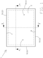
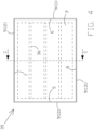
- Figures 1 to 3 show a tray 1 of the invention of the "baking" type, namely for baking breadsticks.
- Tray 1 preferably is substantially rectangular and comprises an at least partially wavy sheet 2.
- sheet 2 preferably is substantially shaped like a rectangle, preferably with the vertexes rounded, and is made of metal, preferably of AISI 304 steel.
- the cross section of sheet 2 includes a plurality of ridges 3 alternated by a plurality of depressions 4.
- the ridges 3 and the depressions 4 extend, as a whole, in a same direction, preferably parallel to two opposite sides, preferably the short ones, of the rectangle as sheet 2 is substantially shaped.
- the ridges 3 and the depressions 4 preferably extend vertically in Figure 1 .
- Sheet 2 is delimited by an edge comprising an opposite first stretch 5 and a second stretch 6, which are preferably mutually parallel, and more preferably corresponding to the short sides of the rectangle as sheet 2 is substantially shaped.
- the edge delimiting sheet 2 further comprises a third stretch 7 and a fourth stretch 8, they also opposite each other and each of which being interposed between the above-mentioned stretches 5 and 6.
- the stretches 7 and 8 are preferably mutually parallel, and more preferably corresponding to the long sides of the rectangle as sheet 2 is substantially shaped.
- the stretches 7 and 8, which are arranged horizontally in Figure 1 therefore are preferably orthogonal to the stretches 5 and 6, which are arranged vertically Figure 1 .
- the stretches 5 and 6 of the edge of sheet 2 extend in respective directions which preferably are parallel both to each other and to the direction in which the ridges 3 and the depressions 4 extend in sheet 2.
- the stretches 7 and 8 of the edge of sheet 2 extend in respective directions which preferably are parallel to each other and orthogonal to the direction in which the ridges 3 and the depressions 4 extend in sheet 2.
- sheet 2 is at least partially flat at the stretches 5 and 6 of the edge thereof, and includes the ridges 3 alternated by the depressions 4 at the stretches 7 and 8 of the edge thereof.
- the stretches 5 and 6 of the edge of sheet 2 preferably are coplanar.
- Frame 9 preferably comprises four preferably rectilinear tubular elements 10, 11, 12 and 13 connected to one another at the respective ends preferably so as to form, overall, a frame which is substantially shaped like the perimeter of a rectangle.
- a first tubular element 10 and a second tubular element 11 are opposite to each other, preferably mutually parallel, and more preferably corresponding to the short sides of the rectangle as the perimeter of which frame 9 is substantially shaped.
- a third element tubular 12 and a fourth tubular element 13 are also opposite to each other and each of them is interposed between the above-mentioned tubular elements 10 and 11.
- the tubular elements 12 and 13 are preferably mutually parallel and more preferably, corresponding to the long sides of the rectangle as the perimeter of which frame 9 is substantially shaped.
- the tubular elements 12 and 13 are therefore preferably orthogonal to the tubular elements 10 and 11.
- the tubular elements 10, 11, 12 and 13 lie on the same side as sheet 2. In particular, they lie below the latter in Figure 1 .
- the tubular elements 10 and 11 are preferably arranged so as to extend in respective directions which not only are parallel to each other but also to the direction in which the ridges 3 and the depressions 4 extend in sheet 2.
- the tubular elements 12 and 13 are preferably arranged so as to extend in respective directions which not only are parallel to each other but also orthogonal to the direction in which the ridges 3 and the depressions 4 extend in sheet 2.
- the tubular elements 10 and 11 are preferably arranged so as to extend in respective directions which are parallel to the directions in which the stretches 5 and 6, respectively, of the edge of sheet 2 extend.
- the tubular elements 12 and 13 are preferably arranged so as to extend in respective directions which are parallel to the directions in which the stretches 7 and 8, respectively, of the edge of sheet 2 extend.
- the rectangle as sheet 2 is substantially shaped has almost the same dimensions as the rectangle like which peripheral frame 9 is substantially shaped. More preferably, sheet 2 and frame 9 overlap each other and are mutually connected so that stretch 5 overlaps and is connected to the tubular element 10, stretch 6 overlaps and is connected to the tubular element 11, stretch 7 overlaps and is connected to the tubular element 12, stretch 8 overlaps and is connected to the tubular element 13, and the vertexes of the rectangle as sheet 2 is substantially shaped almost overlap the rectangle, respectively, like which peripheral frame 9 is substantially shaped.
- each of the tubular elements 10, 11, 12 and 13 has a preferably rectangular cross section. As shown in Figures 2 and 3 , each of the tubular elements 10, 11, 12 and 13 is preferably arranged with the short sides of the rectangle as the perimeter of which the cross section of said tubular element 10, 11, 12 or 13 is substantially shaped, which are parallel to the plane on which the stretches 5 and 6 of sheet 2 preferably lie. Each of the tubular elements 10, 11, 12 and 13 therefore is preferably arranged with the long sides of the rectangle as the perimeter of which the cross section of said tubular element 10, 11, 12 or 13 is substantially shaped, which are orthogonal to the plane on which the stretches 5 and 6 of sheet 2 preferably lie.
- each of the tubular elements 10, 11, 12 and 13 corresponding to the short side of the aforesaid rectangle (as the perimeter of which the cross section of said tubular element 10, 11, 12 or 13 is substantially shaped) closest to sheet 2 was previously indicated by the expression "first wall” and is marked by numeral 14 in the drawings.
- first wall the wall of each of the tubular elements 10, 11, 12 and 13 corresponding to the short side of the aforesaid rectangle (as the perimeter of which the cross section of said tubular element 10, 11, 12 or 13 is substantially shaped) closest to sheet 2 was previously indicated by the expression "first wall” and is marked by numeral 14 in the drawings.
- the tubular elements 10, 11, 12 and 13 are thus connected to one another so that the walls 14 - each of which is flat and extending in length - face sheet 2.
- sheet 2 at each of the stretches 5 and 6, is folded over itself, preferably in a "U", on the side of said tubular elements 10 and 11 (i.e. downwards in Figure 2 ), respectively, so as to comprise a flat upper strip 15 and a lower strip 16 which are at least partially mutually opposed at a given distance from each other.
- the assembly consisting of the strips 15 and 16 and of the fold mutually connecting them faces the assembly consisting of the strips 15 and 16 and the fold mutually connecting the other of said stretches 5 and 6 on the side of the concavity thereof.
- strip 15 and wall 14 of the tubular element on which said stretch 5 or 6 or edge is superimposed lie on opposite sides with respect to strip 16.
- tray 1 For each of the tubular elements 10 and 11, tray 1 comprises a metal bar 17, preferably made of AISI 304 steel and identified above by the expression "first bar”.
- Each bar (17) preferably has an "L” cross section.
- Each bar 17 therefore preferably comprises a flat wall 18, extending in length and identified above by the expression “second wall”, which is orthogonally connected, at an edge thereof, to the edge of a further wall 19, it also flat and extending in length.
- the arms of the aforesaid "L” of each bar 17 therefore correspond to the walls 18 and 19, respectively.
- Each of the walls 18 and 19 preferably is rectangular and the walls 18 and 19 in each bar 17 are preferably connected to each other by a fold at a long edge thereof.
- tray 1 comprises one of the bars 17 for each of the tubular elements 10 and 11.
- the corresponding bar 17 is connected to said tubular element 10 or 11 so that wall 18 at least partially opposes wall 14 of said tubular element 10 or 11 at a given distance from the latter.
- wall 19 of the corresponding bar 17 is connected to said tubular element 10 or 11 by means of one or more welds 21, preferably by electric spot welding, at a wall 20 of said tubular element 10 or 11 orthogonal to wall 14 of the latter and facing the other of said tubular elements 10 and 11 (i.e.
- wall 18 is preferably parallel to wall 14 of the tubular element 10 or 11 to which bar 17 to which wall 18 belongs, is connected.
- wall 19 is preferably parallel to and at least partially matches wall 20 of the tubular element 10 or 11 to which bar 17 to which wall 19 belongs, is connected.
- the walls 18 and 19 of each bar 17 have a length (intended as dimension in the direction in which bar 17 extends) which is preferably almost equal to the one of the tubular element 10 or 11 to which said bar 17 is connected.
- the walls 18 and 19 of each bar 17 further have a width (intended as third dimension of said walls in addition to length and thickness) which is preferably less than the one of the walls 14 and 20 (of the tubular element 10 or 11 to which said bar 17 is connected), respectively, to which said walls 18 and 19 are opposed, respectively.
- the strip 16 of stretch 5 or 6 of the edge of sheet 2 overlapping said tubular element 10 or 11 is at least partially interposed between wall 14 of said tubular element 10 or 11 and the wall 18 of bar 17 connected to said tubular element 10 or 11 (so that the wall 18 of bar 17 connected to said tubular element 10 or 11 at least partially opposes wall 14 of said tubular element 10 or 11 with the at least partial interposition of the strip 16 of stretch 5 or 6 of the edge of sheet 2 overlapping said tubular element 10 or 11).
- the wall 18 of bar 17 connected to said tubular element 10 or 11 is also at least partially interposed between the strips 15 and 16 of stretch 5 or 6 of the edge of sheet 2 overlapping said tubular element 10 or 11 (so that the strips 15 and 16 of stretch 5 or 6 of the edge of sheet 2 overlapping said tubular element 10 or 11 are at least partially mutually opposed with the at least partial interposition of the wall 18 of bar 17 connected to said tubular element 10 or 11).
- the strip 16 of stretch 5 or 6 of the edge of sheet 2 overlapping said tubular element 10 or 11 is sandwiched between wall 14 of said tubular element 10 or 11 and the wall 18 of bar 17 connected to said tubular element 10 or 11. Additionally or alternatively, the wall 18 of bar 17 connected to said tubular element 10 or 11 is sandwiched between the strips 15 and 16 of stretch 5 or 6 of the overlapping edge of sheet 2 and said tubular element 10 or 11 so that sheet 2 is connected to the tubular elements 10 and 11.
- the bars 17, belonging to the previously mentioned "first connection means”, connect sheet 2, at the stretches 5 and 6 of the edge itself, to frame 9 at the tubular elements 10 and 11, respectively.
- tray 1 comprises a metal bar 25, preferably made of AISI 304 steel and identified above by the expression "second bar”.
- Each bar 25 has a cross section, which is preferably almost a "U” (i.e. almost like the symbol in the international phonetic alphabet of the "rounded almost rear almost closed vowel").
- each bar 25 preferably comprises four walls 26, 27, 28 and 29 (previously identified by the expressions "third wall”, “fourth wall”, “fifth wall” and “sixth wall”, respectively), each of which being flat and extending in length.
- the walls 26 and 29 are preferably coplanar and the walls 27 and 28 are preferably mutually parallel and at least partially opposed, at a given distance from each other.
- each of the walls 27 and 28 is also preferably orthogonal to the walls 26 and 29.
- the walls 27 and 28 are preferably connected to each other by at least one fold at an edge 30 thereof (identified above by the expression "first edge") so that the assembly consisting of the walls 27 and 28 and of the fold mutually connecting them has a concave cross section (corresponding to the bulge in the ).
- wall 27 is connected, at a second edge thereof opposite to edge 30 thereof, to wall 26, at an edge of the latter, by at least one fold.
- wall 28 is connected, at a second edge thereof opposite to edge 30 thereof, to wall 29, at an edge of the latter, by at least one fold.
- Each of the walls 26, 27, 28 and 29 preferably is rectangular and, in each bar 25, the walls 26, 27, 28 and 29 are preferably connected to one another by a fold at long edges thereof.
- tray 1 comprises one of the bars 25 for each of the tubular elements 12 and 13.
- the corresponding bar 25 is connected to said tubular element 12 and 13 so that the assembly consisting of the walls 27 and 28 and the fold mutually connecting them faces towards sheet 2 on the side of the concavity thereof.
- wall 26 of the corresponding bar 25 is connected to said tubular element 12 or 13 by means of one or more welds 22, preferably by electric spot welding, at wall 14 of said tubular element 12 or 13.
- the wall 29 of bar 25 connected to said tubular element 12 or 13 is connected by means of one or more welds 23, preferably by electric spot welding, to a portion of sheet 2 including stretch 7 or 8 of the edge thereof overlapping said tubular element 12 or 13, at one or more depressions 4, respectively, so that sheet 2 is connected to the tubular elements 12 and 13.
- the bars 25, belonging to the previously mentioned “second connection means”, connect sheet 2, at two portions of the latter including the stretches 7 and 8, respectively, of the edge itself, to frame 9 at the tubular elements 12 and 13, respectively.
- wall 27 is preferably parallel to wall of the tubular element 12 or 13 to which bar 25 to which wall 27 belongs is connected, previously indicated by reference numeral 20, i.e. the wall of said tubular element 12 or 13 orthogonal to wall 14 of the latter and facing the other of said tubular elements 12 and 13 (i.e. at a wall of said tubular element 12 or 13 corresponding to a side of the rectangle as the perimeter of which the cross section of said tubular element 12 or 13 is substantially shaped, orthogonal to the side of said rectangle corresponding to wall 14 of said tubular element 12 or 13). More preferably, in each bar 25, wall 27 is preferably in contact with wall 20 of the tubular element 12 or 13 to which bar 25 to which wall 27 belongs is connected, and even more preferably, so as to at least partially match with the latter.
- each bar 25 has a length (intended as dimension in the direction in which bar 25 extends) which is preferably almost equal to the one of the tubular element 12 or 13 to which said bar 25 is connected.
- the walls 27 and 28 of each bar 25 further have a width (intended as third dimension of said walls in addition to length and thickness), which is preferably less than the one of wall 20 (of the tubular element 12 or 13 to which said bar 25 is connected), to which wall 27 is preferably opposed.
- the connection between sheet 2 and frame 9 is such as to allow these two components to thermally expand without generating stresses resulting in a disconnection of sheet 2 from frame 9 or cracking of sheet 2 with the use of tray 1.
- the strips 16 of the stretches 5 and 6 of the edge of sheet 2 in conjunction with the strips 15, wall 18 of the bars 17, may indeed slide, in conjunction with the strips 15, with respect to frame 9.
- the aforesaid portions of sheet 2 including the stretches 7 and 8, respectively, of the edge of sheet 2 may move away from or close to the tubular elements 12 and 13, respectively, thus elastically deforming the folds between the walls 26, 27, 28 and 29 of the bars 25.
- said freedom of movement is sufficient to at least partially compensate for the differences in thermal expansion between sheet 2 and frame 9.
- Figures 4 and 5 show a tray 35 which differs from tray 1 in that frame 9 also comprises one or more metal bars 36 preferably made of AISI 304 steel.
- Each of the bars 36 identified above by the expression “third bars”, includes a first end and a second end, opposite to said first end.
- Each of the bars 36 is interposed between the tubular elements 10 and 11 so that, in each bar 36, the first end is closer to the tubular element 10 than the tubular element 11, and the second end is closer to the tubular element 11 than the tubular element 10.
- Each of the bars 36 preferably extends from the tubular element 10 to the tubular element 11, more preferably at a given distance from the latter.
- one or more bars 36 could be connected to the tubular element 10 at the first end thereof, and to the tubular element 11 at the second end thereof.
- the bars 36 are preferably arranged so that the directions in which the bars 36 extend, respectively, are mutually parallel and orthogonal to the directions in which the tubular elements 10 and 11 extend, respectively (and therefore preferably orthogonal to the direction in which the ridges 3 and the depressions 4 extend in sheet 2).
- Each bar 36 preferably has an almost “ ⁇ " cross section (i.e. "lower case omega”).
- each bar 36 preferably comprises six walls 37, 38, 39, 40, 41 and 42 (previously identified by the expressions “seventh wall”, “eighth wall”, “eleventh wall” “twelfth wall”, “ninth wall” and “tenth wall”, respectively), each of which being flat and extending in length.
- the walls 37 and 42 are preferably coplanar, and the walls 38, 39, 40 and 41 are preferably mutually parallel and at least partially opposed to one another, mutually spaced apart.
- each of the walls 38, 39, 40 and 41 is also preferably orthogonal to the walls 37 and 42.
- the walls 39 and 40 are preferably connected to each other by at least one fold at an edge 45 thereof (identified above by the expression "first edge") so that the assembly consisting of the walls 39 and 40 and the fold mutually connecting them has a concave cross section.
- wall 39 is connected, at a second edge 43 thereof opposite to edge 45 thereof, to wall 38, at an edge of the latter, by at least one fold.
- wall 40 is connected, at a second edge 44 thereof opposite to edge 45 thereof, to wall 41, at an edge of the latter, by at least one fold.
- each bar 36 wall 38 is connected, at an edge thereof opposite to edge 43 thereof, to wall 37, at an edge of the latter, by at least one fold.
- wall 41 is connected, at an edge thereof opposite to edge 44 thereof, to wall 42, at an edge of the latter, by at least one fold.
- Each of the walls 37, 38, 39, 40, 41 and 42 preferably is rectangular and, in each bar 36, the walls 37, 38, 39, 40, 41 and 42 are preferably connected to one another by a fold at long edges thereof.
- connection is preferably obtained by means of welds, preferably by electric spot welding, between each of the tubular elements 10 and 11 and the two ends, respectively, of said bar 36, more preferably at the fold mutually joining the walls 38 and 39 and/or at the fold mutually joining the walls 40 and 41.
- Each bar 36 is connected to sheet 2 so that the assembly consisting of the walls 39 and 40 and the fold mutually connecting them faces towards sheet 2 on the side of the convexity thereof.
- each bar 36 at both wall 37 and wall 42, is connected by means of one or more welds 31, preferably of the TIG type with the addition of material, to sheet 2 at one or more depressions 4, respectively, so that sheet 2 is connected to said bar 36.
- each bar 36 further have a width (intended as third dimension of said walls in addition to length and thickness) which is preferably less than the one of the walls 38 and 41 between which they are interposed, so as not to be in contact with sheet 2 (at edge 45).
- the bars 36 serve as reinforcing bars of frame 9 and, like the bars 17 and 25, are shaped and connected to sheet 2 so as to allow the latter and frame 9 to thermally expand without generating stresses resulting in a disconnection of sheet 2 from the frame 9 or cracking of sheet 2, with the use of tray 35.
- the bars 36 have a length which is preferably less than the distance between the tubular elements 10 and 11 in order to allow the latter to thermally expand by bending towards the inside of frame 9 (i.e. one approaching the other).
- the bars 36 are substantially shaped as the bars 25. According to this variant, the bars 36 no not have the walls 39 and 40.
- the walls 38 and 41 of each bar therefore are not connected to one another by two walls and three folds, rather by one fold alone.
- each bar 36 is connected to sheet 2 so that the assembly consisting of the walls 38 and 41 and the fold mutually connecting them faces towards sheet 2 on the side of the concavity thereof.
- the walls 38 and 41 are at least partially mutually opposed with the at least partial interposition of the walls 39 and 40.
Landscapes
- Life Sciences & Earth Sciences (AREA)
- Engineering & Computer Science (AREA)
- Food Science & Technology (AREA)
- Rigid Containers With Two Or More Constituent Elements (AREA)
- Baking, Grill, Roasting (AREA)
- Table Equipment (AREA)
- Bakery Products And Manufacturing Methods Therefor (AREA)
Claims (10)
- Backblech (1, 35) zum Backen von Grissini, umfassend:• ein zumindest teilweise gewelltes Metallblech (2), wobei das Blech (2) einen Querschnitt mit einer Vielzahl von Stegen (3) aufweist, die sich durch eine Vielzahl von Vertiefungen (4) abwechseln,wobei sich die Stege (3) und die Vertiefungen (4) als Ganzes im Blech (2) in die gleiche Richtung erstrecken,wobei das Blech (2) durch eine Kante begrenzt ist, die einen ersten und einen zweiten Abschnitt (5, 6) aufweist, die einander gegenüberliegen,wobei die Kante weiterhin einen dritten und vierten Abschnitt (7, 8) aufweist, die einander gegenüberliegen und jeweils zwischen dem ersten und zweiten Abschnitt (5, 6) liegen,wobei das Blech (2):- zumindest teilweise eben bei den ersten und zweiten Abschnitten (5, 6) der Kante ist,
und- die Stege (3) aufweist, die sich von den Vertiefungen (4) bei den dritten und vierten Abschnitten (7, 8) der Kante abwechseln;• einen Rahmen (9) zur Unterstützung des Bleches (2), wobei der Rahmen (9) eine Vielzahl von rohrförmigen Metallelementen (10, 11, 12, 13) aufweist,wobei jedes der rohrförmigen Elemente (10, 11, 12, 13) eine erste ebene Wand (14) aufweist, die sich in der Länge erstreckt,wobei sich die rohrförmigen Elemente (10, 11, 12, 13) auf derselben Seite wie das Blech (2) befinden und so miteinander verbunden sind, dass die ersten Wände (14) dem Blech (2) zugewandt sind,wobei ein erstes und zweites rohrförmiges Element (10, 11) der Vielzahl einander gegenüberliegen,wobei ein drittes und viertes rohrförmiges Element (12, 13) der Vielzahl einander gegenüberliegen,wobei jedes der dritten und vierten rohrförmigen Elemente (12, 13) zwischen den ersten und zweiten rohrförmigen Elementen (10, 11) angeordnet ist;• erste Verbindungsmittel (17) des Bleches (2) an den ersten und zweiten Abschnitten (5, 6) der Kante, mit dem Rahmen (9) an den jeweiligen ersten und zweiten rohrförmigen Elementen (10, 11);• zweite Verbindungsmittel (25) des Bleches (2) an zwei Teilen des letzeren, die jeweils den dritten und vierten Abschnitt (7, 8) der Kante, mit dem Rahmen (9) bei den dritten und vierten rohrförmigen Element (12, 13), umfassen,
wobei das Backblech (1, 35) weiterhin wobei:• das Blech (2) bei jedem der ersten und zweiten Abschnitte (5, 6) der Kante auf der Seite der rohrförmigen Elemente (10, 11, 12, 13) in sich selbst derart zurückgefaltet ist, dass es einen oberen ebenen Streifen (15) und einen unteren Streifen (16) aufweist, die einander zumindest teilweise in einem gegebenen Abstand voneinander gegenüberliegen,wobei für jeden der ersten und zweiten Abschnitte (5, 6) der Kante, der obere Streifen (15) und die erste Wand (14) des ersten oder zweiten rohrförmigen Elements (10, 11), mit dem der Abschnitt (5, 6) durch die ersten Verbindungsmittel (17) verbunden ist, auf gegenüberliegenden Seiten mit Bezug auf den unteren Streifen (16), liegen,wobei für jeden der ersten und zweiten Abschnitte (5, 6) der Kante, die Anordnung bestehend aus dem oberen Streifen (15), dem unteren Streifen (16) und einer miteinander verbundenen Falte dieser durch den oberen Streifen (15) gebildeten Anordnung zugewandt ist,wobei der untere Streifen (16) und eine die miteinander verbindende Falte des anderen ersten oder zweiten Abschnitts (5, 6) der Kante auf der Seite seiner Konkavität liegt;• wobei die ersten Verbindungsmittel (17) für jedes der ersten und zweiten rohrförmigen Elemente (10, 11) eine erste Metallstange (17) mit mindestens einer zweiten ebenen Wand (18) umfassen, die sich in der Länge erstreckt;wobei für jedes dieser ersten und zweiten rohrförmigen Elemente (10, 11):- der untere Streifen (16) des ersten oder zweiten Abschnitts (5, 6) der Kante, mit dem das erste oder zweite rohrförmige Element (10, 11) durch die ersten Verbindungsmittel (17) zumindest teilweise verbunden ist:> zwischen der ersten Wand (14) des ersten oder zweiten rohrförmigen Elements (10, 11)
und> zwischen der zweiten Wand (18) der ersten Stange (17), die mit dem ersten oder zweiten rohrförmigen Element (10, 11) verbunden ist, angeordnet ist,so dass die zweite Wand (18) der ersten Stange (17), die mit dem ersten oder zweiten rohrförmigen Element (10, 11) verbunden ist, zumindest teilweise der ersten Wand (14) des ersten oder zweiten rohrförmigen Elements (10, 11) mit der zumindest teilweiser Zwischenlage des unteren Streifens (16) des ersten oder zweiten Abschnitts (5, 6) der Kante gegenüberliegt, mit dem das erste oder zweite rohrförmige Element (10, 11) durch die ersten Verbindungsmittel (17) verbunden ist,
und- wobei die zweite Wand (18) der ersten Stange (17), die mit dem ersten oder zweiten rohrförmigen Element (10, 11) verbunden ist, zumindest teilweise zwischen dem oberen Streifen (15) und dem unteren Streifen (16) des ersten oder zweiten Abschnitts (5, 6) der Kante liegt, an den das erste oder zweite rohrförmige Element (10, 11) mit den ersten Verbindungsmitteln (17) verbunden ist,
so dass der obere Streifen (15) und der untere Streifen (16) des ersten oder zweiten Abschnitts (5, 6) der Kante, mit dem das erste oder zweite rohrförmige Element (10, 11) durch die ersten Verbindungsmittel (17) verbunden ist, zumindest teilweise einander gegenüberliegen, wobei zumindest teilweise dazwischen die zweite Wand (18) der ersten Stange (17), die mit dem ersten oder zweiten rohrförmigen Element (10, 11) verbunden ist, liegtwobei außerdem, für jedes der ersten und zweiten rohrförmigen Elemente (10, 11):- der untere Streifen (16) des ersten oder zweiten Abschnitts (5, 6) der Kante, mit dem das erste oder zweite röhrenförmige Element (10, 11) durch das erste Verbindungsmittel (17) verbunden sind:> zwischen der ersten Wand (14) des ersten oder zweiten rohrförmigen Elements (10, 11)
und> der zweiten Wand (18) der ersten Stange (17), die mit dem ersten oder zweiten rohrförmigen Element (10, 11) verbunden ist, sandwichartig angeordnet ist,
und/oder- die zweite Wand (18) der ersten Stange (17), die mit der ersten oder zweiten rohrförmigen Element (10, 11) verbunden ist, zwischen dem oberen Streifen (15) und dem unteren Streifen (16) des ersten oder zweiten Abschnitts (5, 6) der Kante, mit der das erste oder zweite rohrförmige Element (10, 11) verbunden ist, durch das erste Verbindungsmittel (17) sandwichartig angeordnet ist,
so dass das Blech (2) mit dem ersten oder zweiten rohrförmigen Element (10, 11) verbunden ist;• die zweiten Verbindungsmittel (25) für jedes der dritten und vierten rohrförmigen Elemente (12, 13) eine zweite Metallstange (25) aufweisen, die mindestens eine dritte, vierte, fünfte und sechste Wand (26, 27, 28, 29) umfassen, die jeweils eben sind und sich in der Länge erstrecken,dadurch gekennzeichnet, dass für jedes der ersten und zweiten rohrförmigen Elemente (10, 11) ist die erste Stange (25), die an dem ersten oder zweiten rohrförmigen Element (10, 11) mittels einer oder mehreren Schweißungen (21) verbunden ist, wobei die zweite Wand (18) zumindest teilweise der ersten Wand (14) des ersten oder zweiten rohrförmigen Elemente (10, 11) mit einem gewissen Abstand aus dem letzeren, gegenüberliegt,wobei für jeden des dritten und vierten rohrförmigen Elemente (12, 13) die zweite Stange (25) auf der dritten Wand (26) durch eine oder mehrere Schweißungen (22) mit dem dritten oder vierten rohrförmigen Element (12, 13) an dessen erster Wand (14), verbunden ist wobei in jeder der zweiten Stangen (25):- die vierte und fünfte Wand (27, 28) liegen sich zumindest teilweise gegenüber und sind durch zumindest eine Falte an einer ersten Kante (30) davon miteinander verbunden;- die vierte Wand (27) an einer zweiten Kante davon gegenüber der ersten Kante (30) davon durch mindestens eine Falte mit der dritten Wand (26) an einer Kante davon verbunden ist;- die vierte Wand (27) mit der dritten Wand (26) so verbunden ist, dass die aus der vierten und fünften Wand (27, 28) und der sie verbindenden Falte gebildete Anordnung der Seite der Bleches (2) auf der Konkavität davon, zugewandt ist;- wobei die fünfte Wand (28) an einer zweiten Kante davon, die der ersten Kante davon gegenüberliegt, mit der sechsten Wand (29) an einer Kante der letzteren durch jeweils mindestens eine Falte für jeden der dritten und vierten rohrförmigen Elemente (12, 13), verbunden ist, wobei die zweite Stange (25) an der sechsten Wand (29) mittels einer oder mehrerer Schweißungen (23) an den Abschnitt des Bleches (2), einschließlich des dritten oder vierten Abschnitts (7, 8) der Kante, an den das dritte oder vierte rohrförmige Element (12, 13) angeschlossen ist, durch das zweite Verbindungsmittel (25) jeweils an einer oder mehreren der Vertiefungen (4) angeschlossen ist, so dass das Blech (2) mit dem dritten oder vierten rohrförmigen Element (12, 13) verbunden ist. - Backblech (1, 35) nach Anspruch 1, dadurch gekennzeichnet, dass jedes der ersten und zweiten rohrförmigen Elemente (10, 11) einen rechteckförmigen Querschnitt aufweist, wobei eine Seite des Rechtecks der ersten Wand (14) des ersten oder zweiten rohrförmigen Elements (10, 11) entspricht,
wobei für jedes der ersten und zweiten rohrförmigen Elemente (10, 11), die erste Stange (17) der ersten Verbindungsmittel des ersten oder zweiten rohrförmigen Elements (10, 11):• einen "L"-förmigen Querschnitt mit einem Arm des L aufweist, der der zweiten Wand (18) der ersten Stange (17) entspricht,• durch eine oder mehrere Schweißungen (21) an einer Wand (19), die dem anderen Arm des L entspricht, mit dem ersten oder zweiten rohrförmigen Element (10, 11) an einer Wand (20) des letzteren verbunden ist, die einer Seite des Rechtecks entspricht, die orthogonal zu der Seite ist, die der ersten Wand (14) des ersten oder zweiten rohrförmigen Elements (10, 11) entspricht. - Backblech (1, 35) nach einem der vorhergehenden Ansprüche, dadurch gekennzeichnet, dass sich die ersten und zweiten rohrförmigen Elemente (10, 11) und die ersten und zweiten Abschnitte (5, 6) der Kante des Blechs (2) in jeweils parallelen Richtungen sowohl zueinander als auch zu der Richtung sich erstrecken, in der sich die Stege (3) und die Vertiefungen (4) im Blech (2) erstrecken.
- backblech (1, 35) nach einem der vorhergehenden Ansprüche, dadurch gekennzeichnet, dass in jedem der zweiten Stangen (25):• sind die dritte und sechste Wand (26, 29) koplanar,• sind die vierte und fünfte Wand (27, 28) parallel zueinander
und• ist jede der vierten und fünften Wände (27, 28) orthogonal zu der dritten und sechsten Wand (26, 29). - Backblech (1, 35) nach Anspruch 4, dadurch gekennzeichnet, dass jedes der dritten und vierten rohrförmigen Elemente (12, 13) einen rechteckförmigen Querschnitt aufweist, wobei eine Seite des Rechtecks der ersten Wand (14) des dritten oder vierten Rohrelement (12, 13) entspricht,
wobei für jedes der dritten und vierten Rohrelemente (12, 13) die vierte Wand (27) der zweiten Stange (25) des zweiten Verbindungsmittels des dritten oder vierten Rohrelements (12, 13) parallel zu einer Wand (20) des letzteren ist, die einer Seite des Rechtecks entspricht, die orthogonal zu der Seite ist, die der ersten Wand (14) des dritten oder vierten rohrförmigen Elements (12, 13) entspricht. - Backblech (1, 35) nach Anspruch 5, dadurch gekennzeichnet, dass für jedes der dritten und vierten Rohrelemente (12, 13) steht die vierte Wand (27) der zweiten Stange (25) des zweiten Verbindungsmittels des dritten oder vierten rohrförmigen Element (12, 13) in Kontakt mit der Wand (20) des letzteren, die der Seite des Rechtecks entspricht, die orthogonal zu der Seite ist, die der ersten Wand (14) des dritten oder vierten rohrförmigen Elements (12, 13) entspricht.
- Backblech (1, 35) nach einem der vorhergehenden Ansprüche, dadurch gekennzeichnet, dass sich die dritten und vierten Rohrelemente (12, 13) und die dritten und vierten Abschnitte (12, 13) der Kante des Blechs (2) in jeweiligen Richtungen parallel zueinander und orthogonal zu der Richtung erstrecken, in der sich die Stege (3) und die Vertiefungen (4) im Blech (2) erstrecken.
- Backblech (35) nach einem der vorhergehenden Ansprüche, dadurch gekennzeichnet, dass der Rahmen (9) eine oder mehrere dritte Metallstangen (36) umfasst, die jeweils zwischen den ersten und zweiten rohrförmigen Elementen (10, 11) angeordnet sind,wobei jede der dritten Stangen (36) mindestens eine siebte, achte, neunte und zehnte Wand (37, 38, 41, 42) umfasst, von denen jede eben ist und sich in der Länge erstreckt,wobei jede der dritten Stangen (36) bei der siebten Wand (37) und der zehnten Wand (42) mittels einer oder mehrerer Schweißungen (31) mit dem Blech (2) bei einer oder mehrerer Vertiefungen (4) derart verbunden ist, dass das Blech (2) mit der dritten Stange (36) verbunden ist,wobei in jeder der dritten Stangen (36):• die achte und neunte Wand (38, 41) zumindest teilweise einander gegenüberliegen und durch zumindest eine Falte an einer ersten Kante davon miteinander verbunden sind;• die achte Wand (38) an einer zweiten Kante davon gegenüber der ersten Kante davon mit der siebten Wand (3) an einer Kante der letzteren durch mindestens eine Falte verbunden ist;• wobei die achte Wand (38) mit der siebten Wand (37) so verbunden ist, dass die durch die achte und neunte Wand (38, 41) und durch die sie gegenseitig verbindende Falte gebildete Anordnung dem Blech (2) auf ihrer Seite seiner Konkavität zugewandt ist;• wobei die neunte Wand (41) an einer zweiten Kante davon, die der ersten Kante davon gegenüberliegt, mit der zehnten Wand (42) an einer Kante der letzteren durch mindestens eine Falte verbunden ist.
- Backblech (35) nach Anspruch 8, dadurch gekennzeichnet, dass jeder der dritten Stangen (36) mindestens eine elfte und zwölfte Wand (39, 40) aufweist, die jeweils eben sind und sich in der Länge erstrecken,
wobei in jeder der dritten Stangen (37):• die elften und zwölften Wände (39, 40) zumindest teilweise einander gegenüberliegen und durch zumindest eine Falte an einer ersten Kante (45) davon miteinander verbunden sind;• wobei die elfte Wand (39) an einer zweiten Kante (43) davon, die der ersten Kante (45) davon gegenüberliegt, mit der achten Wand (38) an deren ersten Kante durch mindestens eine Falte verbunden ist;• wobei die elfte Wand (39) mit der achten Wand (38) so verbunden ist, dass die aus der elften und zwölften Wand (39, 40) und aus der sie miteinander verbindenden Falte gebildete Anordnung dem Blech (2) auf der Seite ihrer Konvexität zugewandt ist;• wobei die zwölfte Wand (40) an einer zweiten Kante (44) davon, die der ersten Kante (45) gegenüberliegt, mit der neunten Wand (41) an deren ersten Kante durch mindestens eine Falte verbunden ist,so dass in jedem der dritten Stangen (37) liegen die achten und neunten Wände (38, 41) zumindest teilweise einander gegenüber, wobei die elfte und zwölfte Wand (39, 40) zumindest teilweise dazwischen liegt. - Backblech (35) nach Anspruch 8 oder 9, dadurch gekennzeichnet, dass sich die dritten Stangen (37) in jeweiligen Richtungen parallel zueinander und orthogonal zu der Richtung erstrecken, in die sich die Stege (3) und die Vertiefungen (4) im Blech (2) erstrecken.
Applications Claiming Priority (2)
| Application Number | Priority Date | Filing Date | Title |
|---|---|---|---|
| IT102020000031784A IT202000031784A1 (it) | 2020-12-22 | 2020-12-22 | Teglia da forno per la cottura di grissini con sistema di compensazione delle differenze di dilatazione termica dei propri componenti |
| PCT/IT2021/050090 WO2022137266A1 (en) | 2020-12-22 | 2021-03-30 | Baking tray for baking breadsticks with a system for compensating for the differences in thermal expansion of the components thereof |
Publications (3)
| Publication Number | Publication Date |
|---|---|
| EP4181682A1 EP4181682A1 (de) | 2023-05-24 |
| EP4181682C0 EP4181682C0 (de) | 2024-04-24 |
| EP4181682B1 true EP4181682B1 (de) | 2024-04-24 |
Family
ID=74875089
Family Applications (1)
| Application Number | Title | Priority Date | Filing Date |
|---|---|---|---|
| EP21722312.2A Active EP4181682B1 (de) | 2020-12-22 | 2021-03-30 | Backblech zum backen von brotstangen mit einem system zum ausgleich der unterschiedlichen wärmeausdehnung seiner bestandteile |
Country Status (4)
| Country | Link |
|---|---|
| EP (1) | EP4181682B1 (de) |
| ES (1) | ES2980851T3 (de) |
| IT (1) | IT202000031784A1 (de) |
| WO (1) | WO2022137266A1 (de) |
Citations (1)
| Publication number | Priority date | Publication date | Assignee | Title |
|---|---|---|---|---|
| EP2014171B1 (de) * | 2007-07-13 | 2010-09-29 | Anneliese Mertes GmbH | Backblech |
Family Cites Families (7)
| Publication number | Priority date | Publication date | Assignee | Title |
|---|---|---|---|---|
| ES287146Y (es) * | 1985-05-30 | 1986-07-01 | Achil,S.A. | Bandeja para hornos de panificacion perfeccionada |
| ES2171100B1 (es) * | 1999-08-13 | 2003-10-16 | Talleres Caselli S A | Dispositivo para la sujecion de las bandejas utilizdas en la coccion de pan. |
| EP2055190A1 (de) * | 2007-11-02 | 2009-05-06 | Carpinteria Metalica Bengolea, S.L. | Gargutträger |
| ITVR20090182A1 (it) * | 2009-10-29 | 2011-04-30 | Atrepan Srl | Sistema di assemblaggio della cornice su teglie per la cottura di prodotti da forno |
| DE202010007826U1 (de) * | 2010-06-10 | 2010-08-26 | Kempf, Marie-Luise | Backblech für Backöfen, insbesondere für industriell betriebene Backanlagen |
| DE202010007825U1 (de) * | 2010-06-10 | 2010-08-26 | Kempf, Marie-Luise | Backblech für Backöfen, insbesondere für industriell betriebene Backanlagen |
| ES2708701T3 (es) * | 2012-09-14 | 2019-04-10 | Jason Tingley | Bandeja para horno con insertos de horno intercambiables |
-
2020
- 2020-12-22 IT IT102020000031784A patent/IT202000031784A1/it unknown
-
2021
- 2021-03-30 WO PCT/IT2021/050090 patent/WO2022137266A1/en not_active Ceased
- 2021-03-30 ES ES21722312T patent/ES2980851T3/es active Active
- 2021-03-30 EP EP21722312.2A patent/EP4181682B1/de active Active
Patent Citations (1)
| Publication number | Priority date | Publication date | Assignee | Title |
|---|---|---|---|---|
| EP2014171B1 (de) * | 2007-07-13 | 2010-09-29 | Anneliese Mertes GmbH | Backblech |
Also Published As
| Publication number | Publication date |
|---|---|
| EP4181682C0 (de) | 2024-04-24 |
| ES2980851T3 (es) | 2024-10-03 |
| EP4181682A1 (de) | 2023-05-24 |
| WO2022137266A1 (en) | 2022-06-30 |
| IT202000031784A1 (it) | 2022-06-22 |
Similar Documents
| Publication | Publication Date | Title |
|---|---|---|
| JP3337222B2 (ja) | 複合パネルの成形 | |
| AU756037B2 (en) | Corrugated multilayer metal foil insulation panels and methods of making | |
| US4661677A (en) | Deep penetration laser welding of sheet metal | |
| US11091014B2 (en) | Housing assembly for electrical storage | |
| EP1946685B1 (de) | Grillplatte | |
| JPH11152061A (ja) | 商用車の支持フレームのための、好ましくは、u字状の、異形支持部材、特に、フレームの縦方向支持部材およびその製造法 | |
| US5692431A (en) | Bread baking | |
| NO331926B1 (no) | Profilert skinne og fremgangsmate for fremstilling av en profilert skinne | |
| EP4181682B1 (de) | Backblech zum backen von brotstangen mit einem system zum ausgleich der unterschiedlichen wärmeausdehnung seiner bestandteile | |
| EP4280881B1 (de) | Flaches backblech zum backen von lebensmitteln mit einem system zum ausgleich der unterschiedlichen wärmeausdehnung seiner bestandteile | |
| EP1801530B1 (de) | Verfahren und Vorrichtung zur Abbau thermischer Belastung in einem Wärmetauscherkern | |
| US6196119B1 (en) | Deep fat fryer | |
| JP2014080062A (ja) | 異種金属部材の接合構造 | |
| CN101018999A (zh) | 用于散热器的侧板 | |
| US20140216438A1 (en) | Home appliance with improved oven rack | |
| US6743008B2 (en) | Set of baking moulds for food products | |
| EP4006429B1 (de) | Ein kochgerät mit einer flexiblen halterung | |
| US5221917A (en) | Resistor ribbon for resistor grids | |
| US3000088A (en) | Method of making hollow rigid sheet metal structure | |
| US9308848B2 (en) | Backrest part for a seat, in particular a vehicle seat | |
| KR100491510B1 (ko) | 서로평행한다수의비증발성게터요소를지지하는단일편의프레임워크를갖춘게터펌프 | |
| EP4552876A1 (de) | Stossdämpfendes element für eine fahrzeugtür, fahrzeugtür, rohling und verfahren zur herstellung eines stossdämpfenden elements für eine fahrzeugtür | |
| US2734117A (en) | randall | |
| EP2146170B1 (de) | Heizkörperelement und Heizkörperblock | |
| JP3981700B2 (ja) | レトルト殺菌用トレー |
Legal Events
| Date | Code | Title | Description |
|---|---|---|---|
| STAA | Information on the status of an ep patent application or granted ep patent |
Free format text: STATUS: UNKNOWN |
|
| STAA | Information on the status of an ep patent application or granted ep patent |
Free format text: STATUS: THE INTERNATIONAL PUBLICATION HAS BEEN MADE |
|
| PUAI | Public reference made under article 153(3) epc to a published international application that has entered the european phase |
Free format text: ORIGINAL CODE: 0009012 |
|
| STAA | Information on the status of an ep patent application or granted ep patent |
Free format text: STATUS: REQUEST FOR EXAMINATION WAS MADE |
|
| 17P | Request for examination filed |
Effective date: 20230214 |
|
| AK | Designated contracting states |
Kind code of ref document: A1 Designated state(s): AL AT BE BG CH CY CZ DE DK EE ES FI FR GB GR HR HU IE IS IT LI LT LU LV MC MK MT NL NO PL PT RO RS SE SI SK SM TR |
|
| DAV | Request for validation of the european patent (deleted) | ||
| DAX | Request for extension of the european patent (deleted) | ||
| GRAP | Despatch of communication of intention to grant a patent |
Free format text: ORIGINAL CODE: EPIDOSNIGR1 |
|
| STAA | Information on the status of an ep patent application or granted ep patent |
Free format text: STATUS: GRANT OF PATENT IS INTENDED |
|
| INTG | Intention to grant announced |
Effective date: 20231124 |
|
| GRAS | Grant fee paid |
Free format text: ORIGINAL CODE: EPIDOSNIGR3 |
|
| GRAA | (expected) grant |
Free format text: ORIGINAL CODE: 0009210 |
|
| STAA | Information on the status of an ep patent application or granted ep patent |
Free format text: STATUS: THE PATENT HAS BEEN GRANTED |
|
| AK | Designated contracting states |
Kind code of ref document: B1 Designated state(s): AL AT BE BG CH CY CZ DE DK EE ES FI FR GB GR HR HU IE IS IT LI LT LU LV MC MK MT NL NO PL PT RO RS SE SI SK SM TR |
|
| REG | Reference to a national code |
Ref country code: GB Ref legal event code: FG4D |
|
| REG | Reference to a national code |
Ref country code: CH Ref legal event code: EP |
|
| REG | Reference to a national code |
Ref country code: DE Ref legal event code: R096 Ref document number: 602021012304 Country of ref document: DE |
|
| REG | Reference to a national code |
Ref country code: IE Ref legal event code: FG4D |
|
| U01 | Request for unitary effect filed |
Effective date: 20240429 |
|
| U07 | Unitary effect registered |
Designated state(s): AT BE BG DE DK EE FI FR IT LT LU LV MT NL PT SE SI Effective date: 20240514 |
|
| REG | Reference to a national code |
Ref country code: ES Ref legal event code: FG2A Ref document number: 2980851 Country of ref document: ES Kind code of ref document: T3 Effective date: 20241003 |
|
| PG25 | Lapsed in a contracting state [announced via postgrant information from national office to epo] |
Ref country code: IS Free format text: LAPSE BECAUSE OF FAILURE TO SUBMIT A TRANSLATION OF THE DESCRIPTION OR TO PAY THE FEE WITHIN THE PRESCRIBED TIME-LIMIT Effective date: 20240824 |
|
| PG25 | Lapsed in a contracting state [announced via postgrant information from national office to epo] |
Ref country code: HR Free format text: LAPSE BECAUSE OF FAILURE TO SUBMIT A TRANSLATION OF THE DESCRIPTION OR TO PAY THE FEE WITHIN THE PRESCRIBED TIME-LIMIT Effective date: 20240424 |
|
| PG25 | Lapsed in a contracting state [announced via postgrant information from national office to epo] |
Ref country code: GR Free format text: LAPSE BECAUSE OF FAILURE TO SUBMIT A TRANSLATION OF THE DESCRIPTION OR TO PAY THE FEE WITHIN THE PRESCRIBED TIME-LIMIT Effective date: 20240725 |
|
| PG25 | Lapsed in a contracting state [announced via postgrant information from national office to epo] |
Ref country code: PL Free format text: LAPSE BECAUSE OF FAILURE TO SUBMIT A TRANSLATION OF THE DESCRIPTION OR TO PAY THE FEE WITHIN THE PRESCRIBED TIME-LIMIT Effective date: 20240424 |
|
| PG25 | Lapsed in a contracting state [announced via postgrant information from national office to epo] |
Ref country code: PL Free format text: LAPSE BECAUSE OF FAILURE TO SUBMIT A TRANSLATION OF THE DESCRIPTION OR TO PAY THE FEE WITHIN THE PRESCRIBED TIME-LIMIT Effective date: 20240424 Ref country code: NO Free format text: LAPSE BECAUSE OF FAILURE TO SUBMIT A TRANSLATION OF THE DESCRIPTION OR TO PAY THE FEE WITHIN THE PRESCRIBED TIME-LIMIT Effective date: 20240724 Ref country code: IS Free format text: LAPSE BECAUSE OF FAILURE TO SUBMIT A TRANSLATION OF THE DESCRIPTION OR TO PAY THE FEE WITHIN THE PRESCRIBED TIME-LIMIT Effective date: 20240824 Ref country code: HR Free format text: LAPSE BECAUSE OF FAILURE TO SUBMIT A TRANSLATION OF THE DESCRIPTION OR TO PAY THE FEE WITHIN THE PRESCRIBED TIME-LIMIT Effective date: 20240424 Ref country code: GR Free format text: LAPSE BECAUSE OF FAILURE TO SUBMIT A TRANSLATION OF THE DESCRIPTION OR TO PAY THE FEE WITHIN THE PRESCRIBED TIME-LIMIT Effective date: 20240725 Ref country code: RS Free format text: LAPSE BECAUSE OF FAILURE TO SUBMIT A TRANSLATION OF THE DESCRIPTION OR TO PAY THE FEE WITHIN THE PRESCRIBED TIME-LIMIT Effective date: 20240724 |
|
| PG25 | Lapsed in a contracting state [announced via postgrant information from national office to epo] |
Ref country code: CZ Free format text: LAPSE BECAUSE OF FAILURE TO SUBMIT A TRANSLATION OF THE DESCRIPTION OR TO PAY THE FEE WITHIN THE PRESCRIBED TIME-LIMIT Effective date: 20240424 |
|
| PG25 | Lapsed in a contracting state [announced via postgrant information from national office to epo] |
Ref country code: SK Free format text: LAPSE BECAUSE OF FAILURE TO SUBMIT A TRANSLATION OF THE DESCRIPTION OR TO PAY THE FEE WITHIN THE PRESCRIBED TIME-LIMIT Effective date: 20240424 Ref country code: RO Free format text: LAPSE BECAUSE OF FAILURE TO SUBMIT A TRANSLATION OF THE DESCRIPTION OR TO PAY THE FEE WITHIN THE PRESCRIBED TIME-LIMIT Effective date: 20240424 |
|
| REG | Reference to a national code |
Ref country code: DE Ref legal event code: R097 Ref document number: 602021012304 Country of ref document: DE |
|
| PG25 | Lapsed in a contracting state [announced via postgrant information from national office to epo] |
Ref country code: SM Free format text: LAPSE BECAUSE OF FAILURE TO SUBMIT A TRANSLATION OF THE DESCRIPTION OR TO PAY THE FEE WITHIN THE PRESCRIBED TIME-LIMIT Effective date: 20240424 |
|
| PG25 | Lapsed in a contracting state [announced via postgrant information from national office to epo] |
Ref country code: SM Free format text: LAPSE BECAUSE OF FAILURE TO SUBMIT A TRANSLATION OF THE DESCRIPTION OR TO PAY THE FEE WITHIN THE PRESCRIBED TIME-LIMIT Effective date: 20240424 Ref country code: SK Free format text: LAPSE BECAUSE OF FAILURE TO SUBMIT A TRANSLATION OF THE DESCRIPTION OR TO PAY THE FEE WITHIN THE PRESCRIBED TIME-LIMIT Effective date: 20240424 Ref country code: RO Free format text: LAPSE BECAUSE OF FAILURE TO SUBMIT A TRANSLATION OF THE DESCRIPTION OR TO PAY THE FEE WITHIN THE PRESCRIBED TIME-LIMIT Effective date: 20240424 Ref country code: CZ Free format text: LAPSE BECAUSE OF FAILURE TO SUBMIT A TRANSLATION OF THE DESCRIPTION OR TO PAY THE FEE WITHIN THE PRESCRIBED TIME-LIMIT Effective date: 20240424 |
|
| U20 | Renewal fee for the european patent with unitary effect paid |
Year of fee payment: 5 Effective date: 20250102 |
|
| PLBE | No opposition filed within time limit |
Free format text: ORIGINAL CODE: 0009261 |
|
| STAA | Information on the status of an ep patent application or granted ep patent |
Free format text: STATUS: NO OPPOSITION FILED WITHIN TIME LIMIT |
|
| 26N | No opposition filed |
Effective date: 20250127 |
|
| PGFP | Annual fee paid to national office [announced via postgrant information from national office to epo] |
Ref country code: ES Payment date: 20250403 Year of fee payment: 5 |
|
| PG25 | Lapsed in a contracting state [announced via postgrant information from national office to epo] |
Ref country code: MC Free format text: LAPSE BECAUSE OF FAILURE TO SUBMIT A TRANSLATION OF THE DESCRIPTION OR TO PAY THE FEE WITHIN THE PRESCRIBED TIME-LIMIT Effective date: 20240424 |
|
| REG | Reference to a national code |
Ref country code: CH Ref legal event code: H13 Free format text: ST27 STATUS EVENT CODE: U-0-0-H10-H13 (AS PROVIDED BY THE NATIONAL OFFICE) Effective date: 20251023 |
|
| GBPC | Gb: european patent ceased through non-payment of renewal fee |
Effective date: 20250330 |
|
| PG25 | Lapsed in a contracting state [announced via postgrant information from national office to epo] |
Ref country code: GB Free format text: LAPSE BECAUSE OF NON-PAYMENT OF DUE FEES Effective date: 20250330 |
|
| PG25 | Lapsed in a contracting state [announced via postgrant information from national office to epo] |
Ref country code: CH Free format text: LAPSE BECAUSE OF NON-PAYMENT OF DUE FEES Effective date: 20250331 |
|
| PG25 | Lapsed in a contracting state [announced via postgrant information from national office to epo] |
Ref country code: IE Free format text: LAPSE BECAUSE OF NON-PAYMENT OF DUE FEES Effective date: 20250330 |
|
| U20 | Renewal fee for the european patent with unitary effect paid |
Year of fee payment: 6 Effective date: 20260121 |