EP4006380A1 - V tensioner and endless drive arrangement - Google Patents
V tensioner and endless drive arrangement Download PDFInfo
- Publication number
- EP4006380A1 EP4006380A1 EP22151788.1A EP22151788A EP4006380A1 EP 4006380 A1 EP4006380 A1 EP 4006380A1 EP 22151788 A EP22151788 A EP 22151788A EP 4006380 A1 EP4006380 A1 EP 4006380A1
- Authority
- EP
- European Patent Office
- Prior art keywords
- tensioner
- arm
- damping
- tophat
- proximal
- Prior art date
- Legal status (The legal status is an assumption and is not a legal conclusion. Google has not performed a legal analysis and makes no representation as to the accuracy of the status listed.)
- Pending
Links
- 238000013016 damping Methods 0.000 claims abstract description 208
- 230000036316 preload Effects 0.000 description 18
- 238000006243 chemical reaction Methods 0.000 description 4
- 238000009434 installation Methods 0.000 description 3
- 238000000034 method Methods 0.000 description 3
- 239000000428 dust Substances 0.000 description 2
- 239000000446 fuel Substances 0.000 description 2
- 239000000463 material Substances 0.000 description 2
- 239000002184 metal Substances 0.000 description 2
- 239000007858 starting material Substances 0.000 description 2
- XLYOFNOQVPJJNP-UHFFFAOYSA-N water Substances O XLYOFNOQVPJJNP-UHFFFAOYSA-N 0.000 description 2
- 239000004677 Nylon Substances 0.000 description 1
- 239000004952 Polyamide Substances 0.000 description 1
- 229910000831 Steel Inorganic materials 0.000 description 1
- 239000000654 additive Substances 0.000 description 1
- 230000000996 additive effect Effects 0.000 description 1
- 238000004378 air conditioning Methods 0.000 description 1
- 230000004323 axial length Effects 0.000 description 1
- 238000005266 casting Methods 0.000 description 1
- 238000002485 combustion reaction Methods 0.000 description 1
- 238000010586 diagram Methods 0.000 description 1
- 230000009977 dual effect Effects 0.000 description 1
- 230000002401 inhibitory effect Effects 0.000 description 1
- 238000004519 manufacturing process Methods 0.000 description 1
- 239000007769 metal material Substances 0.000 description 1
- 238000012986 modification Methods 0.000 description 1
- 230000004048 modification Effects 0.000 description 1
- 238000000465 moulding Methods 0.000 description 1
- 229920001778 nylon Polymers 0.000 description 1
- 229920002647 polyamide Polymers 0.000 description 1
- 239000004810 polytetrafluoroethylene Substances 0.000 description 1
- 229920001343 polytetrafluoroethylene Polymers 0.000 description 1
- 230000002028 premature Effects 0.000 description 1
- 230000001737 promoting effect Effects 0.000 description 1
- 229910001220 stainless steel Inorganic materials 0.000 description 1
- 239000010935 stainless steel Substances 0.000 description 1
- 239000010959 steel Substances 0.000 description 1
Images


Classifications
-
- F—MECHANICAL ENGINEERING; LIGHTING; HEATING; WEAPONS; BLASTING
- F16—ENGINEERING ELEMENTS AND UNITS; GENERAL MEASURES FOR PRODUCING AND MAINTAINING EFFECTIVE FUNCTIONING OF MACHINES OR INSTALLATIONS; THERMAL INSULATION IN GENERAL
- F16H—GEARING
- F16H7/00—Gearings for conveying rotary motion by endless flexible members
- F16H7/08—Means for varying tension of belts, ropes, or chains
- F16H7/10—Means for varying tension of belts, ropes, or chains by adjusting the axis of a pulley
- F16H7/12—Means for varying tension of belts, ropes, or chains by adjusting the axis of a pulley of an idle pulley
-
- B—PERFORMING OPERATIONS; TRANSPORTING
- B60—VEHICLES IN GENERAL
- B60K—ARRANGEMENT OR MOUNTING OF PROPULSION UNITS OR OF TRANSMISSIONS IN VEHICLES; ARRANGEMENT OR MOUNTING OF PLURAL DIVERSE PRIME-MOVERS IN VEHICLES; AUXILIARY DRIVES FOR VEHICLES; INSTRUMENTATION OR DASHBOARDS FOR VEHICLES; ARRANGEMENTS IN CONNECTION WITH COOLING, AIR INTAKE, GAS EXHAUST OR FUEL SUPPLY OF PROPULSION UNITS IN VEHICLES
- B60K25/00—Auxiliary drives
- B60K25/02—Auxiliary drives directly from an engine shaft
-
- F—MECHANICAL ENGINEERING; LIGHTING; HEATING; WEAPONS; BLASTING
- F02—COMBUSTION ENGINES; HOT-GAS OR COMBUSTION-PRODUCT ENGINE PLANTS
- F02B—INTERNAL-COMBUSTION PISTON ENGINES; COMBUSTION ENGINES IN GENERAL
- F02B67/00—Engines characterised by the arrangement of auxiliary apparatus not being otherwise provided for, e.g. the apparatus having different functions; Driving auxiliary apparatus from engines, not otherwise provided for
- F02B67/04—Engines characterised by the arrangement of auxiliary apparatus not being otherwise provided for, e.g. the apparatus having different functions; Driving auxiliary apparatus from engines, not otherwise provided for of mechanically-driven auxiliary apparatus
- F02B67/06—Engines characterised by the arrangement of auxiliary apparatus not being otherwise provided for, e.g. the apparatus having different functions; Driving auxiliary apparatus from engines, not otherwise provided for of mechanically-driven auxiliary apparatus driven by means of chains, belts, or like endless members
-
- F—MECHANICAL ENGINEERING; LIGHTING; HEATING; WEAPONS; BLASTING
- F16—ENGINEERING ELEMENTS AND UNITS; GENERAL MEASURES FOR PRODUCING AND MAINTAINING EFFECTIVE FUNCTIONING OF MACHINES OR INSTALLATIONS; THERMAL INSULATION IN GENERAL
- F16F—SPRINGS; SHOCK-ABSORBERS; MEANS FOR DAMPING VIBRATION
- F16F7/00—Vibration-dampers; Shock-absorbers
- F16F7/02—Vibration-dampers; Shock-absorbers with relatively-rotatable friction surfaces that are pressed together
- F16F7/04—Vibration-dampers; Shock-absorbers with relatively-rotatable friction surfaces that are pressed together in the direction of the axis of rotation
-
- F—MECHANICAL ENGINEERING; LIGHTING; HEATING; WEAPONS; BLASTING
- F16—ENGINEERING ELEMENTS AND UNITS; GENERAL MEASURES FOR PRODUCING AND MAINTAINING EFFECTIVE FUNCTIONING OF MACHINES OR INSTALLATIONS; THERMAL INSULATION IN GENERAL
- F16H—GEARING
- F16H7/00—Gearings for conveying rotary motion by endless flexible members
- F16H7/08—Means for varying tension of belts, ropes, or chains
- F16H7/10—Means for varying tension of belts, ropes, or chains by adjusting the axis of a pulley
- F16H7/12—Means for varying tension of belts, ropes, or chains by adjusting the axis of a pulley of an idle pulley
- F16H7/1209—Means for varying tension of belts, ropes, or chains by adjusting the axis of a pulley of an idle pulley with vibration damping means
- F16H7/1245—Means for varying tension of belts, ropes, or chains by adjusting the axis of a pulley of an idle pulley with vibration damping means of the dissipating material type, e.g. elastomeric spring
-
- F—MECHANICAL ENGINEERING; LIGHTING; HEATING; WEAPONS; BLASTING
- F16—ENGINEERING ELEMENTS AND UNITS; GENERAL MEASURES FOR PRODUCING AND MAINTAINING EFFECTIVE FUNCTIONING OF MACHINES OR INSTALLATIONS; THERMAL INSULATION IN GENERAL
- F16H—GEARING
- F16H7/00—Gearings for conveying rotary motion by endless flexible members
- F16H7/18—Means for guiding or supporting belts, ropes, or chains
- F16H7/20—Mountings for rollers or pulleys
-
- F—MECHANICAL ENGINEERING; LIGHTING; HEATING; WEAPONS; BLASTING
- F16—ENGINEERING ELEMENTS AND UNITS; GENERAL MEASURES FOR PRODUCING AND MAINTAINING EFFECTIVE FUNCTIONING OF MACHINES OR INSTALLATIONS; THERMAL INSULATION IN GENERAL
- F16H—GEARING
- F16H9/00—Gearings for conveying rotary motion with variable gear ratio, or for reversing rotary motion, by endless flexible members
- F16H9/26—Gearings for conveying rotary motion with variable gear ratio, or for reversing rotary motion, by endless flexible members with members having orbital motion
-
- B—PERFORMING OPERATIONS; TRANSPORTING
- B60—VEHICLES IN GENERAL
- B60K—ARRANGEMENT OR MOUNTING OF PROPULSION UNITS OR OF TRANSMISSIONS IN VEHICLES; ARRANGEMENT OR MOUNTING OF PLURAL DIVERSE PRIME-MOVERS IN VEHICLES; AUXILIARY DRIVES FOR VEHICLES; INSTRUMENTATION OR DASHBOARDS FOR VEHICLES; ARRANGEMENTS IN CONNECTION WITH COOLING, AIR INTAKE, GAS EXHAUST OR FUEL SUPPLY OF PROPULSION UNITS IN VEHICLES
- B60K25/00—Auxiliary drives
- B60K25/02—Auxiliary drives directly from an engine shaft
- B60K2025/022—Auxiliary drives directly from an engine shaft by a mechanical transmission
Definitions
- the first tensioner arm damping arrangement and the second tensioner arm damping arrangement together include a first arm tophat member, a second arm tophat member, and an intermediate tophat member, wherein the first arm tophat member, the second arm tophat member and the intermediate tophat member each include a cylinder that surrounds the base, and a flange.
- the flange of the first arm tophat member cooperates with a proximal surface on the first tensioner arm to dampen movement thereof.
- the flange of the second arm tophat member cooperates with a distal surface on the second tensioner arm to dampen movement thereof.
- the axial preload members 40 are selected to apply a sufficiently high axial preload (shown at F4 in Figure 5 ) to the first arm 14 that a resulting radially directed counterforce applied to the bushings 20 and 22 from the axial preload is at least approximately as great as the bushing hub load applied to the bushings 20 and 22 as a result of the hub load F3. Because the axial preload F4 is applied about the entire circumference of the arm 14, the axial preload F4 is always positioned to counteract the bushing hub load that results from the pulley hub load F3.
- the pulley hub load is shown at F1 and is in this example, 486N.
- the second end 34 of the spring 30 applies a force F2 on the tensioner arm 16.
- the second end 34 of the spring 30 may be oriented so that the force F2 is generally in the same direction as the force F1 (i.e. the forces are additive). These forces are resisted by a reaction force through the bushings 26 and 28.
- reaction force generated at the second bushing arrangement may be approximately centered axially along the second bushing arrangement throughout a range of positions of the tensioner arm 16.
- the first tensioner arm damping arrangement 100 is provided by a first distal tophat member 132 and a first proximal tophat member 134.
- Each of the first distal and first proximal tophat members 132 and 134 includes a cylinder 136 and a flange 138.
- the cylinder 136 surrounds the base 12.
- suitable tophat members are shown as the bushings 20, 22, 26 and 28 in Figures 3-6 .
- the tophat members 132 and 134 may be made from any suitable material that provides suitable frictional damping properties during movement of the first tensioner arm 14.
- the tophat members 132 and 134 may be made from stainless steel impregnated with PTFE.
- the tophat members 132 and 134 may be fixed to the first tensioner arm 14 and may move relative to the base 12 when the arm 14 moves. Thus the frictional damping provided by the tophat members 132 and 134 may be relative to the base 12 or other members of the tensioner 10 (such as washer support disc 199, discussed further below).
- the cylinders 136 from each of the tophat members 132 and 134 together make up the first radial damping portion 102
- the flanges 138 from the two tophat members 132 and 134 together make up the first axial damping portion 110.
- the flange 138 of the first distal tophat member 132 makes up the distal portion 116 of the first axial damping portion 110.
- the flange 138 of the first proximal tophat member 134 makes up the proximal portion 120 of the first axial damping portion 110.
- the flange 138 of the second arm tophat member 146 cooperates with a distal surface 126 on the second tensioner arm 16 to dampen movement thereof.
- the damping disc 148 is positioned to cooperate with the distal surface 118 on the first tensioner arm 14 and a proximal surface 130 on the second tensioner arm 16 to dampen movement of either of the first and second tensioner arms 14 and 16 relative to the other of the first and second tensioner arms 14 and 16.
- the tophat shown at 132 may be considered to be an intermediate tophat member, wherein the flange 138 of the intermediate tophat member 132 is positioned to cooperate with a distal surface 118 on the first tensioner arm 14 and a proximal surface 130 on the second tensioner arm 16 to dampen movement of either of the first and second tensioner arms 14 and 16 relative to the other of the first and second tensioner arms 14 and 16.
- the tophat member 134 may be referred in such embodiments as a first arm tophat member and the tophat member 140 may be referred as a second arm tophat member.
Abstract
Description
- This application claims priority to and the benefit of
U.S. Provisional Patent Application No. 62/394,081 filed September 13, 2017 - This disclosure relates generally to the field of tensioners for an endless drive arrangement, and more particularly to a belt drive arrangement for an engine having a starter-generator unit, wherein the belt drive arrangement includes a V tensioner.
- An ever increasing number of engines having a starter-generator unit have been developed since the 1990s in order to improve fuel mileage. In such engines, the combustion process is stopped when the vehicle comes to rest, for example, at a stoplight. In this condition the starter-generator unit is operated as a starter motor to restart the engine. Once the engine is started, the starter-generator unit can be selectively operated as a generator to recharge the batteries.
- The starter-generator unit is mechanically connected to the engine via an endless drive such as a belt or chain. The endless drive member is subject to tension fluctuations, particularly as the starter-generator unit shifts its function between starter and generator, in which case the tight side and slack side of the endless drive reverses. The endless drive tensioning system must handle this and other tension fluctuations that occur whilst the engine is operating.
- Various dual arm tensioners are known in the art, example of which are found in publication numbers
DE 102 53 450 A1 ;EP 1 464 871 A1 ;US 2004/0171448 A1 ;EP 1 122 464 A1 ; andDE 42 43 451 A1 . However, a tensioner disclosed herein seeks to provide a more robust solution to extend the operating life of such tensioners. - In an aspect, a tensioner for tensioning an endless drive member is provided, comprising a base having a proximal end and a distal end and which is mountable at the proximal end to a stationary structure. The tensioner further includes a first tensioner arm that is pivotable relative to the base about a common axis, and a first tensioner pulley that is mounted for rotation on the first tensioner arm about a first pulley axis that is spaced from the common axis. The tensioner further includes a second tensioner arm that is pivotable relative to the base about the common axis, and a second tensioner pulley that is mounted for rotation on the second tensioner arm about a second pulley axis that is spaced from the common axis and spaced from the first pulley axis. The tensioner further includes a tensioner biasing member that is engaged between the first and second tensioner arms to urge the first and second tensioner pulleys towards each other. The tensioner further includes a first tensioner arm damping arrangement including a first radial damping portion positioned radially between the first tensioner arm and the base, and a first axial damping portion. The first radial damping portion and the first axial damping portion cooperate to provide damping to movement of the first tensioner arm. The tensioner further includes a second tensioner arm damping arrangement including a second radial damping portion positioned radially between the second tensioner arm and the base and a second axial damping portion. The second radial damping portion and the second axial damping portion cooperate to provide damping to movement of the second tensioner arm. The tensioner further includes a damping system biasing member that is engaged between the first and second tensioner arms and that exerts first and second damping system biasing forces on the first and second axial damping portions respectively. The first and second damping system biasing forces are directed in axially opposite directions from one another.
- In another aspect, a tensioner for tensioning an endless drive member is provided, comprising a base having a proximal end and a distal end and which is mountable at the proximal end to a stationary structure. The tensioner further includes a first tensioner arm that is pivotable relative to the base about a common axis, and a first tensioner pulley that is mounted for rotation on the first tensioner arm about a first pulley axis that is spaced from the common axis. The tensioner further includes a second tensioner arm that is pivotable relative to the base about the common axis, and a second tensioner pulley that is mounted for rotation on the second tensioner arm about a second pulley axis that is spaced from the common axis and spaced from the first pulley axis. The tensioner further includes a tensioner biasing member that is engaged between the first and second tensioner arms to urge the first and second tensioner pulleys towards each other. The tensioner further includes a first tensioner arm damping arrangement including a first radial damping portion positioned radially between the first tensioner arm and the base, and a first axial damping portion. The first radial damping portion and the first axial damping portion cooperate to provide damping to movement of the first tensioner arm. The tensioner further includes a second tensioner arm damping arrangement including a second radial damping portion positioned radially between the second tensioner arm and the base and a second axial damping portion. The second radial damping portion and the second axial damping portion cooperate to provide damping to movement of the second tensioner arm. The tensioner further includes a damping system biasing member that is positioned to apply an axial biasing force to the first and second axial damping portions to generate friction thereat. The first tensioner arm damping arrangement and the second tensioner arm damping arrangement together include a first arm tophat member, a second arm tophat member, and an intermediate tophat member, wherein the first arm tophat member, the second arm tophat member and the intermediate tophat member each include a cylinder that surrounds the base, and a flange. The flange of the first arm tophat member cooperates with a proximal surface on the first tensioner arm to dampen movement thereof. The flange of the second arm tophat member cooperates with a distal surface on the second tensioner arm to dampen movement thereof. The flange of the intermediate tophat member is positioned to cooperate with a distal surface on the first tensioner arm and a proximal surface on the second tensioner arm to dampen movement of either of the first and second tensioner arms relative to the other of the first and second tensioner arms.
- The foregoing and other aspects will be more readily appreciated having regard to the accompanying drawings, wherein:
-
Figure 1 is a plan view of an endless drive arrangement which incorporates a tensioner; -
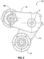
Figure 2 is a top view of the tensioner shown inFigure 1 , having first and second tensioner arms; -
Figure 3 is an exploded perspective view of the tensioner shown inFigure 1 ; -
Figure 4 is a sectional side view of the tensioner shown inFigure 1 ; -
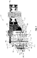
Figure 5 is another sectional side view of the tensioner shown inFigure 1 illustrating forces acting on the first tensioner arm; -
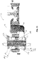
Figure 6 is another sectional side view of the tensioner shown inFigure 1 illustrating forces acting on the second tensioner arm; -
Figure 7 is a sectional side view of the tensioner shown inFigure 1 , with an alternative damping arrangement, according to another embodiment of the present disclosure; -
Figure 8 is a sectional side view of the tensioner shown inFigure 1 , with another alternative damping arrangement, according to another embodiment of the present disclosure; -
Figure 9 is a sectional side view of the tensioner shown inFigure 1 , with yet another alternative damping arrangement, according to another embodiment of the present disclosure; -
Figure 10 is a sectional side view of the tensioner shown inFigure 1 , with yet another alternative damping arrangement, according to another embodiment of the present disclosure; -
Figure 11 is a sectional side view of the tensioner shown inFigure 1 , with yet another alternative damping arrangement, according to another embodiment of the present disclosure; -
Figure 12 is an exploded perspective view of the tensioner shown inFigure 11 ; and -
Figures 13 and 14 are perspective views of two variants of the tensioner as shown in any ofFigures 7-12 . - For simplicity and clarity of illustration, where considered appropriate, reference numerals may be repeated among the Figures to indicate corresponding or analogous elements. In addition, numerous specific details are set forth in order to provide a thorough understanding of the embodiments described herein. However, it will be understood by those of ordinary skill in the art that the embodiments described herein may be practiced without these specific details. In other instances, well-known methods, procedures and components have not been described in detail so as not to obscure the embodiments described herein. Also, the description is not to be considered as limiting the scope of the embodiments described herein.
- Various terms used throughout the present description may be read and understood as follows, unless the context indicates otherwise: "or" as used throughout is inclusive, as though written "and/or"; singular articles and pronouns as used throughout include their plural forms, and vice versa; similarly, gendered pronouns include their counterpart pronouns so that pronouns should not be understood as limiting anything described herein to use, implementation, performance, etc. by a single gender; "exemplary" should be understood as "illustrative" or "exemplifying" and not necessarily as "preferred" over other embodiments. Further definitions for terms may be set out herein; these may apply to prior and subsequent instances of those terms, as will be understood from a reading of the present description.
-
Figure 2 is a top view of an embodiment of atensioner 10 usable for tensioning an endless drive member 11 (Figure 1 ). Theendless drive member 11 may be for use on anengine 13 for a vehicle (not shown) and may be connected to acrankshaft pulley 912, awater pump pulley 960, a motor/generator unit pulley 950 for a motor/generator unit 916 (also referred to as an MGU 916), and anidler 925. The MGU 916 may be used for a number of purposes, including, for example, driving accessories such as the water pump or an air conditioning compressor (not shown) via theendless drive member 11 when theengine 13 is off temporarily, (e.g. when the vehicle is at a stoplight and theengine 13 is turned off to conserve fuel as occurs automatically in some hybrid vehicles). The MGU 916 could be used to provide a BAS drive capability to theengine 13 so that theengine 13 may be started by the MGU 916 through theendless drive member 11. - The
endless drive member 11 may be a belt, or alternatively, it may be any other suitable type of endless drive member. In instances where theendless drive member 11 is a belt, it may be any suitable type of belt, such as a flat belt, a V belt, a poly-V belt, a timing belt. In instances where - Referring to
Figures 3 and4 , thetensioner 10 includes a base 12 that is mountable to astationary structure 99 such as an engine block. The base 12 may be in the form of a hollow shaft that defines a tensioner arm pivot axis A that has a mounting fastener (e.g. a threaded fastener) 13 that passes therethrough and that mounts into a mounting aperture (e.g. a threaded aperture) in thestationary structure 99. Thetensioner 10 further includes a first tensioning arm 14 (which may be referred to as a lower tensioner arm) and a second tensioning arm 16 (which may be referred to as an upper tensioner arm). Thefirst tensioning arm 14 is pivotably mounted to thebase 12. In the example, shown thefirst tensioner arm 14 has a pass-throughaperture 18 for mounting to thebase 12. A first bushing arrangement that, in this example includes first and secondlower bushings first arm aperture 18 and the outer surface of the base 12 to protect against metal-to-metal contact between the base 12 and thefirst arm 14. Thebushings bushings bushings - The
second tensioner arm 16 also includes a pass-throughaperture 24 for pivotably mounting thesecond arm 16 to thebase 12. A second bushing arrangement which may be similar to the first bushing arrangement (and which in this example includes first and secondupper bushings 26 and 28), may be provided in the radial space between theaperture 24 and the outer surface of thebase 12. - A tensioner
arm biasing member 30 is provided and has afirst end 32 that is engaged with adrive face 34 on thefirst tensioner arm 14 and asecond end 36 that is engaged with asecond drive face 38 on thesecond tensioner arm 16 so as to bias the first and second arms in respective first and second free arm directions into thebelt 11. The free arm direction is the direction that thetensioner arm member 30 if there were no belt present to resist the arm's movement. By contrast, the load stop direction is the direction thearm 16 would be moved in in if the belt tension were sufficiently high to overcome the biasing force of the biasingmember 30. In general the free arm direction for a tensioner arm is a direction of movement that bring the tensioner arm into the belt, and the load stop direction is a direction of movement that brings the tensioner arm away from the belt. The tensionerarm biasing member 30 may be any suitable type of biasing member such as, for example, a torsion spring. - Each of the
tensioner arms pulley dust shield 50 that assists in protecting the bearing in the pulley from dust and debris. A mounting fastener (e.g. a threaded fastener) 52 is used to mount thepulley respective tensioner arm - As shown in
Figure 1 , eachpulley respective belt span belt 11. The belt spans 11a and 11b engaged by thepulleys MGU pulley 950. Thetensioner 10 operates on thosespans MGU 916 is being operated as a motive device to drive the belt 11 (in which case the tension inbelt span 11b will be relatively high and the belt tension inbelt span 11a will be relatively low), or whether thebelt 11 is being driven by theengine 13 and theMGU 916 is either off or is acting as a generator. - Referring to
Figure 4 , one or more (in this instance, two)axial preload members 40 are positioned on ashoulder 42 on thebase 12, and are positioned to apply an axial biasing force on thelower tensioner arm 14, which may be referred to as an axial preload. Theaxial preload members 40 may be any suitable type of biasing members such as, for example, Belleville washers, which can generate large biasing forces and which are compact. Theaxial preload members 40 do not directly engage thearm 14; instead, a support member (e.g. a metallic disc) 44 is provided between the biasing members and thearm 14. Furthermore, thebushing 22 has aflange portion 46 that is also present between theaxial preload members 40 and thearm 14, to prevent direct sliding movement between thearm 14 and thesupport member 44. The axial preload may be applied about the circumference of thelower arm 14, at an average radius r, as shown inFigure 5 . The function of theaxial preload members 40 is described further below. - A damping
structure 54 that includes a polymeric (e.g. unfilled (non-reinforced) nylon) tensionerarm damping member 56 and a metallic (e.g. steel)sleeve 58 that holds the dampingmember 56 and protects the dampingmember 56 against damage from engagement with thetorsion spring 30. The dampingmember 56 provides damping for the movement of thetensioner arm 16. The components of the tensioner arm assembly may be similar to the analogous components described inPCT publication no. WO2013/059929 , the contents of which are incorporated herein in their entirety. As thetorsion spring 30 expands, during movement of thetensioner arms member 56 is driven against the inside wall of a cup portion 59 of thelower tensioner arm 14. - A slide disc shown at 60 is provided between a flange portion of the
upper bushing 20 and a flange portion of thelower bushing 28, so as to support the rotation of the twotensioner arms front disc 62 is provided between the head of thefastener 13 and a flange portion of theupper bushing 26. - Referring to
Figure 5 , during operation, the belt 11 (Figure 2 ) applies a hub load shown at F3 to thefirst pulley 46, which results in a force on thefirst arm 14. This hub load F3 introduces a tipping force to thelower arm 14 that, if unaddressed can result in yaw in thelower arm 14. This can, in turn, result in noise and wear problems with thebelt 11, and can furthermore cause uneven wear in thebushings bushings arm 14 and thebase 12 and over time, premature failure of thetensioner 10. To counteract the tipping force caused by the hub load F3, theaxial preload members 40 are selected to apply a sufficiently high axial preload (shown at F4 inFigure 5 ) to thefirst arm 14 that a resulting radially directed counterforce applied to thebushings bushings arm 14, the axial preload F4 is always positioned to counteract the bushing hub load that results from the pulley hub load F3. - In an example, the hub load F3 on the
pulley 46 when thefirst tensioner arm 14 is at a particular position may be 395N. The bushing hub load that results from the pulley hub load F3 is determined as follows: BHL = F3 x L3 / BL, where BHL is the bushing hub load, F3 is the pulley hub load, L3 is the axial distance from the pulley hub load to the bottom of thebushings bushings - The counterforce applied to the
bushings axial preload members 40 is determined as follows: CF = F4 x L4 / (BL / 2), wherein CF is the counterforce, F4 is the axial preload, and L4 is the radius r of the axial preload. In a case where the axial preload members are selected to apply an axial preload F4 = 1000N at a radius r of 14.5mm, the resultant counterforce is 1318N. Because the counterforce exceeds the bushing hub load, no moment is introduced that causes uneven wear to thebushings bushings tensioner 10. It will be noted that, while an example was described with thearm 14 at a particular position, the counterforce generated by theaxial preload members 40 may be sufficiently high so that it is at least approximately as great as the bushing hub load throughout a range of positions of thetensioner arm 14 and preferably throughout substantially all of the positions that thearm 14 will move to during operation within the design conditions of the engine 13 (Figure 1 ). - The mechanics of the
upper tensioner arm 16 will now be described. The pulley hub load is shown at F1 and is in this example, 486N. Thesecond end 34 of thespring 30 applies a force F2 on thetensioner arm 16. Thesecond end 34 of thespring 30 may be oriented so that the force F2 is generally in the same direction as the force F1 (i.e. the forces are additive). These forces are resisted by a reaction force through thebushings Figure 6 , is close to the center of thebushings upper bushings upper arm 16 overall, may be said to be in balance. This arrangement in relation to theupper arm 16 may be as described inPCT publication no WO2010/037232 , the contents of which are incorporated herein by reference in their entirety. Providing a reaction force that is approximately centered axially on the bushings results in more even wear and a resulting longer life for thebushings - As explained above, there is a force F2 that is shown to be exerted by the
second end 36 of thespring 30 on theupper tensioner arm 16 in the diagram shown inFigure 6 . However, as can be seen inFigure 5 , there is no analogous force shown to be exerted by thefirst end 32 of thespring 30 on thelower tensioner arm 14. A reason there is no analogous force shown for thelower tensioner arm 14 is that the forces exerted by thespring 30 on thelower arm 14 essentially cancel out. More specifically, the coils (shown at 61) of the tensionerarm biasing member 30 expand radially proportionately to a tensioning force applied by the first and second ends 32 and 36 to the first andsecond tensioner arms structure 54 is driven to apply a frictional damping force to the first tensioner arm 14 (by engagement with the cup portion 59 of the first tensioner arm 14) that is proportional to an amount of radial expansion of the tensionerarm biasing member 30. As a result of this arrangement the tensioning force exerted by thefirst end 32 of thespring 30 on thelower arm 14 is substantially cancelled by a force exerted through the dampingstructure 54 on the cup portion 59 of thelower arm 14 from expansion of the upper coils 61 of thespring 30. - It will be noted that, while an example was described with the
arm 16 at one particular position, the reaction force generated at the second bushing arrangement may be approximately centered axially along the second bushing arrangement throughout a range of positions of thetensioner arm 16. - Thus by providing both of the features described above in relation to increasing the operating life of the
bushings tensioner 10 may be longer than that of other V tensioners of the prior art. - For greater certainty, it will be noted that the benefits described above for the
bushings bushings - It will be noted that, in
Figures 4 and5 , the lengths of the arrows representing forces F1, F2, F3 and F4 are not to be taken as being indicative of the magnitudes of the forces being represented. - An
installation pin 64 may be provided which is insertable and removable fromapertures second tensioner arms arms belt 11. Once thebelt 11 is installed, the installation pin (or more generally an arm locking member) can be removed, permitting thearms belt 11. - Reference is made to
Figures 7-14 which show thetensioner 10 with several different arrangements of damping structures. Small differences may be present in certain elements of thetensioner 10 in each of these figures, which are explained. InFigures 7-13 , it will be noted that the tensioner does not include the dampingstructure 54 that is present in thetensioner 10 inFigures 1-6 . -
Figure 7 shows a sectional view of thetensioner 10 including a first tensionerarm damping arrangement 100 including a first radial damping portion 102 positioned radially between thefirst tensioner arm 14 and thebase 12, and a first axial dampingportion 104. The first radial damping portion 102 and the first axial dampingportion 104 cooperate to provide damping to movement of thefirst tensioner arm 14. Thetensioner 10 inFigure 7 further includes a second tensionerarm damping arrangement 106 including a second radial damping portion 108 positioned radially between thesecond tensioner arm 16 and thebase 12 and a second axial dampingportion 110. The second radial damping portion 108 and the second axial dampingportion 110 cooperate to provide damping to movement of thesecond tensioner arm 16. Thetensioner 10 inFigure 7 further includes a dampingsystem biasing member 112 that is engaged between the first andsecond tensioner arms portions Figure 7 as being directly along axis A, however this is simply their representation as point forces. It will be noted that the force FB1 is a distributed force that is symmetrically positioned all the way around the axis A and oriented axially, in a proximal direction (i.e. towards the proximal end of the base 12). Thus, the force FB1 and the force FB2 are balanced evenly about the axis A inhibiting any lean on thetensioner arms tensioner 10. For the purposes ofFigures 7-14 , the proximal end of the base 12 (shown at 113) is the end of the base 12 that is engaged with thestationary member 99 when thetensioner 10 is installed. Analogously, thebase 12 has adistal end 114 that is the end that is opposite to the proximal end 113. In the embodiments shown, thefirst tensioner arm 14 is the arm that is proximally positioned and thesecond tensioner arm 16 is the arm that is distally positioned. - In the embodiments shown, the first axial damping
portion 104 includes adistal portion 116 that cooperates with adistal surface 118 on thefirst tensioner arm 14 to dampen movement thereof, and a firstproximal portion 120 that cooperates with aproximal surface 122 on thefirst tensioner arm 14 to dampen movement thereof. Similarly, the second axial dampingportion 110 includes adistal portion 124 that cooperates with adistal surface 126 on thesecond tensioner arm 16 to dampen movement thereof. The second axial dampingportion 110 inFigure 7 further includes aproximal portion 128 that cooperates with a proximal surface 130 on thesecond tensioner arm 16 to dampen movement thereof. - In the embodiment shown in
Figure 7 , the first tensionerarm damping arrangement 100 is provided by a firstdistal tophat member 132 and a firstproximal tophat member 134. Each of the first distal and firstproximal tophat members cylinder 136 and aflange 138. Thecylinder 136 surrounds thebase 12. Examples of suitable tophat members are shown as thebushings Figures 3-6 . Thetophat members first tensioner arm 14. For example, thetophat members - The
tophat members first tensioner arm 14 and may move relative to the base 12 when thearm 14 moves. Thus the frictional damping provided by thetophat members washer support disc 199, discussed further below). In the embodiment shown inFigure 7 , thecylinders 136 from each of thetophat members flanges 138 from the twotophat members portion 110. Theflange 138 of the firstdistal tophat member 132 makes up thedistal portion 116 of the first axial dampingportion 110. Theflange 138 of the firstproximal tophat member 134 makes up theproximal portion 120 of the first axial dampingportion 110. - In the embodiment shown in
Figure 7 , the second tensionerarm damping arrangement 106 is provided by a seconddistal tophat member 140, and also by a distal facing portion of theflange 138 from the firstdistal tophat member 132. The seconddistal tophat member 140 may be similar to thetophat members Figure 7 , it can be seen therefore that thedistal portion 116 of the first axial dampingportion 104 is integral with theproximal portion 128 of the second axial dampingportion 110. In other embodiments, however, such as the embodiment shown inFigure 8 , thedistal portion 116 of the first axial dampingportion 104 is provided on another tophat member shown at 180 and is therefore separate from theproximal portion 128 of the second axial dampingportion 110. Thetophat member 140 includes acylinder 136 that surrounds thebase 12, and aflange 138 which makes up thedistal portion 124 of the second axial dampingportion 110. - In
Figure 8 , as noted above, the second tensionerarm damping arrangement 106 includes a secondproximal tophat member 142 which may be similar to thetophat members cylinder 136 that surrounds thebase 12, and aflange 138. Theflange 138 of thetophat member 142 inFigure 8 makes up theproximal portion 128 of the second axial dampingportion 110. - Reference is made to
Figure 11 . In the embodiment shown inFigure 11 , the first tensionerarm damping arrangement 100 and the second tensionerarm damping arrangement 106 together include a firstarm tophat member 144, a second arm tophat member 146, and a dampingdisc 148. The first and secondarm tophat members 144 and 146 may be similar to thetophat members tophat member 144 and 146 includes acylinder 136 that surrounds thebase 12, and aflange 138. Theflange 138 of the firstarm tophat member 144 cooperates with theproximal surface 122 on thefirst tensioner arm 14 to dampen movement thereof. Theflange 138 of the second arm tophat member 146 cooperates with adistal surface 126 on thesecond tensioner arm 16 to dampen movement thereof. The dampingdisc 148 is positioned to cooperate with thedistal surface 118 on thefirst tensioner arm 14 and a proximal surface 130 on thesecond tensioner arm 16 to dampen movement of either of the first andsecond tensioner arms second tensioner arms - In the embodiment shown in
Figure 11 , thecylinder 136 of each of the first and secondarm tophat members 144 and 146 has a radiallyouter surface 150 that is tapered (i.e. that has a diameter that increases towards the flange 138). Correspondingly, the inner faces of thetensioner arms 14 and 16 (shown at 152 and 154 respectively) are also tapered so as to mate with theouter surface 150 of thecylinder 136. By having taperedinner surfaces 152 and 154 on thetensioner arms tensioner arms -
Figure 12 is an exploded view of thetensioner 10 shown inFigure 11 . - As can be seen, the damping
system biasing member 112 shown inFigures 7-12 includes at least one spring washer 160 (e.g. at least one Belleville washer) that is positioned to move (i.e. to pivot) with one of the first andsecond tensioner arms support disc 199 that is positioned to move with said one of the first andsecond tensioner arms spring washer 160 and whichever of the first and second axial dampingportions second tensioner arms Figures 7-12 , the spring washer(s) 160 and thesupport disc 199 move (i.e. pivot) with thesecond tensioner arm 16 and thesupport disc 199 is positioned between the spring washer(s) 160 and the first axial dampingportion 104 on thefirst tensioner arm 14. This means that there is frictional engagement between thesupport disc 199 and whatever damping surface is adjacent to it (e.g. theflange 138 on the firstdistal tophat 132 as shown inFigure 7 ). - The number of
spring washers 160 used may be selected based on the amount of damping force that will be provided for the particular engine. - The
support disc 199 may be made from a metallic material so as to inihibit gouging by the spring washer(s) 160 applying force on it. - It will be understood that other types of damping system biasing members could alternatively be used.
-
Figure 10 shows thetensioner 10 with a proximal and a distal tophat member on eachtensioner arm system biasing member 112 positioned proximal relative to the first andsecond tensioner arms Figure 9 , on the other hand, shows thetensioner 10 with a proximal and a distal tophat member on eachtensioner arm system biasing member 112 positioned distal relative to the first andsecond tensioner arms member 112 is positioned proximal to thearms arms support disc 199 may be provided between the tophat member that is distal to thefirst arm 14 and the tophat member that is proximal to thesecond arm 16. - It will further be noted that it may be advantageous to provide a tensioner with three tophat members (e.g. similar to the embodiment shown in
Figure 7 ) but without regard to the location of the biasing member 112 (in other words, with the biasingmember 112 distal to the first andsecond arms member 112 proximal to the first andsecond arms 14 and 16). In embodiments in which three tophat members are provided the tophat shown at 132 (Figure 7 ) may be considered to be an intermediate tophat member, wherein theflange 138 of theintermediate tophat member 132 is positioned to cooperate with adistal surface 118 on thefirst tensioner arm 14 and a proximal surface 130 on thesecond tensioner arm 16 to dampen movement of either of the first andsecond tensioner arms second tensioner arms tophat member 134 may be referred in such embodiments as a first arm tophat member and thetophat member 140 may be referred as a second arm tophat member. While theintermediate tophat member 132 is shown as having its cylinder directed proximally so as to engage and support thefirst tensioner arm 14, it is alternatively possible for theintermediate tophat member 132 to be oriented such that itscylinder 136 is directed distally and supports thesecond tensioner arm 16 and with itsflange 138 in direct engagement with the proximal surface 130 of thesecond tensioner arm 16. In such a case, the biasingmember 112 would be positioned proximal to theflange 138 and would move with thefirst tensioner arm 14. - The
arms arm 14 may have itspulley 46 arranged distally on thearm 14, while thearm 16 may have its pulley arranged proximally on thearm 16. By contrast, in the embodiment shown inFigure 13 , thepulleys arms Figure 14 , thepulleys arms - Those skilled in the art will appreciate that a variety of modifications may be made to the embodiments described herein without departing from the fair meaning of the accompanying claims.
-
- 1. A tensioner for an endless drive member, comprising:
- a base having a proximal end and a distal end and is mountable at the proximal end to a stationary structure;
- a first tensioner arm that is pivotable relative to the base about a common axis;
- a first tensioner pulley that is mounted for rotation on the first tensioner arm about a first pulley axis that is spaced from the common axis;
- a second tensioner arm that is pivotable relative to the base about the common axis;
- a second tensioner pulley that is mounted for rotation on the second tensioner arm about a second pulley axis that is spaced from the common axis and spaced from the first pulley axis;
- a tensioner biasing member that is engaged between the first and second tensioner arms to urge the first and second tensioner pulleys towards each other;
- a first tensioner arm damping arrangement including a first radial damping portion positioned radially between the first tensioner arm and the base, and a first axial damping portion, wherein the first radial damping portion and the first axial damping portion cooperate to provide damping to movement of the first tensioner arm;
- a second tensioner arm damping arrangement including a second radial damping portion positioned radially between the second tensioner arm and the base and a second axial damping portion, wherein the second radial damping portion and the second axial damping portion cooperate to provide damping to movement of the second tensioner arm;
- a damping system biasing member that is engaged between the first and second tensioner arms and that exerts first and second damping system biasing forces on the first and second axial damping portions respectively, wherein the first and second damping system biasing forces are directed in axially opposite directions from one another.
- 2. A tensioner as claimed in embodiment 1, wherein the first axial damping portion includes a distal portion that cooperates with a distal surface on the first tensioner arm to dampen movement thereof, and a first proximal portion that cooperates with a proximal surface on the first tensioner arm to dampen movement thereof.
- 3. A tensioner as claimed in embodiment 2, wherein the second axial damping portion includes a distal portion that cooperates with a distal surface on the second tensioner arm to dampen movement thereof.
- 4. A tensioner as claimed in embodiment 3, wherein the second axial damping portion further includes a proximal portion that cooperates with a proximal surface on the second tensioner arm to dampen movement thereof.
- 5. A tensioner as claimed in embodiment 4, wherein the distal portion of the first axial damping portion is integral with the proximal portion of the second axial damping portion.
- 6. A tensioner as claimed in embodiment 4, wherein the distal portion of the first axial damping portion is separate from the proximal portion of the second axial damping portion.
- 7. A tensioner as claimed in embodiment 2, wherein the first tensioner arm damping arrangement includes a first distal tophat member and a first proximal tophat member, wherein each of the first distal and first proximal tophat members includes a cylinder that surrounds the base, and a flange, wherein the flange of the first distal tophat member makes up the distal portion of the first axial damping portion, and wherein the flange of the first proximal tophat member makes up the proximal portion of the first axial damping portion.
- 8. A tensioner as claimed in embodiment 7, wherein the second axial damping portion includes a distal portion that cooperates with a distal surface on the second tensioner arm to dampen movement thereof, and
wherein the second tensioner arm damping arrangement includes a second distal tophat member, wherein the second distal tophat member includes a cylinder that surrounds the base, and a flange, wherein the flange of the second distal tophat member makes up the distal portion of the second axial damping portion. - 9. A tensioner as claimed in embodiment 8, wherein the second axial damping portion further includes a proximal portion that cooperates with a proximal surface on the second tensioner arm to dampen movement thereof, and
wherein the second tensioner arm damping arrangement includes a second proximal tophat member, wherein the second proximal tophat member includes a cylinder that surrounds the base, and a flange, wherein the flange of the second proximal tophat member makes up the proximal portion of the second axial damping portion. - 10. A tensioner as claimed in embodiment 1, wherein the first tensioner arm damping arrangement and the second tensioner arm damping arrangement together include a first arm tophat member, a second arm tophat member, and a damping disc, wherein the first and second arm tophat members each include a cylinder that surrounds the base, and a flange,
- wherein the flange of the first arm tophat member cooperates with a proximal surface on the first tensioner arm to dampen movement thereof, and wherein the flange of the second arm tophat member cooperates with a distal surface on the second tensioner arm to dampen movement thereof.
- wherein the damping disc is positioned to cooperate with a distal surface on the first tensioner arm and a proximal surface on the second tensioner arm to dampen movement of either of the first and second tensioner arms relative to the other of the first and second tensioner arms.
- 11. A tensioner as claimed in
embodiment 10, wherein the cylinder on each of the first and second arm tophat members has a radially outer surface that is tapered. - 12. A tensioner as claimed in embodiment 1, wherein the damping system biasing member includes at least one spring washer that is positioned to move with one of the first and second tensioner arms, and least one support disc that is positioned to move with said one of the first and second tensioner arms, and that is positioned between the at least one spring washer and whichever of the first and second axial damping portions is associated with the other of the first and second tensioner arms.
- 13. A tensioner for an endless drive member, comprising:
- a base having a proximal end and a distal end and is mountable at the proximal end to a stationary structure;
- a first tensioner arm that is pivotable relative to the base about a common axis;
- a first tensioner pulley that is mounted for rotation on the first tensioner arm about a first pulley axis that is spaced from the common axis;
- a second tensioner arm that is pivotable relative to the base about the common axis;
- a second tensioner pulley that is mounted for rotation on the second tensioner arm about a second pulley axis that is spaced from the common axis and spaced from the first pulley axis;
- a tensioner biasing member that is engaged between the first and second tensioner arms to urge the first and second tensioner pulleys towards each other;
- a first tensioner arm damping arrangement including a first radial damping portion positioned radially between the first tensioner arm and the base, and a first axial damping portion, wherein the first radial damping portion and the first axial damping portion cooperate to provide damping to movement of the first tensioner arm;
- a second tensioner arm damping arrangement including a second radial damping portion positioned radially between the second tensioner arm and the base and a second axial damping portion, wherein the second radial damping portion and the second axial damping portion cooperate to provide damping to movement of the second tensioner arm; and
- a damping system biasing member that is positioned to apply an axial biasing force to the first and second axial damping portions to generate friction thereat;
- wherein the first tensioner arm damping arrangement and the second tensioner arm damping arrangement together include a first arm tophat member, a second arm tophat member, and an intermediate tophat member, wherein the first arm tophat member, the second arm tophat member and the intermediate tophat member each include a cylinder that surrounds the base, and a flange,
- wherein the flange of the first arm tophat member cooperates with a proximal surface on the first tensioner arm to dampen movement thereof, and wherein the flange of the second arm tophat member cooperates with a distal surface on the second tensioner arm to dampen movement thereof,
- wherein the flange of the intermediate tophat member is positioned to cooperate with a distal surface on the first tensioner arm and a proximal surface on the second tensioner arm to dampen movement of either of the first and second tensioner arms relative to the other of the first and second tensioner arms.
Claims (15)
- A tensioner for an endless drive member, comprising:a base having a proximal end and a distal end and is mountable at the proximal end to a stationary structure;a first tensioner arm that is pivotable relative to the base about a common axis;a first tensioner pulley that is mounted for rotation on the first tensioner arm about a first pulley axis that is spaced from the common axis;a second tensioner arm that is pivotable relative to the base about the common axis;a second tensioner pulley that is mounted for rotation on the second tensioner arm about a second pulley axis that is spaced from the common axis and spaced from the first pulley axis;a tensioner biasing member that is engaged between the first and second tensioner arms to urge the first and second tensioner pulleys towards each other;a first tensioner arm damping arrangement including a first radial damping portion positioned radially between the first tensioner arm and the base, and a first axial damping portion, wherein the first radial damping portion and the first axial damping portion cooperate to provide damping to movement of the first tensioner arm;a second tensioner arm damping arrangement including a second radial damping portion positioned radially between the second tensioner arm and the base and a second axial damping portion, wherein the second radial damping portion and the second axial damping portion cooperate to provide damping to movement of the second tensioner arm;a damping system biasing member that is positioned to apply an axial biasing force to the first and second axial damping portions to generate friction thereat.
- A tensioner as claimed in claim 1, wherein the first tensioner arm damping arrangement and the second tensioner arm damping arrangement together include a first arm tophat member, a second arm tophat member, and an intermediate tophat member, wherein the first arm tophat member, the second arm tophat member and the intermediate tophat member each include a cylinder that surrounds the base, and a flange,wherein the flange of the first arm tophat member cooperates with a proximal surface on the first tensioner arm to dampen movement thereof, and wherein the flange of the second arm tophat member cooperates with a distal surface on the second tensioner arm to dampen movement thereof,wherein the flange of the intermediate tophat member is positioned to cooperate with a distal surface on the first tensioner arm and a proximal surface on the second tensioner arm to dampen movement of either of the first and second tensioner arms relative to the other of the first and second tensioner arms.
- A tensioner as claimed in claim 1 or 2, wherein the damping system biasing member comprises at least one spring washer and least one support disc.
- A tensioner as claimed in claim 3, wherein the at least one spring washer is positioned to move with one of the first and second tensioner arms, and the least one support disc is positioned to move with said one of the first and second tensioner arms, and which is positioned between the at least one spring washer and whichever of the first and second axial damping portions associated with the other of the first and second tensioner arms.
- A tensioner as claimed in any of claims 1 to 4, wherein the damping system biasing member is provides in one of the following positions i) to iii):i) the damping system biasing member is engaged between the first and second tensioner arms and that exerts first and second damping system biasing forces on the first and second axial damping portions respectively,ii) the damping system biasing member is positioned proximal relative to the first and second tensioner arms,iii) the damping system biasing member is positioned distal relative to the first and second tensioner arms.
- A tensioner as claimed in claim 1, wherein the first axial damping portion includes a distal portion that cooperates with a distal surface on the first tensioner arm to dampen movement thereof, and a first proximal portion that cooperates with a proximal surface on the first tensioner arm to dampen movement thereof.
- A tensioner as claimed in claim 6, wherein the second axial damping portion includes a distal portion that cooperates with a distal surface on the second tensioner arm to dampen movement thereof.
- A tensioner as claimed in claim 7, wherein the second axial damping portion further includes a proximal portion that cooperates with a proximal surface on the second tensioner arm to dampen movement thereof.
- A tensioner as claimed in claim 8, wherein the distal portion of the first axial damping portion is integral with the proximal portion of the second axial damping portion.
- A tensioner as claimed in claim 8, wherein the distal portion of the first axial damping portion is separate from the proximal portion of the second axial damping portion.
- A tensioner as claimed in claim 6, wherein the first tensioner arm damping arrangement includes a first distal tophat member and a first proximal tophat member, wherein each of the first distal and first proximal tophat members includes a cylinder that surrounds the base, and a flange, wherein the flange of the first distal tophat member makes up the distal portion of the first axial damping portion, and wherein the flange of the first proximal tophat member makes up the proximal portion of the first axial damping portion.
- A tensioner as claimed in claim 11, wherein the second axial damping portion includes a distal portion that cooperates with a distal surface on the second tensioner arm to dampen movement thereof, and
wherein the second tensioner arm damping arrangement includes a second distal tophat member, wherein the second distal tophat member includes a cylinder that surrounds the base, and a flange, wherein the flange of the second distal tophat member makes up the distal portion of the second axial damping portion. - A tensioner as claimed in claim 12, wherein the second axial damping portion further includes a proximal portion that cooperates with a proximal surface on the second tensioner arm to dampen movement thereof, and
wherein the second tensioner arm damping arrangement includes a second proximal tophat member, wherein the second proximal tophat member includes a cylinder that surrounds the base, and a flange, wherein the flange of the second proximal tophat member makes up the proximal portion of the second axial damping portion. - A tensioner as claimed in claim 1, wherein the first tensioner arm damping arrangement and the second tensioner arm damping arrangement together include a first arm tophat member, a second arm tophat member, and a damping disc, wherein the first and second arm tophat members each include a cylinder that surrounds the base, and a flange,wherein the flange of the first arm tophat member cooperates with a proximal surface on the first tensioner arm to dampen movement thereof, and wherein the flange of the second arm tophat member cooperates with a distal surface on the second tensioner arm to dampen movement thereof.wherein the damping disc is positioned to cooperate with a distal surface on the first tensioner arm and a proximal surface on the second tensioner arm to dampen movement of either of the first and second tensioner arms relative to the other of the first and second tensioner arms.
- A tensioner as claimed in claim 14, wherein the cylinder on each of the first and second arm tophat members has a radially outer surface that is tapered.
Applications Claiming Priority (3)
| Application Number | Priority Date | Filing Date | Title |
|---|---|---|---|
| US201662394081P | 2016-09-13 | 2016-09-13 | |
| PCT/CA2017/051078 WO2018049521A1 (en) | 2016-09-13 | 2017-09-13 | V tensioner and endless drive arrangement |
| EP17849962.0A EP3513097B1 (en) | 2016-09-13 | 2017-09-13 | V tensioner and endless drive arrangement |
Related Parent Applications (2)
| Application Number | Title | Priority Date | Filing Date |
|---|---|---|---|
| EP17849962.0A Division EP3513097B1 (en) | 2016-09-13 | 2017-09-13 | V tensioner and endless drive arrangement |
| EP17849962.0A Division-Into EP3513097B1 (en) | 2016-09-13 | 2017-09-13 | V tensioner and endless drive arrangement |
Publications (1)
| Publication Number | Publication Date |
|---|---|
| EP4006380A1 true EP4006380A1 (en) | 2022-06-01 |
Family
ID=61618564
Family Applications (2)
| Application Number | Title | Priority Date | Filing Date |
|---|---|---|---|
| EP22151788.1A Pending EP4006380A1 (en) | 2016-09-13 | 2017-09-13 | V tensioner and endless drive arrangement |
| EP17849962.0A Active EP3513097B1 (en) | 2016-09-13 | 2017-09-13 | V tensioner and endless drive arrangement |
Family Applications After (1)
| Application Number | Title | Priority Date | Filing Date |
|---|---|---|---|
| EP17849962.0A Active EP3513097B1 (en) | 2016-09-13 | 2017-09-13 | V tensioner and endless drive arrangement |
Country Status (5)
| Country | Link |
|---|---|
| US (1) | US11174921B2 (en) |
| EP (2) | EP4006380A1 (en) |
| JP (1) | JP7003119B6 (en) |
| CN (1) | CN109690134B (en) |
| WO (1) | WO2018049521A1 (en) |
Families Citing this family (3)
| Publication number | Priority date | Publication date | Assignee | Title |
|---|---|---|---|---|
| DE102017217645A1 (en) * | 2017-10-05 | 2019-04-11 | Bayerische Motoren Werke Aktiengesellschaft | Belt tensioner |
| DE102020004335A1 (en) * | 2020-07-20 | 2022-01-20 | Muhr Und Bender Kg | Belt tensioning device and belt drive with such a belt tensioning device |
| WO2022034820A1 (en) * | 2020-08-11 | 2022-02-17 | 三菱自動車工業株式会社 | Belt transmission device |
Citations (9)
| Publication number | Priority date | Publication date | Assignee | Title |
|---|---|---|---|---|
| DE4243451A1 (en) | 1992-12-22 | 1994-06-23 | Schaeffler Waelzlager Kg | Tensioner for belt or chain in combustion IC-engine |
| JPH0777251A (en) * | 1993-09-09 | 1995-03-20 | Koyo Seiko Co Ltd | Auto tensioner |
| EP1122464A1 (en) | 2000-01-12 | 2001-08-08 | Litens Automotive GmbH | Tensioner for a flexible drive element |
| DE10253450A1 (en) | 2002-11-16 | 2004-05-27 | Bayerische Motoren Werke Ag | Clamping device for an envelope drive of a unit |
| US20040171448A1 (en) | 2003-01-10 | 2004-09-02 | Muhr Und Bender Kg | Belt tensioning device |
| EP1464871A1 (en) | 2003-04-02 | 2004-10-06 | DAYCO EUROPE S.r.l. | Two-arm belt tensioner |
| WO2010037232A1 (en) | 2008-10-02 | 2010-04-08 | Litens Automotive Partnership | Compact tensioner with sustainable damping |
| WO2013059929A1 (en) | 2011-10-26 | 2013-05-02 | Litens Automotive Partnership | Tensioner with damping structure made from two components with no rotational play therebetween |
| WO2014085917A1 (en) * | 2012-12-07 | 2014-06-12 | Litens Automotive Partnership | Tensioner and endless drive arrangement |
Family Cites Families (112)
| Publication number | Priority date | Publication date | Assignee | Title |
|---|---|---|---|---|
| US613960A (en) * | 1898-11-08 | Belt-tightener | ||
| US1707119A (en) | 1927-04-20 | 1929-03-26 | Frick Co | Belt tightener for sawmill feed mechanism |
| US1971551A (en) * | 1931-04-20 | 1934-08-28 | Charles B Curtiss | Adjustable tightening idler |
| GB1060052A (en) | 1962-06-26 | 1967-02-22 | Massey Ferguson Ltd | Threshing and separating assembly |
| US3811332A (en) * | 1972-08-22 | 1974-05-21 | Fmc Corp | Automatic tensioning device |
| US4473362A (en) * | 1981-07-08 | 1984-09-25 | Litens Automotive Inc. | Belt tensioner with variably proportional damping |
| US4504254A (en) * | 1982-07-28 | 1985-03-12 | Dayco Corporation | Belt tensioner and method of making the same |
| US4698049A (en) * | 1986-04-11 | 1987-10-06 | Litens Automotive Inc. | Belt tensioner with frustoconical pivot bearing |
| US4758208A (en) * | 1987-07-13 | 1988-07-19 | General Motors Corporation | Automatic belt tensioner for vehicle combined starter-generator |
| JPH01143454U (en) | 1988-03-28 | 1989-10-02 | ||
| US4902267A (en) * | 1989-06-12 | 1990-02-20 | Dayco Products, Inc. | Belt tensioner, kit therefor and methods of making the same |
| DE4025936A1 (en) | 1989-08-22 | 1991-03-28 | Gerhard Drews | Removable rigid car roof sliding into-and stowed in car boot - has rear window pivoting upwards under stowed roof, about points each side of lower roof frame |
| DE4040579A1 (en) | 1990-12-19 | 1992-06-25 | Bosch Gmbh Robert | Sensor with housing with inclined lateral mounting surfaces - is mounted in vehicle in required position without cost and complexity of linkage |
| DE19524403C2 (en) | 1995-07-04 | 2000-09-28 | Litens Automotive Gmbh | Bearing for a belt tension arm |
| IT1277619B1 (en) | 1995-08-04 | 1997-11-11 | Castelgarden Spa | BIDIRECTIONAL ELASTIC CHAIN TENSIONER |
| JPH09144821A (en) | 1995-11-20 | 1997-06-03 | Ricoh Co Ltd | Driving transmission device |
| CA2308567C (en) * | 1997-11-26 | 2007-01-09 | Litens Automotive Partnership | Rotary belt tensioner with hydraulic damping |
| JP3129268B2 (en) | 1997-12-26 | 2001-01-29 | 株式会社デンソー | Belt transmission system for internal combustion engine |
| JP3195287B2 (en) | 1997-12-26 | 2001-08-06 | 株式会社デンソー | Belt transmission system for internal combustion engine |
| DE19849469A1 (en) | 1998-10-21 | 2000-05-04 | Mannesmann Ag | Tape storage |
| DE19849659A1 (en) | 1998-10-29 | 2000-05-04 | Schaeffler Waelzlager Ohg | Tensioning device for a traction device |
| DE19849886A1 (en) | 1998-10-29 | 2000-05-11 | Bosch Gmbh Robert | Belt drive, especially in internal combustion engines for driving auxiliary units of a vehicle |
| DE19926647A1 (en) | 1999-06-11 | 2000-12-14 | Schaeffler Waelzlager Ohg | Belt tightener has two tensioning arms and rollers, on joint pivot axle, two bearing eyelets, pin and base element |
| DE19926612A1 (en) * | 1999-06-11 | 2000-12-14 | Schaeffler Waelzlager Ohg | Belt drive of an internal combustion engine |
| DE19926615A1 (en) * | 1999-06-11 | 2000-12-14 | Schaeffler Waelzlager Ohg | Tensioning device for traction devices such as belts or chains |
| DE19926613A1 (en) | 1999-06-11 | 2000-12-14 | Schaeffler Waelzlager Ohg | Belt tightener has two tensioning arms on pivot axle, two tensioning rollers, tensioning spring, thrust pieces, protuberance and recess, and base plate |
| JP3652177B2 (en) | 1999-08-20 | 2005-05-25 | 株式会社デンソー | Belt transmission system for internal combustion engines |
| JP2001107827A (en) | 1999-10-07 | 2001-04-17 | Toyota Motor Corp | Starting device and starting method for internal combustion engine |
| DE20023355U1 (en) | 2000-01-12 | 2003-11-06 | Litens Automotive Gmbh | Automotive motor and drive assembly, includes tension device positioned within belt drive system having combination starter/ generator which drives belt on start-up |
| WO2002010615A1 (en) | 2000-07-27 | 2002-02-07 | Ina-Schaeffler Kg | Tensioning system for a belt-driven starter-generator |
| DE10045143A1 (en) | 2000-07-27 | 2002-02-07 | Schaeffler Waelzlager Ohg | Tensioning system for a belt-driven starter generator |
| JP4133320B2 (en) | 2000-10-03 | 2008-08-13 | ザ ゲイツ コーポレイション | Accessories and motor / generator belt drive tensioners |
| DE10120448A1 (en) | 2001-04-26 | 2002-10-31 | Ina Schaeffler Kg | Device for smoothing of irregular drive moment of especially camshaft of internal combustion engine has facility whereby force of cam follower system is variable dependent upon RPM |
| HU229711B1 (en) * | 2001-07-31 | 2014-05-28 | Litens Automotive Inc | Belt tensioner with installation pin |
| US6857979B2 (en) * | 2001-10-26 | 2005-02-22 | Litens Automotive Partnership | Combination belt tensioner and idler |
| US7163478B2 (en) * | 2001-12-12 | 2007-01-16 | Dayco Products, Llc | Belt tensioner having an automatically adjustable travel stop |
| US6689001B2 (en) * | 2001-12-12 | 2004-02-10 | Dayco Products, Llc | Adaptive belt tensioner system for control of reversible torque load pulley |
| US6736743B2 (en) * | 2002-01-22 | 2004-05-18 | The Gates Corporation | Belt installation tool |
| US6652401B2 (en) * | 2002-02-11 | 2003-11-25 | The Gates Corporation | Method of tuning a belt drive system |
| US6830524B2 (en) * | 2002-05-23 | 2004-12-14 | General Motors Corporation | Crank drive belt system with triple pulley tensioner |
| JP4315362B2 (en) | 2002-08-08 | 2009-08-19 | バンドー化学株式会社 | Belt drive |
| JP4248204B2 (en) | 2002-08-26 | 2009-04-02 | バンドー化学株式会社 | Belt drive |
| US6960145B2 (en) * | 2002-08-30 | 2005-11-01 | Trw, Inc. | Belt tensioner for electric power steering unit |
| DE10253241A1 (en) | 2002-11-15 | 2004-05-27 | Ina-Schaeffler Kg | Clamping device for a traction mechanism drive |
| ITTO20021133A1 (en) * | 2002-12-30 | 2004-06-30 | Dayco Europe Srl | TWO-ARM TENSIONER FOR A BELT DRIVE. |
| DE10321801A1 (en) | 2003-01-10 | 2004-07-29 | Muhr Und Bender Kg | Belt tensioner |
| ITTO20030601A1 (en) | 2003-08-01 | 2005-02-02 | Dayco Europe Srl | TENSIONER FOR A TRANSMISSION BELT OF A MOTOR VEHICLE. |
| ITTO20030819A1 (en) * | 2003-10-17 | 2005-04-18 | Dayco Europe Srl | BI-ARM TENSIONER FOR A TRANSMISSION BELT OF A MOTOR VEHICLE. |
| US7273432B2 (en) * | 2004-01-06 | 2007-09-25 | Litens Automotive Gmbh | Belt tensioner |
| US20050181901A1 (en) * | 2004-02-13 | 2005-08-18 | Chang-Hyun Shin | Double action belt tensioner |
| DE102004015954A1 (en) | 2004-04-01 | 2005-11-10 | Ina-Schaeffler Kg | belt drive |
| DE102004015952A1 (en) | 2004-04-01 | 2005-10-20 | Ina Schaeffler Kg | Clamping system for a traction drive |
| DE102004018390A1 (en) | 2004-04-16 | 2005-12-22 | Ina-Schaeffler Kg | Device for an internal combustion engine |
| DE102004018776A1 (en) | 2004-04-19 | 2005-11-03 | Ina-Schaeffler Kg | Traction drive, in particular belt drive |
| DE102004025216A1 (en) | 2004-05-22 | 2005-12-22 | Ina-Schaeffler Kg | Belt drive for an internal combustion engine |
| DE102004025542A1 (en) | 2004-05-25 | 2005-12-22 | Ina-Schaeffler Kg | friction wheel drive |
| DE102004025936A1 (en) | 2004-05-27 | 2005-12-22 | Ina-Schaeffler Kg | Belt drive for an internal combustion engine |
| EP1756449B1 (en) | 2004-06-03 | 2010-12-08 | Schaeffler Technologies AG & Co. KG | Traction mechanism for an internal combustion engine |
| BRPI0511790A (en) | 2004-06-03 | 2008-01-15 | Schaeffler Kg | cost optimized traction mechanism |
| DE102004028222A1 (en) | 2004-06-09 | 2005-12-29 | Ina-Schaeffler Kg | Belt drive with non-circular gears |
| DE102004028484A1 (en) | 2004-06-11 | 2005-12-29 | Ina-Schaeffler Kg | friction wheel drive |
| WO2006005411A1 (en) | 2004-06-18 | 2006-01-19 | Schaeffler Kg | Wraparound drive unit |
| DE102004030287A1 (en) | 2004-06-23 | 2006-01-12 | Ina-Schaeffler Kg | Belt drive for internal combustion engine with drive calming |
| WO2006002709A1 (en) | 2004-06-30 | 2006-01-12 | Schaeffler Kg | Wraparound drive of internal combustion engines for auxillary assemblies which are coupled with a force-transmitting connection |
| DE102004033974A1 (en) | 2004-07-14 | 2006-02-16 | Ina-Schaeffler Kg | pulley |
| DE102004033927A1 (en) | 2004-07-14 | 2006-02-16 | Ina-Schaeffler Kg | Balance shaft drive |
| DE102004037262A1 (en) | 2004-07-31 | 2006-02-16 | Ina-Schaeffler Kg | traction drive |
| US20060035738A1 (en) | 2004-08-12 | 2006-02-16 | Ina-Schaeffler Kg | Belt drive |
| DE102004039070A1 (en) | 2004-08-12 | 2006-02-23 | Ina-Schaeffler Kg | belt drive |
| DE102004040579A1 (en) | 2004-08-21 | 2006-02-23 | Ina-Schaeffler Kg | Traction drive, in particular for an internal combustion engine |
| DE102004045751A1 (en) | 2004-09-21 | 2006-04-27 | Ina-Schaeffler Kg | Method for designing a control gear having at least one non-circular disk |
| DE102004048280A1 (en) | 2004-10-05 | 2006-04-27 | Ina-Schaeffler Kg | Belt drive for internal combustion engines with drive calming |
| DE102004048283A1 (en) | 2004-10-05 | 2006-04-20 | Ina-Schaeffler Kg | Traction drive with vibration damping |
| KR20070097020A (en) | 2004-10-06 | 2007-10-02 | 쉐플러 카게 | Out-of-round rotation disc for a timing drive |
| DE102004048629A1 (en) | 2004-10-06 | 2006-04-13 | Ina-Schaeffler Kg | Non-circular rotary disk for a timing drive |
| WO2006061180A2 (en) | 2004-12-07 | 2006-06-15 | Schaeffler Kg | Power transmission belt drive for an auxiliary unit of an internal combustion engine |
| DE102004058772A1 (en) | 2004-12-07 | 2006-07-13 | Schaeffler Kg | Power transmission belt drive for auxiliary unit of internal combustion engine, has auxiliary unit which is starter along with crankshaft which is detachably connected to power transmission pulley of crankshaft by means of coupling element |
| DE102004060015A1 (en) | 2004-12-14 | 2006-07-13 | Schaeffler Kg | Power transmission belt drive for auxiliary unit of internal combustion engine, has auxiliary unit which is starter along with crankshaft which is detachably connected to power transmission pulley of crankshaft by means of coupling element |
| JP2006200639A (en) * | 2005-01-21 | 2006-08-03 | Jtekt Corp | Autotensioner |
| US8562466B2 (en) | 2005-03-21 | 2013-10-22 | Litens Automotive Partnership | Belt tensioner with wear compensation |
| US7494434B2 (en) * | 2005-06-15 | 2009-02-24 | Gm Global Technology Operations, Inc. | Belt alternator starter accessory drive with dual tensioner |
| US8075433B2 (en) * | 2005-06-28 | 2011-12-13 | Dayco Products, Llc | Belt tensioner with damping member |
| US20070010362A1 (en) | 2005-07-08 | 2007-01-11 | Schaeffler Kg | Wraparound drive |
| US20070006836A1 (en) | 2005-07-08 | 2007-01-11 | Schaeffler Kg | Traction mechanism drive having vibration damping |
| US20070163529A1 (en) | 2005-07-08 | 2007-07-19 | Schaeffler Kg | Wraparound drive for internal combustion engines having drive damping |
| US20070161444A1 (en) * | 2005-07-08 | 2007-07-12 | Schaeffler Kg | Traction mechanism drive, in particular for an internal combustion engine |
| DE602005018842D1 (en) * | 2005-07-14 | 2010-02-25 | Dayco Europe Srl | CLAMPING DEVICE FOR A DRIVE BELT OF A MOTOR VEHICLE |
| US8002657B2 (en) | 2005-09-01 | 2011-08-23 | Litens Automotive Partnership | Low profile tensioner with arcuate spring |
| DE202005016992U1 (en) * | 2005-10-31 | 2005-12-29 | Litens Automotive Gmbh | Belt tightener for a belt drive in an internal combustion engine comprises a glide element arrangement incorporating at least two opposing gliding surfaces are made of the same material |
| DE102005055927A1 (en) | 2005-11-22 | 2007-10-25 | Luk Lamellen Und Kupplungsbau Beteiligungs Kg | traction drive |
| EP1955320A2 (en) | 2005-12-02 | 2008-08-13 | QUALCOMM Incorporated | Systems, methods, and apparatus for frequency-domain waveform alignment |
| DE102006003461A1 (en) | 2006-01-25 | 2007-09-27 | Schaeffler Kg | traction drive |
| DE102006004533A1 (en) | 2006-02-01 | 2007-08-16 | Schaeffler Kg | Chain drive and use of a chain in a chain drive |
| CN101421540B (en) * | 2006-03-22 | 2012-09-05 | 利滕斯汽车合伙公司 | Tensioner for flexible drives |
| DE102006014942A1 (en) | 2006-03-31 | 2007-10-04 | Schaeffler Kg | Clamping device for use in traction mechanism drive, has coil spring, where tilting moment of spring force of spring and resultant reaction force of drive mutually suspend rotary axis of swivel bearing around imaginary slide tilting axis |
| DE102006017287B4 (en) | 2006-04-12 | 2021-03-25 | Litens Automotive Gmbh | Tensioner for an endless drive |
| US8038555B2 (en) * | 2006-08-31 | 2011-10-18 | Dayco Products, Llc | One-way clutched damper for automatic belt tensioner |
| DE102007042501A1 (en) | 2007-09-07 | 2009-03-26 | Muhr Und Bender Kg | Belt clamping arrangement for belt drive of internal combustion engine of motor vehicle, has clamping rollers clamping respective belts, where one of rollers is translatively movable related to another roller and/or to stationary component |
| DE102008014325A1 (en) | 2008-03-14 | 2009-09-17 | Schaeffler Kg | Belt tensioner for motor vehicle, has torsion spring formed as coil spring whose end center spaced to swivel bearing plane so that tilting torques of tangential spring force and resulting reaction force cancel each other around tilting axis |
| US8142315B2 (en) * | 2008-04-30 | 2012-03-27 | Litens Automotive Partnership | Tensioner with hub load balancing feature |
| DE102008025552B4 (en) | 2008-05-28 | 2020-06-10 | Muhr Und Bender Kg | Belt tensioner for starter-generator application |
| US8092328B2 (en) * | 2009-06-30 | 2012-01-10 | The Gates Corporation | Dual tensioner assembly |
| US8057334B2 (en) * | 2009-09-23 | 2011-11-15 | GM Global Technology Operations LLC | Accessory drive tensioner assembly |
| DE102010019613B4 (en) | 2010-05-06 | 2019-02-21 | Litens Automotive Gmbh | Spanner and endless drive assembly |
| DE102011082764A1 (en) | 2010-10-13 | 2012-04-19 | Schaeffler Technologies Gmbh & Co. Kg | Clamping device for a traction mechanism drive of an internal combustion engine |
| US20130260932A1 (en) * | 2012-03-29 | 2013-10-03 | Joern Adam | Tensioner and endless drive arrangement |
| EP2831468B1 (en) * | 2012-03-29 | 2021-12-01 | Litens Automotive Partnership | Tensioner and endless drive arrangement |
| US9790817B2 (en) * | 2012-10-22 | 2017-10-17 | Litens Automotive Partnership | Tensioner with increased damping |
| EP2937598B1 (en) * | 2014-04-24 | 2020-05-13 | Litens Automotive Partnership | Tensioner with increased damping |
| CN107076278B (en) * | 2014-10-21 | 2020-05-19 | 利滕斯汽车合伙公司 | Endless drive and improved two-arm tensioning system for an endless drive |
| US9651122B2 (en) | 2015-02-05 | 2017-05-16 | Gates Corporation | Dual arm tensioner |
| KR101664672B1 (en) * | 2015-03-20 | 2016-10-10 | 현대자동차주식회사 | Belt auto-tensioner for engine |
-
2017
- 2017-09-13 EP EP22151788.1A patent/EP4006380A1/en active Pending
- 2017-09-13 WO PCT/CA2017/051078 patent/WO2018049521A1/en unknown
- 2017-09-13 JP JP2019513909A patent/JP7003119B6/en active Active
- 2017-09-13 US US16/333,199 patent/US11174921B2/en active Active
- 2017-09-13 EP EP17849962.0A patent/EP3513097B1/en active Active
- 2017-09-13 CN CN201780055760.4A patent/CN109690134B/en active Active
Patent Citations (9)
| Publication number | Priority date | Publication date | Assignee | Title |
|---|---|---|---|---|
| DE4243451A1 (en) | 1992-12-22 | 1994-06-23 | Schaeffler Waelzlager Kg | Tensioner for belt or chain in combustion IC-engine |
| JPH0777251A (en) * | 1993-09-09 | 1995-03-20 | Koyo Seiko Co Ltd | Auto tensioner |
| EP1122464A1 (en) | 2000-01-12 | 2001-08-08 | Litens Automotive GmbH | Tensioner for a flexible drive element |
| DE10253450A1 (en) | 2002-11-16 | 2004-05-27 | Bayerische Motoren Werke Ag | Clamping device for an envelope drive of a unit |
| US20040171448A1 (en) | 2003-01-10 | 2004-09-02 | Muhr Und Bender Kg | Belt tensioning device |
| EP1464871A1 (en) | 2003-04-02 | 2004-10-06 | DAYCO EUROPE S.r.l. | Two-arm belt tensioner |
| WO2010037232A1 (en) | 2008-10-02 | 2010-04-08 | Litens Automotive Partnership | Compact tensioner with sustainable damping |
| WO2013059929A1 (en) | 2011-10-26 | 2013-05-02 | Litens Automotive Partnership | Tensioner with damping structure made from two components with no rotational play therebetween |
| WO2014085917A1 (en) * | 2012-12-07 | 2014-06-12 | Litens Automotive Partnership | Tensioner and endless drive arrangement |
Also Published As
| Publication number | Publication date |
|---|---|
| CN109690134B (en) | 2022-02-18 |
| CN109690134A (en) | 2019-04-26 |
| EP3513097A4 (en) | 2020-05-13 |
| US11174921B2 (en) | 2021-11-16 |
| JP2019529823A (en) | 2019-10-17 |
| WO2018049521A1 (en) | 2018-03-22 |
| JP7003119B6 (en) | 2023-08-18 |
| EP3513097B1 (en) | 2022-03-23 |
| EP3513097A1 (en) | 2019-07-24 |
| US20190242463A1 (en) | 2019-08-08 |
| JP7003119B2 (en) | 2022-01-20 |
Similar Documents
| Publication | Publication Date | Title |
|---|---|---|
| US9341243B2 (en) | Tensioner and endless drive arrangement | |
| US4551120A (en) | Belt tensioner | |
| RU2648496C1 (en) | Orbital tensioner | |
| JP6503385B2 (en) | Track tensioner assembly | |
| EP3361124B1 (en) | Orbital tensioner assembly | |
| EP2162640B1 (en) | Pulley tensioner for an oil wet belt drive | |
| US6857979B2 (en) | Combination belt tensioner and idler | |
| CN107076278B (en) | Endless drive and improved two-arm tensioning system for an endless drive | |
| US10920860B2 (en) | Belt tensioning device | |
| EP3513097B1 (en) | V tensioner and endless drive arrangement | |
| US20130260932A1 (en) | Tensioner and endless drive arrangement | |
| JP4866178B2 (en) | Auto tensioner | |
| WO2014085917A1 (en) | Tensioner and endless drive arrangement | |
| US20080119311A1 (en) | Tensioning device for a traction mechanism drive | |
| CN109154366A (en) | The stretcher for accessory drive equipment with the stretcher arm and biasing member for improving arrangement | |
| EP4060205A1 (en) | Dual-arm tensioner | |
| JP7112941B2 (en) | auto tensioner |
Legal Events
| Date | Code | Title | Description |
|---|---|---|---|
| PUAI | Public reference made under article 153(3) epc to a published international application that has entered the european phase |
Free format text: ORIGINAL CODE: 0009012 |
|
| STAA | Information on the status of an ep patent application or granted ep patent |
Free format text: STATUS: THE APPLICATION HAS BEEN PUBLISHED |
|
| AC | Divisional application: reference to earlier application |
Ref document number: 3513097 Country of ref document: EP Kind code of ref document: P |
|
| AK | Designated contracting states |
Kind code of ref document: A1 Designated state(s): AL AT BE BG CH CY CZ DE DK EE ES FI FR GB GR HR HU IE IS IT LI LT LU LV MC MK MT NL NO PL PT RO RS SE SI SK SM TR |
|
| STAA | Information on the status of an ep patent application or granted ep patent |
Free format text: STATUS: REQUEST FOR EXAMINATION WAS MADE |
|
| 17P | Request for examination filed |
Effective date: 20221125 |
|
| RBV | Designated contracting states (corrected) |
Designated state(s): AL AT BE BG CH CY CZ DE DK EE ES FI FR GB GR HR HU IE IS IT LI LT LU LV MC MK MT NL NO PL PT RO RS SE SI SK SM TR |
|
| STAA | Information on the status of an ep patent application or granted ep patent |
Free format text: STATUS: EXAMINATION IS IN PROGRESS |
|
| 17Q | First examination report despatched |
Effective date: 20230221 |
|
| GRAP | Despatch of communication of intention to grant a patent |
Free format text: ORIGINAL CODE: EPIDOSNIGR1 |
|
| STAA | Information on the status of an ep patent application or granted ep patent |
Free format text: STATUS: GRANT OF PATENT IS INTENDED |