DE102008025552B4 - Belt tensioner for starter-generator application - Google Patents
Belt tensioner for starter-generator application Download PDFInfo
- Publication number
- DE102008025552B4 DE102008025552B4 DE102008025552.1A DE102008025552A DE102008025552B4 DE 102008025552 B4 DE102008025552 B4 DE 102008025552B4 DE 102008025552 A DE102008025552 A DE 102008025552A DE 102008025552 B4 DE102008025552 B4 DE 102008025552B4
- Authority
- DE
- Germany
- Prior art keywords
- belt
- drive
- housing
- arms
- tensioning device
- Prior art date
- Legal status (The legal status is an assumption and is not a legal conclusion. Google has not performed a legal analysis and makes no representation as to the accuracy of the status listed.)
- Active
Links
- 238000002485 combustion reaction Methods 0.000 claims description 12
- 238000010521 absorption reaction Methods 0.000 claims description 9
- 239000007858 starting material Substances 0.000 description 11
- 230000006835 compression Effects 0.000 description 8
- 238000007906 compression Methods 0.000 description 8
- 125000006850 spacer group Chemical group 0.000 description 5
- 238000010276 construction Methods 0.000 description 4
- 238000009434 installation Methods 0.000 description 3
- 238000010586 diagram Methods 0.000 description 2
- 230000002349 favourable effect Effects 0.000 description 2
- 239000000463 material Substances 0.000 description 2
- 210000003746 feather Anatomy 0.000 description 1
- 230000000717 retained effect Effects 0.000 description 1
- 238000007142 ring opening reaction Methods 0.000 description 1
Images
Classifications
-
- F—MECHANICAL ENGINEERING; LIGHTING; HEATING; WEAPONS; BLASTING
- F16—ENGINEERING ELEMENTS AND UNITS; GENERAL MEASURES FOR PRODUCING AND MAINTAINING EFFECTIVE FUNCTIONING OF MACHINES OR INSTALLATIONS; THERMAL INSULATION IN GENERAL
- F16H—GEARING
- F16H7/00—Gearings for conveying rotary motion by endless flexible members
- F16H7/08—Means for varying tension of belts, ropes or chains
- F16H7/10—Means for varying tension of belts, ropes or chains by adjusting the axis of a pulley
- F16H7/12—Means for varying tension of belts, ropes or chains by adjusting the axis of a pulley of an idle pulley
- F16H7/1254—Means for varying tension of belts, ropes or chains by adjusting the axis of a pulley of an idle pulley without vibration damping means
- F16H7/1281—Means for varying tension of belts, ropes or chains by adjusting the axis of a pulley of an idle pulley without vibration damping means where the axis of the pulley moves along a substantially circular path
-
- F—MECHANICAL ENGINEERING; LIGHTING; HEATING; WEAPONS; BLASTING
- F02—COMBUSTION ENGINES; HOT-GAS OR COMBUSTION-PRODUCT ENGINE PLANTS
- F02B—INTERNAL-COMBUSTION PISTON ENGINES; COMBUSTION ENGINES IN GENERAL
- F02B67/00—Engines characterised by the arrangement of auxiliary apparatus not being otherwise provided for, e.g. the apparatus having different functions; Driving auxiliary apparatus from engines, not otherwise provided for
- F02B67/04—Engines characterised by the arrangement of auxiliary apparatus not being otherwise provided for, e.g. the apparatus having different functions; Driving auxiliary apparatus from engines, not otherwise provided for of mechanically-driven auxiliary apparatus
- F02B67/06—Engines characterised by the arrangement of auxiliary apparatus not being otherwise provided for, e.g. the apparatus having different functions; Driving auxiliary apparatus from engines, not otherwise provided for of mechanically-driven auxiliary apparatus driven by means of chains, belts, or like endless members
-
- F—MECHANICAL ENGINEERING; LIGHTING; HEATING; WEAPONS; BLASTING
- F16—ENGINEERING ELEMENTS AND UNITS; GENERAL MEASURES FOR PRODUCING AND MAINTAINING EFFECTIVE FUNCTIONING OF MACHINES OR INSTALLATIONS; THERMAL INSULATION IN GENERAL
- F16H—GEARING
- F16H7/00—Gearings for conveying rotary motion by endless flexible members
- F16H7/08—Means for varying tension of belts, ropes or chains
- F16H2007/0802—Actuators for final output members
- F16H2007/0806—Compression coil springs
-
- F—MECHANICAL ENGINEERING; LIGHTING; HEATING; WEAPONS; BLASTING
- F16—ENGINEERING ELEMENTS AND UNITS; GENERAL MEASURES FOR PRODUCING AND MAINTAINING EFFECTIVE FUNCTIONING OF MACHINES OR INSTALLATIONS; THERMAL INSULATION IN GENERAL
- F16H—GEARING
- F16H7/00—Gearings for conveying rotary motion by endless flexible members
- F16H7/08—Means for varying tension of belts, ropes or chains
- F16H2007/0802—Actuators for final output members
- F16H2007/081—Torsion springs
-
- F—MECHANICAL ENGINEERING; LIGHTING; HEATING; WEAPONS; BLASTING
- F16—ENGINEERING ELEMENTS AND UNITS; GENERAL MEASURES FOR PRODUCING AND MAINTAINING EFFECTIVE FUNCTIONING OF MACHINES OR INSTALLATIONS; THERMAL INSULATION IN GENERAL
- F16H—GEARING
- F16H7/00—Gearings for conveying rotary motion by endless flexible members
- F16H7/08—Means for varying tension of belts, ropes or chains
- F16H2007/0863—Finally actuated members, e.g. constructional details thereof
- F16H2007/0874—Two or more finally actuated members
-
- Y—GENERAL TAGGING OF NEW TECHNOLOGICAL DEVELOPMENTS; GENERAL TAGGING OF CROSS-SECTIONAL TECHNOLOGIES SPANNING OVER SEVERAL SECTIONS OF THE IPC; TECHNICAL SUBJECTS COVERED BY FORMER USPC CROSS-REFERENCE ART COLLECTIONS [XRACs] AND DIGESTS
- Y10—TECHNICAL SUBJECTS COVERED BY FORMER USPC
- Y10T—TECHNICAL SUBJECTS COVERED BY FORMER US CLASSIFICATION
- Y10T29/00—Metal working
- Y10T29/49—Method of mechanical manufacture
- Y10T29/49826—Assembling or joining
Landscapes
- Engineering & Computer Science (AREA)
- General Engineering & Computer Science (AREA)
- Mechanical Engineering (AREA)
- Chemical & Material Sciences (AREA)
- Combustion & Propulsion (AREA)
- Devices For Conveying Motion By Means Of Endless Flexible Members (AREA)
Abstract
Description
Die Erfindung betrifft eine Riemenspannvorrichtung für einen Riementrieb, insbesondere für einen Nebenaggregatetrieb einer Brennkraftmaschine, mit einer Antriebsriemenscheibe, die um eine Antriebsachse
Bei neuzeitlichen Brennkraftmaschinen, bei denen ein Starter-Generator zum Einsatz kommt, wechselt je nach Betriebsstatus beim Starten mit Drehmomentabgabe an der Antriebsriemenscheibe bzw. im Fahrbetrieb bei Drehmomentaufnahme an der Antriebsriemenscheibe die Position von Zugtrum und Lostrum, die somit einmal in Umlaufrichtung des Riemens vor der Antriebsriemenscheibe und einmal in Umlaufrichtung des Riemens hinter der Antriebsriemenscheibe zu finden sind. Hierbei ist in jedem Fall der Lostrum mit einer Spannrolle zu beaufschlagen, so daß die Verwendung von zwei Spannrollen, insbesondere jeweils unmittelbar vor und unmittelbar hinter der Antriebsriemenscheibe zwingend ist. Dem Wechsel von Drehmomentabgabe zu Drehmomentaufnahme an der Antriebsriemenscheibe entspricht der Wechsel von Drehmomentaufnahme zu Drehmomentsabgabe an der Kurbelwellenriemenscheibe der Brennkraftmaschine. Die Verwendung von zwei Einzelriemenspannern oder einem Doppelriemenspanner, bei denen die Schwenkachse der Spannarme außerhalb des durch die verschiedenen Drehachsen der Riemenscheiben aufgespannten Polygons liegen, hat verschiede Nachteile. Riemenspanner dieser Art benötigen erheblichen Bauraum, der nicht immer zur Verfügung steht. Das Auflegen des Riemens ist sehr schwierig und aufgrund der langen Spannarme sind lange Hebelarme vorgegeben, die hohe Federkräfte fordern. Hierbei ist außerdem die Hebelwirkung sehr ungünstig, da die Richtung der Spannerbewegung und die resultierende Kraftrichtung des Riemens in der Regel stark voneinander abweichen.In modern internal combustion engines, in which a starter generator is used, the position of the tension strand and lost drum changes depending on the operating status when starting with torque output on the drive pulley or when driving with torque absorption on the drive pulley, which thus once in the direction of rotation of the belt before Drive pulley and once in the direction of rotation of the belt behind the drive pulley. In this case, the tension drum must be loaded with a tensioning pulley in each case, so that the use of two tensioning pulleys, in particular immediately in front of and immediately behind the drive pulley, is mandatory. The change from torque output to torque absorption on the drive pulley corresponds to the change from torque absorption to torque output on the crankshaft pulley of the internal combustion engine. The use of two single belt tensioners or a double belt tensioner, in which the pivot axis of the tensioning arms lie outside the polygon spanned by the different axes of rotation of the belt pulleys, has various disadvantages. Belt tensioners of this type require considerable installation space, which is not always available. It is very difficult to put on the belt and because of the long tensioning arms, long lever arms are required, which require high spring forces. Here, the leverage is also very unfavorable, since the direction of the tensioner movement and the resulting direction of force of the belt generally differ greatly.
Aus der
Aus der
Aus der
Aus der
Aus der
Hiervon ausgehend liegt der Erfindung die Aufgabe zugrunde, eine Riemenspannvorrichtung der letztgenannten Art bereitzustellen, die einfach aufgebaut ist und unkompliziert montierbar und demontierbar ist. Die Lösung hierfür besteht in einer Riemenspannvorrichtung für einen Riementrieb, insbesondere für einen Nebenaggregatetrieb einer Brennkraftmaschine, mit einer Antriebsriemenscheibe, die um eine Antriebsachse
Hierbei wird die günstige Geometrie der Lagerung der Spannarme beibehalten, ohne Komplikationen hinsichtlich der Anordnung der Antriebsscheibe und deren Lagerung in Kauf zu nehmen, insbesondere kann die Antriebsscheibe unverändert eng an der Antriebsmaschine, insbesondere dem Starter-Generator angeordnet sein. Die Montage und Demontage der Riemenspannvorrichtung kann in günstiger Weise völlig unabhängig von der Montage der übrigen Teile des Riementriebes erfolgen. Die unmittelbare Anwendung der erfindungsgemäßen Riemenspannvorrichtung kann an dem Maschinengestell, d. h. insbesondere an der Brennkraftmaschine erfolgen, die auch die weiteren Riemenscheiben trägt, wobei die Anbringung die Verwendung von einem Aggregateträger zwischen Brennkraftmaschine und Riemenspanneranordnung einschließen soll. Nach einer anderen Möglichkeit, nach der ebenfalls die grundsätzliche Konstruktion von Antriebsmaschine, d. h. von Starter-Generator und Antriebsriemenscheibe unbeeinflußt bleibt, kann die Riemenspanneranordnung an dem Starter-Generatorgehäuse befestigt werden, wobei jedoch keinerlei Berührung zwischen den drehenden Teilen, also der Riemenantriebsscheibe und der Riemenspanneranordnung erfolgen soll.In this case, the favorable geometry of the mounting of the tensioning arms is retained without having to accept complications with regard to the arrangement of the drive disk and its mounting, in particular the drive disk can remain close to the drive machine, in particular Starter generator can be arranged. The assembly and disassembly of the belt tensioning device can be carried out in a favorable manner completely independently of the assembly of the other parts of the belt drive. The belt tensioning device according to the invention can be used directly on the machine frame, ie in particular on the internal combustion engine, which also carries the further pulleys, the attachment being intended to include the use of an assembly carrier between the internal combustion engine and the belt tensioner arrangement. According to another possibility, according to which the basic construction of the drive machine, ie of the starter generator and drive pulley, also remains unaffected, the belt tensioner arrangement can be attached to the starter generator housing, but without any contact between the rotating parts, i.e. the belt drive pulley and the belt tensioner arrangement should take place.
Die konstruktive Durchbildung der erfindungsgemäßen Riemenspanneranordnung kann auf zwei verschiene Arten erfolgen, wobei nach einer ersten Ausführung das Gehäuse der Riemenspanneranordnung die Antriebsriemenscheibe im wesentlichen umgibt und wie die Spannrolle in der Ebene des Riemens liegt, während nach einer zweiten Ausführung das Gehäuse, bezogen auf den hinter der Antriebsriemenscheibe liegenden Starter-Generator, vor der Antriebsscheibe liegt und dabei die Spannrollen gegenüber der Bauebene des Gehäuses versetzt sind. Weitere Einzelheiten zu diesen beiden konstruktiven Ausführungen werden nachstehend beschrieben.The construction of the belt tensioner arrangement according to the invention can be carried out in two different ways, whereby according to a first embodiment the housing of the belt tensioner arrangement essentially surrounds the drive pulley and how the tensioning roller lies in the plane of the belt, while according to a second embodiment the housing, based on the rear the starter generator, which is located in front of the drive pulley and the tensioning rollers are offset relative to the construction level of the housing. Further details on these two designs are described below.
Bei der ersten Ausführung ist insbesondere vorgesehen, daß das Gehäuse aus zwei Gehäuseteilen zusammengesetzt ist, deren Trennebene senkrecht zur Antriebsachse
Bei der zweiten Ausführung ist vorgesehen, daß das Gehäuse im wesentlichen die Form einer Ringscheibe hat, die von den beiden Spannarmen von innen umfasst wird. Weiterhin ist vorgesehen, daß das Gehäuse einen Lagerring ausbildet, in dem beide Spannarme gelagert sind. Auch hierbei ist es möglich, daß ein erster Spannarm im Gehäuse und ein zweiter Spannarm im ersten Spannarm gelagert ist, wobei ebenfalls Lagerbuchsen aus Lagerwerkstoff zwischengeschaltet sein können. Die Umsetzung kann so erfolgen, daß der erste Spannarm im Längshalbschnitt ein U-Profil und der zweite Spannarm im Längshalbschnitt zwei zu einem
Die Erfindung schließt einen Riementrieb ein, insbesondere für einen Nebenaggregatetrieb einer Brennkraftmaschine, mit einer Antriebsriemenscheibe, die um eine Antriebsachse
Die unmittelbar zwischen den Spannarmen wirksame Feder ist als Druckfeder ausgebildet. Besonders bevorzugt ist eine über einen Winkelbereich von weniger als 360° reichende gebogene Bügelfeder, insbesondere eine Flachfeder oder Bandfeder.The spring which acts directly between the tensioning arms is designed as a compression spring. A curved bow spring extending over an angular range of less than 360 ° is particularly preferred, in particular a flat spring or ribbon spring.
Die Spannrollen können mit den erfindungsgemäßen Mitteln mit einem geringstmöglichen Abstand zur Antriebsriemenscheibe angeordnet werden. Hiermit wird größtmöglicher Bauraum für die unterzubringenden Nebenaggregate des Riementriebs freigehalten.The tensioning rollers can be arranged with the means according to the invention with the smallest possible distance from the drive pulley. This keeps the largest possible installation space for the auxiliary units of the belt drive to be accommodated.
Bevorzugte Ausführungsbeispiele der Erfindung sind in den Zeichnungen dargestellt und werden nachstehend beschrieben.
-
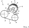
1 zeigt ein Prinzipbild eines erfindungsgemäßen Riementriebs in axialer Ansicht auf die Antriebsachse und die Drehachsen der Riemenscheiben; -
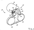
2 zeigt ein Prinzipbild eines erfindungsgemäßen Riementriebs in abgewandelter Ausführung in 3D-Darstellung; -
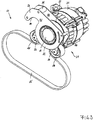
3 zeigt einen erfindungsgemäßen Riementrieb in Teildarstellung (ohne weitere Spannrollen) in 3D-Darstellung; -
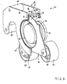
4 zeigt die Riemenspannvorrichtung des Riementriebs nach3 in geschnittener 3D-Darstellung; -
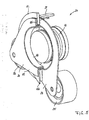
5 eine Riemenspannvorrichtung in abgewandelter Ausführung in geschnittener 3D-Darstellung.
-
1 shows a schematic diagram of a belt drive according to the invention in an axial view of the drive axis and the axes of rotation of the pulleys; -
2nd shows a schematic diagram of a belt drive according to the invention in a modified version in 3D; -
3rd shows a belt drive according to the invention in partial representation (without further tensioning rollers) in a 3D representation; -
4th shows the belt tensioner of the belt drive3rd in a cut 3D representation; -
5 a belt tensioner in a modified version in a sectional 3D representation.
In
Die Antriebsscheibe
Die gesamte Spannvorrichtung
In
In
In
Es ist die hier ohne Anbindung an den Startergenerator dargestellte Antriebsscheibe
In
BezugszeichenlisteReference symbol list
- 1111
- RiementriebBelt drive
- 1212
- AntriebsscheibeTraction sheave
- 1313
- RiemenscheibePulley
- 1414
- RiemenscheibePulley
- 1515
- Riemen belt
- 2121st
- RiemenspannvorrichtungBelt tensioner
- 2222
- Gehäusecasing
- 2323
- SpannarmArm
- 2424th
- SpannarmArm
- 2525th
- SpannrolleIdler pulley
- 2626
- SpannrolleIdler pulley
- 2727th
- DruckfederCompression spring
- 2828
- GegenarmCounter arm
- 2929
- BefestigungsarmMounting arm
- 3030th
- 3131
- AnlassergeneratorStarter generator
- 3232
- Blechsheet
- 3333
- Blechsheet
- 3434
- DistanzstückSpacer
- 3535
- DistanzstückSpacer
- 3636
- Distanzstück Spacer
- 4242
- Bundbuchsecollar bushing
- 4343
- Bundbuchsecollar bushing
- 4444
- L-ProfilL profile
- 4545
- L-ProfilL profile
- 4646
- Bundbuchsecollar bushing
- 4747
- Bundbuchsecollar bushing
- 4848
- L-ProfilL profile
- 4949
- L-ProfilL profile
- 5050
- 5151
- VerbinderInterconnects
- 5252
- RollenzapfenRoller pin
- 5353
- AbstütznaseSupport nose
- 5454
- U-ProfilbuchseU-profile socket
- 5555
- U-ProfilU profile
- 5656
- U-Profilbuchse !U-profile socket!
- 5757
- L-Profil innenL-profile inside
- 5858
- L-Profil außenL-profile outside
Claims (14)
Priority Applications (7)
| Application Number | Priority Date | Filing Date | Title |
|---|---|---|---|
| DE102008025552.1A DE102008025552B4 (en) | 2008-05-28 | 2008-05-28 | Belt tensioner for starter-generator application |
| AT09006897T ATE522746T1 (en) | 2008-05-28 | 2009-05-22 | BELT TENSIONER FOR STARTER GENERATOR APPLICATION |
| EP09006897A EP2128489B1 (en) | 2008-05-28 | 2009-05-22 | Belt tensioning device for starter-generator application |
| ES09006897T ES2370101T3 (en) | 2008-05-28 | 2009-05-22 | BELT TENSIONER DEVICE FOR APPLICATION IN STAND-GENERATOR. |
| JP2009129308A JP5634685B2 (en) | 2008-05-28 | 2009-05-28 | Belting device for starter / generator |
| US12/455,110 US8821328B2 (en) | 2008-05-28 | 2009-05-28 | Belt tensioning device for being used with a starter generator |
| US14/474,430 US9551402B2 (en) | 2008-05-28 | 2014-09-02 | Belt tensioning device for being used with a starter generator |
Applications Claiming Priority (1)
| Application Number | Priority Date | Filing Date | Title |
|---|---|---|---|
| DE102008025552.1A DE102008025552B4 (en) | 2008-05-28 | 2008-05-28 | Belt tensioner for starter-generator application |
Publications (2)
| Publication Number | Publication Date |
|---|---|
| DE102008025552A1 DE102008025552A1 (en) | 2009-12-03 |
| DE102008025552B4 true DE102008025552B4 (en) | 2020-06-10 |
Family
ID=40996819
Family Applications (1)
| Application Number | Title | Priority Date | Filing Date |
|---|---|---|---|
| DE102008025552.1A Active DE102008025552B4 (en) | 2008-05-28 | 2008-05-28 | Belt tensioner for starter-generator application |
Country Status (6)
| Country | Link |
|---|---|
| US (2) | US8821328B2 (en) |
| EP (1) | EP2128489B1 (en) |
| JP (1) | JP5634685B2 (en) |
| AT (1) | ATE522746T1 (en) |
| DE (1) | DE102008025552B4 (en) |
| ES (1) | ES2370101T3 (en) |
Families Citing this family (81)
| Publication number | Priority date | Publication date | Assignee | Title |
|---|---|---|---|---|
| JP3120299B2 (en) | 1992-03-26 | 2000-12-25 | 日本ソリッド株式会社 | Wall structure with cushioning material attached |
| JP4930281B2 (en) * | 2007-08-23 | 2012-05-16 | マツダ株式会社 | Belt tensioner and belt replacement method in belt tensioner |
| DE102010006418A1 (en) * | 2010-02-01 | 2011-08-04 | Schaeffler Technologies GmbH & Co. KG, 91074 | Traction drive of an internal combustion engine |
| DE102010010834B4 (en) * | 2010-03-10 | 2020-02-13 | Dr. Ing. H.C. F. Porsche Aktiengesellschaft | Clamping device for an aggregate drive on a machine |
| DE102011082764A1 (en) | 2010-10-13 | 2012-04-19 | Schaeffler Technologies Gmbh & Co. Kg | Clamping device for a traction mechanism drive of an internal combustion engine |
| DE102011082330B4 (en) * | 2011-08-12 | 2014-08-07 | Schaeffler Technologies Gmbh & Co. Kg | Clamping device for a belt drive and electric machine with such a clamping device |
| DE102011053869B4 (en) | 2011-09-22 | 2020-03-26 | Muhr Und Bender Kg | Belt tensioning device for a belt drive and assembly arrangement with belt tensioning device |
| DE102011084680B3 (en) | 2011-10-18 | 2012-11-22 | Schaeffler Technologies AG & Co. KG | Clamping device for belt drive of electric machine e.g. generator, has bearing support with bearing point on which slide bearing is supported with respect to side of drive wheel of housing |
| DE102011088652A1 (en) | 2011-12-15 | 2013-06-20 | Schaeffler Technologies AG & Co. KG | Clamping device for a belt drive |
| CN103195887B (en) * | 2012-01-05 | 2015-11-18 | 沈阳新松机器人自动化股份有限公司 | There is the belt wheel mechanism of tensioning mechanism |
| US9341243B2 (en) | 2012-03-29 | 2016-05-17 | Litens Automotive Partnership | Tensioner and endless drive arrangement |
| FR2991420B1 (en) * | 2012-05-30 | 2014-07-11 | Peugeot Citroen Automobiles Sa | ASSEMBLY COMPRISING AN ALTERNOMETER HOUSING |
| DE102012209028A1 (en) | 2012-05-30 | 2013-12-05 | Schaeffler Technologies AG & Co. KG | Tensioning device for belt drive, has tension rollers in which one roller is mounted on tensioning arm and other roller is stationarily supported on tensioner housing |
| DE102012210557A1 (en) | 2012-06-22 | 2013-12-24 | Bayerische Motoren Werke Aktiengesellschaft | Belt tensioning device for auxiliary unit belt drive for vehicle combustion engine, has tensioner housing connected with housing of auxiliary unit such that transmission of rotational torque occurs only in rotation direction of pulleys |
| DE102012212730B3 (en) * | 2012-07-19 | 2013-12-12 | Schaeffler Technologies AG & Co. KG | Belt tensioner for auxiliary unit belt drive of internal combustion engine, has tensioning rollers on curved midpoint trajectory guided into working area of tensioner, where center of curvature of trajectory runs within diameter of pulley |
| CN104884842B (en) * | 2012-12-26 | 2017-11-14 | 利滕斯汽车合伙公司 | track tensioner assembly |
| DE102013002993A1 (en) * | 2013-02-22 | 2014-08-28 | Schaeffler Technologies Gmbh & Co. Kg | Starter Generator - Belt Tensioner |
| US8821327B1 (en) * | 2013-02-26 | 2014-09-02 | GM Global Technology Operations LLC | Engine accessory mount for improved stretch belt installation |
| DE102013203957B3 (en) * | 2013-03-08 | 2014-02-13 | Schaeffler Technologies AG & Co. KG | Belt tensioner for mounting at generator of aggregate drive of internal combustion engine, has lever comprising steel core with aluminum sleeve, which encloses outside of cavity and completely encloses running part of core within bearing |
| DE102013102562B4 (en) | 2013-03-13 | 2021-05-27 | Muhr Und Bender Kg | Use of a spring in a belt tensioning device, belt tensioning device and assembly arrangement |
| DE102013206010B3 (en) * | 2013-04-05 | 2014-08-07 | Schaeffler Technologies Gmbh & Co. Kg | Belt tensioning device for attachment to generator of accessory drive of internal combustion engine, has linear tensioner, which is hinged with its first end on one clamping lever and with its second end on another clamping lever |
| FR3005129A1 (en) * | 2013-04-30 | 2014-10-31 | Peugeot Citroen Automobiles Sa | DEVICE FOR TRANSFERRING A TORQUE BETWEEN AN ELECTRIC MACHINE AND A THERMAL MOTOR |
| WO2014186961A1 (en) * | 2013-05-22 | 2014-11-27 | 华为技术有限公司 | User equipment network accessing method, and access device |
| JP6252206B2 (en) * | 2014-01-29 | 2017-12-27 | 株式会社デンソー | Transmission system |
| US9920819B2 (en) * | 2014-02-06 | 2018-03-20 | Gates Corporation | Tensioner |
| US9140338B2 (en) * | 2014-02-06 | 2015-09-22 | Gates Corporation | Tensioner |
| US20150300462A1 (en) * | 2014-02-06 | 2015-10-22 | Gates Corporation | Tensioner |
| DE102014203952A1 (en) * | 2014-03-05 | 2015-09-10 | Schaeffler Technologies AG & Co. KG | tensioner |
| DE102014207210A1 (en) | 2014-04-15 | 2015-10-15 | Schaeffler Technologies AG & Co. KG | Clamping device for a belt drive |
| US20150308545A1 (en) * | 2014-04-28 | 2015-10-29 | The Gates Corporation | Orbital tensioner |
| US10240664B2 (en) | 2014-06-20 | 2019-03-26 | Litens Automotive Partnership | Tensioner with hydraulic locking feature |
| JP6503385B2 (en) | 2014-06-26 | 2019-04-17 | リテンズ オートモーティヴ パートナーシップ | Track tensioner assembly |
| JP6452191B2 (en) * | 2014-06-26 | 2019-01-16 | ダイハツ工業株式会社 | Internal combustion engine for vehicles |
| US9759293B2 (en) | 2014-10-21 | 2017-09-12 | Litens Automotive Partnership | Endless drive arrangement and improved two-armed tensioning system for same |
| EP3209901B1 (en) * | 2014-10-21 | 2022-04-20 | Litens Automotive Partnership | Endless drive arrangement and improved two-armed tensioning system for same |
| DE102014117094A1 (en) * | 2014-11-21 | 2016-05-25 | Muhr Und Bender Kg | Belt tensioner |
| JP6073285B2 (en) | 2014-12-05 | 2017-02-01 | 株式会社デンソー | Control device |
| WO2016098051A1 (en) | 2014-12-17 | 2016-06-23 | Dayco Europe S.R.L. | Tensioner for an accessory drive |
| WO2016098052A1 (en) * | 2014-12-17 | 2016-06-23 | Dayco Europe S.R.L. | Tensioner comprising an improved damping device |
| HUE057086T2 (en) | 2015-02-06 | 2022-04-28 | Litens Automotive Inc | Endless drive arrangement for hybrid vehicle using two-armed tensioner with non-orbiting arms |
| FR3032746B1 (en) | 2015-02-16 | 2018-08-03 | Valeo Equipements Electriques Moteur | ROTATING ELECTRIC MACHINE WITH BELT RECEIVING PULLEY AND BELT TENSION ADJUSTING DEVICE |
| KR101664672B1 (en) * | 2015-03-20 | 2016-10-10 | 현대자동차주식회사 | Belt auto-tensioner for engine |
| US10393238B2 (en) | 2015-04-02 | 2019-08-27 | Litens Automotive Partnership | Accessory drive tensioner with improved arrangement of tensioner arm and biasing member |
| DE102015210002B4 (en) | 2015-06-01 | 2020-03-26 | Schaeffler Technologies AG & Co. KG | Belt tensioner |
| DE102015212084A1 (en) | 2015-06-29 | 2016-12-29 | Schaeffler Technologies AG & Co. KG | Pendulum clamp with specifically adjustable damping |
| DE102015212927A1 (en) | 2015-07-10 | 2017-01-12 | Schaeffler Technologies AG & Co. KG | Pendulum clamp with adjustable axial play and belt drive |
| DE102015215421A1 (en) * | 2015-08-13 | 2017-02-16 | Schaeffler Technologies AG & Co. KG | Ring tensioner with identical ring lever bearing |
| DE102015215812B4 (en) * | 2015-08-19 | 2020-03-26 | Schaeffler Technologies AG & Co. KG | Belt tensioner |
| CN105240471B (en) * | 2015-10-28 | 2018-02-13 | 安徽江淮汽车集团股份有限公司 | A kind of two-way tensioning apparatus |
| CN105179619B (en) * | 2015-10-28 | 2017-07-04 | 安徽江淮汽车集团股份有限公司 | A kind of two-way tensioning apparatus |
| DE102015222238B4 (en) * | 2015-11-11 | 2020-11-12 | Schaeffler Technologies AG & Co. KG | Noise-dampened self-aligning bearings for decoupling belt tensioning units |
| DE102015222203B4 (en) * | 2015-11-11 | 2020-03-12 | Schaeffler Technologies AG & Co. KG | Backlash-free pendulum bearing on the decoupling clamp |
| FR3049784B1 (en) * | 2016-03-30 | 2019-05-03 | Valeo Equipements Electriques Moteur | IMPROVED FRONT FLANGE OF ROTATING ELECTRICAL MACHINE AND ROTATING ELECTRIC MACHINE COMPRISING SUCH FLANGE |
| DE102016109320A1 (en) | 2016-05-20 | 2017-11-23 | Muhr Und Bender Kg | Bending spring made of fiber-reinforced plastic, belt tensioning device and method for producing the bending spring |
| WO2017205976A1 (en) | 2016-05-30 | 2017-12-07 | Litens Automotive Partnership | Endless drive arrangement and tensioning system for same |
| US9976634B2 (en) | 2016-07-06 | 2018-05-22 | Gates Corporation | Rotary tensioner |
| HUE058141T2 (en) * | 2016-08-11 | 2022-07-28 | Litens Automotive Inc | Endless drive arrangement with improved two-armed tensioning system |
| US11174921B2 (en) | 2016-09-13 | 2021-11-16 | Litens Automotive Partnership | V tensioner and endless drive arrangement |
| DE102016217933B4 (en) | 2016-09-20 | 2020-06-04 | Schaeffler Technologies AG & Co. KG | Belt tensioner |
| CN108005782A (en) * | 2016-11-02 | 2018-05-08 | 荣成华泰汽车有限公司 | Belt wheel guide frame and engine |
| KR20180109532A (en) * | 2017-03-28 | 2018-10-08 | 주식회사 만도 | Actuator |
| DE102017107047A1 (en) | 2017-03-31 | 2018-10-04 | Muhr Und Bender Kg | Clamping device with adjusting mechanism and method for adjusting the torque of the clamping device |
| IT201700053588A1 (en) * | 2017-05-17 | 2018-11-17 | Dayco Europe Srl | TENSIONER FOR A TRANSMISSION ACCESSORIES OF A MOTOR VEHICLE |
| JP6803807B2 (en) | 2017-06-30 | 2020-12-23 | 株式会社クボタ | Industrial hybrid engine |
| DE102017116000A1 (en) * | 2017-07-17 | 2019-01-17 | Muhr Und Bender Kg | Belt tensioner |
| US10962092B2 (en) | 2017-09-08 | 2021-03-30 | Gates Corporation | Tensioner and method |
| DE102017217645A1 (en) | 2017-10-05 | 2019-04-11 | Bayerische Motoren Werke Aktiengesellschaft | Belt tensioner |
| DE102017124783B3 (en) * | 2017-10-24 | 2019-03-21 | Muhr Und Bender Kg | jig |
| DE102018120933B4 (en) | 2017-10-27 | 2024-08-14 | Schaeffler Technologies AG & Co. KG | Belt tensioner |
| US10746264B2 (en) | 2017-11-16 | 2020-08-18 | Gates Corporation | Rotary tensioner |
| US10876606B2 (en) | 2018-03-13 | 2020-12-29 | Gates Corporation | Orbital tensioner |
| US10774906B2 (en) | 2018-03-27 | 2020-09-15 | Gates Corporation | Tensioner |
| FR3080233B1 (en) * | 2018-04-17 | 2021-04-16 | Valeo Equip Electr Moteur | SET INCLUDING A ROTATING ELECTRIC MACHINE AND A BELT TENSIONER |
| KR102552020B1 (en) * | 2018-10-19 | 2023-07-05 | 현대자동차 주식회사 | Tensioner for hybrid electric vehicle |
| DE102019115746A1 (en) * | 2019-06-11 | 2020-12-17 | Schaeffler Technologies AG & Co. KG | Drawbar tensioning device for a drawbar drive |
| US11333223B2 (en) | 2019-08-06 | 2022-05-17 | Gates Corporation | Orbital tensioner |
| DE102020004335A1 (en) * | 2020-07-20 | 2022-01-20 | Muhr Und Bender Kg | Belt tensioning device and belt drive with such a belt tensioning device |
| WO2022034820A1 (en) * | 2020-08-11 | 2022-02-17 | 三菱自動車工業株式会社 | Belt transmission device |
| US11906108B1 (en) * | 2022-07-29 | 2024-02-20 | Deere & Company | Belt trap with integrated tensioner |
| IT202300003939A1 (en) * | 2023-03-03 | 2024-09-03 | Fca Italy Spa | “INTERNAL COMBUSTION ENGINE WITH BSG TYPE MOTOR GENERATOR AND RELATED TENSIONER DEVICE” |
| IT202300008754A1 (en) * | 2023-05-03 | 2024-11-03 | Fca Italy Spa | INTERNAL COMBUSTION ENGINE WITH BSG TYPE MOTOR GENERATOR |
Citations (8)
| Publication number | Priority date | Publication date | Assignee | Title |
|---|---|---|---|---|
| US4758208A (en) | 1987-07-13 | 1988-07-19 | General Motors Corporation | Automatic belt tensioner for vehicle combined starter-generator |
| DE19849886A1 (en) | 1998-10-29 | 2000-05-11 | Bosch Gmbh Robert | Belt drive, especially in internal combustion engines for driving auxiliary units of a vehicle |
| DE19926615A1 (en) | 1999-06-11 | 2000-12-14 | Schaeffler Waelzlager Ohg | Tensioning device for traction devices such as belts or chains |
| EP1420192A2 (en) * | 2002-11-16 | 2004-05-19 | Bayerische Motoren Werke Aktiengesellschaft | Tensioning device for a transmission with endless flexible member of an auxiliary apparatus |
| WO2004059192A1 (en) * | 2002-12-30 | 2004-07-15 | Dayco Europe S.R.L. Con Unico Socio | A two-arm belt tensioner for a belt drive |
| DE10321801A1 (en) * | 2003-01-10 | 2004-07-29 | Muhr Und Bender Kg | Belt tensioner |
| EP1464871A1 (en) | 2003-04-02 | 2004-10-06 | DAYCO EUROPE S.r.l. | Two-arm belt tensioner |
| DE102005039719A1 (en) | 2005-08-23 | 2007-03-22 | Schaeffler Kg | Tensioning system for traction mechanism drive, has two tensioning devices supported rotatably around rotation axis, where two clamping devices are movably coupled with one another for simultaneously aligned movement |
Family Cites Families (22)
| Publication number | Priority date | Publication date | Assignee | Title |
|---|---|---|---|---|
| US976115A (en) * | 1910-11-15 | Burke Electric Company | Power mechanism. | |
| US315735A (en) * | 1885-04-14 | Device for transmitting power | ||
| US952156A (en) * | 1908-11-02 | 1910-03-15 | Benjamin Trewhella | Roller-grip for band-gearing. |
| US1433958A (en) * | 1921-05-04 | 1922-10-31 | Laughton Harold | Power-transmission belt gearing |
| US2766417A (en) * | 1952-08-09 | 1956-10-09 | Nolan Company | Belt drive actuated motor controlling switch mechanism |
| DE2524605A1 (en) * | 1975-06-03 | 1976-12-23 | Heinz Peter Dipl Brandstetter | DEVICE FOR MEASURING MECHANICAL WORK AND POWER |
| US4034821A (en) * | 1976-06-09 | 1977-07-12 | Stoddard Richard B | Motorcycle chain drive |
| US4112767A (en) * | 1977-04-04 | 1978-09-12 | General Electric Company | Clothes dryer variable speed drive system |
| AT354271B (en) * | 1978-03-07 | 1979-12-27 | Leitner Horst | CHAIN DRIVE FOR SWING ARM MOUNTED REAR WHEELS OF MOTORCYCLES |
| US4564098A (en) * | 1979-06-21 | 1986-01-14 | Hormann Kg | Drive assembly for door operator |
| JPH01143454U (en) * | 1988-03-28 | 1989-10-02 | ||
| DE4343429C2 (en) * | 1993-12-18 | 1999-08-12 | Schaeffler Waelzlager Ohg | Tensioning device for a belt or chain drive |
| US5443424A (en) * | 1994-10-20 | 1995-08-22 | Dayco Products, Inc. | Belt tensioner and method of making the same |
| AU2001296474A1 (en) * | 2000-10-03 | 2002-04-15 | The Gates Corporation | Accessory and motor/generator belt drive tensioner |
| US7163478B2 (en) * | 2001-12-12 | 2007-01-16 | Dayco Products, Llc | Belt tensioner having an automatically adjustable travel stop |
| US6689001B2 (en) * | 2001-12-12 | 2004-02-10 | Dayco Products, Llc | Adaptive belt tensioner system for control of reversible torque load pulley |
| US6830524B2 (en) * | 2002-05-23 | 2004-12-14 | General Motors Corporation | Crank drive belt system with triple pulley tensioner |
| EP1437528B1 (en) | 2003-01-10 | 2010-03-10 | Muhr und Bender KG | Belt tensioner |
| US20050181901A1 (en) * | 2004-02-13 | 2005-08-18 | Chang-Hyun Shin | Double action belt tensioner |
| US7892125B2 (en) * | 2006-09-15 | 2011-02-22 | Xerox Corporation | Simplified and adaptable flexible drive tensioner |
| US9133762B2 (en) * | 2009-09-18 | 2015-09-15 | GM Global Technology Operations LLC | Drive belt tensioner for motor generator unit |
| DE102013102562B4 (en) * | 2013-03-13 | 2021-05-27 | Muhr Und Bender Kg | Use of a spring in a belt tensioning device, belt tensioning device and assembly arrangement |
-
2008
- 2008-05-28 DE DE102008025552.1A patent/DE102008025552B4/en active Active
-
2009
- 2009-05-22 EP EP09006897A patent/EP2128489B1/en active Active
- 2009-05-22 ES ES09006897T patent/ES2370101T3/en active Active
- 2009-05-22 AT AT09006897T patent/ATE522746T1/en active
- 2009-05-28 US US12/455,110 patent/US8821328B2/en active Active
- 2009-05-28 JP JP2009129308A patent/JP5634685B2/en active Active
-
2014
- 2014-09-02 US US14/474,430 patent/US9551402B2/en active Active
Patent Citations (8)
| Publication number | Priority date | Publication date | Assignee | Title |
|---|---|---|---|---|
| US4758208A (en) | 1987-07-13 | 1988-07-19 | General Motors Corporation | Automatic belt tensioner for vehicle combined starter-generator |
| DE19849886A1 (en) | 1998-10-29 | 2000-05-11 | Bosch Gmbh Robert | Belt drive, especially in internal combustion engines for driving auxiliary units of a vehicle |
| DE19926615A1 (en) | 1999-06-11 | 2000-12-14 | Schaeffler Waelzlager Ohg | Tensioning device for traction devices such as belts or chains |
| EP1420192A2 (en) * | 2002-11-16 | 2004-05-19 | Bayerische Motoren Werke Aktiengesellschaft | Tensioning device for a transmission with endless flexible member of an auxiliary apparatus |
| WO2004059192A1 (en) * | 2002-12-30 | 2004-07-15 | Dayco Europe S.R.L. Con Unico Socio | A two-arm belt tensioner for a belt drive |
| DE10321801A1 (en) * | 2003-01-10 | 2004-07-29 | Muhr Und Bender Kg | Belt tensioner |
| EP1464871A1 (en) | 2003-04-02 | 2004-10-06 | DAYCO EUROPE S.r.l. | Two-arm belt tensioner |
| DE102005039719A1 (en) | 2005-08-23 | 2007-03-22 | Schaeffler Kg | Tensioning system for traction mechanism drive, has two tensioning devices supported rotatably around rotation axis, where two clamping devices are movably coupled with one another for simultaneously aligned movement |
Also Published As
| Publication number | Publication date |
|---|---|
| JP5634685B2 (en) | 2014-12-03 |
| EP2128489A3 (en) | 2010-03-24 |
| US8821328B2 (en) | 2014-09-02 |
| EP2128489B1 (en) | 2011-08-31 |
| JP2009287776A (en) | 2009-12-10 |
| DE102008025552A1 (en) | 2009-12-03 |
| ES2370101T3 (en) | 2011-12-12 |
| EP2128489A2 (en) | 2009-12-02 |
| US20090298631A1 (en) | 2009-12-03 |
| ATE522746T1 (en) | 2011-09-15 |
| US9551402B2 (en) | 2017-01-24 |
| US20150018148A1 (en) | 2015-01-15 |
Similar Documents
| Publication | Publication Date | Title |
|---|---|---|
| DE102008025552B4 (en) | Belt tensioner for starter-generator application | |
| DE102010045302B4 (en) | Drive belt tensioner for a motor / generator unit | |
| EP2557295B1 (en) | Tensioning device for a belt drive and electric machine with such a tensioning device | |
| EP1437528B1 (en) | Belt tensioner | |
| DE3200610A1 (en) | BELT TENSIONING DEVICE FOR A DRIVE BELT DRIVEN BY A MOTOR FOR AUXILIARY SENSORS OF MOTOR VEHICLES | |
| DE3852081T2 (en) | Belt tensioner with an increasingly curved trajectory. | |
| DE8510144U1 (en) | Belt tensioning device for the automatic tensioning of an endless drive belt | |
| DE112015002405B4 (en) | belt transmission system | |
| DE102018215451A1 (en) | Motorcycle with a tensioning device for tensioning a tension member and tensioning device for a motorcycle | |
| DE102008026064B4 (en) | Belt tensioner arrangement for a belt drive | |
| DE102004012395B4 (en) | Clamping unit for a unit operation | |
| DE10321801B4 (en) | Belt tensioning device | |
| DE3828719A1 (en) | BELT TENSIONER FOR TEXTILE MACHINES | |
| EP1245141B1 (en) | Working apparatus with pivotable working units | |
| DE102008058969B4 (en) | Traction device | |
| DE102015205273A1 (en) | Belt drive with coupled tension rollers | |
| DE102004041044A1 (en) | Pivot bearing of an aggregate | |
| DE102011088213A1 (en) | Instep arrangement for traction drive of accessory drive unit of internal combustion engine, has clamping unit to bias clamping elements through lever against traction unit, that is pivoted on associated end of lever | |
| DE102010010834A1 (en) | Clamping device for aggregate drive at machine, particularly internal combustion engine, comprises traction drive, which is formed as belt drive or chain drive with pulleys or chain wheels for traction drive | |
| DE102013100831B4 (en) | Device for the eradication of chain vibrations | |
| DE102016215056A1 (en) | Traction drive, in particular belt drive, for a hybrid powertrain of a motor vehicle | |
| EP1921345B1 (en) | Tensioner device tensioning a drive means and use of said device | |
| DE736407C (en) | Arrangement to achieve a constant belt tensioning force for belt-driven machines | |
| DE3030907A1 (en) | Tracked vehicle wheel elastically arranged on hub - has wheel rim attached to hub by bolt which is surrounded by bush having resilient rings vulcanised to outer surface | |
| DE10209723B4 (en) | Device for damping vibrations in traction drives |
Legal Events
| Date | Code | Title | Description |
|---|---|---|---|
| OP8 | Request for examination as to paragraph 44 patent law | ||
| R016 | Response to examination communication | ||
| R016 | Response to examination communication | ||
| R016 | Response to examination communication | ||
| R016 | Response to examination communication | ||
| R018 | Grant decision by examination section/examining division | ||
| R020 | Patent grant now final |