EP4005994A1 - Procédé de fabrication de ciment à partir d'une matière première aluminosilicate - Google Patents
Procédé de fabrication de ciment à partir d'une matière première aluminosilicate Download PDFInfo
- Publication number
- EP4005994A1 EP4005994A1 EP21209403.1A EP21209403A EP4005994A1 EP 4005994 A1 EP4005994 A1 EP 4005994A1 EP 21209403 A EP21209403 A EP 21209403A EP 4005994 A1 EP4005994 A1 EP 4005994A1
- Authority
- EP
- European Patent Office
- Prior art keywords
- etching
- effluent
- sio
- silicon
- molar ratio
- Prior art date
- Legal status (The legal status is an assumption and is not a legal conclusion. Google has not performed a legal analysis and makes no representation as to the accuracy of the status listed.)
- Granted
Links
Images

Classifications
-
- C—CHEMISTRY; METALLURGY
- C04—CEMENTS; CONCRETE; ARTIFICIAL STONE; CERAMICS; REFRACTORIES
- C04B—LIME, MAGNESIA; SLAG; CEMENTS; COMPOSITIONS THEREOF, e.g. MORTARS, CONCRETE OR LIKE BUILDING MATERIALS; ARTIFICIAL STONE; CERAMICS; REFRACTORIES; TREATMENT OF NATURAL STONE
- C04B12/00—Cements not provided for in groups C04B7/00 - C04B11/00
- C04B12/005—Geopolymer cements, e.g. reaction products of aluminosilicates with alkali metal hydroxides or silicates
-
- C—CHEMISTRY; METALLURGY
- C04—CEMENTS; CONCRETE; ARTIFICIAL STONE; CERAMICS; REFRACTORIES
- C04B—LIME, MAGNESIA; SLAG; CEMENTS; COMPOSITIONS THEREOF, e.g. MORTARS, CONCRETE OR LIKE BUILDING MATERIALS; ARTIFICIAL STONE; CERAMICS; REFRACTORIES; TREATMENT OF NATURAL STONE
- C04B7/00—Hydraulic cements
- C04B7/24—Cements from oil shales, residues or waste other than slag
-
- C—CHEMISTRY; METALLURGY
- C04—CEMENTS; CONCRETE; ARTIFICIAL STONE; CERAMICS; REFRACTORIES
- C04B—LIME, MAGNESIA; SLAG; CEMENTS; COMPOSITIONS THEREOF, e.g. MORTARS, CONCRETE OR LIKE BUILDING MATERIALS; ARTIFICIAL STONE; CERAMICS; REFRACTORIES; TREATMENT OF NATURAL STONE
- C04B28/00—Compositions of mortars, concrete or artificial stone, containing inorganic binders or the reaction product of an inorganic and an organic binder, e.g. polycarboxylate cements
-
- C—CHEMISTRY; METALLURGY
- C04—CEMENTS; CONCRETE; ARTIFICIAL STONE; CERAMICS; REFRACTORIES
- C04B—LIME, MAGNESIA; SLAG; CEMENTS; COMPOSITIONS THEREOF, e.g. MORTARS, CONCRETE OR LIKE BUILDING MATERIALS; ARTIFICIAL STONE; CERAMICS; REFRACTORIES; TREATMENT OF NATURAL STONE
- C04B28/00—Compositions of mortars, concrete or artificial stone, containing inorganic binders or the reaction product of an inorganic and an organic binder, e.g. polycarboxylate cements
- C04B28/006—Compositions of mortars, concrete or artificial stone, containing inorganic binders or the reaction product of an inorganic and an organic binder, e.g. polycarboxylate cements containing mineral polymers, e.g. geopolymers of the Davidovits type
-
- Y—GENERAL TAGGING OF NEW TECHNOLOGICAL DEVELOPMENTS; GENERAL TAGGING OF CROSS-SECTIONAL TECHNOLOGIES SPANNING OVER SEVERAL SECTIONS OF THE IPC; TECHNICAL SUBJECTS COVERED BY FORMER USPC CROSS-REFERENCE ART COLLECTIONS [XRACs] AND DIGESTS
- Y02—TECHNOLOGIES OR APPLICATIONS FOR MITIGATION OR ADAPTATION AGAINST CLIMATE CHANGE
- Y02P—CLIMATE CHANGE MITIGATION TECHNOLOGIES IN THE PRODUCTION OR PROCESSING OF GOODS
- Y02P40/00—Technologies relating to the processing of minerals
- Y02P40/10—Production of cement, e.g. improving or optimising the production methods; Cement grinding
Definitions
- the present invention relates to the field of the manufacture of cement. It finds a particularly advantageous application in the field of geopolymer cements.
- a commonly used cement is “Portland” cement composed of CaCO 3 -based rocks, sand and clay.
- Portland cement comes from a heavy and complex industry consisting in transforming limestone and clay in ovens at 1500°C in order to create clinker, the basic component of cement. The heat required for this transformation is generally generated by fossil fuels. This results in a significant release of carbon dioxide.
- the transformation of limestone into calcium oxide induces a significant release of carbon dioxide, chemical formula CO 2 . Under these conditions, it is estimated that the production of one tonne of cement emits between 750 kg and 950 kg of CO 2 .
- cements made from an aluminosilicate raw material and an alkaline solution rich in dissolved silica. These cements differ chemically from Portland cement in that the hardening of Portland cement is done by hydration of the tricalcium silicate of the clinker, whereas the setting of a geopolymer cement is done by polymerization of oligo-(sialate-siloxo) of an alkali metal, typically potassium or sodium, into poly(sialate-siloxo) of this alkali metal.
- An object of the present invention is therefore to provide a solution reducing the environmental impact of a cement manufacturing process from aluminosilicate raw material.
- the alkali metal silicate solution is recovered from an existing silicon industrial process, implementing a silicon etching and therefore an effluent from the etching of a silicon-based substrate.
- this process can be a process for treating the substrate in the field of photovoltaics, for example for the manufacture of photovoltaic cells based on silicon, and in particular photovoltaic cells made from a monocrystalline silicon substrate, or from microelectronics, for example for the manufacture of a microelectronic component. It is therefore not necessary to manufacture the alkali metal silicate solution for the reaction with the aluminosilicate raw material, unlike the existing solutions. Instead of consuming resources to form this solution, chemical waste from the silicon-based substrate etching industry is reinjected into this cement manufacturing process for recovery. The energy cost and resources needed to manufacture cement are reduced, and therefore the environmental impact of the cement manufacturing process is reduced.
- the process for manufacturing cement can be implemented in a process for manufacturing concrete.
- the method of making concrete may include making the cement according to the first aspect and mixing the cement and aggregates.
- Another aspect of the invention relates to a use of an effluent from the etching of a silicon-based substrate, formed from a solution of an alkali metal silicate, of formula SiO 2 : M 2 O, and having a SiO 2 /M 2 O molar ratio substantially greater than or equal to 0.8, and preferably substantially greater than or equal to 1.40, in a mixture with an aluminosilicate raw material, for the manufacture of cement.
- This aspect has the advantages described with respect to the first aspect.
- the silicon-based substrate from which the etching effluent is supplied is a silicon-based substrate forming or intended to form a photovoltaic cell or a microelectronic component.
- the method comprises, prior to mixing the aluminosilicate raw material with the etching effluent, a check that the SiO 2 /M 2 O molar ratio of the at least one etching effluent is greater than or equal to 0, 8, and preferably greater than or equal to 1.40.
- the verification is carried out before or after supplying the at least one etching effluent.
- the verification of the SiO 2 /M 2 O molar ratio comprises a measurement of the SiO 2 /M 2 O molar ratio in the at least one etching effluent.
- the measurement of the SiO 2 /M 2 O molar ratio in the at least one etching effluent may be prior to supplying the at least one etching effluent.
- the verification comprises, following the measurement of the SiO 2 /M 2 O molar ratio, a modification of the at least one etching effluent so that the SiO 2 /M 2 O molar ratio reaches a determined value.
- the effluent can be modified so that the SiO 2 /M 2 O molar ratio is greater than 0.8, preferably 1.40, if it was not previously.
- the effluent can be modified so that the SiO 2 /M 2 O molar ratio has a determined value greater than 0.8, preferably 1.40.
- the repeatability of the process can be improved.
- the effluent can be adapted according to the needs of a cement manufacturer, for example with a view to obtaining particular properties of the cement.
- the measurement of the SiO 2 /M 2 O molar ratio is carried out in an etching bath, during a process for etching the silicon-based substrate, by equipment for regulating the etching bath.
- the measurement of this ratio can thus be carried out directly during the etching process, in particular so as to identify whether the etching bath is suitable for being supplied for the manufacture of cement.
- the silicon etching process comprising a plurality of successive etchings of silicon-based substrates in the etching bath, several measurements of the SiO 2 /M 2 O molar ratio are carried out during the plurality of successive etchings.
- a measurement is carried out at regular intervals during the plurality of successive etchings, and preferably between each etching. The measurement of this ratio can thus be carried out directly along the course of the etching process, in particular so as to identify when the etching bath is suitable for being supplied for the manufacture of cement.
- the modification of the at least one etching effluent comprises an adjustment of the relative molar concentrations between the silicate and the monovalent metal M.
- the modification of the at least one etching effluent comprises the combination of a plurality of distinct etching effluents.
- the pH of the at least one etching effluent is greater than 9, and preferably greater than 12.
- the amount of silicate dissolved in the effluent can be maximized.
- the SiO 2 /M 2 O molar ratio is preferably less than or equal to 3.
- the etching effluent presents a lower chemical risk during handling and transport
- the aluminosilicate raw material is chosen from natural minerals such as kaolinite or clays, metallurgical slags, fly ash, silica fume, volcanic tuffs and mining residues.
- the aluminosilicate raw material comes from a rejection of an industrial process.
- the aluminosilicate raw material and the etching effluent being industrial process waste recovered in this cement manufacturing process, the environmental impact of the process is further reduced.
- the silicon-based substrate from which the etching effluent is supplied is a substrate in crystalline silicon and more particularly in monocrystalline silicon.
- the silicon-based substrate forms or is intended to form a photovoltaic cell, for example a silicon-based photovoltaic cell, for example of technology of the homojunction or heterojunction type, or a microelectronic component.
- a parameter "substantially equal/greater/less than” a given value that this parameter is equal/greater/less than the given value, to within plus or minus 10%, or even to within plus or minus 5% of this value.
- compound or material “based” on a material A means a compound or material comprising this material A, and possibly other materials.
- An alkali metal generally designates a metallic element from the first column of the periodic table of chemical elements, preferably potassium K or sodium Na.
- the molar ratio i/j between two compounds i and j denotes the ratio of the amount of material in moles of compound i to the amount of material in moles of compound j.
- the substrate 2 is exposed to reagents from an etching bath 4, chosen to react with the silicon and thus shape the surface of the substrate .
- an etching bath 4 chosen to react with the silicon and thus shape the surface of the substrate .
- the silicon is typically oxidized to silica, with the chemical formula SiO 2 and then etched 140.
- the etching bath 4 becomes loaded with dissolved silica to form the etching effluent.
- the etching bath becomes loaded with dissolved silica as the etching 140 of a plurality of substrates 2 progresses, as will be seen below.
- the effluent comprises at least one type, and for example several types of alkali metal silicates M dissolved in solution.
- the solution is at least partly aqueous, and preferably the solution is an aqueous solution of at least one dissolved alkali metal silicate M.
- Undissolved alkali metal silicate has the chemical formula SiO 2 : M 2 O.
- the alkali metal can vary depending on the reagents used in the etching bath.
- the alkali metal M is preferably potassium (K) or sodium (Na).
- the alkali metal silicate is therefore preferably a potassium silicate, or a sodium silicate.
- the alkali metal oxide M 2 O can be dissolved in an alkali metal hydroxide, of formula MOH, according to the following chemical reaction: M 2 O + H 2 O ⁇ 2 M + + 2 OH - .
- Silica can be dissolved according to the following chemical reaction: SiO 2 (s) + 2 H 2 O ⁇ Si(OH) 4 (aq) .
- Si(OH) 4 is converted into one or other of the species of the conjugate acid/base pairs H 3 SiO 4 - and H 2 SiO 4 2- .
- dissolved silica designates all the species comprising the element silicon, resulting from its oxidation into silica and its dissolution in the etching bath.
- the measurement of the species dissolved in solution makes it possible to find by equivalence the relative quantities of dissolved SiO 2 and M 2 O and therefore the SiO 2 /M 2 O molar ratio in solution.
- the etching effluent may be mixed 13 with a supplied aluminosilicate raw material 12. During this mixing 13, the alkali metal silicate reacts with the aluminosilicate raw material to form the geopolymer cement.
- the etching effluent has a SiO 2 /M 2 O molar ratio greater than or equal to 0.8 and preferably greater than or equal to 1.40. These minimum values of the molar ratio make it possible to ensure that a cement having satisfactory mechanical properties is obtained. More preferably still, the SiO 2 /M 2 O molar ratio may be greater than or equal to 1.45.
- the method 1 can include a verification 11 of the SiO 2 /M 2 O molar ratio. This verification 11 can in particular be done for check that this SiO 2 /M 2 O molar ratio is greater than or equal to the aforementioned values. This verification 11 can be carried out prior to the mixing 13, and/or prior to the supply 10 of the etching effluent.
- the value of the SiO 2 /M 2 O molar ratio can be adapted 111 according to the nature of the aluminosilicate raw material.
- the SiO 2 /M 2 O molar ratio may preferably be less than 4, preferably less than 3.
- the effluent is considered chemically of little danger for an operator. The transport of the effluent and its handling in process 1 are thus facilitated. In addition, the effluent is then more stable, which facilitates the conservation of the effluent.
- the amount of silica that can be dissolved in the effluent can be optimized.
- the pH of the etching effluent is greater than or equal to 9.
- the molar silica concentration can reach at least 10 -3 mol/L.
- the pH of the etching effluent is greater than or equal to 12.
- the molar silica concentration can reach at least 0.5 mol/L.
- Process 1 may comprise a measurement 110' of the pH of the etching effluent, and an adjustment 111 of the pH of the effluent to reach a determined pH value.
- the measurement 110' and/or the adjustment 111 can be carried out prior to the mixing 13, and/or prior to the supply 10 of the etching effluent.
- the etching effluent can be buffered to avoid variations in pH which can lead to a modification of the dissolution balances, and in particular a precipitation of the dissolved silica.
- At least one aluminosilicate raw material may be provided 12 to make the cement.
- Several aluminosilicate raw materials can be supplied 12 and mixed 13 with the effluent, for example to modulate the properties of the cement obtained.
- the aluminosilicate raw material includes silicates in which silicon atoms are replaced by aluminum atoms.
- the aluminosilicate raw material can be chosen from natural minerals such as kaolinite or clays, or even volcanic tuffs.
- the aluminosilicate raw material can come from an industrial process.
- the aluminosilicate raw material and the etching effluent can both come from industrial processes, the waste from which is therefore recovered by the manufacture of cement according to process 1.
- Concerning the aluminosilicate raw material there is therefore no no additional mining cost. The energy and resources needed to manufacture cement, as well as CO 2 emissions, are still limited. The environmental impact of Process 1 is further reduced.
- the aluminosilicate raw material can come from metallurgical slag, such as metallurgical slag, and more particularly blast furnace slag.
- the aluminosilicate raw material is a granulated and ground blast furnace slag.
- the aluminosilicate raw material can be fly ash, generally resulting from the combustion of anthracite or bituminous coal, or even lignite or sub-bituminous coal.
- the aluminosilicate raw material can be fumed silica, usually produced from the production of silicon by quartz reduction or from the production of ferrosilicon alloys.
- the aluminosilicate raw material can come from mining residues.
- the aluminosilicate raw material and the etching effluent can be mixed in variable proportions, in particular depending on the nature of the aluminosilicate raw material and the desired properties of the cement.
- the aluminosilicate raw material can represent at least 70% of the mixture 13.
- the etching effluent, optionally supplemented with water, can represent the rest of the mixture.
- the mixture 13 can comprise from 80 to 90% of slag for 10 to 20% of etching effluent.
- the method can comprise a measurement 110 of this ratio.
- the measurement 110 can comprise a measurement of the quantity of silica dissolved in the effluent, and of the equivalent quantity of M 2 O from the quantity of the alkali metal hydroxide M dissolved in the effluent.
- This measurement can be carried out prior to the mixing 13, and/or prior to the supply 10 of the etching effluent.
- This measurement can be performed on a sample taken from the etching effluent, or directly from the etching bath as will be seen below.
- These measurements can be carried out by any means known to those skilled in the art.
- the amount of dissolved silica can be measured by a total silica assay.
- Optical spectra analysis techniques can also be envisaged.
- method 1 can comprise a modification 111 of the etching effluent.
- This modification 111 can comprise an adjustment of the relative concentrations of SiO 2 and K 2 O, for example by dilution, by concentration and/or addition of one or more chemical species in the effluent. The adjustment is preferably made based on the measurement 110 performed.
- the modification 111 of the etching effluent can comprise a combination of a plurality of effluents, preferably whose SiO 2 /M 2 O molar ratio has been measured 110 beforehand.
- the management of the etching bath waste is thus optimized according to the chemical composition of the effluents, to obtain a particular SiO 2 /M 2 O molar ratio value. The cost and the environmental impact of the process are thus further minimized.
- the silicon etching manufacturer can check 11 the SiO 2 /M 2 O molar ratio and can modify 111 the etching effluent according to the needs of a cement manufacturer implementing process 1.
- the etching effluent(s) can be supplied to the cement manufacturer.
- the cement manufacturer performs, after receipt, verification 11 of the SiO 2 /M 2 O molar ratio.
- the cement manufacturer can then modify 111 the etching effluent according to the specific needs for the manufacture of a cement.
- These effluents can be supplied from the silicon etching industry to a third party.
- the third party can then supply the effluent(s) to the cement manufacturer.
- the third party may perform verification 11, and can modify 111 the effluent.
- One or more of the three actors can carry out the verification 11 and can modify 111 the etching effluent.
- a measurement 141 of the SiO 2 /M 2 O molar ratio can be performed by a silicon etching manufacturer.
- the silicon-based substrate 2 is etched in an etching bath 4. This process is now described with reference to the figure 2 .
- the damaged surface commonly referred to as a hardened zone, resulting from the cutting of the silicon wafers, is removed.
- This etching 140 of the surface of the silicon wafers is commonly abbreviated SDR, from English saw damaged removal, which can be translated by removal of the work-hardened zone, or SDE, from English saw damaged etching, which the can be translated by engraving of the work-hardened zone.
- This etching 140 is generally carried out in a bath of a basic solution of potassium hydroxide, of formula KOH, or of sodium hydroxide, of formula NaOH.
- the method 14 may comprise a second etching step 140 in a bath of a basic solution of potassium hydroxide or sodium hydroxide, generally called texturing.
- the texturing is configured to form pyramids on the surface of the substrate by the principle of anisotropic etching, according to the orientation of the crystalline planes of the silicon.
- the SDR step represents approximately two thirds of the mass of silicon removed from the substrates and the lifetime of an etching bath is often given for the treatment of approximately 60,000 substrates.
- the texturing step represents approximately one third of the mass of silicon removed from the substrates and the lifetime of the etching bath is approximately 20,000 to 30,000 substrates.
- each etching bath actually sees a succession of batches of substrates 2 pass.
- a bath strategy is associated in order to complete the etching bath. More particularly, potassium or sodium hydroxide and deionized and/or demineralized water are added between the passage of each batch.
- An adjustment of the volume of the bath is carried out in order to compensate on the one hand the part of liquid lost by transport of the substrates 2, the sufficient renewal of the chemical species responsible for the etching and the volume compensation of the bath to maintain a volume and a composition chemical sufficient for etching 140 of substrate 2.
- part of the etching bath 4 can be removed via a drain 40.
- Means 30 for adding water and/or reagents can then be actuated to complete the etching bath 4.
- the etching bath 4 is enriched with dissolved silica. The SiO 2 /M 2 O molar ratio can therefore change until the etching bath 4, and the resulting etching effluent, is suitable for use in the cement manufacturing process.
- a second strategy one can add 0.3 L of a KOH solution at 45% in mass fraction, relative to the total weight of the KOH solution, and 2.5 L of water between each batch. After the treatment of the 40th batch, a molar ratio of SiO 2 /K 2 O greater than 2 can be obtained. The final etching effluent, after passing all of the batches, can thus have a molar ratio of SiO 2 /K 2 O substantially equal to 2.7.
- a third strategy one can add 0.3 L of a KOH solution at 45% in mass fraction, relative to the total weight of the KOH solution, and 1 L of water between each batch. After the treatment of the 40th batch, a molar ratio of SiO 2 /K 2 O greater than 2 can be obtained. The final etching effluent, after passing all of the batches, can thus have a molar ratio of SiO 2 /K 2 O substantially equal to 2.5.
- a fourth strategy one can add 1 L of a KOH solution at 45% in mass fraction, relative to the total weight of the KOH solution, and 3 L of water between each batch. After the treatment of the 25th batch, a molar ratio of SiO 2 /K 2 O greater than 0.7 can be obtained. The final etching effluent, after passing all of the batches, can thus have a molar ratio of SiO 2 /K 2 O substantially equal to 0.9.
- the silicon etching process 140 and in particular the bath strategy, can be adapted to obtain a particular SiO 2 /M 2 O molar ratio.
- the silicon etching industry can implement verification 11 of the SiO 2 /M 2 O ratio in the etching bath and/or in the resulting effluent.
- the measurement 141 of the SiO 2 /M 2 O ratio can be carried out by measuring or sampling in the etching bath 4.
- the measurement 141 can be carried out at regular intervals during the etching process 140, for example after a determined number of batches of substrates have been treated.
- the etching process 140 can implement equipment 3 for regulating the etching bath 4. This equipment comprises the means 30 for adding reagents and/or water to the etching bath 4, actuated by one or more regulator(s) 31.
- the regulation equipment 3 can comprise a sensor 33, which can be connected to a processing unit 34 of the measured value.
- the sensor 33 can be placed in the etching bath 4.
- the sensor 33 is arranged on a recirculation loop of the etching bath 4, allowing online measurement on a fraction of the etching bath 4.
- the measurement 141 of the SiO 2 /M 2 O ratio can be carried out by measuring or sampling in an effluent from an etching bath 4 at the level of a recirculation loop of the etching bath 4, and /or after drainage as shown in picture 3 .
- the measurement 141 can for example be carried out by means of a sensor 33, which can be connected to a central processing unit 34 of the measured value.
- different etching effluents can be distributed according to their SiO 2 /M 2 O molar ratio.
- the etching effluents can be separated in different tanks 42, 43, possibly for subsequent modification 111 .
- the method 1 may further comprise, during or following the mixing 13 of the aluminosilicate raw material and the etching effluent, a mixture of these elements with a separate cement, for example a Portland cement.
- a separate cement for example a Portland cement.
- the cement or the mixture of cements obtained at the end of process 1 can be used for the manufacture of a concrete, in particular by a mixture with aggregates.
- the invention proposes a particularly advantageous solution for recovering etching effluent and a process making it possible to reduce the environmental impact of a process for manufacturing cement from raw material aluminosilicate
Landscapes
- Chemical & Material Sciences (AREA)
- Engineering & Computer Science (AREA)
- Ceramic Engineering (AREA)
- Organic Chemistry (AREA)
- Materials Engineering (AREA)
- Structural Engineering (AREA)
- Chemical Kinetics & Catalysis (AREA)
- Life Sciences & Earth Sciences (AREA)
- General Life Sciences & Earth Sciences (AREA)
- Inorganic Chemistry (AREA)
- Environmental & Geological Engineering (AREA)
- Geochemistry & Mineralogy (AREA)
- Geology (AREA)
- Silicon Compounds (AREA)
- Civil Engineering (AREA)
- Weting (AREA)
- Silicates, Zeolites, And Molecular Sieves (AREA)
- Dispersion Chemistry (AREA)
- Combustion & Propulsion (AREA)
Abstract
Description
- La présente invention concerne le domaine de la fabrication du ciment. Elle trouve pour application particulièrement avantageuse le domaine des ciments géopolymères.
- Il existe plusieurs types de ciment utilisés aujourd'hui, notamment comme liant pour la fabrication du béton. Un ciment couramment utilisé est le ciment « Portland » composé de roches à base CaCO3, de sable et d'argile. Le ciment Portland est issu d'une industrie lourde et complexe consistant à transformer le calcaire et l'argile dans des fours à 1500°C afin de créer le clinker, le composant de base du ciment. La chaleur nécessaire à cette transformation est généralement générée par des énergies fossiles. Il en résulte un dégagement important de dioxyde de carbone. En outre, la transformation du calcaire en oxyde de calcium induit un dégagement important de dioxyde de carbone, de formule chimique CO2. Dans ces conditions, on estime que la production d'une tonne de ciment émet entre 750 kg et 950 kg de CO2.
- Il existe des ciments dits « géopolymères » ou « alcali-activé », fabriqués à partir d'une matière première aluminosilicate, et d'une solution alcaline riche en silice dissoute. Ces ciments diffèrent chimiquement du ciment Portland en ce que le durcissement du ciment Portland se fait par hydratation du silicate tricalcique du clinker, alors que la prise d'un ciment géopolymère s'effectue par polymérisation d'oligo-(sialate-siloxo) d'un métal alcalin, typiquement de potassium ou de sodium, en poly(sialate-siloxo) de ce métal alcalin.
- Dans les ciments géopolymères, la transformation de la matière première aluminosilicate présente un coût énergétique et un rejet de CO2 bien inférieurs à ceux de la fabrication du ciment Portland. D'un point de vue économique et environnemental, ces ciments sont donc prometteurs comme alternative ou en mélange au ciment Portland.
- Il est notamment connu du document Ciments géopolymères, J. Davidovitz, Techniques de l'Ingénieur, 10 oct. 2014, un procédé de fabrication de ciment comprenant le mélange dans de l'eau d'une matière première aluminosilicate et de silicates de potassium ou de sodium, de formule SiO2 : M2O (M représentant ici le sodium ou le potassium) et présentant un rapport molaire SiO2/M2O compris entre 1,45 et 1,95. Ce procédé reste toutefois améliorable, notamment pour diminuer son impact environnemental.
- Un objet de la présente invention est donc de proposer une solution réduisant l'impact environnemental d'un procédé de fabrication de ciment à partir de matière première aluminosilicate.
- Les autres objets, caractéristiques et avantages de la présente invention apparaîtront à l'examen de la description suivante et des dessins d'accompagnement. Il est entendu que d'autres avantages peuvent être incorporés.
- Pour atteindre cet objectif, selon un premier aspect on prévoit un procédé de fabrication de ciment comprenant :
- la fourniture d'au moins un effluent de gravure d'un substrat à base de silicium comprenant un silicate d'un métal alcalin M dissout, de formule SiO2 : M2O, présentant un rapport molaire SiO2/M2O supérieur ou égal à 0,8, et de préférence supérieur ou égal à 1,40,
- la fourniture d'une matière première aluminosilicate, et
- le mélange de la matière première aluminosilicate avec l'effluent de gravure.
- Ainsi, la solution de silicate de métal alcalin est récupérée auprès d'un procédé industriel du silicium existant, mettant en oeuvre une gravure de silicium et donc un effluent de gravure d'un substrat à base de silicium. Par exemple, ce procédé peut être un procédé de traitement du substrat dans le domaine du photovoltaïque, par exemple pour la fabrication de cellules photovoltaïques à base de silicium, et notamment les cellules photovoltaïques réalisées à partir d'un substrat en silicium monocristallin, ou de la microélectronique, par exemple pour la fabrication d'un composant de microélectronique. Il n'est donc pas nécessaire de fabriquer la solution de silicate de métal alcalin pour la réaction avec la matière première aluminosilicate, contrairement aux solutions existantes. Au lieu de consommer des ressources pour former cette solution, les déchets chimiques de l'industrie de gravure de substrat à base de silicium sont réinjectés dans ce procédé de fabrication de ciment pour leur valorisation. Le coût énergétique et les ressources nécessaires à la fabrication du ciment sont diminués, et par conséquent l'impact environnemental du procédé de fabrication de ciment est réduit.
- Selon un autre aspect, le procédé de fabrication du ciment peut être mis en oeuvre dans un procédé de fabrication de béton. Le procédé de fabrication de béton peut comprendre la fabrication du ciment selon le premier aspect et le mélange du ciment et de granulats.
- Un autre aspect de l'invention concerne une utilisation d'un effluent de gravure d'un substrat à base de silicium, formé d'une solution de silicate d'un métal alcalin, de formule SiO2 : M2O, et présentant un rapport molaire SiO2/M2O sensiblement supérieur ou égal à 0,8, et de préférence sensiblement supérieur ou égal à 1,40, en mélange avec une matière première aluminosilicate, pour la fabrication de ciment. Cet aspect présente les avantages décrits relativement au premier aspect.
- Selon un exemple, le substrat à base de silicium dont l'effluent de gravure est fourni, est un substrat à base de silicium formant ou destiné à former une cellule photovoltaïque ou un composant microélectronique.
- Les buts, objets, ainsi que les caractéristiques et avantages de l'invention ressortiront mieux de la description détaillée d'un mode de réalisation de cette dernière qui est illustré par les dessins d'accompagnement suivants dans lesquels :
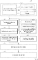
- La
figure 1 représente des étapes du procédé de fabrication de ciment selon un exemple de réalisation, où des étapes optionnelles du procédé sont indiquées en pointillé et des chemins en parallèles indiquent des variantes du procédé. - La
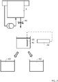
figure 2 représente un exemple de gravure d'un substrat à base de silicium, mettant en œuvre un équipement de régulation d'un bain de gravure. - La
figure 3 représente un exemple de mesure du rapport SiO2/K2O. - Les dessins sont donnés à titre d'exemples et ne sont pas limitatifs de l'invention. Ils constituent des représentations schématiques de principe destinées à faciliter la compréhension de l'invention et ne sont pas nécessairement à l'échelle des applications pratiques.
- Avant d'entamer une revue détaillée de modes de réalisation de l'invention, sont énoncées ci-après des caractéristiques optionnelles qui peuvent éventuellement être utilisées en association ou alternativement.
- Selon un exemple, le procédé comprend préalablement au mélange de la matière première aluminosilicate avec l'effluent de gravure, une vérification que le rapport molaire SiO2/M2O de l'au moins un effluent de gravure est supérieur ou égal à 0,8, et de préférence supérieur ou égal à 1,40.
- Selon un exemple, la vérification est effectuée avant ou après la fourniture de l'au moins un effluent de gravure.
- Selon un exemple, la vérification du rapport molaire SiO2/M2O comprend une mesure du rapport molaire SiO2/M2O dans l'au moins un effluent de gravure. La mesure du rapport molaire SiO2/M2O dans l'au moins un effluent de gravure peut être préalable à la fourniture de l'au moins un effluent de gravure.
- Selon un exemple, la vérification comprend, suite à la mesure du rapport molaire SiO2/M2O, une modification de l'au moins un effluent de gravure de sorte que le rapport molaire SiO2/M2O atteint une valeur déterminée. Ainsi, l'effluent peut être modifié de sorte que le rapport molaire SiO2/M2O est supérieur à 0,8, de préférence à 1,40, s'il ne l'était pas auparavant. De façon alternative ou complémentaire, l'effluent peut être modifié de sorte que le rapport molaire SiO2/M2O présente une valeur déterminée supérieure à 0,8, de préférence à 1,40. Ainsi, la répétabilité du procédé peut être améliorée. En outre, l'effluent peut être adapté selon les besoins d'un cimentier, en vue par exemple d'obtenir des propriétés particulières du ciment.
- Selon un exemple, la mesure du rapport molaire SiO2/M2O est réalisée dans un bain de gravure, lors d'un procédé de gravure du substrat à base de silicium, par un équipement de régulation du bain de gravure. La mesure de ce rapport peut ainsi être effectuée en directe lors du procédé de gravure, notamment de façon à identifier si le bain de gravure est apte à être fourni pour la fabrication du ciment.
- Selon un exemple, le procédé de gravure de silicium comprenant une pluralité de gravures successives de substrats à base de silicium dans le bain de gravure, plusieurs mesures du rapport molaire SiO2/M2O sont réalisées au cours de la pluralité de gravures successives. De préférence, une mesure est réalisée à intervalles réguliers au cours de la pluralité de gravures successives, et de préférence entre chaque gravure. La mesure de ce rapport peut ainsi être effectuée en directe le long du déroulement du procédé de gravure, notamment de façon à identifier lorsque le bain de gravure est apte à être fourni pour la fabrication du ciment.
- Selon un exemple, la modification de l'au moins un effluent de gravure comprend un ajustement des concentrations molaires relatives entre le silicate et le métal monovalent M.
- Selon un exemple, la modification de l'au moins un effluent de gravure comprend la combinaison d'une pluralité d'effluents de gravures distincts.
- Selon un exemple, le pH de l'au moins un effluent de gravure est supérieur à 9, et de préférence supérieur à 12. Ainsi, la quantité de silicate dissout dans l'effluent peut être maximisée.
- Selon un exemple, le rapport molaire SiO2/M2O est, de préférence, inférieur ou égal à 3. Ainsi, l'effluent de gravure présente un risque chimique moindre à la manipulation et au transport,
- Selon un exemple, la matière première aluminosilicate est choisie parmi des minéraux naturels comme la kaolinite ou des argiles, les laitiers de métallurgie, des cendres volantes, de la fumée de silice, des tufs volcaniques et des résidus miniers.
- Selon un exemple, la matière première aluminosilicate est issue un rejet d'un procédé industriel. La matière première aluminosilicate et l'effluent de gravure étant des déchets de procédés industriels valorisés dans ce procédé de fabrication de ciment, l'impact sur l'environnement du procédé est encore réduit.
- Selon un exemple, le substrat à base de silicium dont l'effluent de gravure est fourni, est un substrat en silicium cristallin et plus particulièrement en silicium monocristallin. Le substrat à base de silicium forme ou est destiné à former une cellule photovoltaïque par exemple une cellule photovoltaïque à base de silicium, par exemple de technologie de type homojonction ou hétérojonction ou un composant microélectronique.
- Il est précisé que dans le cadre de la présente invention, un paramètre « sensiblement égal/supérieur/inférieur à » une valeur donnée, que ce paramètre est égal/supérieur/inférieur à la valeur donnée, à plus ou moins 10 % près, voire à plus ou moins 5 % près, de cette valeur.
- On entend par composé ou matériau « à base » d'un matériau A, un composé ou matériau comprenant ce matériau A, et éventuellement d'autres matériaux.
- Un métal alcalin désigne de façon générale un élément métallique de la première colonne du tableau périodique des éléments chimiques, de préférence le potassium K ou le sodium Na.
- Le rapport molaire i/j entre deux composés i et j désigne le rapport de la quantité de matière en moles du composé i sur la quantité de matière en moles du composé j.
- Le procédé 1 de fabrication de ciment est maintenant décrit selon un exemple de réalisation en référence à la
figure 1 . - Pour fabriquer du ciment, le procédé 1 comprend la fourniture 10 d'un effluent de gravure de substrat 2 à base ou fait de silicium, et en particulier de silicium monocristallin. Cet effluent peut provenir de toute industrie et/ou tout procédé comprenant cette gravure. Par exemple, l'effluent peut provenir d'un procédé de fabrication de cellules photovoltaïques à base de silicium, ou d'un procédé microélectronique de traitement d'un substrat à base de silicium. Lorsque l'effluent provient d'un procédé de fabrication de cellules photovoltaïques, il est en particulier issu :
- d'une étape de gravure du substrat en silicium destinée à retirer les zones endommagées des substrats après découpe (étape également connue sous l'acronyme anglo-saxon SDE pour « Saw Dommage etching »), et/ou
- d'une étape de texturation de la surface du substrat destinée à créer les pyramides.
- Pour une usine de photovoltaïque de 1 GW/an de production de cellules photovoltaïques à base de silicium, on estime entre 3500 m3 et 5000 m3 le volume d'effluent de gravure généré, comprenant environ 200 tonnes de silicates alcalins dissouts. Ces effluents constituent des déchets chimiques, valorisables par leur réinjection dans le procédé 1 pour la fabrication de ciment. Ainsi le coût énergétique et les ressources pour fabriquer ce ciment sont diminués. Un ciment dont la fabrication présente un impact environnemental réduit peut être obtenu.
- Lors d'une gravure d'un substrat à base de silicium, décrit en détail ultérieurement, le substrat 2 est exposé à des réactifs d'un bain de gravure 4, choisis pour réagir avec le silicium et ainsi mettre en forme la surface du substrat. Lors d'un procédé 14 de gravure, le silicium est typiquement oxydé en silice, de formule chimique SiO2 puis gravé 140. Le bain de gravure 4 se charge en silice dissoute pour former l'effluent de gravure. Typiquement, le bain de gravure se charge en silice dissoute au fur et à mesure de la gravure 140 d'une pluralité de substrats 2, comme il sera vu dans la suite.
- À l'issue de la gravure 140 de ces substrats 2, l'effluent comprend au moins un type, et par exemple plusieurs types de silicates de métal alcalin M dissous en solution. Selon un exemple, la solution est au moins en partie aqueuse, et de préférence la solution est une solution aqueuse d'au moins un silicate de métal alcalin M dissous. Le silicate de métal alcalin non dissous présente la formule chimique SiO2 : M2O. Le métal alcalin peut varier selon les réactifs utilisés dans le bain de gravure. Le métal alcalin M est de préférence le potassium (K) ou le sodium (Na). Le silicate de métal alcalin est donc de préférence un silicate de potassium, ou un silicate de sodium.
- Dans le bain de gravure 4, et donc dans l'effluent subséquent, l'oxyde de métal alcalin M2O peut être dissout en hydroxyde de métal alcalin, de formule MOH, selon la réaction chimique suivante : M2O + H2O → 2 M+ + 2 OH-. La silice peut être dissoute selon la réaction chimique suivante : SiO2 (s) + 2 H2O → Si(OH)4 (aq). En fonction du pH de l'effluent, Si(OH)4 est converti dans l'un ou l'autre des espèces des couples acides/bases conjugués H3SiO4 - et H2SiO4 2- . Généralement, on désigne par silice dissoute, ou encore « silice totale », l'ensemble des espèces comprenant l'élément silicium, issues de son oxydation en silice et sa dissolution dans le bain de gravure. La mesure des espèces dissoutes en solution permet de retrouver par équivalence les quantités relatives de SiO2 et M2O dissous et donc le rapport molaire SiO2/M2O en solution.
- L'effluent de gravure peut être mélangé 13 à une matière première aluminosilicate fournie 12. Lors de ce mélange 13, le silicate de métal alcalin réagit avec la matière première aluminosilicate pour former le ciment géopolymère. Pour cela, l'effluent de gravure présente un rapport molaire SiO2/M2O supérieur ou égal à 0,8 et de préférence supérieur ou égal à 1,40. Ces valeurs minimums du rapport molaire permettent d'assurer l'obtention d'un ciment présentant des propriétés mécaniques satisfaisantes Plus préférentiellement encore, le rapport molaire SiO2/M2O peut être supérieur ou égal à 1,45. Lorsque le rapport molaire SiO2/M2O est supérieur ou égal à 1,45, .Le transport et la manipulation de l'effluent sont ainsi facilités. Afin de s'assurer de cette valeur, et donc de la qualité et/ou de la répétabilité du ciment obtenu, le procédé 1 peut comprendre une vérification 11 du rapport molaire SiO2/M2O. Cette vérification 11 peut notamment être faire pour vérifier que ce rapport molaire SiO2/M2O est supérieur ou égal aux valeurs précitées. Cette vérification 11 peut être effectuée préalablement au mélange 13, et/ou préalablement à la fourniture 10 de l'effluent de gravure.
- La valeur du rapport molaire SiO2/M2O peut être adaptée 111 selon la nature de la matière première aluminosilicate. Le rapport molaire SiO2/M2O peut être de préférence inférieur à 4, de préférence à 3. Ainsi, l'effluent est considéré comme chimiquement peu dangereux pour un opérateur. Le transport de l'effluent et sa manipulation dans le procédé 1 sont ainsi facilités. En outre, l'effluent est alors plus stable, ce qui facilite la conservation de l'effluent.
- Selon le pH de l'effluent de gravure, la quantité de silice pouvant être dissoute dans l'effluent peut être optimisée. Selon un exemple, le pH de l'effluent de gravure est supérieur ou égal à 9. Ainsi, la concentration molaire en silice peut atteindre au moins 10-3 mol/L. De préférence, le pH de l'effluent de gravure est supérieur ou égal à 12. Ainsi, la concentration molaire en silice peut atteindre au moins 0,5 mol/L. Par exemple, pour un effluent de gravure comprenant de l'hydroxyde de potassium dilué à une fraction massique de sensiblement de 3,5 % par rapport au poids total de la solution, le pH est sensiblement égal à 13,8 et le bain de gravure peut comprendre sensiblement plusieurs dizaines de mol/L de silice dissoute. Selon un exemple, la teneur en silice dissoute dans l'effluent est comprise entre 2 et 10 mol/L. Le procédé 1 peut comprendre une mesure 110' du pH de l'effluent de gravure, et un ajustement 111 du pH de l'effluent pour atteindre une valeur de pH déterminée. La mesure 110' et/ou l'ajustement 111 peuvent être réalisé peut être effectuée préalablement au mélange 13, et/ou préalablement à la fourniture 10 de l'effluent de gravure. Lors de l'ajustement 111, l'effluent de gravure peut être tamponné pour éviter des variations de pH pouvant entrainer une modification des équilibres de dissolution, et notamment une précipitation de la silice dissoute.
- Au moins une matière première aluminosilicate peut être fournie 12 pour fabriquer le ciment. Plusieurs matières premières aluminosilicates peuvent être fournies 12 et mélangées 13 à l'effluent, par exemple pour moduler les propriétés du ciment obtenu. La matière première aluminosilicate comprend des silicates dans lesquels des atomes de silicium sont remplacés par des atomes d'aluminium. La matière première aluminosilicate peut être choisie parmi des minéraux naturels comme la kaolinite ou des argiles, ou encore de tufs volcaniques. La matière première aluminosilicate peut être issue d'un procédé industriel. Ainsi, la matière première aluminosilicate et l'effluent de gravure peuvent être tous deux issus de procédés industriels, dont les déchets sont donc valorisés par la fabrication de ciment selon le procédé 1. Concernant la matière première aluminosilicate, il n'y a dès lors pas de coût d'extraction supplémentaire. L'énergie et les ressources nécessaires à la fabrication de ciment, ainsi que les rejets en CO2, sont encore limités. L'impact sur l'environnement du procédé 1 est encore réduit.
- Par exemple, la matière première aluminosilicate peut être issue de scories de métallurgie, tels que les laitiers de métallurgie, et plus particulièrement les laitiers de hauts fourneaux. Selon un exemple, la matière première aluminosilicate est un laitier granulé et broyé de haut fourneau. La matière première aluminosilicate peut être des cendres volantes, généralement issues de la combustion de l'anthracite ou de charbon bitumineux, ou encore de lignite ou de charbon sub-bitumineux. La matière première aluminosilicate peut être de la fumée de silice, généralement produite de la production de silicium par réduction du quartz ou de la production d'alliages de ferrosilicium. La matière première aluminosilicate peut être issue de résidus miniers.
- Lors du mélange 13 de la matière première aluminosilicate avec l'effluent de gravure, la matière première aluminosilicate et l'effluent de gravure peuvent être mélangés dans des proportions variables, notamment selon la nature de la matière première aluminosilicate et les propriétés recherchées du ciment. Selon un exemple, la matière première aluminosilicate peut représenter au moins 70 % du mélange 13. L'effluent de gravure, éventuellement complété par de l'eau, peut représenter le reste du mélange. Selon un exemple dans lequel la matière première aluminosilicate est un laitier granulé et broyé de haut fourneau, le mélange 13 peut comprendre de 80 à 90% de laitier pour 10 à 20% d'effluent de gravure.
- Afin de vérifier 11 le rapport molaire SiO2/M2O de l'effluent de gravure, le procédé peut comprendre une mesure 110 de ce rapport. La mesure 110 peut comprendre une mesure de la quantité de silice dissoute dans l'effluent, et de la quantité équivalente de M2O à partir de la quantité l'hydroxyde de métal alcalin M dissous dans l'effluent. Cette mesure peut être effectuée préalablement au mélange 13, et/ou préalablement à la fourniture 10 de l'effluent de gravure. Cette mesure peut être effectuée sur un prélèvement dans l'effluent de gravure, ou directement dans le bain de gravure comme il sera vu dans la suite. Ces mesures peuvent être effectuées par tout moyen connus de l'homme du métier. Par exemple, la quantité de silice dissoute peut être mesurée par un dosage de la silice totale. Des techniques optiques d'analyse de spectres peuvent en outre être envisagées.
- Afin d'adapter la valeur du rapport molaire SiO2/M2O à une valeur particulière, la procédé 1 peut comprendre une modification 111 de l'effluent de gravure. Cette modification 111 peut comprendre un ajustement des concentrations relatives en SiO2 et K2O, par exemple par dilution, par concentration et/ou ajout d'une ou plusieurs espèces chimiques dans l'effluent. L'ajustement est de préférence fait en fonction de la mesure 110 effectuée. De façon alternative ou complémentaire, la modification 111 de l'effluent de gravure peut comprendre une combinaison d'une pluralité d'effluents, de préférence dont le rapport molaire SiO2/M2O a été mesuré 110 au préalable. La gestion des déchets de bain de gravure est ainsi optimisée selon la composition chimique des effluents, pour obtenir une valeur de rapport molaire SiO2/M2O particulière. Le coût et l'impact environnemental du procédé sont ainsi encore minimisés.
- L'industriel de la gravure du silicium peut vérifier 11 le rapport molaire SiO2/M2O et peut modifier 111 l'effluent de gravure selon les besoins d'un cimentier mettant en œuvre le procédé 1. Le ou les effluents de gravures peuvent être fournis au cimentier. Selon un exemple, le cimentier réalise, après réception, la vérification 11 du rapport molaire SiO2/M2O. Le cimentier peut alors modifier 111 l'effluent de gravure selon les besoins spécifiques à la fabrication d'un ciment. Ces effluents peuvent être fournis de l'industriel de la gravure de silicium à un tiers. Le tiers peut ensuite fournir 10 le ou les effluent(s) au cimentier. Avant la fourniture 10 de l'effluent au cimentier, le tiers peut effectuer la vérification 11, et peut modifier 111 l'effluent. L'un ou plusieurs des trois acteurs peut assurer la vérification 11 et peut modifier 111 l'effluent de gravure.
- Selon un exemple, une mesure 141 du rapport molaire SiO2/M2O peut être effectuée par un industriel de la gravure de silicium. Typiquement, lors d'un procédé de gravure de silicium 14, le substrat 2 à base de silicium est gravé en bain de gravure 4. Ce procédé est maintenant décrit en référence à la
figure 2 . Lors du procédé de gravure 14, la surface endommagées, communément désignée zone écrouie, issue de la découpe des plaques de silicium, est retirée. Cette gravure 140 de la surface des plaques de silicium est communément abrégée SDR, de l'anglais saw damaged removal, que l'on peut traduire par retrait de la zone écrouie, ou SDE, de l'anglais saw damaged etching, que l'on peut traduire par gravure de la zone écrouie. Cette gravure 140 s'effectue généralement dans un bain d'une solution basique d'hydroxyde de potassium, de formule KOH, ou d'hydroxyde de sodium, de formule NaOH. - Après le retrait de la zone écrouie, le procédé 14 peut comprendre une deuxième étape de gravure 140 dans un bain d'une solution basique d'hydroxyde de potassium ou d'hydroxyde de sodium, généralement appelée texturation. La texturation est configurée pour former des pyramides en surface du substrat par le principe de gravure anisotropique, selon l'orientation des plans cristallins du silicium. À titre indicatif, l'étape de SDR représente environ les deux tiers de la masse de silicium retirée sur les substrats et la durée de vie d'un bain de gravure est souvent donnée pour le traitement d'environ 60 000 substrats. L'étape de texturation représente environ un tiers de la masse de silicium retirée sur les substrats et la durée de vie du bain de gravure est d'environ 20 000 à 30 000 substrats.
- Lors d'un procédé 14 de gravure du silicium, chaque bain de gravure voit en effet passer une succession de lots de substrats 2. Avec chaque passage de lot, une stratégie de bain est associée afin de compléter le bain de gravure. Plus particulièrement, de l'hydroxyde de potassium ou de sodium et de l'eau déionisée et/ou déminéralisée sont ajoutés entre le passage de chaque lot. Un ajustement du volume du bain est effectué afin de compenser d'une part la part de liquide perdue par transport des substrats 2, le renouvellement suffisant des espèces chimiques responsables de la gravure et la compensation en volume du bain pour conserver un volume et une composition chimique suffisante pour la gravure 140 du substrat 2.
- Typiquement, comme illustré par la
figure 2 , une partie du bain de gravure 4 peut être retiré par un drain 40. Des moyens d'ajouts 30 d'eau et/ou de réactifs peuvent ensuite être actionnés pour compléter le bain de gravure 4. Au fur et à mesure des gravures, le bain de gravure 4 s'enrichit en silice dissoute. Le rapport molaire SiO2/M2O peut donc évoluer jusqu'à ce que le bain de gravure 4, et l'effluent de gravure résultant, soit à apte à être utilisé dans le procédé de fabrication de ciment. - À titre d'exemple, plusieurs stratégies de bain et leur impact sur le rapport SiO2/M2O sont décrits. Ces stratégies correspondent à un équipement industriel dont le volume de bain est de 131 L afin de traiter 200 wafers de silicium par lot. Selon une première stratégie, on peut ajouter 0,5 L d'une solution de KOH à 45 % en fraction massique, par rapport au poids total de la solution de KOH, et 2 L d'eau entre chaque lot. Après le traitement du 40ème lot, un rapport molaire de SiO2/K2O supérieur à 1,4 peut être obtenu. L'effluent de gravure final, après passage de l'ensemble des lots, peut ainsi présenter un rapport molaire de SiO2/K2O sensiblement égal à 1,7.
- Selon une deuxième stratégie, on peut ajouter 0,3 L d'une solution de KOH à 45 % en fraction massique, par rapport au poids total de la solution de KOH, et 2,5 L d'eau entre chaque lot. Après le traitement du 40ème lot, un rapport molaire de SiO2/K2O supérieur à 2 peut être obtenu. L'effluent de gravure final, après passage de l'ensemble des lots, peut ainsi présenter un rapport molaire de SiO2/K2O sensiblement égal à 2,7.
- Selon une troisième stratégie, on peut ajouter 0,3 L d'une solution de KOH à 45 % en fraction massique, par rapport au poids total de la solution de KOH, et 1 L d'eau entre chaque lot. Après le traitement du 40ème lot, un rapport molaire de SiO2/K2O supérieur à 2 peut être obtenu. L'effluent de gravure final, après passage de l'ensemble des lots, peut ainsi présenter un rapport molaire de SiO2/K2O sensiblement égal à 2,5.
- Selon une quatrième stratégie, on peut ajouter 1 L d'une solution de KOH à 45 % en fraction massique, par rapport au poids total de la solution de KOH, et 3 L d'eau entre chaque lot. Après le traitement du 25ème lot, un rapport molaire de SiO2/K2O supérieur à 0,7 peut être obtenu. L'effluent de gravure final, après passage de l'ensemble des lots, peut ainsi présenter un rapport molaire de SiO2/K2O sensiblement égal à 0,9.
- Selon un exemple, le procédé de gravure de silicium 140, et notamment la stratégie de bain, peuvent être adaptés pour obtenir un rapport molaire SiO2/M2O particulier.
- L'industriel de la gravure du silicium peut mettre en œuvre la vérification 11 du rapport SiO2/M2O dans le bain de gravure et/ou dans l'effluent en résultant. Selon un exemple, la mesure 141 du rapport SiO2/M2O peut être réalisée par mesure ou prélèvement dans le bain de gravure 4. La mesure 141 peut être effectuée à intervalles réguliers lors du procédé de gravure 140, par exemple après qu'un nombre déterminé de lots de substrats aient été traités. Selon l'exemple illustré en
figure 2 , le procédé de gravure 140 peut mettre en œuvre un équipement de régulation 3 du bain de gravure 4. Cet équipement comprend les moyens d'ajouts 30 de réactifs et/ou d'eau dans le bain de gravure 4, actionné par un ou plusieurs régulateur(s) 31. L'équipement de régulation 3 peut comprendre un capteur 33, pouvant être relié à une centrale de traitement 34 de la valeur mesurée. Le capteur 33 peut être disposé dans le bain de gravure 4. De préférence, et comme illustré enfigure 2 , le capteur 33 est disposé sur une boucle de recirculation du bain de gravure 4, permettant une mesure en ligne sur une fraction du bain de gravure 4. - De façon alternative ou complémentaire, la mesure 141 du rapport SiO2/M2O peut être réalisée par mesure ou prélèvement dans un effluent issu d'un bain de gravure 4 au niveau d'une boucle de recirculation du bain de gravure 4, et/ou après drainage comme l'illustre la
figure 3 . La mesure 141 peut par exemple être effectuée grâce à un capteur 33, pouvant être relié à une centrale de traitement 34 de la valeur mesurée. Suite à la mesure 141, différents effluents de gravure peuvent être répartis selon leur rapport molaire SiO2/M2O. Les effluents de gravure peuvent être séparés dans différentes cuves 42, 43, éventuellement pour une modification 111 subséquente. - Le procédé 1 peut comprendre en outre, lors de ou suite au mélange 13 de la matière première aluminosilicate et de l'effluent de gravure, un mélange de ces éléments avec un ciment distinct, par exemple un ciment Portland. Le ciment ou le mélange de ciments obtenus à l'issu du procédé 1 peut être utilisé pour la fabrication d'un béton, par notamment un mélange avec des granulats.
- Au vu de la description qui précède, il apparaît clairement que l'invention propose une solution particulièrement avantageuse de valorisation d'effluent de gravure et un procédé permettant de réduire l'impact environnemental d'un procédé de fabrication de ciment à partir de matière première aluminosilicate
- L'invention n'est pas limitée aux modes de réalisations précédemment décrits et s'étend à tous les modes de réalisation couverts par les revendications.
Claims (14)
- Procédé (1) de fabrication de ciment comprenant :- une fourniture (10) d'au moins un effluent de gravure d'un substrat (2) à base de silicium comprenant un silicate d'un métal alcalin M dissout, de formule SiO2 : M2O, présentant un rapport molaire SiO2/M2O supérieur ou égal à 0,8, et de préférence supérieur ou égal à 1,40,- une fourniture (12) d'une matière première aluminosilicate, et- un mélange (13) de la matière première aluminosilicate avec l'effluent de gravure.
- Procédé selon la revendication précédente, comprenant préalablement au mélange (13) de la matière première aluminosilicate avec l'effluent de gravure, une vérification (11), que le rapport molaire SiO2/M2O de l'au moins un effluent de gravure est supérieur ou égal à 0,8, et de préférence supérieur ou égal à 1,40.
- Procédé (1) selon la revendication précédente, dans lequel la vérification (11) du rapport molaire SiO2/M2O comprend une mesure (110) du rapport molaire SiO2/M2O dans l'au moins un effluent de gravure, et optionnellement une modification (111) de l'au moins un effluent de gravure de sorte que le rapport molaire SiO2/M2O atteint une valeur déterminée.
- Procédé (1) selon l'une quelconque des revendications précédentes, dans lequel le procédé (1) comprend, préalablement à la fourniture (10) de l'au moins un effluent de gravure, la mesure (141, 110) du rapport molaire SiO2/M2O dans l'au moins un effluent de gravure, et optionnellement une modification (111) de l'au moins un effluent de gravure de sorte que le rapport molaire SiO2/M2O atteint une valeur déterminée.
- Procédé (1) selon la revendication précédente, dans lequel la mesure (141) du rapport molaire SiO2/M2O est réalisée dans un bain de gravure (4), lors d'un procédé de gravure (14) du substrat (2) à base de silicium, par un équipement de régulation (3) du bain de gravure (4).
- Procédé (1) selon la revendication précédente, dans lequel, le procédé de gravure (14) de silicium comprenant une pluralité de gravures (140) successives de substrats (2) à base de silicium dans le bain de gravure (4), plusieurs mesures (141) du rapport molaire SiO2/M2O étant réalisées au cours de la pluralité de gravures (140) successives.
- Procédé (1) selon l'une quelconque des quatre revendications précédentes, dans lequel la modification (111) de l'au moins un effluent de gravure comprend un ajustement des concentrations molaires relatives entre le silicate et le métal monovalent M, et/ou la combinaison d'une pluralité d'effluents de gravures distincts.
- Procédé (1) selon l'une quelconque des revendications précédentes, dans lequel le pH de l'au moins un effluent de gravure est supérieur à 9.
- Procédé (1) selon l'une quelconque des revendications précédentes, dans lequel le rapport molaire SiO2/M2O est inférieur ou égal à 3.
- Procédé (1) selon l'une quelconque des revendications précédentes, dans lequel la matière première aluminosilicate est choisie parmi des minéraux naturels comme la kaolinite ou des argiles, les laitiers de métallurgie, des cendres volantes, de la fumée de silice, des tufs volcaniques et des résidus miniers.
- Procédé (1) selon l'une quelconque des revendications précédentes, dans lequel le substrat (2) à base de silicium dont l'effluent de gravure est fourni, est un substrat (2) à base de silicium formant ou destiné à former une cellule photovoltaïque.
- Procédé (1) selon l'une quelconque des revendications 1 à 10, dans lequel le substrat (2) à base de silicium dont l'effluent de gravure est fourni, est un substrat (2) à base de silicium formant ou destiné à former un composant microélectronique.
- Utilisation d'un effluent de gravure d'un substrat (2) à base de silicium, formé d'une solution de silicate d'un métal monovalent, de formule SiO2: M2O, et présentant un rapport molaire SiO2/M2O supérieur ou égal à 0,8, et de préférence supérieur ou égal à 1,40, en mélange avec une matière première aluminosilicate, pour la fabrication de ciment.
- Utilisation selon la revendication précédente, dans laquelle le substrat (2) à base de silicium dont l'effluent de gravure est fourni, est un substrat (2) à base de silicium formant ou destiné à former une cellule photovoltaïque ou un composant microélectronique.
Applications Claiming Priority (1)
| Application Number | Priority Date | Filing Date | Title |
|---|---|---|---|
| FR2012164A FR3116529B1 (fr) | 2020-11-26 | 2020-11-26 | Procédé de fabrication de ciment à partir d’une matière première aluminosilicate |
Publications (2)
| Publication Number | Publication Date |
|---|---|
| EP4005994A1 true EP4005994A1 (fr) | 2022-06-01 |
| EP4005994B1 EP4005994B1 (fr) | 2024-01-03 |
Family
ID=74183425
Family Applications (1)
| Application Number | Title | Priority Date | Filing Date |
|---|---|---|---|
| EP21209403.1A Active EP4005994B1 (fr) | 2020-11-26 | 2021-11-19 | Procédé de fabrication de ciment à partir d'une matière première aluminosilicate |
Country Status (4)
| Country | Link |
|---|---|
| US (1) | US11919808B2 (fr) |
| EP (1) | EP4005994B1 (fr) |
| CN (1) | CN114538805A (fr) |
| FR (1) | FR3116529B1 (fr) |
Citations (1)
| Publication number | Priority date | Publication date | Assignee | Title |
|---|---|---|---|---|
| JP2020186143A (ja) * | 2019-05-10 | 2020-11-19 | 公立大学法人北九州市立大学 | ジオポリマー組成物の製造方法 |
Family Cites Families (4)
| Publication number | Priority date | Publication date | Assignee | Title |
|---|---|---|---|---|
| CN103570167A (zh) * | 2012-08-03 | 2014-02-12 | 库特勒自动化系统(苏州)有限公司 | 硅晶片碱腐蚀废液的回收处理方法及系统 |
| CN105621907A (zh) * | 2016-01-18 | 2016-06-01 | 桂林电子科技大学 | 一种钙基地聚合物及其制备方法 |
| CN108751821B (zh) * | 2018-07-27 | 2020-10-09 | 成都宏基建材股份有限公司 | 一种地质聚合物混凝土及其制备方法 |
| CN108975780A (zh) * | 2018-07-27 | 2018-12-11 | 成都宏基建材股份有限公司 | 一种地质聚合物修补砂浆及其制备和使用方法 |
-
2020
- 2020-11-26 FR FR2012164A patent/FR3116529B1/fr active Active
-
2021
- 2021-11-19 EP EP21209403.1A patent/EP4005994B1/fr active Active
- 2021-11-23 US US17/456,249 patent/US11919808B2/en active Active
- 2021-11-25 CN CN202111411566.XA patent/CN114538805A/zh active Pending
Patent Citations (1)
| Publication number | Priority date | Publication date | Assignee | Title |
|---|---|---|---|---|
| JP2020186143A (ja) * | 2019-05-10 | 2020-11-19 | 公立大学法人北九州市立大学 | ジオポリマー組成物の製造方法 |
Non-Patent Citations (2)
| Title |
|---|
| J. DAVIDOVITZ, TECHNIQUES DE L'INGÉNIEUR, 10 October 2014 (2014-10-10) |
| OGUNDIRAN M B ET AL: "Geopolymerisation of fly ashes with waste aluminium anodising etching solutions", JOURNAL OF ENVIRONMENTAL MANAGEMENT, ELSEVIER, AMSTERDAM, NL, vol. 181, 20 June 2016 (2016-06-20), pages 118 - 123, XP029709734, ISSN: 0301-4797, DOI: 10.1016/J.JENVMAN.2016.06.017 * |
Also Published As
| Publication number | Publication date |
|---|---|
| FR3116529A1 (fr) | 2022-05-27 |
| FR3116529B1 (fr) | 2022-11-04 |
| US11919808B2 (en) | 2024-03-05 |
| EP4005994B1 (fr) | 2024-01-03 |
| US20220162120A1 (en) | 2022-05-26 |
| CN114538805A (zh) | 2022-05-27 |
Similar Documents
| Publication | Publication Date | Title |
|---|---|---|
| EP3707111B1 (fr) | Liant ettringitique pour la fabrication de matériaux de construction et procédé de sa préparation | |
| EP1678725B1 (fr) | Utilisation de carbonates mixtes frittes pour le confinement de carbone radioactif | |
| EP0130854B1 (fr) | Procédé de solidification de déchets liquides de forte acidité ou alcalinité | |
| CN101623898B (zh) | 一种线切割工艺中砂浆的化学回收方法 | |
| CA2911855C (fr) | Liant de geosynthese comprenant un activateur alcalino-calcique et un compose silico-alumineux | |
| EP3475221B1 (fr) | Procede de production de sulfate de calcium | |
| FR2669327A1 (fr) | Procede pour augmenter la surface specifique et les proprietes plastiques de la chaux hydratee. | |
| EP0406550A1 (fr) | Procédé de préparation par voie aqueuse de dihydrate de sulfate de calcium purifié | |
| EP4005994B1 (fr) | Procédé de fabrication de ciment à partir d'une matière première aluminosilicate | |
| KR102027999B1 (ko) | 친환경성 및 고액 분리 성능이 개선된 암모늄계 불소화합물 함유 폐액의 처리방법 | |
| WO1991014655A1 (fr) | Procede de traitement d'une solution aqueuse contenant principalement de l'acide nitrique et de l'acide fluorhydrique | |
| CN106190073A (zh) | 一种低渗复杂结垢储层多功能清防垢剂配方及制备方法 | |
| WO2023281220A1 (fr) | Composition cimentaire comprenant du biochar carbonaté | |
| EP3873683B1 (fr) | Procédé de conditionnement par cimentation d'un déchet acide | |
| CA3183456C (fr) | Procede de fabrication d'un beton formule a base de laitier active | |
| JPH11228134A (ja) | 二水石膏の製造方法 | |
| EP0195723B1 (fr) | Procédé et dispositif pour le conditionnement, par liants hydrauliques, d'effluents radioactifs de faible et moyenne activité | |
| TWI741683B (zh) | 以矽泥廢料製造高模數水玻璃之方法 | |
| FR3053257A1 (fr) | Procede d'immobilisation d'un dechet comprenant du mercure | |
| EP0134732B1 (fr) | Procédé de fabrication d'acide phosphorique purifié, appareillage et produit obtenu | |
| EP2742012A1 (fr) | Procédé de sélection de laitiers d'aciérie de conversion | |
| EP4347526A1 (fr) | Amélioration du maintien d'ouvrabilité de compositions hydrauliques à faible teneur en clinker | |
| FR3163069A1 (fr) | Procédé de formation de minéraux négatifs en carbone utilisant des macroorganismes biominéralisants | |
| CA3028833C (fr) | Procede de production de sulfate de calcium | |
| WO2006087484A2 (fr) | Fabrication d'un materiau solide a partir d'un hydroxyde alcalin |
Legal Events
| Date | Code | Title | Description |
|---|---|---|---|
| PUAI | Public reference made under article 153(3) epc to a published international application that has entered the european phase |
Free format text: ORIGINAL CODE: 0009012 |
|
| STAA | Information on the status of an ep patent application or granted ep patent |
Free format text: STATUS: REQUEST FOR EXAMINATION WAS MADE |
|
| 17P | Request for examination filed |
Effective date: 20211119 |
|
| AK | Designated contracting states |
Kind code of ref document: A1 Designated state(s): AL AT BE BG CH CY CZ DE DK EE ES FI FR GB GR HR HU IE IS IT LI LT LU LV MC MK MT NL NO PL PT RO RS SE SI SK SM TR |
|
| GRAP | Despatch of communication of intention to grant a patent |
Free format text: ORIGINAL CODE: EPIDOSNIGR1 |
|
| STAA | Information on the status of an ep patent application or granted ep patent |
Free format text: STATUS: GRANT OF PATENT IS INTENDED |
|
| INTG | Intention to grant announced |
Effective date: 20230301 |
|
| GRAJ | Information related to disapproval of communication of intention to grant by the applicant or resumption of examination proceedings by the epo deleted |
Free format text: ORIGINAL CODE: EPIDOSDIGR1 |
|
| STAA | Information on the status of an ep patent application or granted ep patent |
Free format text: STATUS: REQUEST FOR EXAMINATION WAS MADE |
|
| GRAP | Despatch of communication of intention to grant a patent |
Free format text: ORIGINAL CODE: EPIDOSNIGR1 |
|
| INTC | Intention to grant announced (deleted) | ||
| STAA | Information on the status of an ep patent application or granted ep patent |
Free format text: STATUS: GRANT OF PATENT IS INTENDED |
|
| INTG | Intention to grant announced |
Effective date: 20230810 |
|
| GRAS | Grant fee paid |
Free format text: ORIGINAL CODE: EPIDOSNIGR3 |
|
| GRAA | (expected) grant |
Free format text: ORIGINAL CODE: 0009210 |
|
| STAA | Information on the status of an ep patent application or granted ep patent |
Free format text: STATUS: THE PATENT HAS BEEN GRANTED |
|
| AK | Designated contracting states |
Kind code of ref document: B1 Designated state(s): AL AT BE BG CH CY CZ DE DK EE ES FI FR GB GR HR HU IE IS IT LI LT LU LV MC MK MT NL NO PL PT RO RS SE SI SK SM TR |
|
| REG | Reference to a national code |
Ref country code: GB Ref legal event code: FG4D Free format text: NOT ENGLISH |
|
| REG | Reference to a national code |
Ref country code: CH Ref legal event code: EP |
|
| REG | Reference to a national code |
Ref country code: DE Ref legal event code: R096 Ref document number: 602021008310 Country of ref document: DE |
|
| REG | Reference to a national code |
Ref country code: IE Ref legal event code: FG4D Free format text: LANGUAGE OF EP DOCUMENT: FRENCH |
|
| REG | Reference to a national code |
Ref country code: LT Ref legal event code: MG9D |
|
| PG25 | Lapsed in a contracting state [announced via postgrant information from national office to epo] |
Ref country code: ES Free format text: LAPSE BECAUSE OF FAILURE TO SUBMIT A TRANSLATION OF THE DESCRIPTION OR TO PAY THE FEE WITHIN THE PRESCRIBED TIME-LIMIT Effective date: 20240103 |
|
| PG25 | Lapsed in a contracting state [announced via postgrant information from national office to epo] |
Ref country code: ES Free format text: LAPSE BECAUSE OF FAILURE TO SUBMIT A TRANSLATION OF THE DESCRIPTION OR TO PAY THE FEE WITHIN THE PRESCRIBED TIME-LIMIT Effective date: 20240103 |
|
| REG | Reference to a national code |
Ref country code: NL Ref legal event code: MP Effective date: 20240103 |
|
| REG | Reference to a national code |
Ref country code: AT Ref legal event code: MK05 Ref document number: 1646654 Country of ref document: AT Kind code of ref document: T Effective date: 20240103 |
|
| PG25 | Lapsed in a contracting state [announced via postgrant information from national office to epo] |
Ref country code: NL Free format text: LAPSE BECAUSE OF FAILURE TO SUBMIT A TRANSLATION OF THE DESCRIPTION OR TO PAY THE FEE WITHIN THE PRESCRIBED TIME-LIMIT Effective date: 20240103 |
|
| PG25 | Lapsed in a contracting state [announced via postgrant information from national office to epo] |
Ref country code: NL Free format text: LAPSE BECAUSE OF FAILURE TO SUBMIT A TRANSLATION OF THE DESCRIPTION OR TO PAY THE FEE WITHIN THE PRESCRIBED TIME-LIMIT Effective date: 20240103 |
|
| PG25 | Lapsed in a contracting state [announced via postgrant information from national office to epo] |
Ref country code: IS Free format text: LAPSE BECAUSE OF FAILURE TO SUBMIT A TRANSLATION OF THE DESCRIPTION OR TO PAY THE FEE WITHIN THE PRESCRIBED TIME-LIMIT Effective date: 20240503 |
|
| PG25 | Lapsed in a contracting state [announced via postgrant information from national office to epo] |
Ref country code: LT Free format text: LAPSE BECAUSE OF FAILURE TO SUBMIT A TRANSLATION OF THE DESCRIPTION OR TO PAY THE FEE WITHIN THE PRESCRIBED TIME-LIMIT Effective date: 20240103 |
|
| PG25 | Lapsed in a contracting state [announced via postgrant information from national office to epo] |
Ref country code: GR Free format text: LAPSE BECAUSE OF FAILURE TO SUBMIT A TRANSLATION OF THE DESCRIPTION OR TO PAY THE FEE WITHIN THE PRESCRIBED TIME-LIMIT Effective date: 20240404 |
|
| PG25 | Lapsed in a contracting state [announced via postgrant information from national office to epo] |
Ref country code: HR Free format text: LAPSE BECAUSE OF FAILURE TO SUBMIT A TRANSLATION OF THE DESCRIPTION OR TO PAY THE FEE WITHIN THE PRESCRIBED TIME-LIMIT Effective date: 20240103 Ref country code: RS Free format text: LAPSE BECAUSE OF FAILURE TO SUBMIT A TRANSLATION OF THE DESCRIPTION OR TO PAY THE FEE WITHIN THE PRESCRIBED TIME-LIMIT Effective date: 20240403 |
|
| PG25 | Lapsed in a contracting state [announced via postgrant information from national office to epo] |
Ref country code: AT Free format text: LAPSE BECAUSE OF FAILURE TO SUBMIT A TRANSLATION OF THE DESCRIPTION OR TO PAY THE FEE WITHIN THE PRESCRIBED TIME-LIMIT Effective date: 20240103 Ref country code: CZ Free format text: LAPSE BECAUSE OF FAILURE TO SUBMIT A TRANSLATION OF THE DESCRIPTION OR TO PAY THE FEE WITHIN THE PRESCRIBED TIME-LIMIT Effective date: 20240103 |
|
| PG25 | Lapsed in a contracting state [announced via postgrant information from national office to epo] |
Ref country code: RS Free format text: LAPSE BECAUSE OF FAILURE TO SUBMIT A TRANSLATION OF THE DESCRIPTION OR TO PAY THE FEE WITHIN THE PRESCRIBED TIME-LIMIT Effective date: 20240403 Ref country code: NO Free format text: LAPSE BECAUSE OF FAILURE TO SUBMIT A TRANSLATION OF THE DESCRIPTION OR TO PAY THE FEE WITHIN THE PRESCRIBED TIME-LIMIT Effective date: 20240403 Ref country code: LT Free format text: LAPSE BECAUSE OF FAILURE TO SUBMIT A TRANSLATION OF THE DESCRIPTION OR TO PAY THE FEE WITHIN THE PRESCRIBED TIME-LIMIT Effective date: 20240103 Ref country code: IS Free format text: LAPSE BECAUSE OF FAILURE TO SUBMIT A TRANSLATION OF THE DESCRIPTION OR TO PAY THE FEE WITHIN THE PRESCRIBED TIME-LIMIT Effective date: 20240503 Ref country code: HR Free format text: LAPSE BECAUSE OF FAILURE TO SUBMIT A TRANSLATION OF THE DESCRIPTION OR TO PAY THE FEE WITHIN THE PRESCRIBED TIME-LIMIT Effective date: 20240103 Ref country code: GR Free format text: LAPSE BECAUSE OF FAILURE TO SUBMIT A TRANSLATION OF THE DESCRIPTION OR TO PAY THE FEE WITHIN THE PRESCRIBED TIME-LIMIT Effective date: 20240404 Ref country code: CZ Free format text: LAPSE BECAUSE OF FAILURE TO SUBMIT A TRANSLATION OF THE DESCRIPTION OR TO PAY THE FEE WITHIN THE PRESCRIBED TIME-LIMIT Effective date: 20240103 Ref country code: BG Free format text: LAPSE BECAUSE OF FAILURE TO SUBMIT A TRANSLATION OF THE DESCRIPTION OR TO PAY THE FEE WITHIN THE PRESCRIBED TIME-LIMIT Effective date: 20240103 Ref country code: AT Free format text: LAPSE BECAUSE OF FAILURE TO SUBMIT A TRANSLATION OF THE DESCRIPTION OR TO PAY THE FEE WITHIN THE PRESCRIBED TIME-LIMIT Effective date: 20240103 |
|
| PG25 | Lapsed in a contracting state [announced via postgrant information from national office to epo] |
Ref country code: PL Free format text: LAPSE BECAUSE OF FAILURE TO SUBMIT A TRANSLATION OF THE DESCRIPTION OR TO PAY THE FEE WITHIN THE PRESCRIBED TIME-LIMIT Effective date: 20240103 Ref country code: PT Free format text: LAPSE BECAUSE OF FAILURE TO SUBMIT A TRANSLATION OF THE DESCRIPTION OR TO PAY THE FEE WITHIN THE PRESCRIBED TIME-LIMIT Effective date: 20240503 |
|
| PG25 | Lapsed in a contracting state [announced via postgrant information from national office to epo] |
Ref country code: SE Free format text: LAPSE BECAUSE OF FAILURE TO SUBMIT A TRANSLATION OF THE DESCRIPTION OR TO PAY THE FEE WITHIN THE PRESCRIBED TIME-LIMIT Effective date: 20240103 Ref country code: PT Free format text: LAPSE BECAUSE OF FAILURE TO SUBMIT A TRANSLATION OF THE DESCRIPTION OR TO PAY THE FEE WITHIN THE PRESCRIBED TIME-LIMIT Effective date: 20240503 Ref country code: PL Free format text: LAPSE BECAUSE OF FAILURE TO SUBMIT A TRANSLATION OF THE DESCRIPTION OR TO PAY THE FEE WITHIN THE PRESCRIBED TIME-LIMIT Effective date: 20240103 Ref country code: LV Free format text: LAPSE BECAUSE OF FAILURE TO SUBMIT A TRANSLATION OF THE DESCRIPTION OR TO PAY THE FEE WITHIN THE PRESCRIBED TIME-LIMIT Effective date: 20240103 |
|
| REG | Reference to a national code |
Ref country code: DE Ref legal event code: R097 Ref document number: 602021008310 Country of ref document: DE |
|
| PG25 | Lapsed in a contracting state [announced via postgrant information from national office to epo] |
Ref country code: DK Free format text: LAPSE BECAUSE OF FAILURE TO SUBMIT A TRANSLATION OF THE DESCRIPTION OR TO PAY THE FEE WITHIN THE PRESCRIBED TIME-LIMIT Effective date: 20240103 |
|
| PG25 | Lapsed in a contracting state [announced via postgrant information from national office to epo] |
Ref country code: SM Free format text: LAPSE BECAUSE OF FAILURE TO SUBMIT A TRANSLATION OF THE DESCRIPTION OR TO PAY THE FEE WITHIN THE PRESCRIBED TIME-LIMIT Effective date: 20240103 |
|
| PG25 | Lapsed in a contracting state [announced via postgrant information from national office to epo] |
Ref country code: EE Free format text: LAPSE BECAUSE OF FAILURE TO SUBMIT A TRANSLATION OF THE DESCRIPTION OR TO PAY THE FEE WITHIN THE PRESCRIBED TIME-LIMIT Effective date: 20240103 |
|
| PG25 | Lapsed in a contracting state [announced via postgrant information from national office to epo] |
Ref country code: SK Free format text: LAPSE BECAUSE OF FAILURE TO SUBMIT A TRANSLATION OF THE DESCRIPTION OR TO PAY THE FEE WITHIN THE PRESCRIBED TIME-LIMIT Effective date: 20240103 |
|
| RAP4 | Party data changed (patent owner data changed or rights of a patent transferred) |
Owner name: COMMISSARIAT A L'ENERGIE ATOMIQUE ET AUX ENERGIESALTERNATIVES |
|
| PG25 | Lapsed in a contracting state [announced via postgrant information from national office to epo] |
Ref country code: SM Free format text: LAPSE BECAUSE OF FAILURE TO SUBMIT A TRANSLATION OF THE DESCRIPTION OR TO PAY THE FEE WITHIN THE PRESCRIBED TIME-LIMIT Effective date: 20240103 Ref country code: SK Free format text: LAPSE BECAUSE OF FAILURE TO SUBMIT A TRANSLATION OF THE DESCRIPTION OR TO PAY THE FEE WITHIN THE PRESCRIBED TIME-LIMIT Effective date: 20240103 Ref country code: RO Free format text: LAPSE BECAUSE OF FAILURE TO SUBMIT A TRANSLATION OF THE DESCRIPTION OR TO PAY THE FEE WITHIN THE PRESCRIBED TIME-LIMIT Effective date: 20240103 Ref country code: EE Free format text: LAPSE BECAUSE OF FAILURE TO SUBMIT A TRANSLATION OF THE DESCRIPTION OR TO PAY THE FEE WITHIN THE PRESCRIBED TIME-LIMIT Effective date: 20240103 Ref country code: DK Free format text: LAPSE BECAUSE OF FAILURE TO SUBMIT A TRANSLATION OF THE DESCRIPTION OR TO PAY THE FEE WITHIN THE PRESCRIBED TIME-LIMIT Effective date: 20240103 |
|
| PLBE | No opposition filed within time limit |
Free format text: ORIGINAL CODE: 0009261 |
|
| STAA | Information on the status of an ep patent application or granted ep patent |
Free format text: STATUS: NO OPPOSITION FILED WITHIN TIME LIMIT |
|
| 26N | No opposition filed |
Effective date: 20241007 |
|
| PG25 | Lapsed in a contracting state [announced via postgrant information from national office to epo] |
Ref country code: SI Free format text: LAPSE BECAUSE OF FAILURE TO SUBMIT A TRANSLATION OF THE DESCRIPTION OR TO PAY THE FEE WITHIN THE PRESCRIBED TIME-LIMIT Effective date: 20240103 |
|
| REG | Reference to a national code |
Ref country code: CH Ref legal event code: PL |
|
| PG25 | Lapsed in a contracting state [announced via postgrant information from national office to epo] |
Ref country code: MC Free format text: LAPSE BECAUSE OF FAILURE TO SUBMIT A TRANSLATION OF THE DESCRIPTION OR TO PAY THE FEE WITHIN THE PRESCRIBED TIME-LIMIT Effective date: 20240103 |
|
| PG25 | Lapsed in a contracting state [announced via postgrant information from national office to epo] |
Ref country code: LU Free format text: LAPSE BECAUSE OF NON-PAYMENT OF DUE FEES Effective date: 20241119 |
|
| REG | Reference to a national code |
Ref country code: CH Ref legal event code: PL |
|
| PG25 | Lapsed in a contracting state [announced via postgrant information from national office to epo] |
Ref country code: CH Free format text: LAPSE BECAUSE OF NON-PAYMENT OF DUE FEES Effective date: 20241130 |
|
| REG | Reference to a national code |
Ref country code: BE Ref legal event code: MM Effective date: 20241130 |
|
| PG25 | Lapsed in a contracting state [announced via postgrant information from national office to epo] |
Ref country code: FI Free format text: LAPSE BECAUSE OF FAILURE TO SUBMIT A TRANSLATION OF THE DESCRIPTION OR TO PAY THE FEE WITHIN THE PRESCRIBED TIME-LIMIT Effective date: 20240103 |
|
| PG25 | Lapsed in a contracting state [announced via postgrant information from national office to epo] |
Ref country code: BE Free format text: LAPSE BECAUSE OF NON-PAYMENT OF DUE FEES Effective date: 20241130 |
|
| PG25 | Lapsed in a contracting state [announced via postgrant information from national office to epo] |
Ref country code: IE Free format text: LAPSE BECAUSE OF NON-PAYMENT OF DUE FEES Effective date: 20241119 |
|
| PGFP | Annual fee paid to national office [announced via postgrant information from national office to epo] |
Ref country code: DE Payment date: 20251118 Year of fee payment: 5 |
|
| PGFP | Annual fee paid to national office [announced via postgrant information from national office to epo] |
Ref country code: IT Payment date: 20251128 Year of fee payment: 5 |
|
| PGFP | Annual fee paid to national office [announced via postgrant information from national office to epo] |
Ref country code: FR Payment date: 20251125 Year of fee payment: 5 |
|
| PG25 | Lapsed in a contracting state [announced via postgrant information from national office to epo] |
Ref country code: HU Free format text: LAPSE BECAUSE OF FAILURE TO SUBMIT A TRANSLATION OF THE DESCRIPTION OR TO PAY THE FEE WITHIN THE PRESCRIBED TIME-LIMIT; INVALID AB INITIO Effective date: 20211119 |
|
| PG25 | Lapsed in a contracting state [announced via postgrant information from national office to epo] |
Ref country code: CY Free format text: LAPSE BECAUSE OF FAILURE TO SUBMIT A TRANSLATION OF THE DESCRIPTION OR TO PAY THE FEE WITHIN THE PRESCRIBED TIME-LIMIT; INVALID AB INITIO Effective date: 20211119 |