EP4005810A1 - Verfahren und vorrichtung zum bedrucken eines endlosmaterials von einer materialrolle - Google Patents
Verfahren und vorrichtung zum bedrucken eines endlosmaterials von einer materialrolle Download PDFInfo
- Publication number
- EP4005810A1 EP4005810A1 EP21210603.3A EP21210603A EP4005810A1 EP 4005810 A1 EP4005810 A1 EP 4005810A1 EP 21210603 A EP21210603 A EP 21210603A EP 4005810 A1 EP4005810 A1 EP 4005810A1
- Authority
- EP
- European Patent Office
- Prior art keywords
- printing
- section
- feed direction
- print layout
- Prior art date
- Legal status (The legal status is an assumption and is not a legal conclusion. Google has not performed a legal analysis and makes no representation as to the accuracy of the status listed.)
- Granted
Links
- 238000007639 printing Methods 0.000 title claims abstract description 228
- 239000000463 material Substances 0.000 title claims abstract description 131
- 238000000034 method Methods 0.000 title claims abstract description 26
- 239000000109 continuous material Substances 0.000 claims abstract description 104
- 238000001514 detection method Methods 0.000 claims description 16
- 230000003287 optical effect Effects 0.000 claims description 7
- 238000012937 correction Methods 0.000 claims description 5
- 239000011888 foil Substances 0.000 claims description 4
- 238000005259 measurement Methods 0.000 description 8
- 238000009499 grossing Methods 0.000 description 6
- 238000001035 drying Methods 0.000 description 5
- 238000012545 processing Methods 0.000 description 4
- 238000007405 data analysis Methods 0.000 description 2
- 238000010438 heat treatment Methods 0.000 description 2
- 238000004519 manufacturing process Methods 0.000 description 2
- 230000007246 mechanism Effects 0.000 description 2
- 230000001105 regulatory effect Effects 0.000 description 2
- 238000013459 approach Methods 0.000 description 1
- 230000015572 biosynthetic process Effects 0.000 description 1
- 230000001427 coherent effect Effects 0.000 description 1
- 230000001419 dependent effect Effects 0.000 description 1
- 230000000694 effects Effects 0.000 description 1
- 238000005516 engineering process Methods 0.000 description 1
- 230000001815 facial effect Effects 0.000 description 1
- 238000010191 image analysis Methods 0.000 description 1
- 238000007641 inkjet printing Methods 0.000 description 1
- 238000010030 laminating Methods 0.000 description 1
- 239000002985 plastic film Substances 0.000 description 1
- 229920006255 plastic film Polymers 0.000 description 1
- 229920006289 polycarbonate film Polymers 0.000 description 1
- 239000000758 substrate Substances 0.000 description 1
- 238000011144 upstream manufacturing Methods 0.000 description 1
- 230000037303 wrinkles Effects 0.000 description 1
Images

Classifications
-
- B—PERFORMING OPERATIONS; TRANSPORTING
- B41—PRINTING; LINING MACHINES; TYPEWRITERS; STAMPS
- B41J—TYPEWRITERS; SELECTIVE PRINTING MECHANISMS, i.e. MECHANISMS PRINTING OTHERWISE THAN FROM A FORME; CORRECTION OF TYPOGRAPHICAL ERRORS
- B41J11/00—Devices or arrangements of selective printing mechanisms, e.g. ink-jet printers or thermal printers, for supporting or handling copy material in sheet or web form
- B41J11/36—Blanking or long feeds; Feeding to a particular line, e.g. by rotation of platen or feed roller
- B41J11/42—Controlling printing material conveyance for accurate alignment of the printing material with the printhead; Print registering
- B41J11/46—Controlling printing material conveyance for accurate alignment of the printing material with the printhead; Print registering by marks or formations on the paper being fed
-
- B—PERFORMING OPERATIONS; TRANSPORTING
- B41—PRINTING; LINING MACHINES; TYPEWRITERS; STAMPS
- B41J—TYPEWRITERS; SELECTIVE PRINTING MECHANISMS, i.e. MECHANISMS PRINTING OTHERWISE THAN FROM A FORME; CORRECTION OF TYPOGRAPHICAL ERRORS
- B41J11/00—Devices or arrangements of selective printing mechanisms, e.g. ink-jet printers or thermal printers, for supporting or handling copy material in sheet or web form
- B41J11/008—Controlling printhead for accurately positioning print image on printing material, e.g. with the intention to control the width of margins
-
- B—PERFORMING OPERATIONS; TRANSPORTING
- B41—PRINTING; LINING MACHINES; TYPEWRITERS; STAMPS
- B41J—TYPEWRITERS; SELECTIVE PRINTING MECHANISMS, i.e. MECHANISMS PRINTING OTHERWISE THAN FROM A FORME; CORRECTION OF TYPOGRAPHICAL ERRORS
- B41J15/00—Devices or arrangements of selective printing mechanisms, e.g. ink-jet printers or thermal printers, specially adapted for supporting or handling copy material in continuous form, e.g. webs
- B41J15/04—Supporting, feeding, or guiding devices; Mountings for web rolls or spindles
-
- B—PERFORMING OPERATIONS; TRANSPORTING
- B42—BOOKBINDING; ALBUMS; FILES; SPECIAL PRINTED MATTER
- B42D—BOOKS; BOOK COVERS; LOOSE LEAVES; PRINTED MATTER CHARACTERISED BY IDENTIFICATION OR SECURITY FEATURES; PRINTED MATTER OF SPECIAL FORMAT OR STYLE NOT OTHERWISE PROVIDED FOR; DEVICES FOR USE THEREWITH AND NOT OTHERWISE PROVIDED FOR; MOVABLE-STRIP WRITING OR READING APPARATUS
- B42D25/00—Information-bearing cards or sheet-like structures characterised by identification or security features; Manufacture thereof
- B42D25/20—Information-bearing cards or sheet-like structures characterised by identification or security features; Manufacture thereof characterised by a particular use or purpose
- B42D25/23—Identity cards
-
- B—PERFORMING OPERATIONS; TRANSPORTING
- B42—BOOKBINDING; ALBUMS; FILES; SPECIAL PRINTED MATTER
- B42D—BOOKS; BOOK COVERS; LOOSE LEAVES; PRINTED MATTER CHARACTERISED BY IDENTIFICATION OR SECURITY FEATURES; PRINTED MATTER OF SPECIAL FORMAT OR STYLE NOT OTHERWISE PROVIDED FOR; DEVICES FOR USE THEREWITH AND NOT OTHERWISE PROVIDED FOR; MOVABLE-STRIP WRITING OR READING APPARATUS
- B42D25/00—Information-bearing cards or sheet-like structures characterised by identification or security features; Manufacture thereof
- B42D25/30—Identification or security features, e.g. for preventing forgery
- B42D25/305—Associated digital information
-
- B—PERFORMING OPERATIONS; TRANSPORTING
- B42—BOOKBINDING; ALBUMS; FILES; SPECIAL PRINTED MATTER
- B42D—BOOKS; BOOK COVERS; LOOSE LEAVES; PRINTED MATTER CHARACTERISED BY IDENTIFICATION OR SECURITY FEATURES; PRINTED MATTER OF SPECIAL FORMAT OR STYLE NOT OTHERWISE PROVIDED FOR; DEVICES FOR USE THEREWITH AND NOT OTHERWISE PROVIDED FOR; MOVABLE-STRIP WRITING OR READING APPARATUS
- B42D25/00—Information-bearing cards or sheet-like structures characterised by identification or security features; Manufacture thereof
- B42D25/30—Identification or security features, e.g. for preventing forgery
- B42D25/309—Photographs
-
- B—PERFORMING OPERATIONS; TRANSPORTING
- B42—BOOKBINDING; ALBUMS; FILES; SPECIAL PRINTED MATTER
- B42D—BOOKS; BOOK COVERS; LOOSE LEAVES; PRINTED MATTER CHARACTERISED BY IDENTIFICATION OR SECURITY FEATURES; PRINTED MATTER OF SPECIAL FORMAT OR STYLE NOT OTHERWISE PROVIDED FOR; DEVICES FOR USE THEREWITH AND NOT OTHERWISE PROVIDED FOR; MOVABLE-STRIP WRITING OR READING APPARATUS
- B42D25/00—Information-bearing cards or sheet-like structures characterised by identification or security features; Manufacture thereof
- B42D25/40—Manufacture
- B42D25/45—Associating two or more layers
- B42D25/455—Associating two or more layers using heat
-
- B—PERFORMING OPERATIONS; TRANSPORTING
- B42—BOOKBINDING; ALBUMS; FILES; SPECIAL PRINTED MATTER
- B42D—BOOKS; BOOK COVERS; LOOSE LEAVES; PRINTED MATTER CHARACTERISED BY IDENTIFICATION OR SECURITY FEATURES; PRINTED MATTER OF SPECIAL FORMAT OR STYLE NOT OTHERWISE PROVIDED FOR; DEVICES FOR USE THEREWITH AND NOT OTHERWISE PROVIDED FOR; MOVABLE-STRIP WRITING OR READING APPARATUS
- B42D25/00—Information-bearing cards or sheet-like structures characterised by identification or security features; Manufacture thereof
- B42D25/40—Manufacture
- B42D25/45—Associating two or more layers
- B42D25/46—Associating two or more layers using pressure
Definitions
- the invention relates to a method and a device for printing a continuous material from a roll.
- the continuous material to be printed is usually fed from the roll of material to a printer device in order to be printed there in sections.
- the endless material is fed to the printer device by means of a feed device in such a way that, for example, section by section of the endless material is arranged on a printing table, which forms a base for the endless material, in order to then print the section of the endless material arranged on the printing table using a print head.
- a feed device in such a way that, for example, section by section of the endless material is arranged on a printing table, which forms a base for the endless material, in order to then print the section of the endless material arranged on the printing table using a print head.
- ID documents foil materials for the production of identity documents
- a method and a device for printing a continuous material are, for example, in the document EP 3 693 178 A1 disclosed.
- the known method provides an optical detection device, by means of which the fixed position of the section of endless material on the printing table and the exact position of a first printed image are detected after the section of endless material to be printed is fixed on the printing table and is printed with the first printed image.
- the printing table formed with a carriage can then be moved slightly perpendicularly to the feed direction of the endless material when it is fed to the printer device for correction purposes. Furthermore, the carriage can be pivoted slightly about an axis of rotation. A subsequent section of the material to be printed can then be printed with a first printed image.
- the document JP 2009 190 268 A discloses a printing device in which an inclination of a label at the printing position of a print head of the printing device, which occurs due to meandering of the label in transportation caused by a roller used for transportation, is detected by end detection sensors.
- a raster image in a RAM is matched to the inclination detected by the end detection sensors by a control part used as control means. Based on the print data according to the raster image adjusted to the tilt, printing on the label is performed by the print head.
- JP 2012 078 545 A describes an image forming apparatus having a sheet conveying unit for conveying band-shaped continuous paper in which a plurality of marks are arranged at predetermined intervals in a conveying direction, an image forming unit for forming an image on the conveyed continuous paper, and a signal detecting unit facing a position where the marks of the Continuous paper are designed to read the continuous paper.
- a position measuring unit is arranged to detect the marks from information read by a reading unit at a timing predetermined based on the intervals of the marks formed on the continuous paper.
- a position correction amount calculating unit is for adjusting a position of the image to be formed on the continuous paper by the image forming unit based on a detection result of the marks by the position measuring unit, and a speed correction amount calculating unit is for adjusting a feeding speed of the continuous paper by the sheet feeding unit based on the information read by the Set up signal detection unit.
- the document U.S. 4,485,982 relates to a web tracking system for a continuous web of material being transported through one or more processing stations from a store to a winder along a predetermined path and including aligned tracking marks along at least one edge of the web. Means are provided to observe the tracking marks as the web is transported along the system path and to generate information relating to either dimensional changes in the length and width of the web due to web shrinkage or expansion, or to a specific point along the Indicate length of web useful at one or more of the processing stations in the system.
- the object of the invention is to specify a method and a device for printing a continuous material from a material roll, in which the correct positioning of a print image, which is to be printed on the continuous material in accordance with a print layout, is improved.
- a method for printing a continuous material from a roll of material comprising the following: providing a continuous material to be printed on a roll of material; Feeding the continuous material from the material roll to a printing table by means of feed in a feed direction, comprising arranging a printing section of the continuous material on the printing table and detecting a reference mark extending in a feed direction on the continuous material in the area of the printing section by means of a measuring device before arranging the printing section on the printing table; determining a positional deviation of the reference mark of the endless material with respect to a reference position along a direction transverse to the feed direction by means of a control device; providing a print layout for printing on the print section in the control device; determining, by the controller, a corrected print layout which is corrected in terms of positioning of the print layout along the direction transverse to the feed direction depending on the positional deviation; and printing of the endless material in the printing section in accordance with the corrected print layout by means of a printing device which is displaced relative to the printing
- a device for printing a continuous material from a material roll which has the following: a material roll with a continuous material to be printed; a printing table on which the continuous material can be arranged for printing; a measuring device; a feeding device that is set up to feed the endless material from the material roll to the printing table by means of a feed in a feed direction, in which case a printing section of the endless material can be arranged on the printing table and by means of the measuring device a reference mark extending in the feed direction on the endless material in the area of the printing section before the Placing the printing section on the printing table is detectable; a control device which is set up to determine a positional deviation of the reference marking of the continuous material in relation to a reference position along a direction transverse to the feed direction; provide a print layout for printing on the print portion, and determine a corrected print layout corrected for positioning of the print layout along the cross-feed direction depending on the positional deviation; and a printing device that is set up to print the continuous material in the
- the reference mark on the endless material is detected by the measuring device. If there is a positional deviation of the reference mark in relation to the reference position along the direction transverse to the feed direction, the corrected print layout is determined in order to then print the printed section for which the positional deviation was specifically determined beforehand, in accordance with the corrected print layout. In contrast to the prior art, the possible position deviation is thus determined for the print section, which is then printed with the corrected print layout, if necessary.
- the measuring signals used for this purpose relating to the reference mark are detected by the measuring device before the print section to be printed is arranged on the printing table, so that the actual printing of this print section can then take place in accordance with the corrected print layout.
- the following can also be provided: Determination of a respective local positional deviation in several measuring points lying one behind the other in the feed direction along the reference marking on the endless material and determination of the positional deviation as the mean value of the local positional deviations. In this way, different position deviations over the length of the printing section in the direction of the feed direction can be taken into account, namely in an averaged form.
- the detection of the reference marking can include the detection of a line marking on the continuous material that extends along the feed direction.
- the line marking forms a control line, which is detected and evaluated with the aid of the measuring device and the control device in order to then apply the print layout in a corrected form to the print section.
- the line marking can be formed continuously with a uniform line shape or with several sections of different line shapes, which can include, in particular, continuous lines and dashed lines.
- the detection of the reference marking can include the detection of a material edge of the continuous material that extends along the feed direction.
- this embodiment provides for detecting the outer edge of the material in the area of the printing section as a reference marking and using it to determine the positional deviation.
- the determination of the corrected print layout can include a position correction for a coordinate origin of an at least two-dimensional coordinate system, which is assigned to the print layout, in the direction transverse to the feed direction.
- the previously determined positional deviation in the direction transverse to the feed direction is taken into account for determining the corrected print layout in such a way that the origin of the coordinate system of the print layout is shifted. For example, this can affect the Y direction of the coordinate system if the feed direction corresponds to the X direction of the coordinate system.
- the relative movement between the printing section on the printing table and the print head carried out during printing can be carried out by moving the printing table with the print head stationary or by moving the print head with the printing table stationary.
- the relative movement can also include moving both the print head and the print table.
- At least one of the following steps can be started before stationary positioning or fixing of the print section when arranging it on the printing table: determining the positional deviation of the reference marking of the continuous material in relation to the reference position along the direction transverse to the feed direction and determining the corrected print layout.
- real-time processing of the measurement signals from the measurement device relating to the reference mark on the endless material is carried out. That Determination of the position deviation can be started immediately after the previously performed detection of the reference marking by means of the measuring device.
- At least one of the two steps can be completed before the printing section reaches the printing table during the feed of the continuous material or before the printing section is fixed on the printing table.
- the printing section can be fixed to the printing table by means of a fixing device during printing.
- the fixing device can have a suction or vacuum device, for example, with which the print section of the endless material is sucked onto the surface of the printing table at least during printing according to the corrected print layout. After the printing, the fixing of the endless material in the printing section on the printing table is released, so that a subsequent printing section of the endless material can be fed to the printing table and fixed thereto.
- the measuring device can be arranged in front of the printing table in the feed direction, and the reference mark on the continuous material in the printing section can be detected by means of the measuring device before the printing section reaches the printing table during the feeding.
- the printing section passes through a detection range of the measuring device before the printing section reaches the printing table.
- the detection of the reference mark on the endless material by means of the measuring device continues when at least a front section of the printing section has already reached the printing table without being fixed on it.
- the optical measuring device can be used as the measuring device.
- the optical measuring device can be formed with an arrangement of sensors, for example in the form of a line sensor arrangement, which can extend transversely to the feed direction.
- the optical measuring device can include a camera that is set up to capture one or more images for the printing section, which are then evaluated with an image analysis in order to finally determine the position deviation.
- the continuous material can be transported from the material roll over the printing table to a take-up roll. This allows for a roll-to-roll processing approach.
- a material from the following group can be used and printed as endless material: foil material and paper material.
- provision can be made for one or more separate print images to be printed on the print section in accordance with the corrected print layout.
- an ID card print layout can be printed with the print layout.
- a number of separate printed ID card images for example a facial image and an alphanumeric code, are applied to a film material.
- film sections with the respective ID card print image can be separated from the printed section in order to then integrate the separate film sections produced in this way into an ID document, for example by laminating several film layers on top of one another, as is known as such in various embodiments is.
- a method for producing any ID document can be carried out, which includes the method for printing.
- the printing device can have an inkjet print head, and the print layout can be printed on the printing section by means of the inkjet print head.
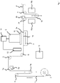
- the Fig.1 shows a schematic representation of an arrangement of functional components for a device for printing a continuous material 1 from a material roll 2.
- the device for printing (printing device) can be formed in one embodiment from the components shown.
- the continuous material 1 can also be referred to as a print substrate.
- the roll of material 2 serves as a storage device for the endless material 1 .
- the endless material 1 can be a plastic film or a paper material.
- the endless material 1 is a polycarbonate film, for example with a thickness of about 75 ⁇ m and a width of 600 mm.
- the continuous material can consist of a different material, for example PVC, have a greater or smaller thickness, for example 100 ⁇ m, and/or have a smaller or larger width, for example 300 mm.
- the continuous material 1 is moved in a feed direction 4 through the printing device by means of a printing table 3 and is thereby unwound from the material roll 2 .
- the printing table 3 can be moved in the feed direction 4 and counter to the feed direction 4 .
- the printing table 3 can be designed as a coherent unit or at least move as a unit in order to support a feed of the continuous material 1 that is uniform across the width of the continuous material 1 .
- the printing table 3 has a holding or fixing device, by means of which the continuous material 1 is held, for example in that the continuous material 1 is sucked in in the area of a support surface 3a of the printing table 3 .
- the printing table 3 moves in the feed direction 4 from a rear position to a front position and thus pulls the continuous material 1 from the material roll 2 in the feed direction 4 through the printing device.
- the holding device then releases the endless material 1 so that it is detached from the printing table 3 .
- the printing table 3 then moves against the feed direction 4 past the endless material 1 from the front to the rear position and then makes contact with the endless material 1 again by means of the holding device, whereupon the movement of the printing table 3 in the feed direction 4 is repeated. A discontinuous advancement of the continuous material 1 through the printing device is thus provided.
- additional drive mechanisms can be provided, which support the movement of the continuous material 1 provided by the printing table 3 .
- driven rollers over which the continuous material 1 runs and which move the continuous material 1 in a supporting manner, can be arranged in front of and/or behind the printing table 3 along a web path of the continuous material 1 .
- an assisting drive mechanism may be arranged along the web path of the continuous material 1 behind the printing table 3 to assist movement of the continuous material 1 away from the printing table 3 .
- a print head shuttle 5 is arranged on a side of the endless material 1 opposite the printing table 3 .
- the print head shuttle 5 is arranged opposite the printing table 3 in such a way that the continuous material 1 runs between the printing table 3 and the print head shuttle 5, so that it can be printed using the print head shuttle 5, or print head for short, while it rests on the printing table 3 and from the holding device is held.
- the printing table 3 moves the continuous material past the print head shuttle 5 in the feed direction 4 .
- the print head shuttle 5 prints the endless material 1.
- the continuous material 1 runs over a plurality of deflection rollers 6, by means of which the continuous material 1 is deflected.
- the endless material 1 also runs over web tension measuring rollers 7, by means of which a web tension of the endless material 1 is measured.
- a first web tension measuring roller 7a is arranged along the web path of the endless material 1 in front of the printing table 3 .
- the first web tension measuring roller 7a thus measures the web tension of the continuous material 1 in front of the printing table 3.
- a web tension of the endless material 1 can occur along the web path of the endless material 1 behind the printing table 3, which is independent of the web tension in front of the printing table 3.
- a second web tension measuring roller 7b is arranged along the web path of the endless material 1 behind the printing table. The second web tension measuring roller 7b thus measures the web tension of the endless material 1 behind the printing table 3.
- the web tension of the endless material 1 causes a respective force on the axes of the web tension measuring rollers 7a, 7b.
- a respective sensor device 8a, 8b of Web tension measuring rollers 7a, 7b measure the respective force on the axis of the web tension measuring rollers 7a, 7b.
- the respective sensor device 8a, 8b of the first 7a and the second 7b web tension measuring roller generates first or second measurement data which indicate the respective web tension of the endless material 1 on the first web tension measuring roller 7a or on the second web tension measuring roller 7b.
- the endless material runs over so-called dancers 9a, 9b. These are rollers which are movably arranged in order to adjust the tension of the endless material 1 .
- a first dancer 9a can be seen along the path of the endless material 1 in front of the printing table.
- the first dancer 9a can be moved up and down, with a downward movement of the first dancer 9a leading to an increase in the tension of the endless material 1 and an upward movement of the first dancer 9a leading to a reduction in the tension of the endless material 1 leads.
- the web tension of the endless material 1 in front of the printing table 3 can thus be adjusted by means of the first dancer 9a.
- a second dancer 9b is arranged behind the printing table 3 along the web path of the continuous material 1 .
- the second dancer 9b can also be moved up and down in the example shown, with a downward movement of the second dancer 9b leading to an increase in the tension of the endless material 1 and an upward movement of the second dancer 9b leading to a reduction in the tension of the endless material 1 leads.
- the web tension of the continuous material 1 behind the printing table 3 can thus be adjusted by means of the second dancer 9b, which is independent of the web tension in front of the printing table 3 at least while the continuous material 1 is being held by the holding device on the printing table 3.
- a control device 10 is connected to the web tension measuring rollers 7a, 7b and the dancers 9a, 9b (not shown) and is set up to receive the first and the second measurement data from the web tension measuring rollers 7a, 7b.
- the first measurement data are compared with a first specified web tension.
- the first specified web tension specifies a desired web tension of the continuous material 1 along the web path of the continuous material 1 in front of the printing table.
- the control device 10 generates first control data corresponding to the comparison result, which are transmitted to the first dancer 9a and lead to a movement of the first dancer 9a.
- the first control data indicates a small downward movement of the first dancer 9a when the comparison shows that the web tension of the continuous material indicates of the first web tension measuring roller 7a deviates downwards by a small difference from the first predetermined web tension and the first control data indicate a greater upward movement of the first dancer 9a if the comparison shows that the web tension of the endless material on the first web tension measuring roller 7a is by a greater Difference upwards from the first specified web tension.
- the control device 10 can also be set up to compare the second measurement data with a second predefined web tension.
- the second specified web tension indicates a desired web tension of the continuous material 1 along the web path of the continuous material 1 behind the printing table.
- the control device 10 generates second control data corresponding to the comparison result, which are transmitted to the second dancer 9b and lead to a movement of the second dancer 9b.
- the second control data indicate, for example, a small movement of the second dancer 9b downwards if the comparison shows that the web tension of the continuous material on the second web tension measuring roller 7b has fallen by a small difference from the second predetermined one Web tension deviates and the second control data indicate a greater upward movement of the second dancer 9b if the comparison shows that the web tension of the endless material on the second web tension measuring roller 7b deviates upwards by a greater difference from the second predetermined web tension.
- the web tensions upstream and downstream of the printing table 3 can be continuously monitored by repeatedly receiving first and second measurement data and generating corresponding first and second control data.
- the web tension in the printing device can be regulated along the web path of the continuous material 1 both in front of and behind the printing table 3 .
- the first and the second specified web tension can be the same and the web tension of the continuous material 1 can be regulated both in front of and behind the printing table 3 in such a way that the same web tension of the continuous material 1 is achieved in front of and behind the printing table 3 within a specified permissible deviation.
- the print head shuttle 5 is set up to print the endless material 1 according to a print layout.
- a print control by means of a print head control device 11, which is also connected to a measuring device 12, which is designed, for example, as an optical measuring device with an array of optical sensors and/or a camera.
- the measuring device 12 is in the feed direction 4 in an area between the material roll 2 and the printing table 3 in front of the printing table 3.
- a reference mark which extends on the continuous material 1 in the area of the print section 1a to be printed in the feed direction 4, is detected with the aid of the measuring device 12.
- the reference marking can be, for example, a line marking that extends in the longitudinal direction (advance direction 4) of the endless material 1, in particular in an outer edge region 12 of the endless material 1 (cf. 2 ). In this way, a control line can be provided, which is detected by the measuring device 12 as a reference mark.
- the reference mark can be detected by means of an image data analysis of images recorded by the measuring device 12 when the printing section 1a of the endless material 1 is guided past the measuring device 12, which takes place before the printing section 1a then reaches the printing table 3 and is placed thereon.
- the measurement signals/data recorded for the reference marking on the continuous material 1 are evaluated by the print head control device 11 in order to determine whether a position deviation in relation to a reference position can be determined for the reference marking in the area of the printing section 1a, with this being indicated in the Reference data indicative of the reference position are provided to print head controller 11. This is done, for example, using image data analysis.
- a position of the detected reference marking along a line or line sensor arrangement of the measuring device 12 extending transversely to the feed direction 4 can be detected and compared with the reference position.
- the print head control device 11 is used to determine a corrected print layout which, based on a print layout previously provided in the print head control device 11, is positioned with regard to the positioning of the print layout in the direction transverse to the Feed device 4 is corrected.
- a coordinate origin of a coordinate system assigned to the print layout is corrected in the direction transverse to the feed direction 4 .
- the print section 1a of the continuous material 1 is printed according to the corrected print layout, in particular by means of an inkjet printing process.
- the print head shuttle 5 has a smoothing device with a brush 15 which extends along a longitudinal direction which runs parallel to the feed direction 4 .
- the brush 15 as a functional part of the smoothing device is thus elongated in the longitudinal direction, parallel to the feed direction 4 . It therefore has a greater extent in the longitudinal direction than in other directions.
- the smoothing device can have a smoothing effect transversely to the feed direction 4 when moving over the endless material 1 .
- an embodiment without a smoothing device can be provided.
- the brush 15 is arranged laterally on the print head shuttle 5 in relation to the direction of movement of the print head shuttle 5 .
- the brush 15 is movable up and down relative to the print head shuttle 5 between first and second positions.
- the brush 15 comes into contact with the support surface 3a, so that when the print head shuttle 5 moves transversely to the feed direction 4, the brush 15 sweeps over the endless material 1 arranged on the support surface 3a of the printing table 3.
- the brush 15 is arranged above the printing table 3 in such a way that the brush 15 does not touch either the printing table 3 or the endless material 1 when the print head shuttle 5 moves.
- a connection is formed between the endless material 1 and the supporting surface 3a by means of a suction device.
- the print head shuttle 5 While the print head shuttle 5 is in a first module position, in which the print head shuttle 5 and the brush 15 are arranged to the right of the printing table 3, the brush 15 is brought into the first position.
- the brush 15 sweeps over the continuous material 1 and thus smooths out wrinkles and/or bubbles that appear in the continuous material 1 during the formation of the contact between the bearing surface 13 and the continuous material 1 and/or during the heating of the endless material 1 by means of a heating device (not shown).
- the brush 15 After the brush 15 has been moved over the entire width of the continuous material 1, the brush 15 is brought to the second position. During subsequent movements of the print head shuttle 5, during the movement of the printing table 3 from the rear to the front position, the brush 15 does not come into contact with the continuous material 1. After the continuous material 1 has been detached from the printing table 3 and the printing table 3 has been moved from the front to the rear position, a connection is formed again between the continuous material 1 and the support surface 3a and the brush 15 is moved to the first position. Thus, the continuous material is smoothed by the brush 15 during the first subsequent movement of the print head shuttle 5 over the continuous material 1 after each contact is made with the bearing surface 3a of the printing table 3 .
- the brush 15 can have a length which corresponds at least to the length of the bearing surface 3a of the printing table 3.
- the length of the brush 15 can be greater than a length of the print head shuttle 5, which can be shorter than the length of the bearing surface 3a. It is thus ensured that the continuous material 1 is smoothed by the brush 15 over the entire length on which contact is made with the bearing surface 3a of the printing table 5 .
- drying devices 16a, 16b are shown along the web path of the endless material 1 behind the printing table 3 and in the area of the second web tension measuring roller 7b and the second dancer 9b.
- the (printed) printing medium on the continuous material 1 is dried by means of the drying devices 16a, 16b.
- the drying devices 16a, 16b can be hot air blowers and/or UV radiators. Different drying devices 16a, 16b can be provided.
Abstract
Description
- Die Erfindung betrifft ein Verfahren und eine Vorrichtung zum Bedrucken eines Endlosmaterials von einer Rolle.
- Beim Bedrucken von Endlosmaterial von einer Materialrolle wird das zu bedruckende Endlosmaterial üblicherweise von der Materialrolle einer Druckereinrichtung zugeführt, um dort abschnittsweise bedruckt zu werden. Das Endlosmaterial wird mittels einer Zuführeinrichtung der Druckereinrichtung zugeführt, derart, dass beispielsweise Abschnitt für Abschnitt des Endlosmaterial auf einen Drucktisch angeordnet wird, der eine Unterlage für das Endlosmaterial bildet, um den jeweils auf den Drucktisch angeordneten Abschnitt des Endlosmaterials dann mittels eines Druckkopfs zu bedrucken. Auf diese Weise können beispielsweise Folienmaterialien für die Herstellung von Identitätisdokumenten (ID-Dokumenten) bedruckt werden, wobei das bedruckte Folienmaterial anschließend in einen Ausweis oder eine Ausweiskarte integriert werden kann.
- Ein Verfahren und eine Vorrichtung zum Bedrucken eines Endlosmaterials sind beispielsweise im Dokument
EP 3 693 178 A1 offenbart. - Auch im Dokument
DE 10 2009 003 445 A1 sind ein Verfahren und eine Vorrichtung zum Bedrucken eines Endlosmaterials beschrieben. Das Endlosmaterial wird einem Drucklayout entsprechend bedruckt, so dass ein Druckbild auf dem Endlosmaterial hergestellt wird. Hierbei ist auf die korrekte Positionierung des Drucklayouts in Bezug auf den zu bedruckenden Abschnitt des Endlosmaterials zu achten. Um fehlerhafte Druckbilder zu korrigieren, ist bei dem bekannten Verfahren eine optische Erfassungseinrichtung vorgesehen, mittels der die fixierte Position des Abschnitts des Endlosmaterials auf dem Drucktisch sowie die genaue Position eines ersten Druckbildes erfasst werden, nachdem der zu bedruckende Abschnitt des Endlosmaterials auf dem Drucktisch fixiert ist und mit dem ersten Druckbild bedruckt ist. Der mit einem Schlitten gebildete Drucktisch ist hierauf zur Korrektur senkrecht zur Vorschubrichtung des Endlosmaterials beim Zuführen zur Druckereinrichtung geringfügig verfahrbar. Des Weiteren ist der Schlitten um eine Drehachse geringfügig verschwenkbar. Hierauf kann dann ein nachfolgender Abschnitt des zu bedruckenden Materials mit einem ersten Druckbild bedruckt werden. - Das Dokument
JP 2009 190 268 A - In dem Dokument
JP 2012 078 545 A - Das Dokument
US 4,485,982 betrifft ein Bahnverfolgungssystem für eine kontinuierliche Materialbahn, die über eine oder mehrere Bearbeitungsstationen von einem Vorrat zu einer Aufwickeleinrichtung entlang eines vorbestimmten Weges transportiert wird und ausgerichtete Verfolgungsmarkierungen entlang mindestens einer Kante der Bahn umfasst. Es sind Mittel vorgesehen, um die Verfolgungsmarkierungen zu beobachten, während die Bahn entlang des Systemwegs transportiert wird, und um Informationen zu erzeugen, die entweder auf Dimensionsänderungen in der Länge und Breite der Bahn aufgrund von Bahnschrumpfung oder -ausdehnung oder auf einen bestimmten Punkt entlang der Länge der Bahn hinweisen, welcher an einer oder mehreren der Verarbeitungsstationen im System nützlich ist. - Aufgabe der Erfindung ist es, ein Verfahren und eine Vorrichtung zum Bedrucken eines Endlosmaterials von einer Materialrolle anzugeben, bei denen die korrekte Positionierung eines Druckbilds, welches einem Drucklayout entsprechend auf dem Endlosmaterial aufzudrucken ist, verbessert ist.
- Zur Lösung sind ein Verfahren sowie eine Vorrichtung zum Bedrucken eines Endlosmaterials von einer Materialrolle nach den unabhängigen Ansprüche 1 und 13 geschaffen. Ausgestaltungen sind Gegenstand von abhängigen Unteransprüchen.
- Nach einem Aspekt ist ein Verfahren zum Bedrucken eines Endlosmaterials von einer Materialrolle geschaffen, welches Folgendes aufweist: Bereitstellen eines zu bedruckenden Endlosmaterials auf einer Materialrolle; Zuführen des Endlosmaterials von der Materialrolle zu einem Drucktisch mittels Vorschub in einer Vorschubrichtung, umfassend Anordnen eines Druckabschnitts des Endlosmaterials auf dem Drucktisch und Erfassen einer sich in einer Vorschubrichtung erstreckenden Bezugsmarkierung an dem Endlosmaterial im Bereich des Druckabschnitts mittels einer Messeinrichtung vor dem Anordnen des Druckabschnitts auf dem Drucktisch; Bestimmen einer Positionsabweichung der Bezugsmarkierung des Endlosmaterials in Bezug auf eine Referenzposition entlang einer Richtung quer zur Vorschubrichtung mittels einer Steuereinrichtung; Bereitstellen eines Drucklayouts zum Bedrucken des Druckabschnitts in der Steuereinrichtung; Bestimmen eines korrigierten Drucklayouts mittels der Steuereinrichtung, welches hinsichtlich einer Positionierung des Drucklayouts entlang der Richtung quer zur Vorschubrichtung in Abhängigkeit von der Positionsabweichung korrigiert ist; und Bedrucken des Endlosmaterials im Druckabschnitt dem korrigierten Drucklayout entsprechend mittels einer Druckeinrichtung, die beim Bedrucken gemäß dem korrigierten Drucklayout relativ zu dem auf dem Drucktisch angeordneten Druckabschnitt verlagert wird.
- Nach einem weiteren Aspekt ist eine Vorrichtung zum Bedrucken eines Endlosmaterials von einer Materialrolle geschaffen, welche Folgendes aufweist: einer Materialrolle mit einem zu bedruckenden Endlosmaterial; einem Drucktisch, auf dem das Endlosmaterial zum Bedrucken anordenbar ist; einer Messeinrichtung; einer Zuführeinrichtung, die eingerichtet ist, das Endlosmaterial von der Materialrolle dem Drucktisch mittels Vorschub in einer Vorschubrichtung zuzuführen, wobei hierbei ein Druckabschnitt des Endlosmaterials auf dem Drucktisch anordenbar ist und mittels der Messeinrichtung eine sich in der Vorschubrichtung erstreckende Bezugsmarkierung an dem Endlosmaterial im Bereich des Druckabschnitts vor dem Anordnen des Druckabschnitts auf dem Drucktisch erfassbar ist; einer Steuereinrichtung, die eingerichtet ist, eine Positionsabweichung der Bezugsmarkierung des Endlosmaterials in Bezug auf eine Referenzposition entlang einer Richtung quer zur Vorschubrichtung zu bestimmen; ein Drucklayout zum Bedrucken des Druckabschnitts bereitzustellen und ein korrigiertes Drucklayout zu bestimmen, welches hinsichtlich einer Positionierung des Drucklayouts entlang der Richtung quer zur Vorschubrichtung in Abhängigkeit von der Positionsabweichung korrigiert ist; und einer Druckeinrichtung, die eingerichtet ist, das Endlosmaterial im Druckabschnitt dem korrigierten Drucklayout entsprechend zu bedrucken, wobei die Druckeinrichtung hierbei gemäß dem korrigierten Drucklayout relativ zu dem auf dem Drucktisch angeordneten Druckabschnitt verlagerbar ist.
- Mit Hilfe der vorgeschlagenen Technik ist es ermöglicht, das Drucklayout auf dem zu bedruckenden Druckabschnitt des Endlosmaterials korrekt zu positionieren. Für den zu bedruckenden Druckabschnitt wird die Bezugsmarkierung an dem Endlosmaterial mittels der Messeinrichtung erfasst. Besteht eine Positionsabweichung der Bezugsmarkierung in Bezug auf die Referenzposition entlang der Richtung quer zur Vorschubrichtung, wird das korrigierte Drucklayout bestimmt, um dann den Druckabschnitt, für den zuvor konkret die Positionsabweichung bestimmt wurde, dem korrigierten Drucklayout entsprechend zu bedrucken. Im Unterschied zum Stand der Technik wird die mögliche Positionsabweichung also für den Druckabschnitt bestimmt, der dann ggf. mit dem korrigierten Drucklayout bedruckt wird. Die hierfür herangezogenen Messsignale betreffen die Bezugsmarkierung werden mittels der Messeinrichtung vor dem Anordnen des zu bedruckenden Druckabschnitts auf den Drucktisch erfasst, so dass dann das tatsächliche Bedrucken dieses Druckabschnitts dem korrigierten Drucklayout entsprechend erfolgen kann.
- Beim Bestimmen der Positionsabweichung der Bezugsmarkierung des Endlosmaterials in Bezug auf die Referenzposition entlang der Bezugsmarkierung kann weiterhin Folgendes vorgesehen sein: Bestimmen einer jeweiligen örtlichen Positionsabweichung in mehreren in Vorschubrichtung hintereinanderliegenden Messpunkten entlang der Bezugsmarkierung an dem Endlosmaterial und Bestimmen der Positionsabweichung als Mittelwert der örtlichen Positionsabweichungen. Auf diese Weise können unterschiedliche Positionsabweichungen über die Länge des Druckabschnitts in Richtung der Vorschubrichtung berücksichtigt werden, nämlich in gemittelter Form.
- Das Erfassen der Bezugsmarkierung kann das Erfassen einer sich entlang der Vorschubrichtung erstreckenden Linienmarkierung auf dem Endlosmaterial umfassen. Die Linienmarkierung bildet eine Steuerlinie, die mit Hilfe der Messeinrichtung und der Steuereinrichtung erfasst und ausgewertet wird, um das Drucklayout dann in korrigierter Form auf dem Druckabschnitt aufzubringen. Die Linienmarkierung kann durchgehend mit einer einheitlichen Linienform oder mit mehreren Abschnitten unterschiedlicher Linienformen gebildet sein, wozu insbesondere durchgehende Linien sowie gestrichelte Linien gehören können. Beim Bestimmen der Positionsabweichung kann beispielsweise ein Abstand der Linienmarkierung zum sich entlang der Vorschubrichtung erstreckenden Materialrand des Endlosmaterials bestimmt und zum Bestimmen der Positionsabweichung herangezogen werden.
- Das Erfassen der Bezugsmarkierung kann das Erfassen eines sich entlang der Vorschubrichtung erstreckenden Materialrands des Endlosmaterials umfassen. Ergänzend oder alternativ zum Erfassen der Linienmarkierung ist bei dieser Ausführungsform vorgesehen, den äußeren Materialrand im Bereich des Druckabschnitts als Bezugsmarkierung zu erfassen und für die Bestimmung der Positionsabweichung heranzuziehen.
- Das Bestimmen des korrigierten Drucklayouts kann eine Lagekorrektur für einen Koordinatenursprung eines zumindest zweidimensionalen Koordinatensystems, welches dem Drucklayout zugeordnet ist, in der Richtung quer zur Vorschubrichtung umfassen. Die zuvor bestimmte Positionsabweichung in der Richtung quer zur Vorschubrichtung wird für das Bestimmen des korrigierten Drucklayouts derart berücksichtigt, dass der Koordinatenursprung des Koordinatensystems des Drucklayouts verschoben wird. Beispielsweise kann dies die Y-Richtung des Koordinatensystems betreffen, wenn die Vorschubrichtung der X-Richtung des Koordinatensystems entspricht.
- Bei diesen oder anderen Ausführungsformen kann die beim Bedrucken ausgeführte Relativbewegung zwischen dem Druckabschnitt auf dem Drucktisch und dem Druckkopf ausgeführt werden, indem der Drucktisch bei feststehendem Druckkopf oder der Druckkopf bei feststehendem Drucktisch bewegt werden. Die Relativbewegung kann auch das Bewegen sowohl des Druckkopfs wie auch des Drucktischs umfassen.
- Zumindest einer der folgenden Schritte kann vor einem ortsfesten Positionieren oder Fixieren des Druckabschnitts beim Anordnen auf dem Drucktisch wenigstens begonnen werden: Bestimmen der Positionsabweichung der Bezugsmarkierung des Endlosmaterials in Bezug auf die Referenzposition entlang der Richtung quer zur Vorschubrichtung und Bestimmen des korrigierten Drucklayouts. Hierdurch ist eine Echtzeitverarbeitung der Messsignale von der Messeinrichtung betreffend die Bezugsmarkierung an dem Endlosmaterial ausgeführt. Das Bestimmen der Positionsabweichung kann unmittelbar im Anschluss an das zuvor erfolgte Erfassen der Bezugsmarkierung mittels der Messeinrichtung begonnen werden. Zumindest einer der beiden Schritte kann abgeschlossen sein, bevor der Druckabschnitt beim Vorschub des Endlosmaterials den Drucktisch erreicht oder bevor der Druckabschnitt auf dem Drucktisch fixiert wird.
- Bei dieser oder anderen Ausführungsformen kann der Druckabschnitt mittels einer Fixiereinrichtung beim Bedrucken an dem Drucktisch fixiert werden. Hierzu kann die Fixiereinrichtung zum Beispiel eine Ansaug- oder Vakuumeinrichtung aufweisen, mit der der Druckabschnitt des Endlosmaterials zumindest während des Bedruckens gemäß dem korrigierten Drucklayout an der Oberfläche des Drucktischs angesaugt wird. Nach dem Bedrucken wird die Fixierung des Endlosmaterials im Druckabschnitt an dem Drucktisch gelöst, so dass ein folgender Druckabschnitt des Endlosmaterials dem Drucktisch zugeführt und hieran fixiert werden kann.
- Die Messeinrichtung kann in Vorschubrichtung vor dem Drucktisch angeordnet sein, und die Bezugsmarkierung an dem Endlosmaterial im Druckabschnitt kann mittels der Messeinrichtung erfasst werden, bevor beim Vorschub der Druckabschnitt den Drucktisch erreicht. Der Druckabschnitt passiert im Wege des Vorschubs des Endlosmaterials einen Erfassungsbereich der Messeinrichtung bevor der Druckabschnitt den Drucktisch erreicht. Alternativ kann vorgesehen sein, dass das Erfassen der Bezugsmarkierung an dem Endlosmaterial mittels der Messeinrichtung noch andauert, wenn zumindest ein vorderer Abschnitt des Druckabschnitts den Drucktisch schon erreicht hat, ohne hierauf schon fixiert zu sein, Bei dieser Ausgestaltung beginnt das Erfassen der Bezugsmarkierung an dem Endlosmaterial im Bereich des Druckabschnitts bevor der Druckabschnitt den Drucktisch erreicht, endet jedoch erst, wenn der vordere Abschnitt des Druckabschnitts schon in den Bereich des Drucktischs gelangt ist, insbesondere oberhalb einer Auflagefläche des Drucktischs angeordnet ist.
- Als Messeinrichtung kann eine optische Messeinrichtung verwendet werden. Die optische Messeinrichtung kann mit einer Anordnung von Sensoren gebildet sein, beispielsweise in Form einer Linien-Sensoranordnung, welche sich quer zur Vorschubrichtung erstrecken kann. Alternativ oder ergänzend kann die optische Messeinrichtung eine Kamera umfassen, die eingerichtet ist, für den Druckabschnitt ein oder mehrere Bildaufnahmen zu erfassen, die anschließend mit einer Bildanalyse ausgewertet werden, um schließlich die Positionsabweichung zu bestimmen.
- Das Endlosmaterial kann von der Materialrolle über den Drucktisch zu einer Aufnahmerolle transportiert werden. Hierdurch kann eine Verfahrensweise der Bearbeitung von Rolle-zu-Rolle erfolgen.
- Als Endlosmaterial kann ein Material aus der folgenden Gruppe verwendet und bedruckt werden: Folienmaterial und Papiermaterial. Bei dieser oder anderen Ausführungsformen kann vorgesehen sein, auf dem Druckabschnitt dem korrigierten Drucklayout entsprechend ein oder mehrere getrennte Druckbilder aufzudrucken.
- Beim Bedrucken des Druckabschnitts kann mit dem Drucklayout ein Ausweisdrucklayout aufgedruckt werden. Beispielsweise kann vorgesehen sein, auf einem Folienmaterial mehrere getrennte Ausweisdruckbilder aufzubringen, zum Beispiel ein Gesichtsbild sowie einen alphanummerischen Code. Im Anschluss an das Bedrucken können Folienabschnitte mit dem jeweiligen Ausweisdruckbild von dem Druckabschnitt getrennt werden, um die so hergestellten getrennten Folienabschnitte dann in ein ID-Dokument zu integrieren, beispielsweise dadurch, dass mehrere Folienschichten aufeinander laminiert werden, wie dies in verschiedenen Ausführungsformen als solches bekannt ist. Auf diese Weise kann ein Verfahren zum Herstellen eines beliebigen ID-Dokuments ausgeführt werden, welches das Verfahren zum Bedrucken umfasst.
- Die Druckeinrichtung kann einen Inkjet-Druckkopf aufweisen, und das Drucklayout kann mittels des Inkjet-Druckkopfs auf den Druckabschnitt gedruckt werden.
- Die vorangehend im Zusammenhang mit dem Verfahren zum Bedrucken erläuterten Ausgestaltungen können entsprechend bei der Vorrichtung zum Bedrucken des Endlosmaterials von der Materialrolle vorgesehen sein.
- Im Folgenden werden weitere Ausführungsbeispiele unter Bezugnahme auf Figuren einer Zeichnung erläutert. Hierbei zeigen:
- Fig. 1
- eine schematische Darstellung einer Anordnung von funktionellen Komponenten für eine Vorrichtung zum Bedrucken (Druckvorrichtung) eines Endlosmaterials von einer Materialrolle und
- Fig. 2
- eine schematische perspektivische Darstellung einer Anordnung für eine Vorrichtung zum Bedrucken eines Endlosmaterials.
- Die
Fig.1 zeigt eine schematische Darstellung einer Anordnung von funktionellen Komponenten für eine Vorrichtung zum Bedrucken eines Endlos- oder Endlosmaterials 1 von einer Materialrolle 2. Die Vorrichtung zum Bedrucken (Druckvorrichtung) kann in einer Ausgestaltung von den dargestellten Komponenten gebildet sein. - Das Endlosmaterial 1 kann auch als Drucksubstrat bezeichnet werden. Die Materialrolle 2 dient als Speichereinrichtung für das Endlosmaterial 1 dient. Bei dem Endlosmaterial 1 kann es sich um eine Kunststofffolie oder ein Papiermaterial handeln. In einem Beispiel handelt es sich bei dem Endlosmaterial 1 um eine Polycarbonat-Folie, zum Beispiel mit einer Dicke von etwa 75 µm und einer Breite von 600 mm. In weiteren Beispiel kann das Endlosmaterial aus einem anderen Werkstoff bestehen, beispielsweise PVC, eine größere oder kleinere Dicke haben, beispielsweise 100 µm, und / oder eine kleinere oder größere Breite haben, beispielsweise 300 mm.
- Das Endlosmaterial 1 wird im gezeigten Ausführungsbeispiel mittels eines Drucktischs 3 in einer Vorschubrichtung 4 durch die Druckvorrichtung bewegt und hierdurch von der Materialrolle 2 abgewickelt. Hierzu ist der Drucktisch 3 in die Vorschubrichtung 4 sowie entgegen der Vorschubrichtung 4 beweglich. Der Drucktisch 3 kann als zusammenhängende Einheit ausgebildet sein oder sich zumindest als eine Einheit bewegen, um einen über die Breite des Endlosmaterials 1 hinweg gleichmäßigen Vorschub des Endlosmaterials 1 zu unterstützen. Der Drucktisch 3 weist eine Halte- oder Fixiereinrichtung auf, mittels derer das Endlosmaterial 1 gehalten wird, beispielsweise dadurch, dass das Endlosmaterial 1 im Bereich einer Auflagefläche 3a des Drucktischs 3 angesaugt wird.
- Während das Endlosmaterial 1 mittels der Halteeinrichtung an dem Drucktisch 3 gehalten wird, bewegt sich der Drucktisch 3 in die Vorschubrichtung 4 von einer hinteren Stellung in eine vordere Stellung und zieht so das Endlosmaterial 1 von der Materialrolle 2 in Vorschubrichtung 4 durch die Druckvorrichtung. Anschließend gibt die Halteeinrichtung das Endlosmaterial 1 frei, so dass dieses von dem Drucktisch 3 gelöst ist. Der Drucktisch 3 bewegt sich dann entgegen der Vorschubrichtung 4 an dem Endlosmaterial 1 vorbei von der vorderen in die hintere Stellung und bildet anschließend mittels der Halteeinrichtung erneut einen Kontakt zu dem Endlosmaterial 1 aus, worauf sich die Bewegung des Drucktischs 3 in die Vorschubrichtung 4 wiederholt. Es ist so eine diskontinuierliche Fortbewegung des Endlosmaterials 1 durch die Druckvorrichtung bereitgestellt.
- In weiteren Ausgestaltungen können zusätzliche Antriebsmechanismen vorgesehen sein, welche die mittels des Drucktischs 3 bereitgestellte Fortbewegung des Endlosmaterials 1 unterstützen. Beispielsweise können angetriebene Rollen, über die das Endlosmaterial 1 verläuft und welche das Endlosmaterial 1 unterstützend fortbewegen, entlang eines Bahnwegs des Endlosmaterials 1 vor und / oder hinter dem Drucktisch 3 angeordnet sein. Insbesondere kann ein unterstützender Antriebsmechanismus entlang des Bahnwegs des Endlosmaterials 1 hinter dem Drucktisch 3 angeordnet sein, um eine Bewegung des Endlosmaterials 1 von dem Drucktisch 3 weg zu unterstützen.
- Auf einer dem Drucktisch 3 gegenüberliegenden Seite des Endlosmaterials 1 ist ein Drucckopfshuttle 5 angeordnet. Das Druckkopfshuttle 5 ist dem Drucktisch 3 derart gegenüberliegend angeordnet, dass das Endlosmaterial 1 zwischen dem Drucktisch 3 und dem Drucckopfshuttle 5 verläuft, sodass es mittels des Druckkopfshuttles 5, kurz Druckkopf, bedruckt werden kann, während es auf dem Drucktisch 3 aufliegt und von der Halteeinrichtung gehalten wird. Der Drucktisch 3 bewegt das Endlosmaterial in der Vorschubrichtung 4 an dem Druckkopfshuttle 5 vorbei. Während der Bewegung des Endlosmaterials bedruckt das Druckkopfshuttle 5 das Endlosmaterial 1.
- Bei der Bewegung verläuft das Endlosmaterial 1 über mehrere Umlenkrollen 6, mittels derer das Endlosmaterial 1 umgelenkt wird. Das Endlosmaterial 1 verläuft auch über Bahnspannungsmessrollen 7, mittels derer eine Bahnspannung des Endlosmaterials 1 gemessen wird. Wie in der
Fig. 1 gezeigt, ist beim gezeigten Beispiel eine erste Bahnspannungsmessrolle 7a entlang des Bahnwegs des Endlosmaterials 1 vor dem Drucktisch 3 angeordnet. Die erste Bahnspannungsmessrolle 7a misst somit die Bahnspannung des Endlosmaterials 1 vor dem Drucktisch 3. - Durch das Halten des Endlosmaterials 1 mittels der Halteeinrichtung an dem Drucktisch 3 kann entlang des Bahnwegs des Endlosmaterials 1 hinter dem Drucktisch 3 eine Bahnspannung des Endlosmaterials 1 auftreten, welche von der Bahnspannung vor dem Drucktisch 3 unabhängig ist. Aus diesem Grund ist eine zweite Bahnspannungsmessrolle 7b entlang des Bahnwegs des Endlosmaterials 1 hinter dem Druck-tisch angeordnet. Die zweite Bahnspannungsmessrolle 7b misst somit die Bahnspannung des Endlosmaterials 1 hinter dem Drucktisch 3.
- Die Bahnspannung des Endlosmaterials 1 verursacht eine jeweilige Kraft auf die Achsen der Bahnspannungsmessrollen 7a, 7b. Mittels einer jeweiligen Sensoreinrichtung 8a, 8b der Bahnspannungsmessrollen 7a, 7b wird die jeweilige Kraft auf die Achse der Bahnspannungsmessrollen 7a, 7b gemessen. Die jeweilige Sensoreinrichtung 8a, 8b der ersten 7a und der zweiten 7b Bahnspannungsmessrolle erzeugt erste bzw. zweite Messdaten, welche die jeweilige Bahnspannung des Endlosmaterials 1 an der ersten Bahnspannungsmessrolle 7a bzw. an der zweiten Bahnspannungsmessrolle 7b angeben.
- Weiterhin verläuft das Endlosmaterial über sogenannte Tänzer 9a, 9b. Hierbei handelt es sich um Rollen, welche beweglich angeordnet sind, um eine Spannung des Endlosmaterials 1 einzustellen. Wie in der
Fig. 1 zu erkennen ist ein erster Tänzer 9a entlang des Bahnwegs des Endlosmaterials 1 vor dem Drucktisch angeordnet. Der erste Tänzer 9a ist in dem gezeigten Beispiel nach oben und unten beweglich, wobei eine Bewegung des ersten Tänzers 9a nach unten zu einer Erhöhung der Spannung des Endlosmaterials 1 führt und eine Bewegung des ersten Tänzers 9a nach oben zu einer Verringerung der Spannung des Endlosmaterials 1 führt. Somit lässt sich mittels des ersten Tänzers 9a die Bahnspannung des Endlosmaterials 1 vor dem Drucktisch 3 einstellen. - Ein zweiter Tänzer 9b ist entlang des Bahnwegs des Endlosmaterials 1 hinter dem Drucktisch 3 angeordnet. Auch der zweite Tänzer 9b ist in dem gezeigten Beispiel nach oben und unten beweglich, wobei eine Bewegung des zweiten Tänzers 9b nach unten zu einer Erhöhung der Spannung des Endlosmaterials 1 führt und eine Bewegung des zweiten Tänzers 9b nach oben zu einer Verringerung der Spannung des Endlosmaterials 1 führt. Somit lässt sich mittels des zweiten Tänzers 9b die Bahnspannung des Endlosmaterials 1 hinter dem Drucktisch 3 einstellen, welche zumindest während des Haltens des Endlosmaterials 1 mittels der Halteeinrichtung an dem Drucktisch 3 von der Bahnspannung vor dem Drucktisch 3 unabhängig ist.
- Eine Steuervorrichtung 10 ist mit den Bahnspannungsmessrollen 7a, 7b und den Tänzern 9a, 9b verbunden (nicht gezeigt) und eingerichtet, die ersten und die zweiten Messdaten von den Bahnspannungsmessrollen 7a, 7b zu empfangen. In der Steuervorrichtung 10 werden die ersten Messdaten mit einer ersten vorgegebenen Bahnspannung verglichen. Die erste vorgegeben Bahnspannung gibt eine gewünschte Bahnspannung des Endlosmaterials 1 entlang des Bahnwegs des Endlosmaterials 1 vor dem Drucktisch an. Die Steuervorrichtung 10 erzeugt dem Vergleichsergebnis entsprechende erste Steuerdaten, die an den ersten Tänzer 9a übertragen werden und zu einer Bewegung des ersten Tänzers 9a führen. Beispielsweise geben die ersten Steuerdaten eine kleine Bewegung des ersten Tänzers 9a nach unten an, wenn der Vergleich ergibt, dass die Bahnspannung des Endlosmaterials an der ersten Bahnspannungsmessrolle 7a um eine kleine Differenz nach unten von der ersten vorgegebenen Bahnspannung abweicht und die ersten Steuerdaten geben eine größere Bewegung des ersten Tänzers 9a nach oben an, wenn der Vergleich ergibt, dass die Bahnspannung des Endlosmaterials an der ersten Bahnspannungsmessrolle 7a um eine größere Differenz nach oben von der ersten vorgegebenen Bahnspannung abweicht.
- Die Steuervorrichtung 10 kann weiter eingerichtet sein, die zweiten Messdaten mit einer zweiten vorgegebenen Bahnspannung zu vergleichen. Die zweite vorgegeben Bahnspannung gibt eine gewünschte Bahnspannung des Endlosmaterials 1 entlang des Bahnwegs des Endlosmaterials 1 hinter dem Drucktisch an. Die Steuervorrichtung 10 erzeugt dem Vergleichsergebnis entsprechende zweite Steuerdaten, die an den zweiten Tänzer 9b übertragen werden und zu einer Bewegung des zweiten Tänzers 9b führen. Wie oben bezüglich des ersten Tänzers 9a erläutert, geben beispielsweise die zweiten Steuerdaten eine kleine Bewegung des zweiten Tänzers 9b nach unten an, wenn der Vergleich ergibt, dass die Bahnspannung des Endlosmaterials an der zweiten Bahnspannungsmessrolle 7b um eine kleine Differenz nach unten von der zweiten vorgegebenen Bahnspannung abweicht und die zweiten Steuerdaten geben eine größere Bewegung des zweiten Tänzers 9b nach oben an, wenn der Vergleich ergibt, dass die Bahnspannung des Endlosmaterials an der zweiten Bahnspannungsmessrolle 7b um eine größere Differenz nach oben von der zweiten vorgegebenen Bahnspannung abweicht.
- Es kann eine kontinuierliche Überwachung der Bahnspannungen vor und hinter dem Drucktisch 3 erfolgen, indem wiederholt erste und zweite Messdaten empfangen und entsprechende erste und zweite Steuerdaten erzeugt werden. Hierdurch kann eine Regelung der Bahnspannung in der Druckvorrichtung, entlang des Bahnwegs des Endlosmaterials 1 sowohl vor als auch hinter dem Drucktisch 3, bereitgestellt sein. Beispielsweise können die erste und die zweite vorgegebene Bahnspannung gleich sein und die Bahnspannung des Endlosmaterials 1 sowohl vor als auch hinter dem Drucktisch 3 derart geregelt sein, dass vor und hinter dem Drucktisch 3 die gleiche Bahnspannung des Endlosmaterials 1 innerhalb einer vorgegeben zulässigen Abweichung erreicht wird.
- Das Druckkopfshuttle 5 ist eingerichtet, das Endlosmaterial 1 einem Drucklayout entsprechend zu bedrucken. Hierzu eine Drucksteuerung mittels einer Druckkopf-Steuereinrichtung 11, die weiterhin mit einer Messeinrichtung 12 verbunden ist, welche beispielsweise als eine optische Messeinrichtung mit einer Anordnung optischer Sensoren und / oder einer Kamera ausgeführt ist. Die Messeinrichtung 12 ist bei der gezeigten Ausführungsform in der Vorschubrichtung 4 in einem Bereich zwischen der Materialrolle 2 und dem Drucktisch 3 vor dem Drucktisch 3 angeordnet.
- Um das Endlosmaterial 1 zu bedrucken, werden nacheinander Druckabschnitte des Endlosmaterials 1 auf dem Drucktisch 3 angeordnet und hierauf für den Vorgang des Bedruckens fixiert. Beim Bedrucken werden dann Drucktisch 3 mit einem hierauf angeordnetem Druckabschnitt 1a des Endlosmaterials 1 und Druckkopfshuttle 5 relativ zueinander bewegt, um den Druckabschnitt 1a einem Drucklayout entsprechend zu bedrucken.
-
Fig. 2 zeigt eine weitere Anordnung für eine Vorrichtung zum Bedrucken des Endlosmaterials 1. Für gleiche Merkmale sind inFig. 2 dieselben Bezugszeichnen wie inFig. 1 verwendet. Das Endlosmaterial 1 wird über die Umlenkrollen 6 dem Drucktisch 3 zugeführt. Zur Vereinfachung der Darstellung ist der Druckkopf 5 inFig. 2 weggelassen. Zwischen den Umlenkrollen 6 wird das Endlosmaterial 1 an der Messeinrichtung 12 vorbeigeführt. Nach dem Bedrucken wird das Endlosmaterial 1 über eine Abführrolle 13 abgeführt. - Zum korrekten Bedrucken des Druckabschnitts 1a des Endlosmaterials 1 dem Drucklayout entsprechend ist vorgesehen, dass mit Hilfe der Messeinrichtung 12 eine Bezugsmarkierung, die sich an dem Endlosmaterial 1 im Bereich des zu bedruckenden Druckabschnitts 1a in der Vorschubrichtung 4 erstreckt, erfasst wird. Bei der Bezugsmarkierung kann es sich beispielsweise um eine Linienmarkierung handeln, die sich in Längsrichtung (Vorschubrichtung 4) des Endlosmaterials 1 erstreckt, insbesondere in einem äußeren Randbereich 12 des Endlosmaterials 1 (vgl.
Fig. 2 ). Hierdurch kann eine Steuerlinie bereitgestellt sein, die als Bezugsmarkierung mittels der Messeinrichtung 12 detektiert wird. Weist die Messeinrichtung 12 eine Kamera auf, kann das Detektieren der Bezugsmarkierung mittels einer Bilddatenanalyse von Bildaufnahmen erfolgen, die mittels der Messeinrichtung 12 erfasst werden, wenn der Druckabschnitt 1a des Endlosmaterials 1 an der Messeinrichtung 12 vorbeigeführt wird, was erfolgt, bevor der Druckabschnitt 1a dann den Drucktisch 3 erreicht und hierauf angeordnet wird. - Die für die Bezugsmarkierung an dem Endlosmaterial 1 erfassten Messsignale / -daten werden mittels der Druckkopf-Steuereinrichtung 11 ausgewertet, um zu bestimmen, ob für die Bezugsmarkierung im Bereich des Druckabschnitts 1a eine Positionsabweichung in Bezug auf eine Referenzposition festgestellt werden kann, wobei hierfür in der Druckkopf-Steuereinrichtung 11 die Referenzposition anzeigende Referenzdaten bereitgestellt werden. Dieses erfolgt beispielsweise unter Verwendung der Bilddatenanalyse. In einer alternativen Ausführungsform kann eine Position der detektieren Bezugsmarkierung entlang einer sich quer zur Vorschubrichtung 4 erstreckenden Zeilen- oder Liniensensoranordnung der Messeinrichtung 12 erfasst und mit der Referenzposition verglichen werden.
- Wird eine Positionsabweichung für die Bezugsmarkierung des Endlosmaterials 1 im Druckabschnitt 1a festgestellt, erfolgt mittels der Druckkopf-Steuereinrichtung 11 das Bestimmen eines korrigierten Drucklayouts, welches ausgehend von einem zuvor in der Druckkopf-Steuereinrichtung 11 bereitgestellten Drucklayouts hinsichtlich der Positionierung des Drucklayouts in der Richtung quer zur Vorschubeinrichtung 4 korrigiert ist. Hierdurch wird beispielsweise ein Koordinatenursprung eines dem Drucklayout zugeordneten Koordinatensystems in der Richtung quer zur Vorschubrichtung 4 korrigiert. Sodann wird der Druckabschnitt 1a des Endlosmaterials 1 dem korrigierten Drucklayout entsprechend bedruckt, insbesondere mittels Inkjet-Druckverfahren. Auf diese Weise ist sichergestellt, dass Abweichungen hinsichtlich der Positionierung des Endlosmaterials 1 in Bezug auf den Drucktisch 3 und / oder das Druckshuttle 5 kompensiert werden, derart, dass die Bedruckung dem Drucklayout entsprechend mit korrekter Positionierung des erzeugten Druckbilds auf dem Druckabschnitt 1a des Endlosmaterials 1 erfolgt.
- Bei dem gezeigten Ausführungsbespiel in
Fig. 1 weist das Druckkopfshuttle 5 eine Glättvorrichtung mit einer Bürste 15 auf, welche sich entlang einer Längsrichtung erstreckt, die parallel zu der Vorschubrichtung 4 verläuft. Die Bürste 15 als funktionaler Teil der Glättvorrichtung ist somit in Längsrichtung, parallel zur Vorschubrichtung 4, langgestreckt. Sie weist also in der Längsrichtung eine größere Erstreckung als in andere Richtungen auf. So kann die Glättvorrichtung bei einer Bewegung über das Endlosmaterial 1 quer zur Vorschubrichtung 4 glättend wirken. Alternativ kann eine Ausführung ohne Glättvorrichtung vorgesehen sein. - Im gezeigten Ausführungsbeispiel mit Glättvorrichtung ist die Bürste 15 bezogen auf die Bewegungsrichtung des Druckkopfshuttles 5 seitlich an dem Druckkopfshuttle 5 angeordnet. Die Bürste 15 ist relativ zu dem Druckkopfshuttle 5 nach oben und unten zwischen einer ersten und einer zweiten Stellung beweglich. In der ersten Stellung tritt die Bürste 15 mit der Auflagefläche 3a in Kontakt, so dass die Bürste 15 bei einer Bewegung des Druckkopfshuttles 5 quer zur Vorschubrichtung 4 über das auf der Auflagefläche 3a des Drucktischs 3 angeordnete Endlosmaterial 1 streicht. In der zweiten Stellung ist die Bürste 15 so über dem Drucktisch 3 angeordnet, dass die Bürste 15 bei einer Bewegung des Druckkopfshuttles 5 weder den Drucktisch 3 noch das Endlosmaterial 1 berührt.
- Bei einem Druckvorgang wird, während sich der Drucktisch 3 in der hinteren Stellung befindet, mittels einer Ansaugeinrichtung eine Verbindung zwischen dem Endlosmaterial 1 und der Auflagefläche 3a ausgebildet. Die Bürste 15 wird, während sich das Druckkopfshuttle 5 in einer ersten Modulstellung befindet, in der das Druckkopfshuttle 5 und die Bürste 15 rechts von dem Drucktisch 3 angeordnet sind, in die erste Stellung gebracht. Bei einer anschließenden ersten Bewegung des Druckkopfshuttles 5 über den Drucktisch 3 und das Endlosmaterial 1 streicht die Bürste 15 über das Endlosmaterial 1 und glättet damit Falten und / oder Blasen, die in dem Endlosmaterial 1 während des Ausbildens des Kontakts zwischen der Auflagefläche 13 und dem Endlosmaterial 1 und / oder während des Aufheizens des Endlosmaterials 1 mittels Heizeinrichtung (nicht dargestellt) entstanden sein können.
- Nachdem die Bürste 15 über die gesamte Breite des Endlosmaterials 1 bewegt wurde, wird die Bürste 15 in die zweite Stellung gebracht. Bei anschließenden Bewegungen des Drucckopfshuttles 5, während der Bewegung des Drucktischs 3 von der hinteren in die vordere Stellung, tritt die Bürste 15 somit nicht in Kontakt mit dem Endlosmaterial 1. Nach dem Lösen des Endlosmaterials 1 von dem Drucktisch 3 und der Bewegung des Drucktischs 3 von der vorderen in die hintere Stellung wird erneut eine Verbindung zwischen dem Endlosmaterial 1 und der Auflagefläche 3a ausgebildet und die Bürste 15 in die erste Stellung bewegt. Somit wird das Endlosmaterial nach jedem Ausbilden eines Kontakts mit der Auflagefläche 3a des Drucktischs 3 während der ersten anschließenden Bewegung des Druckkopfshuttles 5 über das Endlosmaterial 1 durch die Bürste 15 geglättet.
- Die Bürste 15 kann eine Länge aufweisen, welche mindestens der Länge der Auflagefläche 3a des Drucktischs 3 entspricht. Hierbei kann, wie in der
Fig. 1 erkennbar, die Länge der Bürste 15 größer sein als eine Länge des Druckkopfshuttles 5, welche kürzer sein kann als die Länge der Auflagefläche 3a. Somit ist sichergestellt, dass das Endlosmaterial 1 durch die Bürste 15 auf der gesamten Länge geglättet wird, auf der ein Kontakt zu der Auflagefläche 3a des Drucktischs 5 hergestellt ist. - Wie in der
Fig. 1 dargestellt sind entlang des Bahnwegs des Endlosmaterials 1 hinter dem Drucktisch 3 und im Bereich der zweiten Bahnspannungsmessrolle 7b und des zweiten Tänzers 9b Trocknungseinrichtungen 16a, 16b angeordnet. Mittels der Trocknungseinrichtungen 16a, 16b wird das (aufgedruckte) Druckmittel auf dem Endlosmaterial 1 getrocknet. Beispielsweise kann es sich bei den Trocknungseinrichtungen 16a, 16b um Heißluftgebläse und / oder UV-Strahler handeln. Es können unterschiedliche Trocknungseinrichtungen 16a, 16b vorgesehen sein. - Die in der vorstehenden Beschreibung, den Ansprüchen sowie der Zeichnung offenbarten Merkmale können sowohl einzeln als auch in beliebiger Kombination für die Verwirklichung der verschiedenen Ausführungen von Bedeutung sein.
-
- 1
- Endlosmaterial
- 2
- Materialrolle
- 3
- Drucktisch
- 3a
- Auflagefläche
- 4
- Vorschubrichtung
- 5
- Druckshuttle
- 6
- Umlenkrolle
- 7a, 7b
- Bahnspannungsmessrolle
- 8a, 8b
- Sensoreinrichtung
- 9a, 9b
- Tänzer
- 10
- Steuervorrichtung
- 11
- Druckkopf-Steuereinrichtung
- 12
- Messeinrichtung
- 13
- Abführrolle
- 14
- äußerer Randbereich
- 15
- Bürste
- 16a, 16b
- Trocknungseinrichtung
Claims (13)
- Verfahren zum Bedrucken eines Endlosmaterials (1) von einer Materialrolle (2), mit- Bereitstellen eines zu bedruckenden Endlosmaterials (1) auf einer Materialrolle (2);- Zuführen des Endlosmaterials (1) von der Materialrolle (2) zu einem Drucktisch (3) mittels Vorschub in einer Vorschubrichtung (4), umfassend- Anordnen eines Druckabschnitts (1a) des Endlosmaterials (1) auf dem Drucktisch (3) und- Erfassen einer sich in einer Vorschubrichtung (4) erstreckenden Bezugsmarkierung an dem Endlosmaterial (1) im Bereich des Druckabschnitts (1a) mittels einer Messeinrichtung (12) vor dem Anordnen des Druckabschnitts (1a) auf dem Drucktisch (3);- Bestimmen einer Positionsabweichung der Bezugsmarkierung des Endlosmaterials (1) in Bezug auf eine Referenzposition entlang einer Richtung quer zur Vorschubrichtung (4) mittels einer Steuereinrichtung (11);- Bereitstellen eines Drucklayouts zum Bedrucken des Druckabschnitts (1a) in der Steuereinrichtung (11);- Bestimmen eines korrigierten Drucklayouts mittels der Steuereinrichtung (11), welches hinsichtlich einer Positionierung des Drucklayouts entlang der Richtung quer zur Vorschubrichtung (4) in Abhängigkeit von der Positionsabweichung korrigiert ist; und- Bedrucken des Endlosmaterials (1) im Druckabschnitt (1a) dem korrigierten Drucklayout entsprechend mittels einer Druckeinrichtung (5), die beim Bedrucken gemäß dem korrigierten Drucklayout relativ zu dem auf dem Drucktisch (3) angeordneten Druckabschnitt (1a) verlagert wird.
- Verfahren nach Anspruch 1, dadurch gekennzeichnet, dass beim Bestimmen der Positionsabweichung der Bezugsmarkierung des Endlosmaterials (1) in Bezug auf die Referenzposition entlang der Bezugsmarkierung weiterhin Folgendes vorgesehen ist:- Bestimmen einer jeweiligen örtlichen Positionsabweichung in mehreren in Vorschubrichtung (4) hintereinanderliegenden Messpunkten entlang der Bezugsmarkierung an dem Endlosmaterial (1) und- Bestimmen der Positionsabweichung als Mittelwert der örtlichen Positionsabweichungen.
- Verfahren nach Anspruch 1 oder 2, dadurch gekennzeichnet, dass das Erfassen der Bezugsmarkierung das Erfassen einer sich entlang der Vorschubrichtung (4) erstreckenden Linienmarkierung auf dem Endlosmaterial (1) umfasst.
- Verfahren nach mindestens einem der vorangehenden Ansprüche, dadurch gekennzeichnet, dass das Erfassen der Bezugsmarkierung das Erfassen eines sich entlang der Vorschubrichtung (4) erstreckenden Materialrands des Endlosmaterials (1) umfasst.
- Verfahren nach mindestens einem der vorangehenden Ansprüche, dadurch gekennzeichnet, dass das Bestimmen des korrigierten Drucklayouts eine Lagekorrektur für einen Koordinatenursprung eines zumindest zweidimensionalen Koordinatensystems, welches dem Drucklayout zugeordnet ist, in der Richtung quer zur Vorschubrichtung (4) umfasst.
- Verfahren nach mindestens einem der vorangehenden Ansprüche, dadurch gekennzeichnet, dass zumindest einer der folgenden Schritte vor einem ortsfesten Positionieren des Druckabschnitts (1a) beim Anordnen auf dem Drucktisch (3) wenigstens begonnen wird:- Bestimmen der Positionsabweichung der Bezugsmarkierung des Endlosmaterials (1) in Bezug auf die Referenzposition entlang der Richtung quer zur Vorschubrichtung (4) und- Bestimmen des korrigierten Drucklayouts.
- Verfahren nach mindestens einem der vorangehenden Ansprüche, dadurch gekennzeichnet, dass die Messeinrichtung (12) in Vorschubrichtung (4) vor dem Drucktisch (3) angeordnet ist und die Bezugsmarkierung an dem Endlosmaterial (1) im Druckabschnitt (1a) mittels der Messeinrichtung (12) erfasst wird, bevor beim Vorschub der Druckabschnitt (1a) den Drucktisch (3) erreicht.
- Verfahren nach mindestens einem der vorangehenden Ansprüche, dadurch gekennzeichnet, dass als Messeinrichtung (12) eine optische Messeinrichtung (12) verwendet wird.
- Verfahren nach mindestens einem der vorangehenden Ansprüche, dadurch gekennzeichnet, dass das Endlosmaterial (1) von der Materialrolle (2) über den Drucktisch (3) zu einer Aufnahmerolle transportiert wird.
- Verfahren nach mindestens einem der vorangehenden Ansprüche, dadurch gekennzeichnet, dass als Endlosmaterial (1) ein Material aus der folgenden Gruppe verwendet und bedruckt wird: Folienmaterial und Papiermaterial.
- Verfahren nach mindestens einem der vorangehenden Ansprüche, dadurch gekennzeichnet, dass beim Bedrucken des Druckabschnitts (1a) mit dem Drucklayout ein Ausweisdrucklayout aufgedruckt wird.
- Verfahren nach mindestens einem der vorangehenden Ansprüche, dadurch gekennzeichnet, dass die Druckeinrichtung (5) einen Inkjet-Druckkopf aufweist und das Drucklayout mittels des Inkjet-Druckkopfs auf den Druckabschnitt (1a) gedruckt wird.
- Vorrichtung zum Bedrucken eines Endlosmaterials (1) von einer Materialrolle (2), mit:- einer Materialrolle (2) mit einem zu bedruckenden Endlosmaterial;- einem Drucktisch (3), auf dem das Endlosmaterial (1) zum Bedrucken anordenbar ist;- einer Messeinrichtung (12);- einer Zuführeinrichtung (6), die eingerichtet ist, das Endlosmaterial (1) von der Materialrolle (2) dem Drucktisch (3) mittels Vorschub in einer Vorschubrichtung (4) zuzuführen, wobei hierbei- ein Druckabschnitt (1a) des Endlosmaterials (1) auf dem Drucktisch (3) anordenbar ist und- mittels der Messeinrichtung (12) eine sich in der Vorschubrichtung (4) erstreckende Bezugsmarkierung an dem Endlosmaterial (1) im Bereich des Druckabschnitts (1a) vor dem Anordnen des Druckabschnitts (1a) auf dem Drucktisch (3) erfassbar ist;- einer Steuereinrichtung (11), die eingerichtet ist,- eine Positionsabweichung der Bezugsmarkierung des Endlosmaterials (1) in Bezug auf eine Referenzposition entlang einer Richtung quer zur Vorschubrichtung (4) zu bestimmen;- ein Drucklayout zum Bedrucken des Druckabschnitts (1a) bereitzustellen und- ein korrigiertes Drucklayout zu bestimmen, welches hinsichtlich einer Positionierung des Drucklayouts entlang der Richtung quer zur Vorschubrichtung (4) in Abhängigkeit von der Positionsabweichung korrigiert ist; und- einer Druckeinrichtung (5), die eingerichtet ist, das Endlosmaterial (1) im Druckabschnitt (1a) dem korrigierten Drucklayout entsprechend zu bedrucken, wobei die Druckeinrichtung (5) hierbei gemäß dem korrigierten Drucklayout relativ zu dem auf dem Drucktisch (3) angeordneten Druckabschnitt (1a) verlagerbar ist.
Applications Claiming Priority (1)
| Application Number | Priority Date | Filing Date | Title |
|---|---|---|---|
| DE102020131378.0A DE102020131378A1 (de) | 2020-11-26 | 2020-11-26 | Verfahren und Vorrichtung zum Bedrucken eines Endlosmaterials von einer Materialrolle |
Publications (2)
| Publication Number | Publication Date |
|---|---|
| EP4005810A1 true EP4005810A1 (de) | 2022-06-01 |
| EP4005810B1 EP4005810B1 (de) | 2024-03-06 |
Family
ID=78789923
Family Applications (1)
| Application Number | Title | Priority Date | Filing Date |
|---|---|---|---|
| EP21210603.3A Active EP4005810B1 (de) | 2020-11-26 | 2021-11-25 | Verfahren und vorrichtung zum bedrucken eines endlosmaterials von einer materialrolle |
Country Status (2)
| Country | Link |
|---|---|
| EP (1) | EP4005810B1 (de) |
| DE (1) | DE102020131378A1 (de) |
Citations (10)
| Publication number | Priority date | Publication date | Assignee | Title |
|---|---|---|---|---|
| US4485982A (en) | 1982-11-24 | 1984-12-04 | Xerox Corporation | Web tracking system |
| JP2006044149A (ja) * | 2004-08-06 | 2006-02-16 | Ricoh Printing Systems Ltd | インクジェット記録装置 |
| US20080056788A1 (en) * | 2004-09-30 | 2008-03-06 | Fujifilm Corporation | Image Recording Device and Image Recording Method |
| JP2009190268A (ja) | 2008-02-14 | 2009-08-27 | Sato Knowledge & Intellectual Property Institute | 印字装置及び印字方法 |
| DE102009003445A1 (de) | 2009-02-05 | 2010-09-09 | Theodor Hymmen Holding Gmbh | Verfahren und Vorrichtung zum Bedrucken einer Bahn |
| JP2012078545A (ja) | 2010-10-01 | 2012-04-19 | Fuji Xerox Co Ltd | 画像形成装置及びプログラム |
| JP2012240786A (ja) * | 2011-05-19 | 2012-12-10 | Hitachi Ltd | ウェブ搬送装置 |
| US8931874B1 (en) * | 2013-07-15 | 2015-01-13 | Eastman Kodak Company | Media-tracking system using marking heat source |
| EP3693178A1 (de) | 2019-02-08 | 2020-08-12 | Bundesdruckerei GmbH | Vorrichtung und verfahren zum bedrucken eines drucksubstrats |
| EP3733575A1 (de) * | 2017-12-27 | 2020-11-04 | SCREEN Holdings Co., Ltd. | Substratverarbeitungsvorrichtung und substratverarbeitungsverfahren |
Family Cites Families (1)
| Publication number | Priority date | Publication date | Assignee | Title |
|---|---|---|---|---|
| EP3640703A4 (de) | 2017-06-13 | 2021-03-31 | Hamamatsu Photonics K.K. | Optisches filtersystem |
-
2020
- 2020-11-26 DE DE102020131378.0A patent/DE102020131378A1/de active Pending
-
2021
- 2021-11-25 EP EP21210603.3A patent/EP4005810B1/de active Active
Patent Citations (10)
| Publication number | Priority date | Publication date | Assignee | Title |
|---|---|---|---|---|
| US4485982A (en) | 1982-11-24 | 1984-12-04 | Xerox Corporation | Web tracking system |
| JP2006044149A (ja) * | 2004-08-06 | 2006-02-16 | Ricoh Printing Systems Ltd | インクジェット記録装置 |
| US20080056788A1 (en) * | 2004-09-30 | 2008-03-06 | Fujifilm Corporation | Image Recording Device and Image Recording Method |
| JP2009190268A (ja) | 2008-02-14 | 2009-08-27 | Sato Knowledge & Intellectual Property Institute | 印字装置及び印字方法 |
| DE102009003445A1 (de) | 2009-02-05 | 2010-09-09 | Theodor Hymmen Holding Gmbh | Verfahren und Vorrichtung zum Bedrucken einer Bahn |
| JP2012078545A (ja) | 2010-10-01 | 2012-04-19 | Fuji Xerox Co Ltd | 画像形成装置及びプログラム |
| JP2012240786A (ja) * | 2011-05-19 | 2012-12-10 | Hitachi Ltd | ウェブ搬送装置 |
| US8931874B1 (en) * | 2013-07-15 | 2015-01-13 | Eastman Kodak Company | Media-tracking system using marking heat source |
| EP3733575A1 (de) * | 2017-12-27 | 2020-11-04 | SCREEN Holdings Co., Ltd. | Substratverarbeitungsvorrichtung und substratverarbeitungsverfahren |
| EP3693178A1 (de) | 2019-02-08 | 2020-08-12 | Bundesdruckerei GmbH | Vorrichtung und verfahren zum bedrucken eines drucksubstrats |
Also Published As
| Publication number | Publication date |
|---|---|
| DE102020131378A1 (de) | 2022-06-02 |
| EP4005810B1 (de) | 2024-03-06 |
Similar Documents
| Publication | Publication Date | Title |
|---|---|---|
| EP1317342B1 (de) | Tintenstrahl-druckvorrichtung | |
| DE60220195T2 (de) | Druckzeilen- und Farbausrichtungskontrolle für Vielfachlaufdruck | |
| EP3603947B1 (de) | Wellpappeanlage | |
| EP2481585A1 (de) | Vorrichtung und Verfahren zur Verarbeitung einer Bahn eines Bedruckstoffs zu Druckprodukten | |
| WO2018206588A1 (de) | Bogenverarbeitende maschine und verfahren zur überwachung eines bogenlaufs | |
| EP0823978B1 (de) | Verfahren und vorrichtung zur anpassung der lage von druckplatten an die verformung des zu bedruckenden papieres | |
| EP0656310B1 (de) | Verfahren und Vorrichtung zur Herstellung eines Folienverbundes | |
| DE19739251A1 (de) | Einrichtung zum Bearbeiten von Blattmaterial | |
| EP3693178B1 (de) | Vorrichtung und verfahren zum bedrucken eines drucksubstrats | |
| EP4005810B1 (de) | Verfahren und vorrichtung zum bedrucken eines endlosmaterials von einer materialrolle | |
| EP3693177B1 (de) | Vorrichtung und verfahren zum bedrucken eines drucksubstrats | |
| DE60125151T2 (de) | Mess- und kontrollsystem für schnittlängen von einzelteilen in einem hochgeschwindigkeitsverfahren | |
| EP2112462A1 (de) | Messvorrichtung zum Messen der Dicke von Druckprodukten | |
| EP3693169B1 (de) | Vorrichtung und verfahren zum konfektionieren und sortieren eines drucksubstrats | |
| DE102009047776B4 (de) | Verfahren und Vorrichtung zum Messen einer Laufrichtung einer Substratbahn | |
| DE19816605C2 (de) | Verfahren und Vorrichtung zur Herstellung von Platinen für Kraftfahrzeug-Kennzeichenschilder | |
| EP3693175B1 (de) | Vorrichtung und verfahren zum bedrucken eines drucksubstrats | |
| EP3693174B1 (de) | Vorrichtung und verfahren zum bedrucken eines drucksubstrats | |
| DE19836211A1 (de) | Rotationsschneideverfahren für Folienbahnen und dergleichen sowie Vorrichtung zur Durchführung des Verfahrens | |
| DE102009003445B4 (de) | Verfahren und Vorrichtung zum Bedrucken einer Bahn | |
| DE102016123115B4 (de) | Verfahren und Druckvorrichtung zur Erhöhung der Druckqualität einer Druckvorrichtung | |
| DE102022101296B3 (de) | Verfahren zum Bearbeiten von Einzelnutzen auf einer Materialbahn | |
| DE102017101251A1 (de) | Verfahren zum Bestimmen und/oder zum Kompensieren von Auswirkungen der Verformung eines Aufzeichnungsträgers | |
| DE19904146C2 (de) | Vorrichtung zum Längen einer Deckfolienbahn in einer Thermoformanlage | |
| EP3728054A1 (de) | Vorrichtung und verfahren zum bedrucken von etiketten |
Legal Events
| Date | Code | Title | Description |
|---|---|---|---|
| PUAI | Public reference made under article 153(3) epc to a published international application that has entered the european phase |
Free format text: ORIGINAL CODE: 0009012 |
|
| STAA | Information on the status of an ep patent application or granted ep patent |
Free format text: STATUS: THE APPLICATION HAS BEEN PUBLISHED |
|
| AK | Designated contracting states |
Kind code of ref document: A1 Designated state(s): AL AT BE BG CH CY CZ DE DK EE ES FI FR GB GR HR HU IE IS IT LI LT LU LV MC MK MT NL NO PL PT RO RS SE SI SK SM TR |
|
| STAA | Information on the status of an ep patent application or granted ep patent |
Free format text: STATUS: REQUEST FOR EXAMINATION WAS MADE |
|
| 17P | Request for examination filed |
Effective date: 20221129 |
|
| RBV | Designated contracting states (corrected) |
Designated state(s): AL AT BE BG CH CY CZ DE DK EE ES FI FR GB GR HR HU IE IS IT LI LT LU LV MC MK MT NL NO PL PT RO RS SE SI SK SM TR |
|
| P01 | Opt-out of the competence of the unified patent court (upc) registered |
Effective date: 20230526 |
|
| REG | Reference to a national code |
Ref country code: DE Ref legal event code: R079 Free format text: PREVIOUS MAIN CLASS: B41J0011460000 Ipc: B42D0025230000 Ref country code: DE Ref legal event code: R079 Ref document number: 502021002894 Country of ref document: DE Free format text: PREVIOUS MAIN CLASS: B41J0011460000 Ipc: B42D0025230000 |
|
| RIC1 | Information provided on ipc code assigned before grant |
Ipc: B41J 15/04 20060101ALI20230831BHEP Ipc: B41J 11/00 20060101ALI20230831BHEP Ipc: B41J 11/46 20060101ALI20230831BHEP Ipc: B42D 25/46 20140101ALI20230831BHEP Ipc: B42D 25/455 20140101ALI20230831BHEP Ipc: B42D 25/309 20140101ALI20230831BHEP Ipc: B42D 25/305 20140101ALI20230831BHEP Ipc: B42D 25/23 20140101AFI20230831BHEP |
|
| GRAP | Despatch of communication of intention to grant a patent |
Free format text: ORIGINAL CODE: EPIDOSNIGR1 |
|
| STAA | Information on the status of an ep patent application or granted ep patent |
Free format text: STATUS: GRANT OF PATENT IS INTENDED |
|
| INTG | Intention to grant announced |
Effective date: 20231019 |
|
| GRAS | Grant fee paid |
Free format text: ORIGINAL CODE: EPIDOSNIGR3 |
|
| GRAA | (expected) grant |
Free format text: ORIGINAL CODE: 0009210 |
|
| STAA | Information on the status of an ep patent application or granted ep patent |
Free format text: STATUS: THE PATENT HAS BEEN GRANTED |
|
| AK | Designated contracting states |
Kind code of ref document: B1 Designated state(s): AL AT BE BG CH CY CZ DE DK EE ES FI FR GB GR HR HU IE IS IT LI LT LU LV MC MK MT NL NO PL PT RO RS SE SI SK SM TR |
|
| REG | Reference to a national code |
Ref country code: CH Ref legal event code: EP |
|
| REG | Reference to a national code |
Ref country code: DE Ref legal event code: R096 Ref document number: 502021002894 Country of ref document: DE |
|
| REG | Reference to a national code |
Ref country code: IE Ref legal event code: FG4D Free format text: LANGUAGE OF EP DOCUMENT: GERMAN |