EP4005698B1 - Bearing box for rotating roll that carries high-temperature object - Google Patents
Bearing box for rotating roll that carries high-temperature object Download PDFInfo
- Publication number
- EP4005698B1 EP4005698B1 EP20866469.8A EP20866469A EP4005698B1 EP 4005698 B1 EP4005698 B1 EP 4005698B1 EP 20866469 A EP20866469 A EP 20866469A EP 4005698 B1 EP4005698 B1 EP 4005698B1
- Authority
- EP
- European Patent Office
- Prior art keywords
- cooling liquid
- bearing box
- liquid passage
- bearing
- cooling
- Prior art date
- Legal status (The legal status is an assumption and is not a legal conclusion. Google has not performed a legal analysis and makes no representation as to the accuracy of the status listed.)
- Active
Links
- 239000000110 cooling liquid Substances 0.000 claims description 85
- 239000000126 substance Substances 0.000 claims description 16
- 230000002093 peripheral effect Effects 0.000 claims description 9
- 238000001816 cooling Methods 0.000 description 41
- 239000000498 cooling water Substances 0.000 description 18
- 238000009749 continuous casting Methods 0.000 description 13
- 230000000694 effects Effects 0.000 description 10
- 238000000034 method Methods 0.000 description 10
- 238000007599 discharging Methods 0.000 description 7
- 230000005855 radiation Effects 0.000 description 4
- XLYOFNOQVPJJNP-UHFFFAOYSA-N water Substances O XLYOFNOQVPJJNP-UHFFFAOYSA-N 0.000 description 4
- 238000005266 casting Methods 0.000 description 3
- 238000003466 welding Methods 0.000 description 3
- 229910000831 Steel Inorganic materials 0.000 description 2
- 238000003763 carbonization Methods 0.000 description 2
- 230000003247 decreasing effect Effects 0.000 description 2
- 230000008020 evaporation Effects 0.000 description 2
- 238000001704 evaporation Methods 0.000 description 2
- 230000004907 flux Effects 0.000 description 2
- 239000000314 lubricant Substances 0.000 description 2
- 239000010687 lubricating oil Substances 0.000 description 2
- 239000010959 steel Substances 0.000 description 2
- 238000007664 blowing Methods 0.000 description 1
- 239000004519 grease Substances 0.000 description 1
- 238000009434 installation Methods 0.000 description 1
- 238000005461 lubrication Methods 0.000 description 1
- 238000004519 manufacturing process Methods 0.000 description 1
- 238000007670 refining Methods 0.000 description 1
- 238000007711 solidification Methods 0.000 description 1
- 230000008023 solidification Effects 0.000 description 1
- 238000011144 upstream manufacturing Methods 0.000 description 1
Images


Classifications
-
- F—MECHANICAL ENGINEERING; LIGHTING; HEATING; WEAPONS; BLASTING
- F16—ENGINEERING ELEMENTS AND UNITS; GENERAL MEASURES FOR PRODUCING AND MAINTAINING EFFECTIVE FUNCTIONING OF MACHINES OR INSTALLATIONS; THERMAL INSULATION IN GENERAL
- F16C—SHAFTS; FLEXIBLE SHAFTS; ELEMENTS OR CRANKSHAFT MECHANISMS; ROTARY BODIES OTHER THAN GEARING ELEMENTS; BEARINGS
- F16C37/00—Cooling of bearings
- F16C37/007—Cooling of bearings of rolling bearings
-
- B—PERFORMING OPERATIONS; TRANSPORTING
- B22—CASTING; POWDER METALLURGY
- B22D—CASTING OF METALS; CASTING OF OTHER SUBSTANCES BY THE SAME PROCESSES OR DEVICES
- B22D11/00—Continuous casting of metals, i.e. casting in indefinite lengths
- B22D11/12—Accessories for subsequent treating or working cast stock in situ
- B22D11/128—Accessories for subsequent treating or working cast stock in situ for removing
- B22D11/1287—Rolls; Lubricating, cooling or heating rolls while in use
-
- B—PERFORMING OPERATIONS; TRANSPORTING
- B21—MECHANICAL METAL-WORKING WITHOUT ESSENTIALLY REMOVING MATERIAL; PUNCHING METAL
- B21B—ROLLING OF METAL
- B21B31/00—Rolling stand structures; Mounting, adjusting, or interchanging rolls, roll mountings, or stand frames
- B21B31/07—Adaptation of roll neck bearings
- B21B31/076—Cooling; Lubricating roller bearings
-
- F—MECHANICAL ENGINEERING; LIGHTING; HEATING; WEAPONS; BLASTING
- F16—ENGINEERING ELEMENTS AND UNITS; GENERAL MEASURES FOR PRODUCING AND MAINTAINING EFFECTIVE FUNCTIONING OF MACHINES OR INSTALLATIONS; THERMAL INSULATION IN GENERAL
- F16C—SHAFTS; FLEXIBLE SHAFTS; ELEMENTS OR CRANKSHAFT MECHANISMS; ROTARY BODIES OTHER THAN GEARING ELEMENTS; BEARINGS
- F16C13/00—Rolls, drums, discs, or the like; Bearings or mountings therefor
- F16C13/02—Bearings
-
- F—MECHANICAL ENGINEERING; LIGHTING; HEATING; WEAPONS; BLASTING
- F16—ENGINEERING ELEMENTS AND UNITS; GENERAL MEASURES FOR PRODUCING AND MAINTAINING EFFECTIVE FUNCTIONING OF MACHINES OR INSTALLATIONS; THERMAL INSULATION IN GENERAL
- F16C—SHAFTS; FLEXIBLE SHAFTS; ELEMENTS OR CRANKSHAFT MECHANISMS; ROTARY BODIES OTHER THAN GEARING ELEMENTS; BEARINGS
- F16C35/00—Rigid support of bearing units; Housings, e.g. caps, covers
- F16C35/04—Rigid support of bearing units; Housings, e.g. caps, covers in the case of ball or roller bearings
- F16C35/042—Housings for rolling element bearings for rotary movement
- F16C35/047—Housings for rolling element bearings for rotary movement with a base plate substantially parallel to the axis of rotation, e.g. horizontally mounted pillow blocks
-
- F—MECHANICAL ENGINEERING; LIGHTING; HEATING; WEAPONS; BLASTING
- F16—ENGINEERING ELEMENTS AND UNITS; GENERAL MEASURES FOR PRODUCING AND MAINTAINING EFFECTIVE FUNCTIONING OF MACHINES OR INSTALLATIONS; THERMAL INSULATION IN GENERAL
- F16C—SHAFTS; FLEXIBLE SHAFTS; ELEMENTS OR CRANKSHAFT MECHANISMS; ROTARY BODIES OTHER THAN GEARING ELEMENTS; BEARINGS
- F16C37/00—Cooling of bearings
-
- F—MECHANICAL ENGINEERING; LIGHTING; HEATING; WEAPONS; BLASTING
- F16—ENGINEERING ELEMENTS AND UNITS; GENERAL MEASURES FOR PRODUCING AND MAINTAINING EFFECTIVE FUNCTIONING OF MACHINES OR INSTALLATIONS; THERMAL INSULATION IN GENERAL
- F16J—PISTONS; CYLINDERS; SEALINGS
- F16J15/00—Sealings
- F16J15/16—Sealings between relatively-moving surfaces
- F16J15/162—Special parts or details relating to lubrication or cooling of the sealing itself
-
- F—MECHANICAL ENGINEERING; LIGHTING; HEATING; WEAPONS; BLASTING
- F16—ENGINEERING ELEMENTS AND UNITS; GENERAL MEASURES FOR PRODUCING AND MAINTAINING EFFECTIVE FUNCTIONING OF MACHINES OR INSTALLATIONS; THERMAL INSULATION IN GENERAL
- F16J—PISTONS; CYLINDERS; SEALINGS
- F16J15/00—Sealings
- F16J15/16—Sealings between relatively-moving surfaces
- F16J15/32—Sealings between relatively-moving surfaces with elastic sealings, e.g. O-rings
- F16J15/324—Arrangements for lubrication or cooling of the sealing itself
-
- F—MECHANICAL ENGINEERING; LIGHTING; HEATING; WEAPONS; BLASTING
- F16—ENGINEERING ELEMENTS AND UNITS; GENERAL MEASURES FOR PRODUCING AND MAINTAINING EFFECTIVE FUNCTIONING OF MACHINES OR INSTALLATIONS; THERMAL INSULATION IN GENERAL
- F16C—SHAFTS; FLEXIBLE SHAFTS; ELEMENTS OR CRANKSHAFT MECHANISMS; ROTARY BODIES OTHER THAN GEARING ELEMENTS; BEARINGS
- F16C2322/00—Apparatus used in shaping articles
- F16C2322/12—Rolling apparatus, e.g. rolling stands, rolls
Definitions
- the present invention relates to a bearing box for a rotating roll that delivers high-temperature substance(s), such as a cast piece-supporting roll that delivers high-temperature cast piece(s) in a continuous casting machine.
- Continuous casting is a solidification process of continuously cooling and solidifying a molten steel, whose, for example, components and temperature have been adjusted through a refining process, to form cast pieces having uniform dimensions and shape.
- a segment roll mounted on a segment frame serves as a guide when a cast piece whose inside is unsolidified is held and withdrawn.
- each segment roll 33 mounted on a segment frame 31 has divided rolls constituted by two to four rolls 35 arranged in the axial direction, and an end portion of each of the rolls 35 constituting the divided rolls is supported by a bearing portion provided in a bearing box 37.
- the segment rolls 33 have a structure in which the plural pairs of divided rolls are arranged on the upper side and the lower side.
- the bearing boxes 37 for supporting the respective rolls 35 in the segment rolls 33 and, inside each of the bearing boxes 37, the bearing portion, a seal portion, and a lubricating oil or a grease for lubrication are in contact with or adjacent to a cast piece during casting and are thus exposed to a high-temperature environment.
- the bearing portions of the bearing boxes 37 disposed on the central side of each segment frame 31 have problems such as rotation failure due to carbonization of lubricant, breakage of the bearing portion, and hardening of the seal portion.
- Patent Literature 1 proposes a method of obtaining a cooling effect.
- plural grooves are formed in the outer periphery of a bearing box, cooling water is taken through an inflow hole at one end of each groove, and the other end of the groove is open to cause the cooling water that has flowed through the groove to flow down again from an outer surface of a lid of the bearing box.
- Patent Literature 2 proposes a method for cooling a bearing box in a roller table for delivering a slab by blowing air from the outside.
- Patent Literature 3 discloses that, in a roll segment device that guides a cast piece in a continuous casting machine, water is sprinkled on the roll segment based on the observation of a surface of the cast piece so as to prevent reduction in the accuracy of the thickness of the cast piece, which is caused by a roll-constituting member having heat due to the radiant heat of the cast piece.
- Patent Literature 4 discloses, in a bearing box at the side facing to a cast slab, forming a semi-annular cooling water chamber by covering the cut groove by notching a part of the outer periphery at the side facing to the cast slab in the periphery direction with a semi-annular jacket plate arranged and the outer periphery of the jacket plate nearer to the center axis of the roll than the outer periphery of the above roll.
- Patent Literature 5 discloses a roller and a roller arrangement for a continuous casting installation comprising two bearing blocks and the roller carried by the bearing blocks, wherein the roller has a rotationally symmetrical roller casing and wherein the roller bearing is arranged within the roller casing.
- Patent Literature 6 discloses an arrangement for piping of cooling water for cooling the bearing of guide rolls.
- Patent Literature 1 has the features of obtaining an external cooling effect due to the evaporation heat generated by the cooling water being discharged outside the bearing box. Thus, due to such features, there is concern about excessive cooling of the cast piece caused by the water that has been discharged outside being poured on the cast piece.
- Patent Literature 2 has problems where the cooling performed by using air exhibits a small heat removal effect, and, in addition, the bearing box is not cooled uniformly. Regarding, in particular, a bearing disposed on the central side of the segment, it is difficult to blow cooling air uniformly against a portion of the bearing that receives the radiant heat of the cast piece.
- Patent Literature 3 describes that the water is sprinkled on the roll segment, the method of sprinkling water is not described fully enough to be reproducible, and there is uncertainty about whether the bearing box can effectively be cooled.
- Patent Literatures 1 to 3 can achieve effective cooling of the bearing box.
- the commonest bearing box-cooling method of the related art is a method in which the bearing box is provided with a water-cooling jacket as with the disclosure of Patent Literature 1 described above, in addition to the external cooling effect of the bearing box exhibited by using cast piece-cooling water that cools a cast piece.
- Fig. 8 illustrates such a common existing cooling structure of the bearing box 37 with a water-cooling jacket.
- 33 denotes a segment roll
- 37 denotes a bearing box that supports a shaft of the segment roll 33 so that the shaft can rotate
- 39 denotes a bearing portion provided in the bearing box 37
- 41 denotes a seal portion
- 43 denotes a retainer
- 45 denotes a cooling water passage through which the cooling water for cooling mainly the bearing portion 39 passes
- 47 denotes a lid member for forming the cooling water passage 45.
- the cooling of the related art has been performed by a water-cooling jacket being configured.
- a water-cooling jacket is configured by the cooling water passage 45 being formed in the bearing box 37 as described above and being covered with the lid member 47.
- the casting method in which the cast piece-cooling water is reduced as much as possible in a curved zone positioned upstream of the casting to prevent a crack in a surface and a corner portion of a cast piece, has come to be conducted. Accordingly, the hitherto-obtained external cooling effect due to the cast piece-cooling water is decreased, and the thermal load applied to the bearing box 37 and the roll 35 increases.
- the present invention has been made to solve such a problem, and an object of the present invention is to provide a bearing box for a rotating roll that delivers high-temperature substance(s), the bearing box being capable of reducing a thermal load at a bearing portion and a seal portion provided adjacent to the bearing portion to effectively prevent rotation failure, breakage of the bearing portion, and hardening of the seal portion.
- the bearing box for a rotating roll that delivers a high-temperature substance includes: the first cooling liquid passage that is formed on the outer peripheral side of the bearing portion and through which a cooling liquid passes; and the second cooling liquid passage that is formed on the radially inner side relative to the first cooling liquid passage and on the outer peripheral side of the seal portion, the second cooling liquid passage communicating with the first cooling liquid passage to cause the cooling liquid to pass therethrough, and it is thereby possible to cool not only the bearing portion but also the seal portion to reduce the thermal load at the seal portion.
- rotation failure, breakage of the bearing portion, and hardening of the seal portion can effectively be prevented.
- a bearing box 1 for a segment roll mounted on a segment frame of a continuous casting machine will be described, as an example, based on Figs. 1 to 6 .
- a cooling liquid passage that is a distinctive portion of the present invention is mainly illustrated in Figs. 1 to 6
- a bearing portion 3 and a seal portion 5 are illustrated only by phantom lines, that is, chain double-dashed lines in Fig. 5 and the illustration thereof is omitted; however, the basic structures of the bearing portion 3 and the seal portion 5 are similar to those in Fig. 8 .
- the bearing box 1 includes the bearing portion 3 and the seal portion 5 provided adjacent to the bearing portion 3 (refer to Fig. 5 ), and the bearing box 1 includes a first cooling liquid passage 7 that is formed on the outer peripheral side of the bearing portion 3 and through which a cooling liquid passes and a second cooling liquid passage 9 that is formed on the radially inner side relative to the first cooling liquid passage 7 and on the outer peripheral side of the seal portion 5 and through which the cooling liquid passes.
- the first cooling liquid passage 7 and the second cooling liquid passage 9 are formed by a first jacket component 17 and a second jacket component 19 being mounted respectively on a first cooling liquid passage bottom portion 13 and a second cooling liquid passage bottom portion 15 formed in a main body 11 of the bearing box 1, so as to cover the respective cooling liquid passage bottom portions.
- the first jacket component 17 is constituted by a plate member having a semi-circular arc shape
- the second jacket component 19 is constituted by an annular member.
- Plural fixing components 21 for fixing the first jacket component 17 and the second jacket component 19 are provided, at a predetermined interval, on a portion of the first cooling liquid passage bottom portion 13 positioned on the second cooling liquid passage 9 side.
- each of the fixing components 21 has a protrusion 21a protruding toward the second cooling liquid passage 9 side, the first jacket component 17 is fixed to a top surface of each fixing component 21 by welding, and the second jacket component 19 is fixed to each protrusion 21a by welding.
- a water-cooling jacket structure is configured by the first jacket component 17 and the second jacket component 19 being fixed by welding to form a sealed structure.
- the cooling liquid flows not only in one cooling liquid passage having small resistance (the first cooling liquid passage 7 in the present embodiment), but the cooling liquid can be caused to flow all around both the cooling liquid passages without stagnating.
- a cooling liquid-supplying portion 23 and a cooling liquid-discharging portion 25 are provided in a lower portion of the main body 11 of the bearing box 1.
- the cooling liquid-supplying portion 23 is constituted by a passage 27 extending upward from the lower portion and bifurcating into two passages communicating respectively with the first cooling liquid passage 7 and the second cooling liquid passage 9.
- the cooling liquid-discharging portion 25 is also constituted by a passage 29 bifurcating into two passages, the two passages 29 communicating respectively with the first cooling liquid passage 7 and the second cooling liquid passage 9.
- the total of a width A of the first cooling liquid passage 7 and a width B of the second cooling liquid passage 9 is set to 1/2 or more of a width C of the bearing box 1.
- the problem to be solved with the present invention is how to prevent the inability of a bearing to rotate due to an oxidized lubricating oil stain caused by the temperature of the bearing portion 3 being raised by the bearing portion 3 and the seal portion 5 being heated by the radiant heat from a cast piece.
- the heat resistance of the bearing portion 3 is improved by increasing the water-cooling coverage with respect to the infrared radiation emitted from a high-temperature substance, that is, setting the water-cooling coverage to 1/2 or more.
- the bearing box 1, according to the present embodiment, configured as described above includes the first cooling liquid passage 7 and the second cooling liquid passage 9 that is formed on the radially inner side relative to the first cooling liquid passage 7 and on the outer peripheral side of the seal portion 5, the second cooling liquid passage 9 communicating with the first cooling liquid passage 7 to cause the cooling liquid to pass therethrough, and the water-cooling jacket thereby completely blocks the radiant heat from the cast piece to suppress not only an increase in the temperature of the bearing portion 3 but also an increase in the temperature of the seal portion 5. Thus, carbonization of a bearing lubricant and hardening of a seal can be prevented.
- the thermal flux moving toward the bearing portion 3 from the surface of the bearing box 1 at which the radiant heat generated from the cast piece arrives can mainly be reduced by the cooling liquid flowing in the first cooling liquid passage 7, and the thermal flux moving toward the bearing portion 3 and the seal portion 5 of a neck of the rotating roll from the surface of the bearing box 1 at which the radiant heat generated from the cast piece arrives can be reduced by the cooling liquid flowing in the second cooling liquid passage 9.
- the thermal load is effectively reduced.
- cooling liquid-supplying portion 23 and the cooling liquid-discharging portion 25 are provided in the lower portion of the main body 11 in the example illustrated in Figs. 1 to 6 , the positions at which the cooling liquid-supplying portion 23 and the cooling liquid-discharging portion 25 are provided are not particularly limited, and the cooling liquid-supplying portion 23 and the cooling liquid-discharging portion 25 may be provided, for example, at a side of the main body 11.
- the bearing box 1 for the segment roll mounted on the segment frame of the continuous casting machine is described as an example in the above-described embodiment, the bearing box according to the present invention is not limited to the bearing box 1 for the segment roll and is widely applicable to bearing boxes for a rotating roll that delivers a high-temperature substance.
- a test was conducted to verify the effects of the present invention.
- a bearing box for a cast piece-supporting roll (guide roll) of a steel-slab continuous casting machine was used, and the bearing box was cooled by cooling water.
- the test will be described.
- the test-target bearing box is a bearing box for the cast piece-supporting roll that supports a cast piece having a surface temperature of 700 to 900°C, and a bearing (rolling-element bearing) having an outside diameter of 170 mm, an inside diameter of 110 mm, and a width of 43 mm is mounted in the bearing box.
- the bearing box 1, according to the present invention, illustrated in Figs. 1 to 6 and the bearing box 37 illustrated in Fig. 8 for comparison were installed, and the temperatures of the bearing box 1 and the bearing box 37 during continuous casting were measured and compared with one another.
- cooling water was taken into each bearing box at 15L per minute, and the bearing box 1 and the bearing box 37 were cooled.
- the cooling water after cooling the bearing box 1 and the bearing box 37 was then caused to run down along the outer peripheries of the respective bearing boxes 1 and 37.
- the seal portion 41 is not covered with the lid member 47, whereas, in the example of present invention, the seal portion 5 is also covered with the second jacket component 19.
- the temperature of the seal portion 5 of the example of present invention is also decreased compared with the temperature of the seal portion of the example of the related art.
Landscapes
- Engineering & Computer Science (AREA)
- General Engineering & Computer Science (AREA)
- Mechanical Engineering (AREA)
- Mounting Of Bearings Or Others (AREA)
- Rolling Contact Bearings (AREA)
- Rolls And Other Rotary Bodies (AREA)
Description
- The present invention relates to a bearing box for a rotating roll that delivers high-temperature substance(s), such as a cast piece-supporting roll that delivers high-temperature cast piece(s) in a continuous casting machine.
- Continuous casting is a solidification process of continuously cooling and solidifying a molten steel, whose, for example, components and temperature have been adjusted through a refining process, to form cast pieces having uniform dimensions and shape. During the continuous casting, a segment roll mounted on a segment frame serves as a guide when a cast piece whose inside is unsolidified is held and withdrawn.
- As
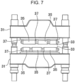
Fig. 7 illustrates, eachsegment roll 33 mounted on asegment frame 31 has divided rolls constituted by two to fourrolls 35 arranged in the axial direction, and an end portion of each of therolls 35 constituting the divided rolls is supported by a bearing portion provided in abearing box 37. Thesegment rolls 33 have a structure in which the plural pairs of divided rolls are arranged on the upper side and the lower side. - The
bearing boxes 37 for supporting therespective rolls 35 in thesegment rolls 33 and, inside each of thebearing boxes 37, the bearing portion, a seal portion, and a lubricating oil or a grease for lubrication are in contact with or adjacent to a cast piece during casting and are thus exposed to a high-temperature environment. Among the bearing portions, in particular, the bearing portions of thebearing boxes 37 disposed on the central side of eachsegment frame 31 have problems such as rotation failure due to carbonization of lubricant, breakage of the bearing portion, and hardening of the seal portion. - To address such problems,
Patent Literature 1 proposes a method of obtaining a cooling effect. In the method, plural grooves are formed in the outer periphery of a bearing box, cooling water is taken through an inflow hole at one end of each groove, and the other end of the groove is open to cause the cooling water that has flowed through the groove to flow down again from an outer surface of a lid of the bearing box. Thus, there are obtained the cooling effect of the inside of the bearing box due to the cooling water flowing through the groove and the cooling effect of the outside of the bearing box due to the evaporation heat when the cooling water flows down from the lid and is vaporized. - Moreover, Patent Literature 2 proposes a method for cooling a bearing box in a roller table for delivering a slab by blowing air from the outside.
- Furthermore,
Patent Literature 3 discloses that, in a roll segment device that guides a cast piece in a continuous casting machine, water is sprinkled on the roll segment based on the observation of a surface of the cast piece so as to prevent reduction in the accuracy of the thickness of the cast piece, which is caused by a roll-constituting member having heat due to the radiant heat of the cast piece. - Patent Literature 4 discloses, in a bearing box at the side facing to a cast slab, forming a semi-annular cooling water chamber by covering the cut groove by notching a part of the outer periphery at the side facing to the cast slab in the periphery direction with a semi-annular jacket plate arranged and the outer periphery of the jacket plate nearer to the center axis of the roll than the outer periphery of the above roll.
-
Patent Literature 5 discloses a roller and a roller arrangement for a continuous casting installation comprising two bearing blocks and the roller carried by the bearing blocks, wherein the roller has a rotationally symmetrical roller casing and wherein the roller bearing is arranged within the roller casing. - Patent Literature 6 discloses an arrangement for piping of cooling water for cooling the bearing of guide rolls.
-
- Patent Literature 1:
Japanese Unexamined Patent Application Publication No. 10-274247 - Patent Literature 2:
Japanese Unexamined Patent Application Publication No. 2003-290891 - Patent Literature 3:
Japanese Unexamined Patent Application Publication No. 2010-23061 - Patent Literature 4:
Japanese Unexamined Patent Application Publication No. 2004-148407 - Patent Literature 5:
US Patent Application Publication No. 2012/043047 - Patent Literature 6:
Japanese Unexamined Patent Application Publication H08 168859 A - However, the method disclosed in
Patent Literature 1 has the features of obtaining an external cooling effect due to the evaporation heat generated by the cooling water being discharged outside the bearing box. Thus, due to such features, there is concern about excessive cooling of the cast piece caused by the water that has been discharged outside being poured on the cast piece. - The method disclosed in Patent Literature 2 has problems where the cooling performed by using air exhibits a small heat removal effect, and, in addition, the bearing box is not cooled uniformly. Regarding, in particular, a bearing disposed on the central side of the segment, it is difficult to blow cooling air uniformly against a portion of the bearing that receives the radiant heat of the cast piece.
- Furthermore, although
Patent Literature 3 describes that the water is sprinkled on the roll segment, the method of sprinkling water is not described fully enough to be reproducible, and there is uncertainty about whether the bearing box can effectively be cooled. - As described above, none of
Patent Literatures 1 to 3 can achieve effective cooling of the bearing box. - Note that the commonest bearing box-cooling method of the related art is a method in which the bearing box is provided with a water-cooling jacket as with the disclosure of
Patent Literature 1 described above, in addition to the external cooling effect of the bearing box exhibited by using cast piece-cooling water that cools a cast piece. -
Fig. 8 illustrates such a common existing cooling structure of thebearing box 37 with a water-cooling jacket. InFig. 8 , 33 denotes a segment roll, 37 denotes a bearing box that supports a shaft of thesegment roll 33 so that the shaft can rotate, 39 denotes a bearing portion provided in thebearing box bearing portion 39 passes, and 47 denotes a lid member for forming thecooling water passage 45. - In the
bearing portion 39 in a continuous casting machine, the cooling of the related art has been performed by a water-cooling jacket being configured. Such a water-cooling jacket is configured by thecooling water passage 45 being formed in thebearing box 37 as described above and being covered with thelid member 47. However, regarding high-grade steel manufacturing in recent years, the casting method in which the cast piece-cooling water is reduced as much as possible in a curved zone positioned upstream of the casting to prevent a crack in a surface and a corner portion of a cast piece, has come to be conducted. Accordingly, the hitherto-obtained external cooling effect due to the cast piece-cooling water is decreased, and the thermal load applied to thebearing box 37 and theroll 35 increases. - Although the radiant heat from a
cast piece 49 affects, as the arrows inFig. 8 indicate, not only thebearing portion 39 but also theseal portion 41 provided adjacent to thebearing portion 39, the structure of the related art cannot cool theseal portion 41, and the thermal load applied to theseal portion 41 is large. - The present invention has been made to solve such a problem, and an object of the present invention is to provide a bearing box for a rotating roll that delivers high-temperature substance(s), the bearing box being capable of reducing a thermal load at a bearing portion and a seal portion provided adjacent to the bearing portion to effectively prevent rotation failure, breakage of the bearing portion, and hardening of the seal portion. Solution to Problem
- The solution to the above-described problem is as follows.
- [1] A bearing box for a rotating roll that delivers a high-temperature substance, the bearing box including a bearing portion and a seal portion provided adjacent to the bearing portion, the bearing box including: a first cooling liquid passage that is formed on the outer peripheral side of the bearing portion and through which a cooling liquid passes; and a second cooling liquid passage that is formed on the radially inner side relative to the first cooling liquid passage and on the outer peripheral side of the seal portion, the second cooling liquid passage communicating with the first cooling liquid passage to cause the cooling liquid to pass therethrough.
- [2] The bearing box for a rotating roll that delivers a high-temperature substance according to item [1], in which, in a section of the bearing box in the axial direction of the rotating roll, the total width of the first cooling liquid passage and the second cooling liquid passage is 1/2 or more of the width of the bearing box.
- [3] The bearing box for a rotating roll that delivers a high-temperature substance according to item [1] or [2], the bearing box including, a first jacket component that forms the first cooling liquid passage and a second jacket component that forms the second cooling liquid passage and has an annular shape.
- [4] The bearing box for a rotating roll that delivers a high-temperature substance according to item [3], in which, at the boundary between the first cooling liquid passage and the second cooling liquid passage, a plurality of fixing components for fixing the first jacket component and the second jacket component are provided at a predetermined interval.
- [5] The bearing box for a rotating roll that delivers a high-temperature substance according to item [4], in which each of the fixing components is fixed to a bottom surface of the first cooling liquid passage and has a protrusion protruding toward the side of the second cooling liquid passage, the first jacket component is fixed to a top surface of the fixing component, and the second jacket component is fixed to the protrusion of the fixing component.
- The bearing box for a rotating roll that delivers a high-temperature substance according to the present invention includes: the first cooling liquid passage that is formed on the outer peripheral side of the bearing portion and through which a cooling liquid passes; and the second cooling liquid passage that is formed on the radially inner side relative to the first cooling liquid passage and on the outer peripheral side of the seal portion, the second cooling liquid passage communicating with the first cooling liquid passage to cause the cooling liquid to pass therethrough, and it is thereby possible to cool not only the bearing portion but also the seal portion to reduce the thermal load at the seal portion. Thus, rotation failure, breakage of the bearing portion, and hardening of the seal portion can effectively be prevented.
-
- [
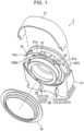
Fig. 1] Fig. 1 is an exploded perspective view of a bearing box according to the present embodiment. - [
Fig. 2] Fig. 2 is a front view of the bearing box according to the present embodiment. - [
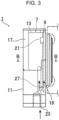
Fig. 3] Fig. 3 is a side view of the bearing box according to the present embodiment. - [
Fig. 4] Fig. 4 is a back view of the bearing box according to the present embodiment. - [
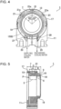
Fig. 5] Fig. 5 is a sectional view taken along line A-A inFig. 2 . - [
Fig. 6] Fig. 6 is a sectional view taken along line B-B inFig. 3 . - [
Fig. 7] Fig. 7 illustrates a segment frame of a continuous casting machine. - [
Fig. 8] Fig. 8 illustrates a bearing box of an example of the related art provided at an end portion of a segment roll. - Regarding a bearing box for a rotating roll that delivers a high-temperature substance according to the present invention (hereinafter, referred to as simply "bearing box"), a
bearing box 1 for a segment roll mounted on a segment frame of a continuous casting machine will be described, as an example, based onFigs. 1 to 6 . Note that a cooling liquid passage that is a distinctive portion of the present invention is mainly illustrated inFigs. 1 to 6 , while abearing portion 3 and aseal portion 5 are illustrated only by phantom lines, that is, chain double-dashed lines inFig. 5 and the illustration thereof is omitted; however, the basic structures of thebearing portion 3 and theseal portion 5 are similar to those inFig. 8 . - As
Figs. 1 to 6 illustrate, thebearing box 1 according to the present invention includes the bearingportion 3 and theseal portion 5 provided adjacent to the bearing portion 3 (refer toFig. 5 ), and thebearing box 1 includes a firstcooling liquid passage 7 that is formed on the outer peripheral side of the bearingportion 3 and through which a cooling liquid passes and a secondcooling liquid passage 9 that is formed on the radially inner side relative to the first coolingliquid passage 7 and on the outer peripheral side of theseal portion 5 and through which the cooling liquid passes. - The first
cooling liquid passage 7 and the secondcooling liquid passage 9 are formed by afirst jacket component 17 and asecond jacket component 19 being mounted respectively on a first cooling liquid passagebottom portion 13 and a second cooling liquid passagebottom portion 15 formed in amain body 11 of thebearing box 1, so as to cover the respective cooling liquid passage bottom portions. - As
Fig. 1 illustrates, thefirst jacket component 17 is constituted by a plate member having a semi-circular arc shape, and thesecond jacket component 19 is constituted by an annular member. -
Plural fixing components 21 for fixing thefirst jacket component 17 and thesecond jacket component 19 are provided, at a predetermined interval, on a portion of the first cooling liquid passagebottom portion 13 positioned on the secondcooling liquid passage 9 side. - As
Fig. 1 andFig. 5 illustrate, each of the fixingcomponents 21 has aprotrusion 21a protruding toward the secondcooling liquid passage 9 side, thefirst jacket component 17 is fixed to a top surface of each fixingcomponent 21 by welding, and thesecond jacket component 19 is fixed to eachprotrusion 21a by welding. - A water-cooling jacket structure is configured by the
first jacket component 17 and thesecond jacket component 19 being fixed by welding to form a sealed structure. - The first
cooling liquid passage 7 and the secondcooling liquid passage 9, which are configured as described above, communicate with one another, and, asFig. 1 illustrates, the cooling liquid flowing in the first coolingliquid passage 7 and the cooling liquid flowing in the secondcooling liquid passage 9 can mutually flow back and forth between both the cooling liquid passages. - Thus, by the first cooling
liquid passage 7 and the secondcooling liquid passage 9 communicating with one another, the cooling liquid flows not only in one cooling liquid passage having small resistance (the first coolingliquid passage 7 in the present embodiment), but the cooling liquid can be caused to flow all around both the cooling liquid passages without stagnating. - A cooling liquid-supplying
portion 23 and a cooling liquid-dischargingportion 25 are provided in a lower portion of themain body 11 of thebearing box 1. - The cooling liquid-supplying
portion 23 is constituted by apassage 27 extending upward from the lower portion and bifurcating into two passages communicating respectively with the first coolingliquid passage 7 and the secondcooling liquid passage 9. - In addition, as with the cooling liquid-supplying
portion 23, the cooling liquid-dischargingportion 25 is also constituted by apassage 29 bifurcating into two passages, the twopassages 29 communicating respectively with the first coolingliquid passage 7 and the secondcooling liquid passage 9. - In a section of the
bearing box 1 in the axial direction of the rotating roll, that is, the section (refer toFig. 5 ) taken along line A-A inFig. 2 , the total of a width A of the first coolingliquid passage 7 and a width B of the second cooling liquid passage 9 (A + B) is set to 1/2 or more of a width C of thebearing box 1. The reasons for such setting are as follows. - The problem to be solved with the present invention is how to prevent the inability of a bearing to rotate due to an oxidized lubricating oil stain caused by the temperature of the bearing
portion 3 being raised by the bearingportion 3 and theseal portion 5 being heated by the radiant heat from a cast piece. - Most of the radiant heat from the cast piece is infrared radiation, and the wavelength of such infrared radiation is extremely small with respect to the members constituting the bearing
portion 3 and theseal portion 5; thus, the diffraction effect on, for example, an obstacle is not exhibited. Consequently, when viewing from the position of each portion of thebearing box 1 toward a cast piece and if the cast piece turning bright red can be seen even in small part, the portion of thebearing box 1 at such a position is heated by the infrared radiation of the cast piece. - Thus, in the present embodiment, the heat resistance of the bearing
portion 3 is improved by increasing the water-cooling coverage with respect to the infrared radiation emitted from a high-temperature substance, that is, setting the water-cooling coverage to 1/2 or more. - The
bearing box 1, according to the present embodiment, configured as described above includes the first coolingliquid passage 7 and the secondcooling liquid passage 9 that is formed on the radially inner side relative to the first coolingliquid passage 7 and on the outer peripheral side of theseal portion 5, the secondcooling liquid passage 9 communicating with the first coolingliquid passage 7 to cause the cooling liquid to pass therethrough, and the water-cooling jacket thereby completely blocks the radiant heat from the cast piece to suppress not only an increase in the temperature of the bearingportion 3 but also an increase in the temperature of theseal portion 5. Thus, carbonization of a bearing lubricant and hardening of a seal can be prevented. - That is, the thermal flux moving toward the bearing
portion 3 from the surface of thebearing box 1 at which the radiant heat generated from the cast piece arrives can mainly be reduced by the cooling liquid flowing in the first coolingliquid passage 7, and the thermal flux moving toward the bearingportion 3 and theseal portion 5 of a neck of the rotating roll from the surface of thebearing box 1 at which the radiant heat generated from the cast piece arrives can be reduced by the cooling liquid flowing in the secondcooling liquid passage 9. Thus, the thermal load is effectively reduced. - Note that, although the cooling liquid-supplying
portion 23 and the cooling liquid-dischargingportion 25 are provided in the lower portion of themain body 11 in the example illustrated inFigs. 1 to 6 , the positions at which the cooling liquid-supplyingportion 23 and the cooling liquid-dischargingportion 25 are provided are not particularly limited, and the cooling liquid-supplyingportion 23 and the cooling liquid-dischargingportion 25 may be provided, for example, at a side of themain body 11. - In addition, although the
bearing box 1 for the segment roll mounted on the segment frame of the continuous casting machine is described as an example in the above-described embodiment, the bearing box according to the present invention is not limited to thebearing box 1 for the segment roll and is widely applicable to bearing boxes for a rotating roll that delivers a high-temperature substance. Example - A test was conducted to verify the effects of the present invention. In the test, a bearing box for a cast piece-supporting roll (guide roll) of a steel-slab continuous casting machine was used, and the bearing box was cooled by cooling water. Hereinafter, the test will be described.
- The test-target bearing box is a bearing box for the cast piece-supporting roll that supports a cast piece having a surface temperature of 700 to 900°C, and a bearing (rolling-element bearing) having an outside diameter of 170 mm, an inside diameter of 110 mm, and a width of 43 mm is mounted in the bearing box.
- In the test, the
bearing box 1, according to the present invention, illustrated inFigs. 1 to 6 and thebearing box 37 illustrated inFig. 8 for comparison were installed, and the temperatures of thebearing box 1 and thebearing box 37 during continuous casting were measured and compared with one another. - With respect to the
bearing box 1, according to the present invention, illustrated inFigs. 1 to 6 (hereinafter, also referred to as "example of the present invention") and thebearing box 37 illustrated inFig. 8 for comparison (hereinafter, also referred as "example of the related art"), cooling water was taken into each bearing box at 15L per minute, and thebearing box 1 and thebearing box 37 were cooled. Regarding both thebearing box 1 according to the present invention and thebearing box 37 as the example of the related art, the cooling water after cooling thebearing box 1 and thebearing box 37 was then caused to run down along the outer peripheries of therespective bearing boxes - The position of an end portion of each of the bearing
portions respective seal portions Fig. 5 andFig. 8 , and the temperature at each position P during a continuous casting operation over a one-day period was measured by using a sheathed thermocouple. As a result, in the example of the present invention, during the continuous casting, the temperature of theseal portion 5 was lower than the temperature of theseal portion 41 of the example of the related art by 20 to 40°C, and it was thus verified that the influence of the radiant heat from the cast piece on theseal portion 5 was able to be reduced. - In the example of the related art, the
seal portion 41 is not covered with thelid member 47, whereas, in the example of present invention, theseal portion 5 is also covered with thesecond jacket component 19. Thus, as a result of obtaining the temperatures of these portions by performing temperature analysis, it was verified that the temperature of theseal portion 5 of the example of present invention is also decreased compared with the temperature of the seal portion of the example of the related art. -
- 1
- bearing box
- 3
- bearing portion
- 5
- seal portion
- 7
- first cooling liquid passage
- 9
- second cooling liquid passage
- 11
- main body
- 13
- first cooling liquid passage bottom portion
- 15
- second cooling liquid passage bottom portion
- 17
- first jacket component
- 19
- second jacket component
- 21
- fixing component
- 21a
- protrusion
- 23
- cooling liquid-supplying portion
- 25
- cooling liquid-discharging portion
- 27
- passage (cooling liquid-supplying portion)
- 29
- passage (cooling liquid-discharging portion)
-
- 31
- segment frame
- 33
- segment roll
- 35
- roll
- 37
- bearing box
- 39
- bearing portion
- 41
- seal portion
- 43
- retainer
- 45
- cooling water passage
- 47
- lid member
- 49
- cast piece
Claims (5)
- A bearing box (1) for a rotating roll that delivers a high-temperature substance, the bearing box (1) including a bearing portion (3) and a seal portion (5) provided adjacent to the bearing portion (3), the bearing box (1) comprising:a first cooling liquid passage (7) that is formed on an outer peripheral side of the bearing portion (3) and through which a cooling liquid passes; anda second cooling liquid passage (9) that is formed on a radially inner side relative to the first cooling liquid passage (7) and on an outer peripheral side of the seal portion (5), the second cooling liquid passage (9) communicating with the first cooling liquid passage (7) to cause the cooling liquid to pass therethrough.
- The bearing box (1) for a rotating roll that delivers a high-temperature substance according to Claim 1, wherein, in a section of the bearing box (1) in an axial direction of the rotating roll, a total width of the first cooling liquid passage (7) and the second cooling liquid passage (9) is 1/2 or more of a width of the bearing box (1).
- The bearing box (1) for a rotating roll that delivers a high-temperature substance according to Claim 1 or 2, the bearing box (1) comprising: a first jacket component (17) that forms the first cooling liquid passage (7); and a second jacket component (19) that forms the second cooling liquid passage (9) and has an annular shape.
- The bearing box (1) for a rotating roll that delivers a high-temperature substance according to Claim 3, wherein, at a boundary between the first cooling liquid passage (7) and the second cooling liquid passage (9), a plurality of fixing components (21) for fixing the first jacket component (17) and the second jacket component (19) are provided at a predetermined interval.
- The bearing box (1) for a rotating roll that delivers a high-temperature substance according to Claim 4, wherein each of the fixing components (21) is fixed to a bottom surface of the first cooling liquid passage (7) and has a protrusion (21a) protruding toward a side of the second cooling liquid passage (9), the first jacket component (17) is fixed to a top surface of the fixing component (21), and the second jacket component (19) is fixed to the protrusion of the fixing component (21).
Applications Claiming Priority (2)
| Application Number | Priority Date | Filing Date | Title |
|---|---|---|---|
| JP2019168952A JP7311370B2 (en) | 2019-09-18 | 2019-09-18 | Bearing boxes for rotary rolls that carry high-temperature objects |
| PCT/JP2020/035402 WO2021054426A1 (en) | 2019-09-18 | 2020-09-18 | Bearing box for rotating roll that carries high-temperature object |
Publications (3)
| Publication Number | Publication Date |
|---|---|
| EP4005698A1 EP4005698A1 (en) | 2022-06-01 |
| EP4005698A4 EP4005698A4 (en) | 2022-08-31 |
| EP4005698B1 true EP4005698B1 (en) | 2023-08-23 |
Family
ID=74877284
Family Applications (1)
| Application Number | Title | Priority Date | Filing Date |
|---|---|---|---|
| EP20866469.8A Active EP4005698B1 (en) | 2019-09-18 | 2020-09-18 | Bearing box for rotating roll that carries high-temperature object |
Country Status (7)
| Country | Link |
|---|---|
| US (1) | US11933363B2 (en) |
| EP (1) | EP4005698B1 (en) |
| JP (1) | JP7311370B2 (en) |
| KR (1) | KR102644414B1 (en) |
| CN (1) | CN114375232B (en) |
| BR (1) | BR112022005050A2 (en) |
| WO (1) | WO2021054426A1 (en) |
Families Citing this family (1)
| Publication number | Priority date | Publication date | Assignee | Title |
|---|---|---|---|---|
| CN117182016A (en) * | 2022-05-31 | 2023-12-08 | 斯凯孚公司 | Support unit and continuous casting guide roll assembly comprising same |
Citations (3)
| Publication number | Priority date | Publication date | Assignee | Title |
|---|---|---|---|---|
| JP2004148407A (en) | 2003-11-28 | 2004-05-27 | Jfe Steel Kk | Device for sealing bearing for roll in continuous caster, sealing method and continuous caster |
| JP2006035236A (en) | 2004-07-22 | 2006-02-09 | Kobe Steel Ltd | Cast slab guide apparatus for continuous casting equipment |
| DE102016224761A1 (en) | 2015-12-11 | 2017-06-14 | Sms Group Gmbh | Bearing for receiving a bearing for a roll |
Family Cites Families (24)
| Publication number | Priority date | Publication date | Assignee | Title |
|---|---|---|---|---|
| JPS5482327A (en) * | 1977-12-14 | 1979-06-30 | Kawasaki Steel Co | Intermediate bearing device for devided casttstrippguidinggroller in continuous casting apparatus |
| DE3319537A1 (en) * | 1983-05-28 | 1984-11-29 | Klein, Schanzlin & Becker Ag, 6710 Frankenthal | DEVICE FOR THE OIL SUPPLY OF A HIGHLY HEAT-LOADED SHAFT BEARING |
| DE4114842C2 (en) * | 1991-05-07 | 1995-08-03 | Skf Gmbh | Rolling bearing provided with a sealing arrangement |
| DE4207042C1 (en) | 1992-03-02 | 1993-09-16 | Mannesmann Ag, 40213 Duesseldorf, De | Coolant coupling for roll device - with good sealant properties provided by elastic socket feeding coolant into roll bore |
| RU2038187C1 (en) | 1992-12-14 | 1995-06-27 | Производственное объединение "Южуралмаш" | Device for continuous casting of metal |
| JP3083720B2 (en) | 1994-12-16 | 2000-09-04 | 住友重機械工業株式会社 | Roll segment cooling device in continuous casting equipment |
| US5915843A (en) * | 1996-07-12 | 1999-06-29 | The Torrington Company | Fluid-cooled bearing housing |
| JPH10274247A (en) * | 1997-03-27 | 1998-10-13 | Nisshin Steel Co Ltd | Bearing box and foot roll segment |
| JP2003290891A (en) | 2002-04-03 | 2003-10-14 | Jfe Steel Kk | Bearing device for table roll in continuous caster and method for cooling bearing |
| JP2004011766A (en) * | 2002-06-06 | 2004-01-15 | Nsk Ltd | Bearing device |
| DE10302474A1 (en) | 2003-01-23 | 2004-08-05 | Sms Demag Ag | Cooling of rolls in continuous casting plants |
| DE102005052067A1 (en) | 2005-10-28 | 2007-05-03 | Georg Springmann Industrie- Und Bergbautechnik Gmbh | Device for coupling a coolant supply to a roller |
| JP5217719B2 (en) | 2008-07-16 | 2013-06-19 | 新日鐵住金株式会社 | Roll segment equipment in continuous casting equipment |
| JP5659521B2 (en) * | 2009-04-06 | 2015-01-28 | 株式会社ジェイテクト | Rolling bearing device |
| MX2011004690A (en) | 2009-09-04 | 2011-07-29 | Sms Concast Ag | Roll and roll arrangement for a continuous casting installation. |
| CN201823915U (en) | 2010-10-27 | 2011-05-11 | 威尔机械江苏有限公司 | Bearing seat of continuous casting machine |
| US9343646B2 (en) * | 2011-10-06 | 2016-05-17 | Aktiebolaget Skf | Thermo-electric power harvesting bearing configuration |
| JP2013103254A (en) | 2011-11-15 | 2013-05-30 | Sumitomo Heavy Industries Techno-Fort Co Ltd | Guide roll cooling device of continuous casting facility |
| AT513431B1 (en) | 2012-09-28 | 2015-10-15 | Primetals Technologies Austria GmbH | Chilled, multi-layered strand guide roller |
| AT514625B1 (en) | 2013-07-24 | 2018-07-15 | Primetals Technologies Austria GmbH | Chilled strand guide roller |
| CN203868150U (en) * | 2014-03-25 | 2014-10-08 | 新疆金特钢铁股份有限公司 | Water cooling type bearing block for bend pulley of belt conveyor |
| CN206206423U (en) | 2016-11-21 | 2017-05-31 | 南京磁谷科技有限公司 | A kind of bearing cooling structure |
| CN207154718U (en) | 2017-09-26 | 2018-03-30 | 黄石市火炬科技实业有限责任公司 | A kind of cooling water circulating device for continuous casting roller group |
| EP4159343A1 (en) * | 2021-09-29 | 2023-04-05 | Primetals Technologies Austria GmbH | Pedestal bearing and production plant with such a pedestal bearing |
-
2019
- 2019-09-18 JP JP2019168952A patent/JP7311370B2/en active Active
-
2020
- 2020-09-18 US US17/761,775 patent/US11933363B2/en active Active
- 2020-09-18 KR KR1020227008493A patent/KR102644414B1/en active IP Right Grant
- 2020-09-18 BR BR112022005050A patent/BR112022005050A2/en unknown
- 2020-09-18 CN CN202080064192.6A patent/CN114375232B/en active Active
- 2020-09-18 EP EP20866469.8A patent/EP4005698B1/en active Active
- 2020-09-18 WO PCT/JP2020/035402 patent/WO2021054426A1/en unknown
Patent Citations (3)
| Publication number | Priority date | Publication date | Assignee | Title |
|---|---|---|---|---|
| JP2004148407A (en) | 2003-11-28 | 2004-05-27 | Jfe Steel Kk | Device for sealing bearing for roll in continuous caster, sealing method and continuous caster |
| JP2006035236A (en) | 2004-07-22 | 2006-02-09 | Kobe Steel Ltd | Cast slab guide apparatus for continuous casting equipment |
| DE102016224761A1 (en) | 2015-12-11 | 2017-06-14 | Sms Group Gmbh | Bearing for receiving a bearing for a roll |
Also Published As
| Publication number | Publication date |
|---|---|
| US11933363B2 (en) | 2024-03-19 |
| JP2021045765A (en) | 2021-03-25 |
| EP4005698A1 (en) | 2022-06-01 |
| KR102644414B1 (en) | 2024-03-06 |
| US20220373034A1 (en) | 2022-11-24 |
| WO2021054426A1 (en) | 2021-03-25 |
| CN114375232B (en) | 2024-04-05 |
| EP4005698A4 (en) | 2022-08-31 |
| JP7311370B2 (en) | 2023-07-19 |
| BR112022005050A2 (en) | 2022-06-14 |
| KR20220044595A (en) | 2022-04-08 |
| CN114375232A (en) | 2022-04-19 |
Similar Documents
| Publication | Publication Date | Title |
|---|---|---|
| EP4005698B1 (en) | Bearing box for rotating roll that carries high-temperature object | |
| KR101377090B1 (en) | Twin roll caster and equipment and method for operating the same | |
| RU2553139C2 (en) | Distributor, roller line and device for continuous casting | |
| US7594535B2 (en) | Twin roll caster, and equipment and method for operating the same | |
| EP4006369B1 (en) | Bearing box for rotating roll, cooling method for rotating roll bearing box, steel continuous casting machine, and steel continuous casting method | |
| RU2553140C2 (en) | Distributor, roller line and device for continuous casting | |
| EP2682202B1 (en) | Roll line and continuous casting apparatus | |
| RU2805517C2 (en) | Bearing housing for a rotating roller which supplies high temperature substance or substances | |
| JP6835016B2 (en) | Bearing box and bearing box cooling method | |
| RU2788541C1 (en) | Bearing housing for rotating roll, method for cooling bearing housing for rotating roll, machine for continuous casting of steel blanks and method for continuous casting of steel blanks | |
| EP2680990B1 (en) | Method for extending the service life of a roll line | |
| RU2022107189A (en) | BEARING HOUSING FOR A ROTATING ROLLER WHICH SUPPLY HIGH TEMPERATURE SUBSTANCE OR SUBSTANCES | |
| KR100489015B1 (en) | A cooling roll for twin roll-strip caster | |
| KR0123098Y1 (en) | Cooling roll for double roll wafer | |
| JP2013068279A (en) | Roller bearing device | |
| JPH03106544A (en) | Method for supplying lubricant in continuous casting mold | |
| JP2013185161A (en) | Temperature equalizing roller |
Legal Events
| Date | Code | Title | Description |
|---|---|---|---|
| STAA | Information on the status of an ep patent application or granted ep patent |
Free format text: STATUS: THE INTERNATIONAL PUBLICATION HAS BEEN MADE |
|
| PUAI | Public reference made under article 153(3) epc to a published international application that has entered the european phase |
Free format text: ORIGINAL CODE: 0009012 |
|
| STAA | Information on the status of an ep patent application or granted ep patent |
Free format text: STATUS: REQUEST FOR EXAMINATION WAS MADE |
|
| 17P | Request for examination filed |
Effective date: 20220225 |
|
| AK | Designated contracting states |
Kind code of ref document: A1 Designated state(s): AL AT BE BG CH CY CZ DE DK EE ES FI FR GB GR HR HU IE IS IT LI LT LU LV MC MK MT NL NO PL PT RO RS SE SI SK SM TR |
|
| A4 | Supplementary search report drawn up and despatched |
Effective date: 20220802 |
|
| RIC1 | Information provided on ipc code assigned before grant |
Ipc: F16J 15/16 20060101ALI20220727BHEP Ipc: F16C 35/04 20060101ALI20220727BHEP Ipc: F16C 37/00 20060101ALI20220727BHEP Ipc: F16C 13/02 20060101ALI20220727BHEP Ipc: B22D 11/128 20060101AFI20220727BHEP |
|
| DAV | Request for validation of the european patent (deleted) | ||
| DAX | Request for extension of the european patent (deleted) | ||
| RIC1 | Information provided on ipc code assigned before grant |
Ipc: F16C 37/00 20060101ALN20230220BHEP Ipc: F16J 15/324 20160101ALI20230220BHEP Ipc: F16J 15/16 20060101ALI20230220BHEP Ipc: F16C 35/04 20060101ALI20230220BHEP Ipc: F16C 13/02 20060101ALI20230220BHEP Ipc: B22D 11/128 20060101AFI20230220BHEP |
|
| GRAP | Despatch of communication of intention to grant a patent |
Free format text: ORIGINAL CODE: EPIDOSNIGR1 |
|
| STAA | Information on the status of an ep patent application or granted ep patent |
Free format text: STATUS: GRANT OF PATENT IS INTENDED |
|
| RIC1 | Information provided on ipc code assigned before grant |
Ipc: F16C 37/00 20060101ALN20230322BHEP Ipc: F16J 15/324 20160101ALI20230322BHEP Ipc: F16J 15/16 20060101ALI20230322BHEP Ipc: F16C 35/04 20060101ALI20230322BHEP Ipc: F16C 13/02 20060101ALI20230322BHEP Ipc: B22D 11/128 20060101AFI20230322BHEP |
|
| INTG | Intention to grant announced |
Effective date: 20230426 |
|
| RIN1 | Information on inventor provided before grant (corrected) |
Inventor name: OHARA, NORIAKI Inventor name: FUJII, AKITAKA Inventor name: ITO, SHINYA Inventor name: ISOZAKI, KENJI |
|
| GRAS | Grant fee paid |
Free format text: ORIGINAL CODE: EPIDOSNIGR3 |
|
| GRAA | (expected) grant |
Free format text: ORIGINAL CODE: 0009210 |
|
| STAA | Information on the status of an ep patent application or granted ep patent |
Free format text: STATUS: THE PATENT HAS BEEN GRANTED |
|
| AK | Designated contracting states |
Kind code of ref document: B1 Designated state(s): AL AT BE BG CH CY CZ DE DK EE ES FI FR GB GR HR HU IE IS IT LI LT LU LV MC MK MT NL NO PL PT RO RS SE SI SK SM TR |
|
| REG | Reference to a national code |
Ref country code: GB Ref legal event code: FG4D |
|
| REG | Reference to a national code |
Ref country code: CH Ref legal event code: EP |
|
| REG | Reference to a national code |
Ref country code: IE Ref legal event code: FG4D |
|
| REG | Reference to a national code |
Ref country code: DE Ref legal event code: R096 Ref document number: 602020016424 Country of ref document: DE |
|
| PGFP | Annual fee paid to national office [announced via postgrant information from national office to epo] |
Ref country code: FR Payment date: 20230915 Year of fee payment: 4 |
|
| REG | Reference to a national code |
Ref country code: LT Ref legal event code: MG9D |
|
| REG | Reference to a national code |
Ref country code: NL Ref legal event code: MP Effective date: 20230823 |
|
| PG25 | Lapsed in a contracting state [announced via postgrant information from national office to epo] |
Ref country code: GR Free format text: LAPSE BECAUSE OF FAILURE TO SUBMIT A TRANSLATION OF THE DESCRIPTION OR TO PAY THE FEE WITHIN THE PRESCRIBED TIME-LIMIT Effective date: 20231124 |
|
| PG25 | Lapsed in a contracting state [announced via postgrant information from national office to epo] |
Ref country code: IS Free format text: LAPSE BECAUSE OF FAILURE TO SUBMIT A TRANSLATION OF THE DESCRIPTION OR TO PAY THE FEE WITHIN THE PRESCRIBED TIME-LIMIT Effective date: 20231223 |
|
| PG25 | Lapsed in a contracting state [announced via postgrant information from national office to epo] |
Ref country code: SE Free format text: LAPSE BECAUSE OF FAILURE TO SUBMIT A TRANSLATION OF THE DESCRIPTION OR TO PAY THE FEE WITHIN THE PRESCRIBED TIME-LIMIT Effective date: 20230823 Ref country code: RS Free format text: LAPSE BECAUSE OF FAILURE TO SUBMIT A TRANSLATION OF THE DESCRIPTION OR TO PAY THE FEE WITHIN THE PRESCRIBED TIME-LIMIT Effective date: 20230823 Ref country code: PT Free format text: LAPSE BECAUSE OF FAILURE TO SUBMIT A TRANSLATION OF THE DESCRIPTION OR TO PAY THE FEE WITHIN THE PRESCRIBED TIME-LIMIT Effective date: 20231226 Ref country code: NO Free format text: LAPSE BECAUSE OF FAILURE TO SUBMIT A TRANSLATION OF THE DESCRIPTION OR TO PAY THE FEE WITHIN THE PRESCRIBED TIME-LIMIT Effective date: 20231123 Ref country code: NL Free format text: LAPSE BECAUSE OF FAILURE TO SUBMIT A TRANSLATION OF THE DESCRIPTION OR TO PAY THE FEE WITHIN THE PRESCRIBED TIME-LIMIT Effective date: 20230823 Ref country code: LV Free format text: LAPSE BECAUSE OF FAILURE TO SUBMIT A TRANSLATION OF THE DESCRIPTION OR TO PAY THE FEE WITHIN THE PRESCRIBED TIME-LIMIT Effective date: 20230823 Ref country code: LT Free format text: LAPSE BECAUSE OF FAILURE TO SUBMIT A TRANSLATION OF THE DESCRIPTION OR TO PAY THE FEE WITHIN THE PRESCRIBED TIME-LIMIT Effective date: 20230823 Ref country code: IS Free format text: LAPSE BECAUSE OF FAILURE TO SUBMIT A TRANSLATION OF THE DESCRIPTION OR TO PAY THE FEE WITHIN THE PRESCRIBED TIME-LIMIT Effective date: 20231223 Ref country code: HR Free format text: LAPSE BECAUSE OF FAILURE TO SUBMIT A TRANSLATION OF THE DESCRIPTION OR TO PAY THE FEE WITHIN THE PRESCRIBED TIME-LIMIT Effective date: 20230823 Ref country code: GR Free format text: LAPSE BECAUSE OF FAILURE TO SUBMIT A TRANSLATION OF THE DESCRIPTION OR TO PAY THE FEE WITHIN THE PRESCRIBED TIME-LIMIT Effective date: 20231124 Ref country code: FI Free format text: LAPSE BECAUSE OF FAILURE TO SUBMIT A TRANSLATION OF THE DESCRIPTION OR TO PAY THE FEE WITHIN THE PRESCRIBED TIME-LIMIT Effective date: 20230823 |
|
| PGFP | Annual fee paid to national office [announced via postgrant information from national office to epo] |
Ref country code: TR Payment date: 20231106 Year of fee payment: 4 Ref country code: IT Payment date: 20230930 Year of fee payment: 4 Ref country code: DE Payment date: 20231020 Year of fee payment: 4 |
|
| REG | Reference to a national code |
Ref country code: AT Ref legal event code: UEP Ref document number: 1601985 Country of ref document: AT Kind code of ref document: T Effective date: 20230823 |
|
| PG25 | Lapsed in a contracting state [announced via postgrant information from national office to epo] |
Ref country code: PL Free format text: LAPSE BECAUSE OF FAILURE TO SUBMIT A TRANSLATION OF THE DESCRIPTION OR TO PAY THE FEE WITHIN THE PRESCRIBED TIME-LIMIT Effective date: 20230823 |
|
| PG25 | Lapsed in a contracting state [announced via postgrant information from national office to epo] |
Ref country code: ES Free format text: LAPSE BECAUSE OF FAILURE TO SUBMIT A TRANSLATION OF THE DESCRIPTION OR TO PAY THE FEE WITHIN THE PRESCRIBED TIME-LIMIT Effective date: 20230823 |
|
| PG25 | Lapsed in a contracting state [announced via postgrant information from national office to epo] |
Ref country code: SM Free format text: LAPSE BECAUSE OF FAILURE TO SUBMIT A TRANSLATION OF THE DESCRIPTION OR TO PAY THE FEE WITHIN THE PRESCRIBED TIME-LIMIT Effective date: 20230823 Ref country code: RO Free format text: LAPSE BECAUSE OF FAILURE TO SUBMIT A TRANSLATION OF THE DESCRIPTION OR TO PAY THE FEE WITHIN THE PRESCRIBED TIME-LIMIT Effective date: 20230823 Ref country code: ES Free format text: LAPSE BECAUSE OF FAILURE TO SUBMIT A TRANSLATION OF THE DESCRIPTION OR TO PAY THE FEE WITHIN THE PRESCRIBED TIME-LIMIT Effective date: 20230823 Ref country code: EE Free format text: LAPSE BECAUSE OF FAILURE TO SUBMIT A TRANSLATION OF THE DESCRIPTION OR TO PAY THE FEE WITHIN THE PRESCRIBED TIME-LIMIT Effective date: 20230823 Ref country code: DK Free format text: LAPSE BECAUSE OF FAILURE TO SUBMIT A TRANSLATION OF THE DESCRIPTION OR TO PAY THE FEE WITHIN THE PRESCRIBED TIME-LIMIT Effective date: 20230823 Ref country code: CZ Free format text: LAPSE BECAUSE OF FAILURE TO SUBMIT A TRANSLATION OF THE DESCRIPTION OR TO PAY THE FEE WITHIN THE PRESCRIBED TIME-LIMIT Effective date: 20230823 Ref country code: SK Free format text: LAPSE BECAUSE OF FAILURE TO SUBMIT A TRANSLATION OF THE DESCRIPTION OR TO PAY THE FEE WITHIN THE PRESCRIBED TIME-LIMIT Effective date: 20230823 |
|
| REG | Reference to a national code |
Ref country code: CH Ref legal event code: PL |
|
| PG25 | Lapsed in a contracting state [announced via postgrant information from national office to epo] |
Ref country code: LU Free format text: LAPSE BECAUSE OF NON-PAYMENT OF DUE FEES Effective date: 20230918 |
|
| PLBI | Opposition filed |
Free format text: ORIGINAL CODE: 0009260 |