EP4005698B1 - Lagergehäuse für rotierende walze, die ein hochtemperaturobjekt trägt - Google Patents
Lagergehäuse für rotierende walze, die ein hochtemperaturobjekt trägt Download PDFInfo
- Publication number
- EP4005698B1 EP4005698B1 EP20866469.8A EP20866469A EP4005698B1 EP 4005698 B1 EP4005698 B1 EP 4005698B1 EP 20866469 A EP20866469 A EP 20866469A EP 4005698 B1 EP4005698 B1 EP 4005698B1
- Authority
- EP
- European Patent Office
- Prior art keywords
- cooling liquid
- bearing box
- liquid passage
- bearing
- cooling
- Prior art date
- Legal status (The legal status is an assumption and is not a legal conclusion. Google has not performed a legal analysis and makes no representation as to the accuracy of the status listed.)
- Active
Links
Images


Classifications
-
- F—MECHANICAL ENGINEERING; LIGHTING; HEATING; WEAPONS; BLASTING
- F16—ENGINEERING ELEMENTS AND UNITS; GENERAL MEASURES FOR PRODUCING AND MAINTAINING EFFECTIVE FUNCTIONING OF MACHINES OR INSTALLATIONS; THERMAL INSULATION IN GENERAL
- F16C—SHAFTS; FLEXIBLE SHAFTS; ELEMENTS OR CRANKSHAFT MECHANISMS; ROTARY BODIES OTHER THAN GEARING ELEMENTS; BEARINGS
- F16C37/00—Cooling of bearings
- F16C37/007—Cooling of bearings of rolling bearings
-
- B—PERFORMING OPERATIONS; TRANSPORTING
- B22—CASTING; POWDER METALLURGY
- B22D—CASTING OF METALS; CASTING OF OTHER SUBSTANCES BY THE SAME PROCESSES OR DEVICES
- B22D11/00—Continuous casting of metals, i.e. casting in indefinite lengths
- B22D11/12—Accessories for subsequent treating or working cast stock in situ
- B22D11/128—Accessories for subsequent treating or working cast stock in situ for removing
- B22D11/1287—Rolls; Lubricating, cooling or heating rolls while in use
-
- B—PERFORMING OPERATIONS; TRANSPORTING
- B21—MECHANICAL METAL-WORKING WITHOUT ESSENTIALLY REMOVING MATERIAL; PUNCHING METAL
- B21B—ROLLING OF METAL
- B21B31/00—Rolling stand structures; Mounting, adjusting, or interchanging rolls, roll mountings, or stand frames
- B21B31/07—Adaptation of roll neck bearings
- B21B31/076—Cooling; Lubricating roller bearings
-
- F—MECHANICAL ENGINEERING; LIGHTING; HEATING; WEAPONS; BLASTING
- F16—ENGINEERING ELEMENTS AND UNITS; GENERAL MEASURES FOR PRODUCING AND MAINTAINING EFFECTIVE FUNCTIONING OF MACHINES OR INSTALLATIONS; THERMAL INSULATION IN GENERAL
- F16C—SHAFTS; FLEXIBLE SHAFTS; ELEMENTS OR CRANKSHAFT MECHANISMS; ROTARY BODIES OTHER THAN GEARING ELEMENTS; BEARINGS
- F16C13/00—Rolls, drums, discs, or the like; Bearings or mountings therefor
- F16C13/02—Bearings
-
- F—MECHANICAL ENGINEERING; LIGHTING; HEATING; WEAPONS; BLASTING
- F16—ENGINEERING ELEMENTS AND UNITS; GENERAL MEASURES FOR PRODUCING AND MAINTAINING EFFECTIVE FUNCTIONING OF MACHINES OR INSTALLATIONS; THERMAL INSULATION IN GENERAL
- F16C—SHAFTS; FLEXIBLE SHAFTS; ELEMENTS OR CRANKSHAFT MECHANISMS; ROTARY BODIES OTHER THAN GEARING ELEMENTS; BEARINGS
- F16C35/00—Rigid support of bearing units; Housings, e.g. caps, covers
- F16C35/04—Rigid support of bearing units; Housings, e.g. caps, covers in the case of ball or roller bearings
- F16C35/042—Housings for rolling element bearings for rotary movement
- F16C35/047—Housings for rolling element bearings for rotary movement with a base plate substantially parallel to the axis of rotation, e.g. horizontally mounted pillow blocks
-
- F—MECHANICAL ENGINEERING; LIGHTING; HEATING; WEAPONS; BLASTING
- F16—ENGINEERING ELEMENTS AND UNITS; GENERAL MEASURES FOR PRODUCING AND MAINTAINING EFFECTIVE FUNCTIONING OF MACHINES OR INSTALLATIONS; THERMAL INSULATION IN GENERAL
- F16C—SHAFTS; FLEXIBLE SHAFTS; ELEMENTS OR CRANKSHAFT MECHANISMS; ROTARY BODIES OTHER THAN GEARING ELEMENTS; BEARINGS
- F16C37/00—Cooling of bearings
-
- F—MECHANICAL ENGINEERING; LIGHTING; HEATING; WEAPONS; BLASTING
- F16—ENGINEERING ELEMENTS AND UNITS; GENERAL MEASURES FOR PRODUCING AND MAINTAINING EFFECTIVE FUNCTIONING OF MACHINES OR INSTALLATIONS; THERMAL INSULATION IN GENERAL
- F16J—PISTONS; CYLINDERS; SEALINGS
- F16J15/00—Sealings
- F16J15/16—Sealings between relatively-moving surfaces
- F16J15/162—Special parts or details relating to lubrication or cooling of the sealing itself
-
- F—MECHANICAL ENGINEERING; LIGHTING; HEATING; WEAPONS; BLASTING
- F16—ENGINEERING ELEMENTS AND UNITS; GENERAL MEASURES FOR PRODUCING AND MAINTAINING EFFECTIVE FUNCTIONING OF MACHINES OR INSTALLATIONS; THERMAL INSULATION IN GENERAL
- F16J—PISTONS; CYLINDERS; SEALINGS
- F16J15/00—Sealings
- F16J15/16—Sealings between relatively-moving surfaces
- F16J15/32—Sealings between relatively-moving surfaces with elastic sealings, e.g. O-rings
- F16J15/324—Arrangements for lubrication or cooling of the sealing itself
-
- F—MECHANICAL ENGINEERING; LIGHTING; HEATING; WEAPONS; BLASTING
- F16—ENGINEERING ELEMENTS AND UNITS; GENERAL MEASURES FOR PRODUCING AND MAINTAINING EFFECTIVE FUNCTIONING OF MACHINES OR INSTALLATIONS; THERMAL INSULATION IN GENERAL
- F16C—SHAFTS; FLEXIBLE SHAFTS; ELEMENTS OR CRANKSHAFT MECHANISMS; ROTARY BODIES OTHER THAN GEARING ELEMENTS; BEARINGS
- F16C2322/00—Apparatus used in shaping articles
- F16C2322/12—Rolling apparatus, e.g. rolling stands, rolls
Definitions
- the present invention relates to a bearing box for a rotating roll that delivers high-temperature substance(s), such as a cast piece-supporting roll that delivers high-temperature cast piece(s) in a continuous casting machine.
- Continuous casting is a solidification process of continuously cooling and solidifying a molten steel, whose, for example, components and temperature have been adjusted through a refining process, to form cast pieces having uniform dimensions and shape.
- a segment roll mounted on a segment frame serves as a guide when a cast piece whose inside is unsolidified is held and withdrawn.
- each segment roll 33 mounted on a segment frame 31 has divided rolls constituted by two to four rolls 35 arranged in the axial direction, and an end portion of each of the rolls 35 constituting the divided rolls is supported by a bearing portion provided in a bearing box 37.
- the segment rolls 33 have a structure in which the plural pairs of divided rolls are arranged on the upper side and the lower side.
- the bearing boxes 37 for supporting the respective rolls 35 in the segment rolls 33 and, inside each of the bearing boxes 37, the bearing portion, a seal portion, and a lubricating oil or a grease for lubrication are in contact with or adjacent to a cast piece during casting and are thus exposed to a high-temperature environment.
- the bearing portions of the bearing boxes 37 disposed on the central side of each segment frame 31 have problems such as rotation failure due to carbonization of lubricant, breakage of the bearing portion, and hardening of the seal portion.
- Patent Literature 1 proposes a method of obtaining a cooling effect.
- plural grooves are formed in the outer periphery of a bearing box, cooling water is taken through an inflow hole at one end of each groove, and the other end of the groove is open to cause the cooling water that has flowed through the groove to flow down again from an outer surface of a lid of the bearing box.
- Patent Literature 2 proposes a method for cooling a bearing box in a roller table for delivering a slab by blowing air from the outside.
- Patent Literature 3 discloses that, in a roll segment device that guides a cast piece in a continuous casting machine, water is sprinkled on the roll segment based on the observation of a surface of the cast piece so as to prevent reduction in the accuracy of the thickness of the cast piece, which is caused by a roll-constituting member having heat due to the radiant heat of the cast piece.
- Patent Literature 4 discloses, in a bearing box at the side facing to a cast slab, forming a semi-annular cooling water chamber by covering the cut groove by notching a part of the outer periphery at the side facing to the cast slab in the periphery direction with a semi-annular jacket plate arranged and the outer periphery of the jacket plate nearer to the center axis of the roll than the outer periphery of the above roll.
- Patent Literature 5 discloses a roller and a roller arrangement for a continuous casting installation comprising two bearing blocks and the roller carried by the bearing blocks, wherein the roller has a rotationally symmetrical roller casing and wherein the roller bearing is arranged within the roller casing.
- Patent Literature 6 discloses an arrangement for piping of cooling water for cooling the bearing of guide rolls.
- Patent Literature 1 has the features of obtaining an external cooling effect due to the evaporation heat generated by the cooling water being discharged outside the bearing box. Thus, due to such features, there is concern about excessive cooling of the cast piece caused by the water that has been discharged outside being poured on the cast piece.
- Patent Literature 2 has problems where the cooling performed by using air exhibits a small heat removal effect, and, in addition, the bearing box is not cooled uniformly. Regarding, in particular, a bearing disposed on the central side of the segment, it is difficult to blow cooling air uniformly against a portion of the bearing that receives the radiant heat of the cast piece.
- Patent Literature 3 describes that the water is sprinkled on the roll segment, the method of sprinkling water is not described fully enough to be reproducible, and there is uncertainty about whether the bearing box can effectively be cooled.
- Patent Literatures 1 to 3 can achieve effective cooling of the bearing box.
- the commonest bearing box-cooling method of the related art is a method in which the bearing box is provided with a water-cooling jacket as with the disclosure of Patent Literature 1 described above, in addition to the external cooling effect of the bearing box exhibited by using cast piece-cooling water that cools a cast piece.
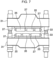
- Fig. 8 illustrates such a common existing cooling structure of the bearing box 37 with a water-cooling jacket.
- 33 denotes a segment roll
- 37 denotes a bearing box that supports a shaft of the segment roll 33 so that the shaft can rotate
- 39 denotes a bearing portion provided in the bearing box 37
- 41 denotes a seal portion
- 43 denotes a retainer
- 45 denotes a cooling water passage through which the cooling water for cooling mainly the bearing portion 39 passes
- 47 denotes a lid member for forming the cooling water passage 45.
- the cooling of the related art has been performed by a water-cooling jacket being configured.
- a water-cooling jacket is configured by the cooling water passage 45 being formed in the bearing box 37 as described above and being covered with the lid member 47.
- the casting method in which the cast piece-cooling water is reduced as much as possible in a curved zone positioned upstream of the casting to prevent a crack in a surface and a corner portion of a cast piece, has come to be conducted. Accordingly, the hitherto-obtained external cooling effect due to the cast piece-cooling water is decreased, and the thermal load applied to the bearing box 37 and the roll 35 increases.
- the present invention has been made to solve such a problem, and an object of the present invention is to provide a bearing box for a rotating roll that delivers high-temperature substance(s), the bearing box being capable of reducing a thermal load at a bearing portion and a seal portion provided adjacent to the bearing portion to effectively prevent rotation failure, breakage of the bearing portion, and hardening of the seal portion.
- the bearing box for a rotating roll that delivers a high-temperature substance includes: the first cooling liquid passage that is formed on the outer peripheral side of the bearing portion and through which a cooling liquid passes; and the second cooling liquid passage that is formed on the radially inner side relative to the first cooling liquid passage and on the outer peripheral side of the seal portion, the second cooling liquid passage communicating with the first cooling liquid passage to cause the cooling liquid to pass therethrough, and it is thereby possible to cool not only the bearing portion but also the seal portion to reduce the thermal load at the seal portion.
- rotation failure, breakage of the bearing portion, and hardening of the seal portion can effectively be prevented.
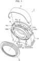
- a bearing box 1 for a segment roll mounted on a segment frame of a continuous casting machine will be described, as an example, based on Figs. 1 to 6 .
- a cooling liquid passage that is a distinctive portion of the present invention is mainly illustrated in Figs. 1 to 6
- a bearing portion 3 and a seal portion 5 are illustrated only by phantom lines, that is, chain double-dashed lines in Fig. 5 and the illustration thereof is omitted; however, the basic structures of the bearing portion 3 and the seal portion 5 are similar to those in Fig. 8 .
- the bearing box 1 includes the bearing portion 3 and the seal portion 5 provided adjacent to the bearing portion 3 (refer to Fig. 5 ), and the bearing box 1 includes a first cooling liquid passage 7 that is formed on the outer peripheral side of the bearing portion 3 and through which a cooling liquid passes and a second cooling liquid passage 9 that is formed on the radially inner side relative to the first cooling liquid passage 7 and on the outer peripheral side of the seal portion 5 and through which the cooling liquid passes.
- the first cooling liquid passage 7 and the second cooling liquid passage 9 are formed by a first jacket component 17 and a second jacket component 19 being mounted respectively on a first cooling liquid passage bottom portion 13 and a second cooling liquid passage bottom portion 15 formed in a main body 11 of the bearing box 1, so as to cover the respective cooling liquid passage bottom portions.
- the first jacket component 17 is constituted by a plate member having a semi-circular arc shape
- the second jacket component 19 is constituted by an annular member.
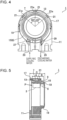
- Plural fixing components 21 for fixing the first jacket component 17 and the second jacket component 19 are provided, at a predetermined interval, on a portion of the first cooling liquid passage bottom portion 13 positioned on the second cooling liquid passage 9 side.
- each of the fixing components 21 has a protrusion 21a protruding toward the second cooling liquid passage 9 side, the first jacket component 17 is fixed to a top surface of each fixing component 21 by welding, and the second jacket component 19 is fixed to each protrusion 21a by welding.
- a water-cooling jacket structure is configured by the first jacket component 17 and the second jacket component 19 being fixed by welding to form a sealed structure.
- the cooling liquid flows not only in one cooling liquid passage having small resistance (the first cooling liquid passage 7 in the present embodiment), but the cooling liquid can be caused to flow all around both the cooling liquid passages without stagnating.
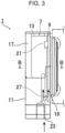
- a cooling liquid-supplying portion 23 and a cooling liquid-discharging portion 25 are provided in a lower portion of the main body 11 of the bearing box 1.
- the cooling liquid-supplying portion 23 is constituted by a passage 27 extending upward from the lower portion and bifurcating into two passages communicating respectively with the first cooling liquid passage 7 and the second cooling liquid passage 9.
- the cooling liquid-discharging portion 25 is also constituted by a passage 29 bifurcating into two passages, the two passages 29 communicating respectively with the first cooling liquid passage 7 and the second cooling liquid passage 9.
- the total of a width A of the first cooling liquid passage 7 and a width B of the second cooling liquid passage 9 is set to 1/2 or more of a width C of the bearing box 1.
- the problem to be solved with the present invention is how to prevent the inability of a bearing to rotate due to an oxidized lubricating oil stain caused by the temperature of the bearing portion 3 being raised by the bearing portion 3 and the seal portion 5 being heated by the radiant heat from a cast piece.
- the heat resistance of the bearing portion 3 is improved by increasing the water-cooling coverage with respect to the infrared radiation emitted from a high-temperature substance, that is, setting the water-cooling coverage to 1/2 or more.
- the bearing box 1, according to the present embodiment, configured as described above includes the first cooling liquid passage 7 and the second cooling liquid passage 9 that is formed on the radially inner side relative to the first cooling liquid passage 7 and on the outer peripheral side of the seal portion 5, the second cooling liquid passage 9 communicating with the first cooling liquid passage 7 to cause the cooling liquid to pass therethrough, and the water-cooling jacket thereby completely blocks the radiant heat from the cast piece to suppress not only an increase in the temperature of the bearing portion 3 but also an increase in the temperature of the seal portion 5. Thus, carbonization of a bearing lubricant and hardening of a seal can be prevented.
- the thermal flux moving toward the bearing portion 3 from the surface of the bearing box 1 at which the radiant heat generated from the cast piece arrives can mainly be reduced by the cooling liquid flowing in the first cooling liquid passage 7, and the thermal flux moving toward the bearing portion 3 and the seal portion 5 of a neck of the rotating roll from the surface of the bearing box 1 at which the radiant heat generated from the cast piece arrives can be reduced by the cooling liquid flowing in the second cooling liquid passage 9.
- the thermal load is effectively reduced.
- cooling liquid-supplying portion 23 and the cooling liquid-discharging portion 25 are provided in the lower portion of the main body 11 in the example illustrated in Figs. 1 to 6 , the positions at which the cooling liquid-supplying portion 23 and the cooling liquid-discharging portion 25 are provided are not particularly limited, and the cooling liquid-supplying portion 23 and the cooling liquid-discharging portion 25 may be provided, for example, at a side of the main body 11.
- the bearing box 1 for the segment roll mounted on the segment frame of the continuous casting machine is described as an example in the above-described embodiment, the bearing box according to the present invention is not limited to the bearing box 1 for the segment roll and is widely applicable to bearing boxes for a rotating roll that delivers a high-temperature substance.
- a test was conducted to verify the effects of the present invention.
- a bearing box for a cast piece-supporting roll (guide roll) of a steel-slab continuous casting machine was used, and the bearing box was cooled by cooling water.
- the test will be described.
- the test-target bearing box is a bearing box for the cast piece-supporting roll that supports a cast piece having a surface temperature of 700 to 900°C, and a bearing (rolling-element bearing) having an outside diameter of 170 mm, an inside diameter of 110 mm, and a width of 43 mm is mounted in the bearing box.
- the bearing box 1, according to the present invention, illustrated in Figs. 1 to 6 and the bearing box 37 illustrated in Fig. 8 for comparison were installed, and the temperatures of the bearing box 1 and the bearing box 37 during continuous casting were measured and compared with one another.
- cooling water was taken into each bearing box at 15L per minute, and the bearing box 1 and the bearing box 37 were cooled.
- the cooling water after cooling the bearing box 1 and the bearing box 37 was then caused to run down along the outer peripheries of the respective bearing boxes 1 and 37.
- the seal portion 41 is not covered with the lid member 47, whereas, in the example of present invention, the seal portion 5 is also covered with the second jacket component 19.
- the temperature of the seal portion 5 of the example of present invention is also decreased compared with the temperature of the seal portion of the example of the related art.
Landscapes
- Engineering & Computer Science (AREA)
- General Engineering & Computer Science (AREA)
- Mechanical Engineering (AREA)
- Mounting Of Bearings Or Others (AREA)
- Continuous Casting (AREA)
- Rolls And Other Rotary Bodies (AREA)
- Rolling Contact Bearings (AREA)
Claims (5)
- Lagergehäuse (1) für eine drehende Walze, die eine Hochtemperatursubstanz zuführt, wobei das Lagergehäuse (1) einen Lagerabschnitt (3) und einen Dichtungsabschnitt (5) beinhaltet, der angrenzend an den Lagerabschnitt (3) bereitgestellt ist, das Lagergehäuse (1) umfassend:einen ersten Kühlflüssigkeitsdurchgang (7), der an einer äußeren Umfangsseite des Lagerabschnitts (3) gebildet ist und durch den eine Kühlflüssigkeit verläuft; undeinen zweiten Kühlflüssigkeitsdurchgang (9), der an einer radial inneren Seite in Bezug auf den ersten Kühlflüssigkeitsdurchgang (7) und an einer äußeren Umfangsseite des Dichtungsabschnitts (5) gebildet ist, wobei der zweite Kühlflüssigkeitsdurchgang (9) mit dem ersten Kühlflüssigkeitsdurchgang (7) in Verbindung ist, um zu bewirken, dass die Kühlflüssigkeit dort hindurch verläuft.
- Lagergehäuse (1) für eine drehende Walze, die eine Hochtemperatursubstanz zuführt, gemäß Anspruch 1, wobei in einem Querschnitt des Lagergehäuses (1) in einer axialen Richtung der drehenden Walze eine Gesamtbreite des ersten Kühlflüssigkeitsdurchgangs (7) und des zweiten Kühlflüssigkeitsdurchgangs (9) 1/2 oder mehr einer Breite des Lagergehäuses (1) ist.
- Lagergehäuse (1) für eine drehende Walze, die eine Hochtemperatursubstanz zuführt, gemäß Anspruch 1 oder 2, das Lagergehäuse (1) umfassend: eine erste Mantelkomponente (17), die den ersten Kühlflüssigkeitsdurchgang (7) bildet; und eine zweite Mantelkomponente (19), die den zweiten Kühlflüssigkeitsdurchgang (9) bildet und eine Ringform aufweist.
- Lagergehäuse (1) für eine drehende Walze, die eine Hochtemperatursubstanz zuführt, gemäß Anspruch 3, wobei an einer Grenze zwischen dem ersten Kühlflüssigkeitsdurchgang (7) und dem zweiten Kühlflüssigkeitsdurchgang (9) eine Vielzahl von Befestigungskomponenten (21) zum Befestigen der ersten Mantelkomponente (17) und der zweiten Mantelkomponente (19) in einem vorbestimmten Abstand bereitgestellt sind.
- Lagergehäuse (1) für eine drehende Walze, die eine Hochtemperatursubstanz zuführt, gemäß Anspruch 4, wobei jede der Befestigungskomponenten (21) an einer Bodenfläche des ersten Kühlflüssigkeitsdurchgangs (7) befestigt ist und einen Vorsprung (21a) aufweist, der in Richtung einer Seite des zweiten Kühlflüssigkeitsdurchgangs (9) hervorsteht, die erste Mantelkomponente (17) an einer oberen Fläche der Befestigungskomponente (21) befestigt ist und die zweite Mantelkomponente (19) an dem Vorsprung der Befestigungskomponente (21) befestigt ist.
Applications Claiming Priority (2)
| Application Number | Priority Date | Filing Date | Title |
|---|---|---|---|
| JP2019168952A JP7311370B2 (ja) | 2019-09-18 | 2019-09-18 | 高温物体を搬送する回転ロールの軸受箱 |
| PCT/JP2020/035402 WO2021054426A1 (ja) | 2019-09-18 | 2020-09-18 | 高温物体を搬送する回転ロールの軸受箱 |
Publications (3)
| Publication Number | Publication Date |
|---|---|
| EP4005698A1 EP4005698A1 (de) | 2022-06-01 |
| EP4005698A4 EP4005698A4 (de) | 2022-08-31 |
| EP4005698B1 true EP4005698B1 (de) | 2023-08-23 |
Family
ID=74877284
Family Applications (1)
| Application Number | Title | Priority Date | Filing Date |
|---|---|---|---|
| EP20866469.8A Active EP4005698B1 (de) | 2019-09-18 | 2020-09-18 | Lagergehäuse für rotierende walze, die ein hochtemperaturobjekt trägt |
Country Status (6)
| Country | Link |
|---|---|
| US (1) | US11933363B2 (de) |
| EP (1) | EP4005698B1 (de) |
| JP (1) | JP7311370B2 (de) |
| KR (1) | KR102644414B1 (de) |
| CN (1) | CN114375232B (de) |
| WO (1) | WO2021054426A1 (de) |
Families Citing this family (1)
| Publication number | Priority date | Publication date | Assignee | Title |
|---|---|---|---|---|
| CN117182016A (zh) * | 2022-05-31 | 2023-12-08 | 斯凯孚公司 | 支承单元和包括该支承单元的连铸导向辊组件 |
Citations (3)
| Publication number | Priority date | Publication date | Assignee | Title |
|---|---|---|---|---|
| JP2004148407A (ja) | 2003-11-28 | 2004-05-27 | Jfe Steel Kk | 連続鋳造機用ロール軸受の密封装置、密封方法および連続鋳造機 |
| JP2006035236A (ja) | 2004-07-22 | 2006-02-09 | Kobe Steel Ltd | 連続鋳造設備における鋳片案内装置 |
| DE102016224761A1 (de) | 2015-12-11 | 2017-06-14 | Sms Group Gmbh | Lagerbock zur Aufnahme eines Lagers für eine Rolle |
Family Cites Families (24)
| Publication number | Priority date | Publication date | Assignee | Title |
|---|---|---|---|---|
| JPS5482327A (en) * | 1977-12-14 | 1979-06-30 | Kawasaki Steel Co | Intermediate bearing device for devided casttstrippguidinggroller in continuous casting apparatus |
| DE3319537A1 (de) * | 1983-05-28 | 1984-11-29 | Klein, Schanzlin & Becker Ag, 6710 Frankenthal | Einrichtung zur oelversorgung eines hoch waermebelasteten wellenlagers |
| DE4114842C2 (de) * | 1991-05-07 | 1995-08-03 | Skf Gmbh | Mit einer Dichtungsanordnung versehenes Wälzlager |
| DE4207042C1 (en) | 1992-03-02 | 1993-09-16 | Mannesmann Ag, 40213 Duesseldorf, De | Coolant coupling for roll device - with good sealant properties provided by elastic socket feeding coolant into roll bore |
| RU2038187C1 (ru) | 1992-12-14 | 1995-06-27 | Производственное объединение "Южуралмаш" | Устройство для непрерывной разливки металла |
| JP3083720B2 (ja) * | 1994-12-16 | 2000-09-04 | 住友重機械工業株式会社 | 連続鋳造設備におけるロールセグメント冷却装置 |
| US5915843A (en) * | 1996-07-12 | 1999-06-29 | The Torrington Company | Fluid-cooled bearing housing |
| JPH10274247A (ja) * | 1997-03-27 | 1998-10-13 | Nisshin Steel Co Ltd | 軸受箱及びフートロールセグメント |
| JP2003290891A (ja) | 2002-04-03 | 2003-10-14 | Jfe Steel Kk | 連続鋳造機のテーブルロール用軸受装置および軸受の冷却方法 |
| JP2004011766A (ja) * | 2002-06-06 | 2004-01-15 | Nsk Ltd | 軸受装置 |
| DE10302474A1 (de) * | 2003-01-23 | 2004-08-05 | Sms Demag Ag | Kühlung von Rollen in Stranggießanlagen |
| DE102005052067A1 (de) | 2005-10-28 | 2007-05-03 | Georg Springmann Industrie- Und Bergbautechnik Gmbh | Vorrichtung zum Ankuppeln einer Kühlmittelzuführung an eine Walze |
| JP5217719B2 (ja) | 2008-07-16 | 2013-06-19 | 新日鐵住金株式会社 | 連続鋳造設備におけるロールセグメント装置 |
| JP5659521B2 (ja) * | 2009-04-06 | 2015-01-28 | 株式会社ジェイテクト | 転がり軸受装置 |
| KR101344511B1 (ko) | 2009-09-04 | 2013-12-24 | 에스엠에스 콘캐스트 에이지 | 연속 주조 설비용 롤러 및 롤러 장치 |
| CN201823915U (zh) | 2010-10-27 | 2011-05-11 | 威尔机械江苏有限公司 | 连铸机轴承座 |
| CN104114887B (zh) * | 2011-10-06 | 2016-08-24 | Skf公司 | 热电功率获取轴承配置 |
| JP2013103254A (ja) * | 2011-11-15 | 2013-05-30 | Sumitomo Heavy Industries Techno-Fort Co Ltd | 連続鋳造設備のガイドロール冷却装置 |
| AT513431B1 (de) | 2012-09-28 | 2015-10-15 | Primetals Technologies Austria GmbH | Gekühlte, mehrfach gelagerte Strangführungsrolle |
| AT514625B1 (de) | 2013-07-24 | 2018-07-15 | Primetals Technologies Austria GmbH | Gekühlte Strangführungsrolle |
| CN203868150U (zh) * | 2014-03-25 | 2014-10-08 | 新疆金特钢铁股份有限公司 | 一种皮带机改向滚筒水冷式轴承座 |
| CN206206423U (zh) | 2016-11-21 | 2017-05-31 | 南京磁谷科技有限公司 | 一种轴承冷却结构 |
| CN207154718U (zh) | 2017-09-26 | 2018-03-30 | 黄石市火炬科技实业有限责任公司 | 一种用于连铸辊组的冷却水循环装置 |
| EP4159343A1 (de) * | 2021-09-29 | 2023-04-05 | Primetals Technologies Austria GmbH | Stehlager und produktionsanlage mit solch einem stehlager |
-
2019
- 2019-09-18 JP JP2019168952A patent/JP7311370B2/ja active Active
-
2020
- 2020-09-18 CN CN202080064192.6A patent/CN114375232B/zh active Active
- 2020-09-18 KR KR1020227008493A patent/KR102644414B1/ko active Active
- 2020-09-18 WO PCT/JP2020/035402 patent/WO2021054426A1/ja not_active Ceased
- 2020-09-18 US US17/761,775 patent/US11933363B2/en active Active
- 2020-09-18 EP EP20866469.8A patent/EP4005698B1/de active Active
Patent Citations (3)
| Publication number | Priority date | Publication date | Assignee | Title |
|---|---|---|---|---|
| JP2004148407A (ja) | 2003-11-28 | 2004-05-27 | Jfe Steel Kk | 連続鋳造機用ロール軸受の密封装置、密封方法および連続鋳造機 |
| JP2006035236A (ja) | 2004-07-22 | 2006-02-09 | Kobe Steel Ltd | 連続鋳造設備における鋳片案内装置 |
| DE102016224761A1 (de) | 2015-12-11 | 2017-06-14 | Sms Group Gmbh | Lagerbock zur Aufnahme eines Lagers für eine Rolle |
Also Published As
| Publication number | Publication date |
|---|---|
| US20220373034A1 (en) | 2022-11-24 |
| CN114375232A (zh) | 2022-04-19 |
| US11933363B2 (en) | 2024-03-19 |
| EP4005698A1 (de) | 2022-06-01 |
| BR112022005050A2 (pt) | 2022-06-14 |
| KR102644414B1 (ko) | 2024-03-06 |
| KR20220044595A (ko) | 2022-04-08 |
| CN114375232B (zh) | 2024-04-05 |
| EP4005698A4 (de) | 2022-08-31 |
| JP2021045765A (ja) | 2021-03-25 |
| WO2021054426A1 (ja) | 2021-03-25 |
| JP7311370B2 (ja) | 2023-07-19 |
Similar Documents
| Publication | Publication Date | Title |
|---|---|---|
| EP4005698B1 (de) | Lagergehäuse für rotierende walze, die ein hochtemperaturobjekt trägt | |
| KR101377090B1 (ko) | 쌍롤식 주조기와 그 작동장치 및 방법 | |
| RU2553139C2 (ru) | Распределяющий элемент, роликовая линия и устройство для непрерывной разливки | |
| EP4006369B1 (de) | Lagergehäuse für eine rotierende walze, kühlverfahren für dieses lagergehäuse, stahlstranggussmaschine und -verfahren | |
| RU2553140C2 (ru) | Распределяющий элемент, роликовая линия и устройство для непрерывной разливки | |
| RU2805517C2 (ru) | Корпус подшипника для вращающегося валка, который подает высокотемпературное вещество или вещества | |
| EP2682202B1 (de) | Rollleitung und Stranggießvorrichtung | |
| US7594535B2 (en) | Twin roll caster, and equipment and method for operating the same | |
| BR112022005050B1 (pt) | Caixa de mancal para rolo rotativo que entrega substância(s) de alta temperatura | |
| RU2788541C1 (ru) | Корпус подшипника для вращающегося валка, способ охлаждения корпуса подшипника для вращающегося валка, машины непрерывного литья заготовок из стали и способ непрерывного литья заготовок из стали | |
| JP6835016B2 (ja) | 軸受箱及び軸受箱の冷却方法 | |
| EP2680990B1 (de) | Verfahren zur verlängerung der lebensdauer einer walzlinie | |
| BR112022004593B1 (pt) | Caixa de mancal para rolete rotativo, método para resfriar caixa de mancal para rolete rotativo, máquina de fundição contínua de aço e método de fundição contínua de aço | |
| RU2852791C2 (ru) | Стояковый подшипник и производственная установка, имеющая такой стояковый подшипник | |
| KR100489015B1 (ko) | 쌍롤식 박판주조기용 냉각롤 | |
| RU2022107189A (ru) | Корпус подшипника для вращающегося валка, который подает высокотемпературное вещество или вещества | |
| JPH03106544A (ja) | 連続鋳造鋳型の潤滑剤供給方法 |
Legal Events
| Date | Code | Title | Description |
|---|---|---|---|
| STAA | Information on the status of an ep patent application or granted ep patent |
Free format text: STATUS: THE INTERNATIONAL PUBLICATION HAS BEEN MADE |
|
| PUAI | Public reference made under article 153(3) epc to a published international application that has entered the european phase |
Free format text: ORIGINAL CODE: 0009012 |
|
| STAA | Information on the status of an ep patent application or granted ep patent |
Free format text: STATUS: REQUEST FOR EXAMINATION WAS MADE |
|
| 17P | Request for examination filed |
Effective date: 20220225 |
|
| AK | Designated contracting states |
Kind code of ref document: A1 Designated state(s): AL AT BE BG CH CY CZ DE DK EE ES FI FR GB GR HR HU IE IS IT LI LT LU LV MC MK MT NL NO PL PT RO RS SE SI SK SM TR |
|
| A4 | Supplementary search report drawn up and despatched |
Effective date: 20220802 |
|
| RIC1 | Information provided on ipc code assigned before grant |
Ipc: F16J 15/16 20060101ALI20220727BHEP Ipc: F16C 35/04 20060101ALI20220727BHEP Ipc: F16C 37/00 20060101ALI20220727BHEP Ipc: F16C 13/02 20060101ALI20220727BHEP Ipc: B22D 11/128 20060101AFI20220727BHEP |
|
| DAV | Request for validation of the european patent (deleted) | ||
| DAX | Request for extension of the european patent (deleted) | ||
| RIC1 | Information provided on ipc code assigned before grant |
Ipc: F16C 37/00 20060101ALN20230220BHEP Ipc: F16J 15/324 20160101ALI20230220BHEP Ipc: F16J 15/16 20060101ALI20230220BHEP Ipc: F16C 35/04 20060101ALI20230220BHEP Ipc: F16C 13/02 20060101ALI20230220BHEP Ipc: B22D 11/128 20060101AFI20230220BHEP |
|
| GRAP | Despatch of communication of intention to grant a patent |
Free format text: ORIGINAL CODE: EPIDOSNIGR1 |
|
| STAA | Information on the status of an ep patent application or granted ep patent |
Free format text: STATUS: GRANT OF PATENT IS INTENDED |
|
| RIC1 | Information provided on ipc code assigned before grant |
Ipc: F16C 37/00 20060101ALN20230322BHEP Ipc: F16J 15/324 20160101ALI20230322BHEP Ipc: F16J 15/16 20060101ALI20230322BHEP Ipc: F16C 35/04 20060101ALI20230322BHEP Ipc: F16C 13/02 20060101ALI20230322BHEP Ipc: B22D 11/128 20060101AFI20230322BHEP |
|
| INTG | Intention to grant announced |
Effective date: 20230426 |
|
| RIN1 | Information on inventor provided before grant (corrected) |
Inventor name: OHARA, NORIAKI Inventor name: FUJII, AKITAKA Inventor name: ITO, SHINYA Inventor name: ISOZAKI, KENJI |
|
| GRAS | Grant fee paid |
Free format text: ORIGINAL CODE: EPIDOSNIGR3 |
|
| GRAA | (expected) grant |
Free format text: ORIGINAL CODE: 0009210 |
|
| STAA | Information on the status of an ep patent application or granted ep patent |
Free format text: STATUS: THE PATENT HAS BEEN GRANTED |
|
| AK | Designated contracting states |
Kind code of ref document: B1 Designated state(s): AL AT BE BG CH CY CZ DE DK EE ES FI FR GB GR HR HU IE IS IT LI LT LU LV MC MK MT NL NO PL PT RO RS SE SI SK SM TR |
|
| REG | Reference to a national code |
Ref country code: GB Ref legal event code: FG4D |
|
| REG | Reference to a national code |
Ref country code: CH Ref legal event code: EP |
|
| REG | Reference to a national code |
Ref country code: IE Ref legal event code: FG4D |
|
| REG | Reference to a national code |
Ref country code: DE Ref legal event code: R096 Ref document number: 602020016424 Country of ref document: DE |
|
| REG | Reference to a national code |
Ref country code: LT Ref legal event code: MG9D |
|
| REG | Reference to a national code |
Ref country code: NL Ref legal event code: MP Effective date: 20230823 |
|
| PG25 | Lapsed in a contracting state [announced via postgrant information from national office to epo] |
Ref country code: GR Free format text: LAPSE BECAUSE OF FAILURE TO SUBMIT A TRANSLATION OF THE DESCRIPTION OR TO PAY THE FEE WITHIN THE PRESCRIBED TIME-LIMIT Effective date: 20231124 |
|
| PG25 | Lapsed in a contracting state [announced via postgrant information from national office to epo] |
Ref country code: IS Free format text: LAPSE BECAUSE OF FAILURE TO SUBMIT A TRANSLATION OF THE DESCRIPTION OR TO PAY THE FEE WITHIN THE PRESCRIBED TIME-LIMIT Effective date: 20231223 |
|
| PG25 | Lapsed in a contracting state [announced via postgrant information from national office to epo] |
Ref country code: SE Free format text: LAPSE BECAUSE OF FAILURE TO SUBMIT A TRANSLATION OF THE DESCRIPTION OR TO PAY THE FEE WITHIN THE PRESCRIBED TIME-LIMIT Effective date: 20230823 Ref country code: RS Free format text: LAPSE BECAUSE OF FAILURE TO SUBMIT A TRANSLATION OF THE DESCRIPTION OR TO PAY THE FEE WITHIN THE PRESCRIBED TIME-LIMIT Effective date: 20230823 Ref country code: PT Free format text: LAPSE BECAUSE OF FAILURE TO SUBMIT A TRANSLATION OF THE DESCRIPTION OR TO PAY THE FEE WITHIN THE PRESCRIBED TIME-LIMIT Effective date: 20231226 Ref country code: NO Free format text: LAPSE BECAUSE OF FAILURE TO SUBMIT A TRANSLATION OF THE DESCRIPTION OR TO PAY THE FEE WITHIN THE PRESCRIBED TIME-LIMIT Effective date: 20231123 Ref country code: NL Free format text: LAPSE BECAUSE OF FAILURE TO SUBMIT A TRANSLATION OF THE DESCRIPTION OR TO PAY THE FEE WITHIN THE PRESCRIBED TIME-LIMIT Effective date: 20230823 Ref country code: LV Free format text: LAPSE BECAUSE OF FAILURE TO SUBMIT A TRANSLATION OF THE DESCRIPTION OR TO PAY THE FEE WITHIN THE PRESCRIBED TIME-LIMIT Effective date: 20230823 Ref country code: LT Free format text: LAPSE BECAUSE OF FAILURE TO SUBMIT A TRANSLATION OF THE DESCRIPTION OR TO PAY THE FEE WITHIN THE PRESCRIBED TIME-LIMIT Effective date: 20230823 Ref country code: IS Free format text: LAPSE BECAUSE OF FAILURE TO SUBMIT A TRANSLATION OF THE DESCRIPTION OR TO PAY THE FEE WITHIN THE PRESCRIBED TIME-LIMIT Effective date: 20231223 Ref country code: HR Free format text: LAPSE BECAUSE OF FAILURE TO SUBMIT A TRANSLATION OF THE DESCRIPTION OR TO PAY THE FEE WITHIN THE PRESCRIBED TIME-LIMIT Effective date: 20230823 Ref country code: GR Free format text: LAPSE BECAUSE OF FAILURE TO SUBMIT A TRANSLATION OF THE DESCRIPTION OR TO PAY THE FEE WITHIN THE PRESCRIBED TIME-LIMIT Effective date: 20231124 Ref country code: FI Free format text: LAPSE BECAUSE OF FAILURE TO SUBMIT A TRANSLATION OF THE DESCRIPTION OR TO PAY THE FEE WITHIN THE PRESCRIBED TIME-LIMIT Effective date: 20230823 |
|
| REG | Reference to a national code |
Ref country code: AT Ref legal event code: UEP Ref document number: 1601985 Country of ref document: AT Kind code of ref document: T Effective date: 20230823 |
|
| PG25 | Lapsed in a contracting state [announced via postgrant information from national office to epo] |
Ref country code: PL Free format text: LAPSE BECAUSE OF FAILURE TO SUBMIT A TRANSLATION OF THE DESCRIPTION OR TO PAY THE FEE WITHIN THE PRESCRIBED TIME-LIMIT Effective date: 20230823 |
|
| PG25 | Lapsed in a contracting state [announced via postgrant information from national office to epo] |
Ref country code: ES Free format text: LAPSE BECAUSE OF FAILURE TO SUBMIT A TRANSLATION OF THE DESCRIPTION OR TO PAY THE FEE WITHIN THE PRESCRIBED TIME-LIMIT Effective date: 20230823 |
|
| PG25 | Lapsed in a contracting state [announced via postgrant information from national office to epo] |
Ref country code: SM Free format text: LAPSE BECAUSE OF FAILURE TO SUBMIT A TRANSLATION OF THE DESCRIPTION OR TO PAY THE FEE WITHIN THE PRESCRIBED TIME-LIMIT Effective date: 20230823 Ref country code: RO Free format text: LAPSE BECAUSE OF FAILURE TO SUBMIT A TRANSLATION OF THE DESCRIPTION OR TO PAY THE FEE WITHIN THE PRESCRIBED TIME-LIMIT Effective date: 20230823 Ref country code: ES Free format text: LAPSE BECAUSE OF FAILURE TO SUBMIT A TRANSLATION OF THE DESCRIPTION OR TO PAY THE FEE WITHIN THE PRESCRIBED TIME-LIMIT Effective date: 20230823 Ref country code: EE Free format text: LAPSE BECAUSE OF FAILURE TO SUBMIT A TRANSLATION OF THE DESCRIPTION OR TO PAY THE FEE WITHIN THE PRESCRIBED TIME-LIMIT Effective date: 20230823 Ref country code: DK Free format text: LAPSE BECAUSE OF FAILURE TO SUBMIT A TRANSLATION OF THE DESCRIPTION OR TO PAY THE FEE WITHIN THE PRESCRIBED TIME-LIMIT Effective date: 20230823 Ref country code: CZ Free format text: LAPSE BECAUSE OF FAILURE TO SUBMIT A TRANSLATION OF THE DESCRIPTION OR TO PAY THE FEE WITHIN THE PRESCRIBED TIME-LIMIT Effective date: 20230823 Ref country code: SK Free format text: LAPSE BECAUSE OF FAILURE TO SUBMIT A TRANSLATION OF THE DESCRIPTION OR TO PAY THE FEE WITHIN THE PRESCRIBED TIME-LIMIT Effective date: 20230823 |
|
| REG | Reference to a national code |
Ref country code: CH Ref legal event code: PL |
|
| PG25 | Lapsed in a contracting state [announced via postgrant information from national office to epo] |
Ref country code: LU Free format text: LAPSE BECAUSE OF NON-PAYMENT OF DUE FEES Effective date: 20230918 |
|
| REG | Reference to a national code |
Ref country code: DE Ref legal event code: R026 Ref document number: 602020016424 Country of ref document: DE |
|
| PLBI | Opposition filed |
Free format text: ORIGINAL CODE: 0009260 |
|
| REG | Reference to a national code |
Ref country code: BE Ref legal event code: MM Effective date: 20230930 |
|
| PG25 | Lapsed in a contracting state [announced via postgrant information from national office to epo] |
Ref country code: LU Free format text: LAPSE BECAUSE OF NON-PAYMENT OF DUE FEES Effective date: 20230918 Ref country code: MC Free format text: LAPSE BECAUSE OF FAILURE TO SUBMIT A TRANSLATION OF THE DESCRIPTION OR TO PAY THE FEE WITHIN THE PRESCRIBED TIME-LIMIT Effective date: 20230823 |
|
| PLAX | Notice of opposition and request to file observation + time limit sent |
Free format text: ORIGINAL CODE: EPIDOSNOBS2 |
|
| 26 | Opposition filed |
Opponent name: SMS GROUP GMBH Effective date: 20240522 |
|
| REG | Reference to a national code |
Ref country code: IE Ref legal event code: MM4A |
|
| PG25 | Lapsed in a contracting state [announced via postgrant information from national office to epo] |
Ref country code: IE Free format text: LAPSE BECAUSE OF NON-PAYMENT OF DUE FEES Effective date: 20230918 |
|
| PG25 | Lapsed in a contracting state [announced via postgrant information from national office to epo] |
Ref country code: CH Free format text: LAPSE BECAUSE OF NON-PAYMENT OF DUE FEES Effective date: 20230930 |
|
| PG25 | Lapsed in a contracting state [announced via postgrant information from national office to epo] |
Ref country code: IE Free format text: LAPSE BECAUSE OF NON-PAYMENT OF DUE FEES Effective date: 20230918 Ref country code: CH Free format text: LAPSE BECAUSE OF NON-PAYMENT OF DUE FEES Effective date: 20230930 Ref country code: SI Free format text: LAPSE BECAUSE OF FAILURE TO SUBMIT A TRANSLATION OF THE DESCRIPTION OR TO PAY THE FEE WITHIN THE PRESCRIBED TIME-LIMIT Effective date: 20230823 |
|
| PLBB | Reply of patent proprietor to notice(s) of opposition received |
Free format text: ORIGINAL CODE: EPIDOSNOBS3 |
|
| PG25 | Lapsed in a contracting state [announced via postgrant information from national office to epo] |
Ref country code: BE Free format text: LAPSE BECAUSE OF NON-PAYMENT OF DUE FEES Effective date: 20230930 |
|
| PG25 | Lapsed in a contracting state [announced via postgrant information from national office to epo] |
Ref country code: BG Free format text: LAPSE BECAUSE OF FAILURE TO SUBMIT A TRANSLATION OF THE DESCRIPTION OR TO PAY THE FEE WITHIN THE PRESCRIBED TIME-LIMIT Effective date: 20230823 |
|
| PG25 | Lapsed in a contracting state [announced via postgrant information from national office to epo] |
Ref country code: BG Free format text: LAPSE BECAUSE OF FAILURE TO SUBMIT A TRANSLATION OF THE DESCRIPTION OR TO PAY THE FEE WITHIN THE PRESCRIBED TIME-LIMIT Effective date: 20230823 |
|
| GBPC | Gb: european patent ceased through non-payment of renewal fee |
Effective date: 20240918 |
|
| PG25 | Lapsed in a contracting state [announced via postgrant information from national office to epo] |
Ref country code: GB Free format text: LAPSE BECAUSE OF NON-PAYMENT OF DUE FEES Effective date: 20240918 |
|
| PG25 | Lapsed in a contracting state [announced via postgrant information from national office to epo] |
Ref country code: CY Free format text: LAPSE BECAUSE OF FAILURE TO SUBMIT A TRANSLATION OF THE DESCRIPTION OR TO PAY THE FEE WITHIN THE PRESCRIBED TIME-LIMIT; INVALID AB INITIO Effective date: 20200918 |
|
| PG25 | Lapsed in a contracting state [announced via postgrant information from national office to epo] |
Ref country code: HU Free format text: LAPSE BECAUSE OF FAILURE TO SUBMIT A TRANSLATION OF THE DESCRIPTION OR TO PAY THE FEE WITHIN THE PRESCRIBED TIME-LIMIT; INVALID AB INITIO Effective date: 20200918 |
|
| PGFP | Annual fee paid to national office [announced via postgrant information from national office to epo] |
Ref country code: DE Payment date: 20250730 Year of fee payment: 6 |
|
| PGFP | Annual fee paid to national office [announced via postgrant information from national office to epo] |
Ref country code: TR Payment date: 20250911 Year of fee payment: 6 Ref country code: IT Payment date: 20250825 Year of fee payment: 6 |
|
| PGFP | Annual fee paid to national office [announced via postgrant information from national office to epo] |
Ref country code: FR Payment date: 20250808 Year of fee payment: 6 Ref country code: AT Payment date: 20250827 Year of fee payment: 6 |