EP4005528B1 - Clip für ein kieferorthopädisches bracket - Google Patents
Clip für ein kieferorthopädisches bracket Download PDFInfo
- Publication number
- EP4005528B1 EP4005528B1 EP21206149.3A EP21206149A EP4005528B1 EP 4005528 B1 EP4005528 B1 EP 4005528B1 EP 21206149 A EP21206149 A EP 21206149A EP 4005528 B1 EP4005528 B1 EP 4005528B1
- Authority
- EP
- European Patent Office
- Prior art keywords
- clip
- bracket
- guide
- bracket body
- slot
- Prior art date
- Legal status (The legal status is an assumption and is not a legal conclusion. Google has not performed a legal analysis and makes no representation as to the accuracy of the status listed.)
- Active
Links
Images


Classifications
-
- A—HUMAN NECESSITIES
- A61—MEDICAL OR VETERINARY SCIENCE; HYGIENE
- A61C—DENTISTRY; APPARATUS OR METHODS FOR ORAL OR DENTAL HYGIENE
- A61C7/00—Orthodontics, i.e. obtaining or maintaining the desired position of teeth, e.g. by straightening, evening, regulating, separating, or by correcting malocclusions
- A61C7/12—Brackets; Arch wires; Combinations thereof; Accessories therefor
- A61C7/28—Securing arch wire to bracket
- A61C7/287—Sliding locks
-
- A—HUMAN NECESSITIES
- A61—MEDICAL OR VETERINARY SCIENCE; HYGIENE
- A61C—DENTISTRY; APPARATUS OR METHODS FOR ORAL OR DENTAL HYGIENE
- A61C7/00—Orthodontics, i.e. obtaining or maintaining the desired position of teeth, e.g. by straightening, evening, regulating, separating, or by correcting malocclusions
- A61C7/12—Brackets; Arch wires; Combinations thereof; Accessories therefor
- A61C7/14—Brackets; Fixing brackets to teeth
-
- A—HUMAN NECESSITIES
- A61—MEDICAL OR VETERINARY SCIENCE; HYGIENE
- A61C—DENTISTRY; APPARATUS OR METHODS FOR ORAL OR DENTAL HYGIENE
- A61C7/00—Orthodontics, i.e. obtaining or maintaining the desired position of teeth, e.g. by straightening, evening, regulating, separating, or by correcting malocclusions
- A61C7/12—Brackets; Arch wires; Combinations thereof; Accessories therefor
- A61C7/28—Securing arch wire to bracket
Definitions
- the invention relates to a bracket with a clip.
- brackets are glued to the patient's teeth to be treated and connected to each other by an orthodontic wire.
- the brackets have a pad for connection to the tooth and a bracket body with a slot that accommodates the arch wire, with a clip provided on the bracket body to hold the arch wire in the slot.
- the brackets can be lingual or buccal brackets, i.e. intended to be placed on the lingual or buccal side of the patient's teeth.
- orthodontic wires made of a shape memory material are often inserted into the brackets in order to achieve a "rough" alignment of the teeth. Only towards the end of orthodontic treatment are steel wires used, for example, to move the teeth as precisely as possible into a defined position.
- the archwire and the clip can be made of a shape memory material.
- the most important shape memory materials include Cu-Zn-X (X: Si, Sn, Al) alloys and the intermetallic NiTi alloy (nickel content of approx. 55 wt.%), whereby the NiTi alloy has gained greater technological importance due to its more favorable properties.
- the shape memory effect is based on a thermoelastic martensite transformation, a reversible phase transformation caused by shearing of the lattice planes. Cooling of the high-temperature phase, called austenite, below the alloy-specific martensite start temperature leads to the phase transformation without shape change and without irreversible plastic deformation, as is the case with steels.
- Shape memory alloys can be easily deformed in the martensitic state; the reversible deformation can be up to 8% for NiTi. This deformation is permanent as long as the alloy is in the martensitic state. Heating above the alloy-specific austenite start temperature then leads to the original shape being restored.
- an orthodontic component made of a shape memory material In order to convert an orthodontic component made of a shape memory material into a target geometry, it is brought into the desired target geometry in a special baking mold and then heated to a transition temperature specific to the shape memory material. The orthodontic component is then cooled down again and inserted into a patient's orthodontic appliance, e.g. fixed lingual or buccal brackets, while being deformed. In the patient's mouth, the elastically deformed component, e.g. an archwire or a clip, is heated again and remembers its target geometry, into which it then tries to deform itself.
- a patient's orthodontic appliance e.g. fixed lingual or buccal brackets
- From the DE102017211867A1 is an arrangement with a bracket with a pad and a bracket body with a slot for receiving an orthodontic wire as well as a clip assigned to the bracket made of a shape memory material for closing and releasing the slot of the bracket in order to hold the orthodontic wire in the slot in a closed position or to release it in an open position for removal from the slot.
- a first end of the clip is a fixing end that is firmly connected to the bracket.
- a second end of the clip is a free end that rests against the bracket in the open position, releasing the slot, and rests against the bracket across the slot in the closed position.
- a disadvantage of the known clip is that the fixing element is firmly connected to the bracket body, which is complex to manufacture.
- Another disadvantage is that the archwire has too much play in the slot or the clip does not hold the archwire firmly enough, which can lead to a tilting of the archwire in the slot in a horizontal slot and an angulation of the archwire in the slot in a vertical slot.
- a bracket with a pad, a bracket body and a slot in the bracket body is known, in which slot an orthodontic wire can be arranged.
- a clip is provided to hold the wire in the slot.
- the clip has Cross-sectional view essentially has a C-shape, wherein a bracket body end of the clip is guided in the bracket body so as to be movable in a purely translational manner and a wire end of the clip in a first position overlaps the slot to hold the wire in the slot and is arranged on the bracket body in a second position to change the wire.
- the bracket body end of the clip is movable in a translational manner in a channel in the bracket body, wherein a guide channel is provided in the bracket body for this purpose.
- the guide channel is designed to be linear in order to guide the bracket body end of the clip in a purely translational manner in the bracket body.
- the disadvantage of this arrangement is that food residues or deposits of saliva can build up in the guide channel and this makes it more difficult to guide the bracket body end of the clip in the guide channel.
- the US 2020/0375699 A1 shows a fixed orthodontic appliance having brackets attached to a patient's tooth.
- the brackets have a pad, a bracket body and a clip, the clip having a C-shape in cross-sectional view.
- a body end of the clip is fixed to the bracket body and a free end of the clip is arranged so as to be pivotable - towards and away from the fixed body end.
- a wire can be arranged inside the C-shape, delimited by the two opposite ends of the clip. The wire can move freely inside the C-shape of the clip.
- a slot for defined guidance of the wire is therefore not provided.
- the clip, the arrangement of the clip on the bracket body and the function of the clip are therefore not intended for holding the wire in a slot.
- the US2015/0173859A1 , the US2018/0042700A1 , the US2017/0245963A1 , the US2013/0171579A1 and the US2012/0135364A1 show brackets with a bracket body, a pad and a slot, with a clip guide channel for a clip being formed in the bracket body near the pad, perpendicular to the slot.
- An associated clip has a linear clip guide section for receiving in the linear clip guide channel of the bracket and has an opposite end for engaging over the slot or the wire arranged therein. If the clip engages over the slot, the free end of the clip guide section protrudes over the bracket body: see. Fig. 1 in the US2015/0173859A1 , Fig.
- the clip guide channel section in the patient's mouth causes interference, e.g. with the tongue.
- a clip guide channel running lengthways through the bracket body is disadvantageous because food particles get stuck in it and hardening, e.g. calcifications, so that it is often difficult to remove the clip from the bracket after some time in the patient's mouth.
- the encrustations in the clip guide channel prevent the clip from moving relative to the bracket.
- the object of the present invention is therefore to provide a clip for a bracket which allows easy handling of the bracket and holds the archwire well in the slot.
- the object is achieved according to the invention by a bracket with a C-shaped clip.
- the bracket body advantageously has a bracket body ramp for sliding on the retaining support ramp.
- the bracket body ramp has a bracket body retaining lug for interacting with a clip ramp lug, in particular at the transition from the retaining support ramp to the C-shape of the clip, in order to hold the clip on the bracket in the open state, wherein in this state the guide section of the clip is in engagement with the clip receptacle of the bracket, so that the clip is held elastically on the bracket by its C-shape.
- one end of the C-shape of the clip continues into a guide section which is provided for guiding engagement in a clip receptacle of the bracket in order to hold the clip pivotably on the bracket, and the other end of the C-shape continues into a holding support which widens in the medial-lateral direction in order to hold the orthodontic wire in the slot.
- the guide section of the clip has a guide projection protruding in the medial direction and a guide projection protruding in the lateral direction, wherein the guide projections are opposite one another in the medial-lateral direction and/or protrude 0.1 to 0.8 mm, in particular 0.2 mm.
- a thickness of the retaining pad of the clip decreases in the direction of the free end, in particular linearly, in order to make the retaining pad elastic and to facilitate sliding the retaining pad onto the orthodontic wire or bracket.
- the retaining pad of the clip has a retaining pad ramp curved in the caudal direction to facilitate sliding the retaining pad onto the orthodontic wire or bracket.
- the retaining support of the clip has an engagement portion, in particular formed as a projection, e.g. as a ball or hook, in order to bring it into engagement with a rubber or a ligature and/or to move the end of the clip, which has the retaining support, away from the bracket, in particular to push it away, or to move it towards the bracket, in particular to push it onto the bracket, in order to open or close the clip, in particular by hand.
- an engagement portion in particular formed as a projection, e.g. as a ball or hook, in order to bring it into engagement with a rubber or a ligature and/or to move the end of the clip, which has the retaining support, away from the bracket, in particular to push it away, or to move it towards the bracket, in particular to push it onto the bracket, in order to open or close the clip, in particular by hand.
- an upper jaw clip has a length of 2-8mm, in particular 3.5mm, and/or a thickness of 0.2 to 0.6mm, in particular 0.3mm, and/or a width of 0.5 to 2.5mm, in particular 1.1mm
- a lower jaw clip has a length of 2-8mm, in particular 3.5mm, and/or a thickness of 0.2 to 0.6mm, in particular 0.3mm, and/or a width of 0.5 to 2.5mm, in particular 0.9mm.
- the holding support of the clip has a thickness of 0.2 to 0.6 mm at the transition to the C-shape and a thickness of 0.05 to 0.3 mm, in particular 0.1 mm, at the free end and/or a width of 1 to 8 mm, in particular 2.6 mm, and a length of 0.5 to 3 mm, in particular 1.2 mm, at the free end.
- the clip is advantageously made of a shape memory material, in particular a superelastic NiTi alloy.
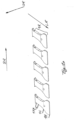
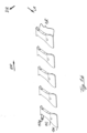
- the Fig. 1a ) and 1b ) show clip blanks 1R made of a shape memory material, in this case a superelastic NiTi compound, in order to produce clips 1 for brackets of an upper jaw ( Fig. 1a ) or brackets of a lower jaw ( Fig. 1b ).
- the clip blanks of the Fig. 1 Unfoldings of clip 1.
- Fig. 1a and 1b five clip blanks 1R are shown.
- the clip blanks 1R already have a holding support 1H, a guide section 1FA and between them a C-shaped section 1C, which are also present in the clip 1, as described below with reference to Fig. 2 described.
- a clip blank 1R of the Fig. 1a ie a clip blank 1R for an upper jaw bracket, has a length of 3.5 mm along the longitudinal direction LR, a thickness of 0.3 mm along the thickness direction DR and a width of 1.1 mm along the width direction BR.
- a clip blank 1 of the Fig. 1b ie clip blank 1 for a mandibular bracket, has a length of 3.5 mm along the longitudinal direction LR, a thickness of 0.3 mm along the thickness direction DR and a width of 0.9 mm along the width direction BR.
- the holding supports 1H of the clip blanks 1R of the Fig. 1a ) and 1b ) have a thickness of 0.3mm at the transition to the C-shape 1C and a thickness of 0.1mm at the free end, with the thickness decreasing linearly in the longitudinal direction.
- the width of the retaining supports 1H of the clip blanks 1R of the Fig. 1a ) and 1b ) is 2.6mm at the free end.
- a length of the retaining pads 1H of the clip blanks 1R of the Fig. 1a ) and 1b ) is 1.2 mm in the longitudinal direction LR.
- the clip blanks 1R are placed in the Fig. 2 shown form of clips 1 programmed.
- an engagement section 1E is created on the clip blank 1R, in this case a ball is fixed to it in order to fix a ligature or a rubber to it in later use. This results in the inventive clip 1 of the Fig. 2 .
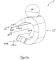
- Fig. 2a is a first perspective and in Fig. 2b ) a second perspective view, in Fig. 2c ) a side view and in Fig. 2d ) shows a bottom view of a clip 1 according to the invention.
- the guide section 1FA is formed on one in Fig. 2a ) lower end of the clip 1.
- This comprises two guide projections 1FV, which are formed on opposite sides of the guide section 1FA in the medial-lateral direction MLR and are opposite each other in the medial-lateral direction MLR.
- the guide projections 1FV each protrude 0.2mm in the medial-lateral direction MI,R, see in particular Fig. 2d ).
- the holding support 1H On one in Fig. 2a ) upper end of the clip 1, the holding support 1H is formed. As shown in particular in Fig. 2c ), the thickness of the support decreases towards the free end, as already Fig. 1 The free end of the support 1H is in Fig. 2c ) under Formation of a retention ramp 1HR. Both the decrease in thickness of the retention ramp 1H towards the free end and the retention ramp 1HR serve to facilitate sliding the retention ramp 1H onto a bracket or orthodontic wire, as described below.
- the holding support 1H extends significantly beyond the C-shaped section 1C on both sides in the medial-lateral direction MLR. This width of the holding support 1H serves to hold the orthodontic wire 5 in a slot, as described below.
- a clip ramp nose 1CN is formed at the lowest point of the underside of the holding support 1H.
- the clip ramp nose 1CN is formed as a projection running linearly in the medial-lateral direction MLR, which serves to lock onto a bracket body 3B in a release position in order to hold the clip 1 in the release position on the bracket body 3B, as described further below.
- Fig. 3a shows a perspective view, b) a rear view and c) a side view of a bracket body 3B with a slot 3S, wherein a section of an orthodontic wire 5 is arranged in the slot 3S.
- the wire 5 is arranged in the slot 3S almost without play, as is particularly evident in Fig. 3C shown. In this way, the voltage can be optimally transferred through the wire 5 to the slot 3S, since there is a good form fit between them.
- the bracket body 3 has two hooks 3H, in Fig. 3a ) below, in order to attach a ligature or rubber bands to them, for example.
- the in Fig. 3c The left side of the bracket body 3B, which runs linearly from top to bottom, is intended to accommodate a pad, which turns the bracket body 3B into a bracket. Typically, the pad is glued to a patient's tooth to firmly bond the bracket to the tooth.
- the bracket body 3B has a clip holder 3CA in its interior for holding the Fig. 2a ) lower end of the clip 1.
- the clip holder 3CA comprises two guide slots 3F opposite each other in the medial-lateral direction MLR.
- the guide slot has the shape of a truncated triangle:
- the wide end of the truncated triangle forms a free end and is used to thread the guide projection 1FV, in Fig. 3b right.
- the narrow end of the truncated triangle, in Fig. 3b is formed in an almost semicircular shape and thus forms a pivot bearing in order to pivotally accommodate the guide projection 1FV in it.
- the guide section 1FA is pivotally mounted in the bracket body 3B about an axis that runs in the medial-lateral direction through the narrow end of the guide slot 3F.
- bracket body ramp 3BR is formed, which is intended to facilitate sliding the retaining pad 1H of the clip 1 onto the bracket body 3B.
- each bracket body ramp 3BR a bracket body holding lug 3BN is formed for respective engagement with the respectively associated clip ramp lug 1CN of a clip 1 engaged with the bracket body 3B in order to hold the clip 1 in a release position on the bracket body 3B.
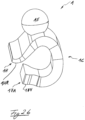
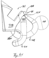
- the Fig. 4a ) and 4b ) show the clip 1 on the bracket body 3B in a release position in which a wire 5 can be arranged in the slot 3S.
- the two guide projections 1FV are in engagement with the respective narrow end of the guide slot 3F.
- the clip ramp nose 1CN is in engagement with the two bracket body retaining noses 3BN, as can be seen in particular in Fig. 4b ) is shown.
- Clip 1 is inserted into the Fig. 4 ) by first guiding the guide projections 1FV into the clip holder 3CA in such a way that the guide projections 1FV each engage in one of the two guide slots 3F, with the wide end of the triangular truncated member making insertion easier.
- the clip 1 is then pivoted around the two guide projections 1FV, which are arranged in the guide slot 3F, and the holding support 1H is pushed onto the bracket body ramp 3BR.
- both the holding support ramp 1HR and the thickness of the holding support 1H, which decreases towards the free end make it easier to push the holding support 1H onto the bracket body ramp 3BR.
- the retaining support 1H is pushed onto the bracket body ramp 3BR until the clip ramp nose 1CN is in engagement with the two bracket body retaining noses 3BN, whereby the two noses 1CN, 3BN lock together.
- the pivoting of the clip 1 and sliding of the holding support 1H onto the bracket body ramp can be carried out in a simple manner by bringing the finger of a practitioner into engagement with the engagement section 1E, i.e. the ball, of the clip 1.
- a finger of a practitioner can be brought into engagement with the engagement section 1E, ie the ball, of the clip 1 and the clip 1 can be further pivoted about the axis formed by the two guide projections 1FV in the guide slot 3F and thus push the holding support 1H in the direction of the wire 5 until the holding support 1H rests on the wire 5, as shown in particular in Fig. 5b ) is shown.
- the wire 5 optimally fills the slot 3 S, as described above. Furthermore, the holding support 1H rests on the wire 5 over the entire length of the bracket body 3B in the medial-lateral direction MLR, so that the clip 1 can exert a large holding force on the wire 5 in order to hold the wire 5 in the slot 3 S. Both helps to ensure that the wire 5 cannot tilt in the slot 3S. With a horizontal slot, there is no rotation of the wire in the slot. With a vertical slot, there is no angulation of the wire in the slot.
- the guide projections are opposite each other in the medial-lateral direction and/or advantageously protrude by 0.1 to 0.8 mm, in particular 0.2 mm.
- the bracket can be a lingual bracket or a buccal bracket.
Landscapes
- Health & Medical Sciences (AREA)
- Oral & Maxillofacial Surgery (AREA)
- Dentistry (AREA)
- Epidemiology (AREA)
- Life Sciences & Earth Sciences (AREA)
- Animal Behavior & Ethology (AREA)
- General Health & Medical Sciences (AREA)
- Public Health (AREA)
- Veterinary Medicine (AREA)
- Dental Tools And Instruments Or Auxiliary Dental Instruments (AREA)
Description
- Die Erfindung betrifft ein Bracket mit einem Clip.
- Für die kieferorthopädische Behandlung von Patienten mit festsitzenden Klammern werden Brackets auf die zu behandelnden Zähne des Patienten geklebt und durch einen kieferorthopädischen Draht miteinander verbunden. Die Brackets weisen ein Pad zur Verbindung mit dem Zahn und einen Bracketbody mit einem Slot auf, der den Drahtbogen aufnimmt, wobei ein Clip an dem Bracketbody vorgesehen ist, um den Drahtbogen in dem Slot zu halten.
- Die Brackets können Lingual- oder Bukkalbrackets sein, d.h. zur Anordnung auf der Lingual- bzw. Bukkalsseite der Zähne des Patienten vorgesehen sein.
- Zu Beginn einer kieferorthopädischen Behandlung werden häufig kieferorthopädische Drähte aus einem Formgedächtnismaterial in die Brackets eingesetzt, um eine "grobe" Ausrichtung der Zähne zu erreichen. Erst gegen Ende der kieferorthopädischen Behandlung werden bspw. Stahldrähte verwendet, um die Zähne möglichst genau in eine definierte Position zu bewegen. Der Drahtbogen wie auch der Clip können aus einem Formgedächtnismaterial bestehen.
- Zu den wichtigsten Formgedächtnismaterialien zählen Cu-Zn-X (X: Si, Sn, Al)- Legierungen und die intermetallische NiTi-Legierung (Nickelgehalt von ca. 55 gew.%), wobei die NiTi-Legierung aufgrund günstigerer Eigenschaften eine größere technologische Bedeutung erlangen konnte.
- Der Formgedächtnis-Effekt beruht auf einer thermoelastischen Martensitumwandlung, einer reversiblen, durch Scherung der Gitterebenen bedingten Phasenumwandlung. Die Abkühlung der Hochtemperatur-Phase, genannt Austenit, unter die legierungsspezifische Martensitstarttemperatur führt zu der Phasenumwandlung ohne Gestaltänderung und ohne irreversible plastische Verformung, wie es bei Stählen der Fall ist.
- Formgedächtnislegierungen lassen sich im martensitischen Zustand leicht verformen; die reversible Verformung kann bis zu 8% bei NiTi betragen. Diese Verformung ist bleibend, solange sich die Legierung im martensitischen Zustand befindet. Die Erwärmung oberhalb der legierungsspezifischen Austenitstarttemperatur führt dann zur Rückstellung der ursprünglichen Gestalt.
- Um ein kieferorthopädisches Bauteil aus einem Formgedächtnismaterial in eine Zielgeometrie zu überführen, wird dieser in einer speziellen Backform in die gewünschte Zielgeometrie gebracht und dann auf eine für das Formgedächtnismaterial spezifische Sprungtemperatur erhitzt. Anschließend wird das kieferorthopädische Bauteil wieder abgekühlt und in eine kieferorthopädische Apparatur eines Patienten, bspw. festsitzende Lingual- oder Bukkalbrackets, unter Verformung eingesetzt. In dem Mund des Patienten wird das elastisch verformte Bauteil, bspw. ein Drahtbogen oder ein Clip, wieder erwärmt und erinnert sich an seine Zielgeometrie, in die es sich dann zurückverformen will.
- Aus der
DE102017211867A1 ist eine Anordnung mit einem Bracket mit einem Pad und einem Bracketbody mit einem Slot zur Aufnahme eines kieferorthopädischen Drahtes sowie einen dem Bracket zugeordneten Clip aus einem Formgedächtnismaterial zum Verschließen und Freigeben des Slots des Brackets, um den kieferorthopädischen Draht in einer Schließstellung in dem Slot zu halten bzw. ihn in einer Öffnungsstellung zur Entnahme aus dem Slot frei zu geben. Ein erstes Ende des Clips ist ein Fixierende, das fest mit dem Bracket verbunden ist. Ein zweites Ende des Clips ist ein Freiende ist, das in der Öffnungsstellung an dem Bracket den Slot freigebend anliegt und in der Schließstellung an dem Bracket den Slot übergreifend anliegt. - Ein Nachteil des bekannten Clips ist, dass das Fixierende fest mit dem Brackebody zu verbunden ist, was in der Fertigung aufwändig ist. Ein weiterer Nachteil ist, dass der Drahtbogen im Slot zu viel Spiel hat bzw. der Clip den Drahtbogen nicht ausreichend fest hält, wodurch es bei einem horizontalen Slot einer Kippung des Drahtbogens im Slot und bei einem vertikalen Slot einer Angulation des Drahtbogens im Slot kommen kann.
- Aus der
CA 2 994 745 A1 ist ein Bracket mit einem Pad, einem Bracketbody und einem Slot in dem Bracketbody bekannt, wobei in dem Slot ein kieferorthopädischer Draht anordnbar ist. Um den Draht in dem Slot zu halten, ist ein Clip vorgesehen. Der Clip weist in der Querschnittsansicht im Wesentlichen eine C-Form auf, wobei ein Bracketbodyende des Clips in dem Bracketbody rein translatorisch verschieblich geführt ist und ein Drahtende des Clips in einer ersten Stellung den Slot übergreift, um den Draht in dem Slot zu halten, und in einer zweiten Stellung auf dem Bracketbody angeordnet ist, um den Draht zu wechseln. Das Bracketbodyende des Clips ist in einem Kanal in dem Bracketbody translatorisch verschieblich, wobei zu diesem Zweck ein Führungskanal in dem Bracketbody vorgesehen ist. Der Führungskanal ist entsprechend linear ausgebildet, um das Bracketbodyende des Clips rein translatorisch in dem Bracketbody zu führen. Nachteilig bei dieser Anordnung ist, dass sich Speisereste oder Ablagerungen von Speichel in dem Führungskanal ablagern können und diese die Führung des Bracketbodyendes des Clips in dem Führungskanal erschweren. - Die
US 2020/0375699 A1 zeigt eine festsitzende kieferorthopädische Apparatur, die Brackets aufweist, die an dem Zahn eines Patienten befestigt sind. Die Brackets weisen ein Pad, einen Bracketbody und einen Clip auf, wobei der Clip in der Querschnittsansicht eine C-Form aufweist. Ein Bodyende des Clips ist an dem Bracketbody fixiert und ein Freiende des Clips ist schwenkbar - in Richtung auf das fixe Bodyende zu und weg von diesem - angeordnet. In einem Inneren der C-Form, begrenzt von den beiden gegenüberliegenden Enden des Clips, kann ein Draht angeordnet werden. Der Draht kann sich innerhalb des Inneren der C-Form des Clips frei bewegen. Ein Slot zur definierten Führung des Drahts ist somit nicht vorgesehen. Der Clip, die Anordnung von dem Clip an dem Bracketbody und die Funktion des Clips sind somit nicht für das Halten des Drahts in einem Slot vorgesehen. - Die
US2015/0173859A1 , dieUS2018/0042700A1 , dieUS2017/0245963A1 , dieUS2013/0171579A1 und dieUS2012/0135364A1 zeigen jeweils Brackets mit einem Bracketbody, einem Pad und einem Slot, wobei in dem Bracketbody nahe dem Pad ein Clipführungskanal für einen Clip senkrecht zu dem Slot gebildet ist. Ein zugehöriger Clip weist einen linear verlaufenden Clipführungsabschnitt zur Aufnahme in dem linearen Clipführungskanal des Brackets auf und weist ein gegenüberliegendes Ende zum Übergreifen des Slots bzw. des darin angeordneten Drahtes auf. Übergreift der Clip den Slot, so steht das freie Ende des Clipführungsabschnitts über den Bracketbody vor: s.Fig. 1 in derUS2015/0173859A1 , Fig. 6, 10 und 13 in derUS2018/0042700A1 ,Fig. 5 in derUS2017/0245963A1 , Fig. 10 in derUS2013/0171579A1 undFig. 5 in derUS2012/0135364A1 . - Mit einer derartigen Anordnung sind mehrere Nachteile verbunden: Zum einen stört der Clipführungskanalabschnitt im Mundraum des Patienten, bspw. die Zunge. Zum anderen ist ein längs durch den Bracketbody verlaufender Clipführungskanal nachteilig, da sich in diesem Speisereste festsetzen und Verhärtungen, bspw. Verkalkungen bilden, so dass es häufig schwierig ist, den Clip nach einiger Zeit im Mund des Patienten von dem Bracket zu lösen. Die Verkrustungen in dem Clipführungskanal verhindern das Verschieben des Clips relativ zu dem Bracket.
- Aufgabe der vorliegenden Erfindung ist es daher, einen Clip für ein Bracket bereit zu stellen, der eine einfache Handhabung am Bracket erlaubt und den Drahtbogen gut im Slot hält.
- Die Aufgabe wird erfindungsgemäß durch einen Bracket mit einem C-förmigen Clip gelöst. Vorteilhaft weist der Bracketbody eine Bracketbodyrampe zum Aufschieben der Halteauflagerampe auf.
- Bevorzugt weist die Bracketbodyrampe eine Bracketbodyhaltenase zum Zusammenwirken mit einer Cliprampennase, insbesondere am Übergang Halteauflagenrampe zu C-Form des Clips, auf, um den Clip im geöffneten Zustand am Bracket zu halten, wobei in diesem Zustand der Führungsabschnitt des Clips in Eingriff mit der Clipaufnahme des Brackets steht, so dass der Clip durch seine C-Form elastisch am Bracket gehalten ist.
- Erfindungsgemäß setzt sich ein Ende der C-Form des Clips in einen Führungsabschnitt fort, der zum führenden Eingriff in eine Clipaufnahme des Brackets vorgesehen ist, um den Clip schwenkbar an dem Bracket zu halten, und sich das andere Ende der C-Form in eine sich in medial-lateral verbreiternde Halteauflage fortsetzt, um den kieferorthopädischen Draht im Slot zu halten.
- Mit Vorteil weist der Führungsabschnitt des Clips einen in medialer Richtung und einen in lateraler Richtung vorstehenden Führungsvorsprung auf, wobei sich die Führungsvorsprünge in medial-lateraler Richtung gegenüberliegen und / oder 0,1 bis 0,8mm, insbesondere 0,2mm, vorstehen.
- Bevorzugt verringert sich eine Dicke der Halteauflage des Clips in Richtung des freien Endes, insbesondere linear, um die Halteauflage elastisch zu bilden und ein Aufschieben der Halteauflage auf den kieferorthopädischen Draht bzw. das Bracket zu erleichtern.
- Vorteilhaft weist die Halteauflage des Clips eine in kaudaler Richtung gebogene Halteauflagenrampe auf, um ein Aufschieben der Halteauflage auf den kieferorthopädischen Draht bzw. das Bracket zu erleichtern.
- Bevorzugt weist die Halteauflage des Clips einen Eingriffabschnitt, insbesondere als Vorsprung gebildet, bspw. als Kugel oder Haken, auf, um ihn in Eingriff mit einem Gummi oder einer Ligatur zu bringen und/oder um das Ende des Clips, das die Halteauflage aufweist, von dem Bracket weg zu bewegen, insbesondere weg zu schieben, oder auf das Bracket hin zu bewegen, insbesondere auf das Bracket zu schieben, um so den Clip zu öffnen oder zu schließen, insbesondere per Hand.
- Vorteilhaft weist ein OK-Clip eine Länge von 2-8mm, insbesondere 3,5mm, und/oder eine Dicke von 0,2 bis 0,6mm, insbesondere von 0,3mm, und/oder eine Breite von 0,5 bis 2,5mm, insbesondere 1,1mm, und ein UK-Clip eine Länge von 2-8mm, insbesondere 3,5mm, und/oder eine Dicke von 0,2 bis 0,6mm, insbesondere von 0,3mm, und/oder eine Breite von 0,5 bis 2,5mm, insbesondere 0,9mm, auf.
- Bevorzugt weist die Halteauflage des Clips am Übergang in die C-Form eine Dicke von 0,2 bis 0,6mm und am freien Ende eine Dicke von 0,05 bis 0,3mm, insbesondere 0,1mm, und / oder am freien Ende eine Breite von 1 bis 8mm, insbesondere 2,6mm, und eine Länge von 0,5 bis 3mm, insbesondere 1,2mm, auf.
- Mit Vorteil besteht der Clip aus einem Formgedächtnismaterial, insbesondere aus einer superelastischen NiTi-Legierung.
- Weitere Merkmale, Einzelheiten und Vorzüge der Erfindung ergeben sich aus den Ansprüchen und der nachfolgenden Beschreibung bevorzugter Ausführungsformen sowie anhand der Zeichnung. Es zeigen:
- Fig. 1
- a) eine perspektivische Ansicht mehrerer Cliprohlinge zur Herstellung eines erfindungsgemäßen Clips für Lingualbrackets eines Oberkiefers und b) eine perspektivische Ansicht mehrerer Cliprohlinge zur Herstellung eines erfindungsgemäßen Clips für Lingualbrackets eines Unterkiefers,
- Fig. 2
- a) eine erste perspektivische Ansicht und b) eine zweite perspektivische Ansicht und c) eine Seitenansicht und d) eine Druntenansicht eines erfindungsgemäßen Clips,
- Fig. 3
- a) eine perspektivische Ansicht, b) eine Rückansicht und c) eine Seitenansicht eines Bracketbody mit einem Slot, wobei in dem Slot ein Abschnitt eines kieferorthopädischen Drahtes angeordnet ist,
- Fig. 4
- a) eine perspektivische Ansicht und b) eine Seitenansicht des Bracketbody der
Fig. 3 , wobei auf dem Bracketbody der Clip derFig. 2 angeordnet ist, wobei der Clip derart an dem Bracketbody angeordnet ist, dass der Slot frei gegeben ist (Freigabestellung), und - Fig. 5
- a) eine perspektivische Ansicht und b) eine Seitenansicht des Bracketbody der
Fig. 3 , wobei auf dem Bracketbody der Clip derFig. 2 angeordnet ist, wobei der Clip derart an dem Bracketbody angeordnet ist, dass der Slot nicht frei gegeben ist (Schließstellung). - Die
Fig. 1a ) und1b ) zeigen Cliprohlinge 1R aus einem Formgedächtnismaterial, vorliegend aus einer superelastischen NiTi-Verbindung, um aus diesen Clips 1 für Brackets eines Oberkiefers (Fig. 1a ) bzw. Brackets eines Unterkiefers (Fig. 1b ) herzustellen. Mit anderen Worten sind die Cliprohlinge derFig. 1 Abwicklungen des Clips 1. - In
Fig. 1a ) und1b ) sind jeweils fünf Cliprohlinge 1R gezeigt. Die Cliprohlinge 1R weisen bereits eine Halteauflage 1H, einen Führungsabschnitt 1FA und zwischen diesen einen C-Form-Abschnitt 1C auf, die auch in dem Clip 1 vorhanden sind, wie folgend unter Bezug aufFig. 2 beschrieben. - Ein Cliprohling 1R der
Fig. 1a ), d.h. ein Cliprohling 1R für ein Oberkieferbracket, weist eine Länge von 3,5mm entlang der Längsrichtung LR, eine Dicke von 0,3mm entlang der Dickenrichtung DR und eine Breite von 1,1mm entlang der Breitenrichtung BR auf. - Ein Cliprohling 1 der
Fig. 1b ), d.h. Cliprohling 1 für ein Unterkieferbracket, weist eine Länge von 3,5mm entlang der Längsrichtung LR, eine Dicke von 0,3mm entlang der Dickenrichtung DR und eine Breite von 0,9mm entlang der Breitenrichtung BR auf. - Die Halteauflagen 1H der Cliprohlinge 1R der
Fig. 1a ) und1b ) weisen am Übergang in die C-Form 1C eine Dicke von 0,3mm und am freien Ende eine Dicke von 0,1mm auf, wobei die Dicke in Längsrichtung linear abnimmt. Die Breite der Halteauflagen 1H der Cliprohlinge 1R derFig. 1a ) und1b ) beträgt am freien Ende 2,6mm. Eine Länge der Halteauflagen 1H der Cliprohlinge 1R derFig. 1a ) und1b ) beträgt 1,2mm in Längsrichtung LR. - In einer nicht dargestellten Backform werden die Cliprohlinge 1R der
Fig. 1a ) und1b ) gebacken. Dabei werden die Cliprohlinge 1R in die inFig. 2 gezeigte Form der Clips 1 programmiert. - Anschließend wird ein Eingriffabschnitt 1E an dem Cliprohling 1R geschaffen, vorliegend eine Kugel an diesen fixiert, um an diesem im späteren Einsatz bspw. eine Ligatur oder ein Gummi zu fixieren. Es ergibt sich der erfindungsgemäße Clip 1 der
Fig. 2 . - In
Fig. 2a ) ist eine erste perspektivische und inFig. 2b ) eine zweite perspektivische Ansicht, inFig. 2c ) eine Seitenansicht und inFig. 2d ) eine Druntenansicht eines erfindungsgemäßen Clips 1 gezeigt. - An einem in
Fig. 2a ) unteren Ende des Clip 1 ist der Führungsabschnitt 1FA gebildet. Dieser umfasst zwei Führungsvorsprünge 1FV, die in medial-lateraler-Richtung MLR gegenüberliegenden Seiten des Führungsabschnitts 1FA gebildet sind und sich in medial-lateraler-Richtung MLR gegenüberliegen. Die Führungsvorsprünge 1FV stehen in medial-lateraler-Richtung MI,R jeweils 0,2mm vor, s. insbesondereFig. 2d ). - An einem in
Fig. 2a ) oberen Ende des Clips 1 ist die Halteauflage 1H gebildet. Wie insbesondere inFig. 2c ) gezeigt, nimmt eine Dicke der Halteauflage zum freien Ende hin ab, wie bereits zuFig. 1 beschrieben. Das freie Ende des Halteauflage 1H ist inFig. 2c ) unter Bildung einer Halteauflagenrampe 1HR nach oben geschwungen. Sowohl die Abnahme der Dicke der Halteauflage 1H zum freien Ende hin als auch die Halteauflagenrampe 1HR dienen dazu, das Aufschieben der Halteauflage 1H auf ein Bracket oder einen kieferorthopädischen Draht zu erleichtern, wie weiter unten beschrieben. - Wie insbesondere in
Fig. 2d ) gezeigt, steht die Halteauflage 1H in medial-lateraler-Richtung MLR zu beiden Seiten des C-Form-Abschnitt 1C deutlich über diesen hinaus. Diese Breite der Halteauflage 1H dient dem Halten des kieferorthopädischen Drahts 5 in einem Slot, wie weiter unten beschrieben. - An der in
Fig. 2a ) tiefsten Stelle der Unterseite der Halteauflage 1H ist eine Cliprampennase 1CN gebildet. Die Cliprampennase 1CN ist als in medial-lateraler-Richtung MLR linienförmig verlaufender Vorsprung gebildet, der zum Verrasten an einem Bracketbody 3B in einer Freigabestellung dient, um den Clip 1 in der Freigabestellung an dem Bracketbody 3B zu halten, wie weiter unten beschrieben. -
Fig. 3a ) zeigt eine perspektivische Ansicht, b) eine Rückansicht und c) eine Seitenansicht eines Bracketbody 3B mit einem Slot 3S, wobei in dem Slot 3S ein Abschnitt eines kieferorthopädischen Drahtes 5 angeordnet ist. - Der Draht 5 ist in dem Slot 3S nahezu spielfrei angeordnet, wie insbesondere in
Fig. 3C gezeigt, Auf diese Weise kann die durch den Draht 5 auf den Slot 3S optimal übertragen werden, da ein guter Formschluss zwischen diesen vorliegt. - Der Bracketbody 3 weist zwei Hooks 3H, in
Fig. 3a ) unten, auf, um an diesen bspw. eine Ligatur oder Gummis zu befestigen. - Die in
Fig. 3c ) linear, von oben nach unten verlaufende, linke Seite des Bracketbody 3B ist vorgesehen, um an dieser ein Pad anzuordnen, wodurch aus dem Bracketbody 3B ein Bracket wird. Typischerweise wird das Pad auf einen Zahn eines Patienten geklebt, um das Bracket fest mit dem Zahn zu verbinden. - Wie in
Fig. 3b dargestellt, weist der Bracketbody 3B in seinem Innenraum eine Clipaufnahme 3CA zur Aufnahme des inFig. 2a ) unteren Ende des Clips 1 auf. Die Clipaufnahme 3CA umfasst dabei zwei sich in medial-lateraler-Richtung MLR gegenüberliegende Führungskulissen 3F. - Betrachtet man eine Führungskulisse 3F aus medial-lateraler-Richtung MLR, s. insbesondere
Fig. 3b ), so weist die Führungskulisse die Form eines Dreieckstumpf auf: Das breite Ende des Dreieckstumpfs bildet ein freies Ende und dient dem Einfädeln des Führungsvorsprungs 1FV, inFig. 3b rechts. Das schmale Ende des Dreieckstumpfs, inFig. 3b , ist nahezu halbkreisförmig gebildet und bildet dadurch ein Schwenklager, um den Führungsvorsprung 1FV in diesem schwenkbar aufzunehmen. Dadurch ist der Führungsabschnitt 1FA um eine Achse schwenkbar in dem Bracketbody 3B gelagert, die in medial-lateraler-Richtung durch das schmale Ende der Führungskulisse 3F verläuft. - Am in
Fig. 3a ) oberen Ende eines jeden Hooks 3H ist eine Bracketbodyrampe 3BR gebildet, die ein Aufschieben der Halteauflage 1H des Clips 1 auf den Bracketbody 3B erleichtern soll. - Ferner ist am in
Fig. 3a ) unteren Ende einer jeden Bracketbodyrampe 3BR eine Bracketbodyhaltenase 3BN zum jeweiligen Eingriff mit der jeweils zugeordneten Cliprampennase 1CN eines mit dem Bracketbody 3B in Eingriff stehenden Clips 1 gebildet, um den Clip 1 in einer Freigabestellung an dem Bracketbody 3B zu halten. - Die
Fig. 4a ) und4b ) zeigen den Clip 1 an dem Bracketbody 3B in einer Freigabestellung, in der ein Draht 5 in dem Slot 3S angeordnet werden kann. Die beiden Führungsvorsprünge 1FV sind in Eingriff mit dem jeweiligen schmalen Ende der Führungskulisse 3F. Die Cliprampennase 1CN ist in Eingriff mit den beiden Bracketbodyhaltenasen 3BN, wie insbesondere inFig. 4b ) dargestellt. - Der Clip 1 wird in die in
Fig. 4 ) gezeigte Freigabestellung gebracht, indem zunächst die Führungsvorsprünge 1FV derart in die Clipaufnahme 3CA geführt werden, dass die Führungsvorsprünge 1FV jeweils in eine der beiden Führungskulissen 3F greifen, wobei das breite Ende des Dreieckstumpfs das Einführen erleichtern. Folgend wird der Clip 1 um die beiden Führungsvorsprünge 1FV verschwenkt, die in der Führungskulisse 3F angeordnet sind, und die Halteauflage 1H wird auf die Bracketbodyrampe 3BR aufgeschoben. Wie bereits oben beschrieben, erleichtern sowohl die Halteauflagenrampe 1HR als auch die zum freien Ende hin abnehmende Dicke der Halteauflage 1H das Aufschieben der Halteauflage 1H auf die Bracketbodyrampe 3BR. Das Aufschieben der Halteauflage 1H auf die Bracketbodyrampe 3BR erfolgt so weit, bis die Cliprampennase 1CN in Eingriff steht mit den beiden Bracketbodyhaltenasen 3BN, wodurch die beiden Nasen 1CN, 3BN miteinander verrasten. Es kommt dadurch zu der inFig. 4 gezeigten Lage des Clips 1 am Bracketbody 3B, in der der Clip 1 stabil am Bracketbody 3B gehalten ist. - Das Verschwenken des Clip 1 und Aufschieben der Halteauflage 1H auf die Bracketbodyrampe kann in einfacher Weise dadurch erfolgen, dass der Finger eines Behandlers in Eingriff gebracht wird mit dem Eingriffabschnitt 1E, d.h. der Kugel, des Clips 1.
- Um den Clip 1 aus der in
Fig. 4 ) gezeigten Freigabestellung auf dem Bracketbody 3B in die inFig. 5a ) und5b ) gezeigte Schließstellung zu bewegen wird wie folgt vorgegangen:
Zunächst wird ein kieferorthopädischer Draht 5 in dem Slot 3 S des Bracketbody 3B angeordnet. - Folgend kann ein Finger eines Behandlers in Eingriff gebracht werden mit dem Eingriffabschnitt 1E, d.h. der Kugel, des Clips 1 und den Clip 1 weiter um die von den beiden Führungsvorsprüngen 1FV in der Führungskulisse 3F gebildete Achse verschwenken und somit die Halteauflage 1H in Richtung Draht 5 schieben, bis die Halteauflage 1H auf dem Draht 5 aufliegt, wie insbesondere in
Fig. 5b ) gezeigt. - Um den Clip 1 aus der in
Fig. 5 ) gezeigten Schließstellung wieder in die inFig. 4 ) gezeigte Freigabestellung zu überführen wird umgekehrt vorgegangen: Ein Finger eines Behandlers wird in Eingriff gebracht mit dem Eingriffabschnitt 1E, d.h. der Kugel, und die Halteauflage 1H wird von dem Draht 5 wieder in Richtung Bracketbodyhaltenase 3BN verschoben, bis die Cliprampennase 1CN in Eingriff ist mit der Bracketbodyhaltenase 3BN, wodurch die inFig. 4 ) gezeigte Freigabestellung erreicht ist. - An der Schließstellung der
Fig. 5 füllt der Draht 5 optimal den Slot 3 S aus, wie oben beschrieben. Ferner liegt die Halteauflage 1H fasst über die gesamte Länge des Bracketbody 3B in medial-lateraler-Richtung MLR auf dem Draht 5 auf, so dass der Clip 1 eine große Haltekraft auf den Draht 5 ausüben kann, um den Draht 5 in dem Slot 3 S zu halten. Beides trägt dazu bei, dass der Draht 5 in dem Slot 3S nicht kippen kann. Bei einem horizontalen Slot kommt es somit zu keiner Drehung des Drahts im Slot. Bei einem vertikalen Slot kommt es somit zu keiner Angulation des Drahts im Slot. - Vorteilhaft liegen sich die Führungsvorsprünge in medial-lateraler Richtung gegenüber und / oder stehen vorteilhaft 0,1 bis 0,8mm, insbesondere 0,2mm, vor.
- Das Bracket kann ein Lingualbracket oder ein Bukkalbracket sein.
-
- 1
- Clip
- 1C
- C-Form-Abschnitt
- 1CN
- Cliprampennase
- 1E
- Eingriffabschnitt
- 1FA
- Führungsabschnitt
- 1FV
- Führungsvorsprung
- 1H
- Halteauflage
- 1HR
- Halteauflagenrampe
- 1R
- Cliprohling
- 3B
- Bracketbody
- 3BR
- Bracketbodyrampe
- 3BN
- Bracketbodyhaltenase
- 3CA
- Clipaufnahme
- 3F
- Führungskulisse
- 3H
- Hook
- 3S
- Slot
- 5
- Draht
- BR
- Breitenrichtung
- DR
- Dickenrichtung
- LR
- Längsrichtung
- MLR
- medial-laterale-Richtung
Claims (10)
- Bracket (3) mit einem C-förmigen Clip (1), wobei sich ein Ende der C-Form des Clips (1) in einen Führungsabschnitt (1FA) fortsetzt, der zum führenden Eingriff in eine Clipaufnahme (3CA) des Brackets (3) vorgesehen ist, um den Clip (1) schwenkbar an dem Bracket (3) zu halten, und sich das andere Ende der C-Form in eine sich in medial-lateral verbreiternde Halteauflage (1H) fortsetzt, um den kieferorthopädischen Draht (5) im Slot (3S) zu halten, mit einem Pad zur Verbindung mit einem Zahn eines Patienten und einem Bracketbody (3B) mit einem Slot (3S) zur Aufnahme eines kieferorthopädischen Drahts (5), wobei eine Clipaufnahme (3CA) zur Aufnahme des Führungsabschnitts (1FA) des Clips (1) in dem Bracketbody (3B) gebildet ist, gekennzeichnet durch zwei sich in medial-lateraler-Richtung gegenüberliegende, im Bracketbody gebildete Führungskulissen (3F), um in der jeweiligen Führungskulisse (3F) den zugeordneten Führungsvorsprung (1FV) aufzunehmen, wobei die Führungskulisse (3F) aus medial-lateraler Richtung die Form eines Dreieckstumpf aufweist, so dass das breite Ende dem Einfädeln des Führungsvorsprungs und das schmale Ende dem Verschwenken des Clips um das schmale Ende dient.
- Bracket nach einem der vorangehenden Ansprüche, dadurch gekennzeichnet, dass der Bracketbody (3B) eine Bracketbodyrampe (3BR) zum Aufschieben der Halteauflagerampe (1HR) aufweist.
- Bracket nach dem vorangehenden Anspruch, dadurch gekennzeichnet, dass die Bracketbodyrampe (3BR) eine Bracketbodyhaltenase (3BN) zum Zusammenwirken mit einer Cliprampennase (1CN), insbesondere am Übergang Halteauflagenrampe zu C-Form des Clips, aufweist, um den Clip (1) im geöffneten Zustand am Bracket (3) zu halten, wobei in diesem Zustand der Führungsabschnitt (1FA) des Clips (1) in Eingriff mit der Clipaufnahme (3CA) des Brackets (3) steht, so dass der Clip durch seine C-Form elastisch am Bracket gehalten ist.
- Bracket nach einem der vorangehenden Ansprüche, dadurch gekennzeichnet, dass der Führungsabschnitt (1FA) des Clips (1) einen in medialer Richtung und einen in lateraler Richtung vorstehenden Führungsvorsprung (1FV) aufweist, wobei sich die Führungsvorsprünge (1FV) in medial-lateraler Richtung gegenüberliegen und / oder 0,1 bis 0,8mm, insbesondere 0,2mm, vorstehen.
- Bracket nach einem der vorangehenden Ansprüche, dadurch gekennzeichnet, dass sich eine Dicke der Halteauflage (1H) des Clips (1) in Richtung des freien Endes verringert, insbesondere linear, um die Halteauflage (1H) elastisch zu bilden und ein Aufschieben der Halteauflage (1H) auf den kieferorthopädischen Draht (5) bzw. das Bracket zu erleichtern.
- Bracket nach einem der vorangehenden Ansprüche, dadurch gekennzeichnet, dass die Halteauflage (1H) des Clips (1) eine in kaudaler Richtung gebogene Halteauflagenrampe (1HR) aufweist, um ein Aufschieben der Halteauflage (1H) auf den kieferorthopädischen Draht (5) bzw. das Bracket zu erleichtern.
- Bracket nach einem der vorangehenden Ansprüche, dadurch gekennzeichnet, dass Halteauflage (1H) des Clips (1) einen Eingriffabschnitt (1E), insbesondere als Vorsprung gebildet, bspw. als Kugel oder Haken, aufweist, um ihn in Eingriff mit einem Gummi oder einer Ligatur zu bringen und/oder um das Ende des Clips, das die Halteauflage (1H) aufweist, von dem Bracket (3) weg zu bewegen, insbesondere weg zu schieben, oder auf das Bracket (3) hin zu bewegen, insbesondere auf das Bracket (3) zu schieben, um so den Clip (1) zu öffnen oder zu schließen, insbesondere per Hand.
- Bracket nach einem der vorangehenden Ansprüche, dadurch gekennzeichnet, dass ein OK-Clip (1) eine Länge von 2-8mm, insbesondere 3,5mm, und/oder eine Dicke von 0,2 bis 0,6mm, insbesondere von 0,3mm, und/oder eine Breite von 0,5 bis 2,5mm, insbesondere 1,1mm, und ein UK-Clip eine Länge von 2-8mm, insbesondere 3,5mm, und/oder eine Dicke von 0,2 bis 0,6mm, insbesondere von 0,3mm, und/oder eine Breite von 0,5 bis 2,5mm, insbesondere 0,9mm, aufweist.
- Bracket nach einem der vorangehenden Ansprüche, dadurch gekennzeichnet, dass die Halteauflage (1H) des Clips (1) am Übergang in die C-Form eine Dicke von 0,2 bis 0,6mm und am freien Ende eine Dicke von 0,05 bis 0,3mm, insbesondere 0,1mm, und / oder am freien Ende eine Breite von 1 bis 8mm, insbesondere 2,6mm, und eine Länge von 0,5 bis 3mm, insbesondere 1,2mm, aufweist.
- Bracket nach einem der vorangehenden Ansprüche, dadurch gekennzeichnet, dass der Clip (1) aus einem Formgedächtnismaterial, insbesondere aus einer superelastischen NiTi-Legierung, besteht.
Applications Claiming Priority (1)
| Application Number | Priority Date | Filing Date | Title |
|---|---|---|---|
| DE102020214586.5A DE102020214586A1 (de) | 2020-11-19 | 2020-11-19 | Clip für ein kieferorthopädisches Bracket |
Publications (3)
| Publication Number | Publication Date |
|---|---|
| EP4005528A1 EP4005528A1 (de) | 2022-06-01 |
| EP4005528B1 true EP4005528B1 (de) | 2024-10-09 |
| EP4005528B8 EP4005528B8 (de) | 2025-03-12 |
Family
ID=78516588
Family Applications (1)
| Application Number | Title | Priority Date | Filing Date |
|---|---|---|---|
| EP21206149.3A Active EP4005528B8 (de) | 2020-11-19 | 2021-11-03 | Clip für ein kieferorthopädisches bracket |
Country Status (4)
| Country | Link |
|---|---|
| EP (1) | EP4005528B8 (de) |
| DE (1) | DE102020214586A1 (de) |
| ES (1) | ES3000063T3 (de) |
| PL (1) | PL4005528T3 (de) |
Family Cites Families (8)
| Publication number | Priority date | Publication date | Assignee | Title |
|---|---|---|---|---|
| EP2387370A4 (de) * | 2009-01-16 | 2015-08-26 | Ormco Corp | Zahnärztliche klammer und verfahren zur korrektur von fehlstellungen der zähne |
| US9901423B2 (en) * | 2010-09-17 | 2018-02-27 | Tomy Incorporated | Orthodontic bracket |
| US20120135364A1 (en) * | 2010-11-22 | 2012-05-31 | American Orthodontics, Inc., a Wisconsin Corporation | Orthodontic bracket with auxiliary slot |
| US20150173859A1 (en) * | 2012-07-02 | 2015-06-25 | 3M Innovative Properties Company | Orthodontic appliance with ligating feature |
| US9770310B2 (en) * | 2016-02-25 | 2017-09-26 | Pbd, Patent & Business Development Ag | Orthodontic self-ligating bracket |
| DE102017211867A1 (de) | 2017-07-11 | 2019-01-17 | Dw Lingual Systems Gmbh | Anordnung mit einem Bracket und einem Clip |
| CA2994745A1 (en) | 2018-02-09 | 2019-08-09 | Spartan Orthodontics Inc. | Low profile orthodontic bracket |
| KR20220004150A (ko) | 2019-05-02 | 2022-01-11 | 브리우스 테크놀로지스 인코퍼레이티드 | 치과 기기 및 관련 제작 방법 |
-
2020
- 2020-11-19 DE DE102020214586.5A patent/DE102020214586A1/de active Pending
-
2021
- 2021-11-03 PL PL21206149.3T patent/PL4005528T3/pl unknown
- 2021-11-03 ES ES21206149T patent/ES3000063T3/es active Active
- 2021-11-03 EP EP21206149.3A patent/EP4005528B8/de active Active
Also Published As
| Publication number | Publication date |
|---|---|
| EP4005528B8 (de) | 2025-03-12 |
| PL4005528T3 (pl) | 2025-06-16 |
| EP4005528A1 (de) | 2022-06-01 |
| DE102020214586A1 (de) | 2022-05-19 |
| ES3000063T3 (en) | 2025-02-27 |
Similar Documents
| Publication | Publication Date | Title |
|---|---|---|
| DE60035392T2 (de) | Kieferorthopädische zahnspange und zugehöriges werkzeug | |
| DE3341259C2 (de) | Orthodonte Klammer | |
| DE69827672T2 (de) | Teleskopartiges intraorales kraftelement | |
| EP2046234B1 (de) | Bracket mit einem pad | |
| DE60224090T2 (de) | Orthodontische vorrichtung mit lingualer halterille | |
| DE19603889C2 (de) | Chirurgisches Anlegegerät | |
| DE19624654C2 (de) | Federnd expandierendes Orthodontiegerät | |
| DE202008018568U1 (de) | Selbstligierende orthodontische Klammer und Vorrichtung zur ihrer Abgabe | |
| DE60307127T2 (de) | Backenzahneinrichtung zur kiefeorthopädischen therapie | |
| EP1961396A1 (de) | Kieferorthopädisches Bracket mit elastischer Aufnahme- und Befestigungsvorrichtung | |
| DE10112800A1 (de) | Selbstanbindende kieferorthopädische Klammer | |
| CH619611A5 (de) | ||
| DE9301873U1 (de) | Dreikanalige orthodontische buccale Stütze | |
| DE2252876B2 (de) | Kiefernorthopädische Haltevorrichtung | |
| DE212014000061U1 (de) | Statische selbstbindende orthodontische Zahnspange | |
| DE112004000371T5 (de) | Orthodontische Brackets mit lang gestrecktem Filmgelenk | |
| DE102014104152A1 (de) | Kieferorthopädisches zubehör | |
| DE102005019273A1 (de) | Kieferorthopädische Molarbrackets mit schwenkbarer Bracketüberdeckung | |
| EP4005528B1 (de) | Clip für ein kieferorthopädisches bracket | |
| DE2163292A1 (de) | Orthodontische Vorrichtung | |
| DE10346489B4 (de) | Vorrichtung zur Korrektur der Stellung von Ober- und Unterkiefer zueinander und/oder Platzgewinnung im Oberkiefer | |
| DE2357573C2 (de) | Zahnregulierungsklammer | |
| DE202007007461U1 (de) | Positionierungshalter für eine kieferorthopädische Vorrichtung | |
| CH635506A5 (de) | Orthodontische klammer. | |
| DE102013013098B4 (de) | Orthodontisches Bracket zur Befestigung an einer Innenseite eines Zahns |
Legal Events
| Date | Code | Title | Description |
|---|---|---|---|
| PUAI | Public reference made under article 153(3) epc to a published international application that has entered the european phase |
Free format text: ORIGINAL CODE: 0009012 |
|
| STAA | Information on the status of an ep patent application or granted ep patent |
Free format text: STATUS: THE APPLICATION HAS BEEN PUBLISHED |
|
| AK | Designated contracting states |
Kind code of ref document: A1 Designated state(s): AL AT BE BG CH CY CZ DE DK EE ES FI FR GB GR HR HU IE IS IT LI LT LU LV MC MK MT NL NO PL PT RO RS SE SI SK SM TR |
|
| RAP1 | Party data changed (applicant data changed or rights of an application transferred) |
Owner name: DW LINGUAL SYSTEMS GMH |
|
| RIN1 | Information on inventor provided before grant (corrected) |
Inventor name: WIECHMANN, DIRK |
|
| STAA | Information on the status of an ep patent application or granted ep patent |
Free format text: STATUS: REQUEST FOR EXAMINATION WAS MADE |
|
| 17P | Request for examination filed |
Effective date: 20221104 |
|
| RBV | Designated contracting states (corrected) |
Designated state(s): AL AT BE BG CH CY CZ DE DK EE ES FI FR GB GR HR HU IE IS IT LI LT LU LV MC MK MT NL NO PL PT RO RS SE SI SK SM TR |
|
| P01 | Opt-out of the competence of the unified patent court (upc) registered |
Effective date: 20230530 |
|
| STAA | Information on the status of an ep patent application or granted ep patent |
Free format text: STATUS: EXAMINATION IS IN PROGRESS |
|
| 17Q | First examination report despatched |
Effective date: 20231116 |
|
| GRAP | Despatch of communication of intention to grant a patent |
Free format text: ORIGINAL CODE: EPIDOSNIGR1 |
|
| STAA | Information on the status of an ep patent application or granted ep patent |
Free format text: STATUS: GRANT OF PATENT IS INTENDED |
|
| INTG | Intention to grant announced |
Effective date: 20240502 |
|
| GRAS | Grant fee paid |
Free format text: ORIGINAL CODE: EPIDOSNIGR3 |
|
| GRAA | (expected) grant |
Free format text: ORIGINAL CODE: 0009210 |
|
| STAA | Information on the status of an ep patent application or granted ep patent |
Free format text: STATUS: THE PATENT HAS BEEN GRANTED |
|
| AK | Designated contracting states |
Kind code of ref document: B1 Designated state(s): AL AT BE BG CH CY CZ DE DK EE ES FI FR GB GR HR HU IE IS IT LI LT LU LV MC MK MT NL NO PL PT RO RS SE SI SK SM TR |
|
| REG | Reference to a national code |
Ref country code: CH Ref legal event code: EP |
|
| REG | Reference to a national code |
Ref country code: DE Ref legal event code: R096 Ref document number: 502021005413 Country of ref document: DE |
|
| REG | Reference to a national code |
Ref country code: IE Ref legal event code: FG4D Free format text: LANGUAGE OF EP DOCUMENT: GERMAN |
|
| PGFP | Annual fee paid to national office [announced via postgrant information from national office to epo] |
Ref country code: DE Payment date: 20241120 Year of fee payment: 4 |
|
| PGFP | Annual fee paid to national office [announced via postgrant information from national office to epo] |
Ref country code: FR Payment date: 20241128 Year of fee payment: 4 |
|
| REG | Reference to a national code |
Ref country code: LT Ref legal event code: MG9D |
|
| PGFP | Annual fee paid to national office [announced via postgrant information from national office to epo] |
Ref country code: IT Payment date: 20241130 Year of fee payment: 4 Ref country code: ES Payment date: 20241227 Year of fee payment: 4 |
|
| PGFP | Annual fee paid to national office [announced via postgrant information from national office to epo] |
Ref country code: CH Payment date: 20241230 Year of fee payment: 4 |
|
| REG | Reference to a national code |
Ref country code: NL Ref legal event code: MP Effective date: 20241009 |
|
| REG | Reference to a national code |
Ref country code: CH Ref legal event code: PK Free format text: BERICHTIGUNG B8 |
|
| REG | Reference to a national code |
Ref country code: ES Ref legal event code: FG2A Ref document number: 3000063 Country of ref document: ES Kind code of ref document: T3 Effective date: 20250227 |
|
| RAP4 | Party data changed (patent owner data changed or rights of a patent transferred) |
Owner name: DW LINGUAL SYSTEMS GMBH |
|
| PG25 | Lapsed in a contracting state [announced via postgrant information from national office to epo] |
Ref country code: NL Free format text: LAPSE BECAUSE OF FAILURE TO SUBMIT A TRANSLATION OF THE DESCRIPTION OR TO PAY THE FEE WITHIN THE PRESCRIBED TIME-LIMIT Effective date: 20241009 |
|
| PG25 | Lapsed in a contracting state [announced via postgrant information from national office to epo] |
Ref country code: NL Free format text: LAPSE BECAUSE OF FAILURE TO SUBMIT A TRANSLATION OF THE DESCRIPTION OR TO PAY THE FEE WITHIN THE PRESCRIBED TIME-LIMIT Effective date: 20241009 |
|
| PG25 | Lapsed in a contracting state [announced via postgrant information from national office to epo] |
Ref country code: HR Free format text: LAPSE BECAUSE OF FAILURE TO SUBMIT A TRANSLATION OF THE DESCRIPTION OR TO PAY THE FEE WITHIN THE PRESCRIBED TIME-LIMIT Effective date: 20241009 Ref country code: IS Free format text: LAPSE BECAUSE OF FAILURE TO SUBMIT A TRANSLATION OF THE DESCRIPTION OR TO PAY THE FEE WITHIN THE PRESCRIBED TIME-LIMIT Effective date: 20250209 Ref country code: PT Free format text: LAPSE BECAUSE OF FAILURE TO SUBMIT A TRANSLATION OF THE DESCRIPTION OR TO PAY THE FEE WITHIN THE PRESCRIBED TIME-LIMIT Effective date: 20250210 |
|
| PG25 | Lapsed in a contracting state [announced via postgrant information from national office to epo] |
Ref country code: FI Free format text: LAPSE BECAUSE OF FAILURE TO SUBMIT A TRANSLATION OF THE DESCRIPTION OR TO PAY THE FEE WITHIN THE PRESCRIBED TIME-LIMIT Effective date: 20241009 |
|
| PG25 | Lapsed in a contracting state [announced via postgrant information from national office to epo] |
Ref country code: BG Free format text: LAPSE BECAUSE OF FAILURE TO SUBMIT A TRANSLATION OF THE DESCRIPTION OR TO PAY THE FEE WITHIN THE PRESCRIBED TIME-LIMIT Effective date: 20241009 |
|
| PG25 | Lapsed in a contracting state [announced via postgrant information from national office to epo] |
Ref country code: NO Free format text: LAPSE BECAUSE OF FAILURE TO SUBMIT A TRANSLATION OF THE DESCRIPTION OR TO PAY THE FEE WITHIN THE PRESCRIBED TIME-LIMIT Effective date: 20250109 |
|
| PG25 | Lapsed in a contracting state [announced via postgrant information from national office to epo] |
Ref country code: LV Free format text: LAPSE BECAUSE OF FAILURE TO SUBMIT A TRANSLATION OF THE DESCRIPTION OR TO PAY THE FEE WITHIN THE PRESCRIBED TIME-LIMIT Effective date: 20241009 Ref country code: GR Free format text: LAPSE BECAUSE OF FAILURE TO SUBMIT A TRANSLATION OF THE DESCRIPTION OR TO PAY THE FEE WITHIN THE PRESCRIBED TIME-LIMIT Effective date: 20250110 |
|
| PG25 | Lapsed in a contracting state [announced via postgrant information from national office to epo] |
Ref country code: RS Free format text: LAPSE BECAUSE OF FAILURE TO SUBMIT A TRANSLATION OF THE DESCRIPTION OR TO PAY THE FEE WITHIN THE PRESCRIBED TIME-LIMIT Effective date: 20250109 |
|
| PGFP | Annual fee paid to national office [announced via postgrant information from national office to epo] |
Ref country code: TR Payment date: 20241227 Year of fee payment: 4 |
|
| PG25 | Lapsed in a contracting state [announced via postgrant information from national office to epo] |
Ref country code: SM Free format text: LAPSE BECAUSE OF FAILURE TO SUBMIT A TRANSLATION OF THE DESCRIPTION OR TO PAY THE FEE WITHIN THE PRESCRIBED TIME-LIMIT Effective date: 20241009 |
|
| PG25 | Lapsed in a contracting state [announced via postgrant information from national office to epo] |
Ref country code: MC Free format text: LAPSE BECAUSE OF FAILURE TO SUBMIT A TRANSLATION OF THE DESCRIPTION OR TO PAY THE FEE WITHIN THE PRESCRIBED TIME-LIMIT Effective date: 20241009 |
|
| PGFP | Annual fee paid to national office [announced via postgrant information from national office to epo] |
Ref country code: PL Payment date: 20241203 Year of fee payment: 4 |
|
| PG25 | Lapsed in a contracting state [announced via postgrant information from national office to epo] |
Ref country code: DK Free format text: LAPSE BECAUSE OF FAILURE TO SUBMIT A TRANSLATION OF THE DESCRIPTION OR TO PAY THE FEE WITHIN THE PRESCRIBED TIME-LIMIT Effective date: 20241009 |
|
| REG | Reference to a national code |
Ref country code: DE Ref legal event code: R097 Ref document number: 502021005413 Country of ref document: DE |
|
| PG25 | Lapsed in a contracting state [announced via postgrant information from national office to epo] |
Ref country code: LU Free format text: LAPSE BECAUSE OF NON-PAYMENT OF DUE FEES Effective date: 20241103 |
|
| PG25 | Lapsed in a contracting state [announced via postgrant information from national office to epo] |
Ref country code: RO Free format text: LAPSE BECAUSE OF FAILURE TO SUBMIT A TRANSLATION OF THE DESCRIPTION OR TO PAY THE FEE WITHIN THE PRESCRIBED TIME-LIMIT Effective date: 20241009 |
|
| PG25 | Lapsed in a contracting state [announced via postgrant information from national office to epo] |
Ref country code: SK Free format text: LAPSE BECAUSE OF FAILURE TO SUBMIT A TRANSLATION OF THE DESCRIPTION OR TO PAY THE FEE WITHIN THE PRESCRIBED TIME-LIMIT Effective date: 20241009 |
|
| PG25 | Lapsed in a contracting state [announced via postgrant information from national office to epo] |
Ref country code: CZ Free format text: LAPSE BECAUSE OF FAILURE TO SUBMIT A TRANSLATION OF THE DESCRIPTION OR TO PAY THE FEE WITHIN THE PRESCRIBED TIME-LIMIT Effective date: 20241009 |
|
| PLBE | No opposition filed within time limit |
Free format text: ORIGINAL CODE: 0009261 |
|
| STAA | Information on the status of an ep patent application or granted ep patent |
Free format text: STATUS: NO OPPOSITION FILED WITHIN TIME LIMIT |
|
| REG | Reference to a national code |
Ref country code: BE Ref legal event code: MM Effective date: 20241130 |
|
| PG25 | Lapsed in a contracting state [announced via postgrant information from national office to epo] |
Ref country code: SE Free format text: LAPSE BECAUSE OF FAILURE TO SUBMIT A TRANSLATION OF THE DESCRIPTION OR TO PAY THE FEE WITHIN THE PRESCRIBED TIME-LIMIT Effective date: 20241009 |
|
| 26N | No opposition filed |
Effective date: 20250710 |
|
| PG25 | Lapsed in a contracting state [announced via postgrant information from national office to epo] |
Ref country code: BE Free format text: LAPSE BECAUSE OF NON-PAYMENT OF DUE FEES Effective date: 20241130 |
|
| PG25 | Lapsed in a contracting state [announced via postgrant information from national office to epo] |
Ref country code: IE Free format text: LAPSE BECAUSE OF NON-PAYMENT OF DUE FEES Effective date: 20241103 |
|
| REG | Reference to a national code |
Ref country code: CH Ref legal event code: U11 Free format text: ST27 STATUS EVENT CODE: U-0-0-U10-U11 (AS PROVIDED BY THE NATIONAL OFFICE) Effective date: 20251201 |