EP4004498B1 - Messgerät zum erfassen einer prozessgrösse in einem behälter - Google Patents
Messgerät zum erfassen einer prozessgrösse in einem behälter Download PDFInfo
- Publication number
- EP4004498B1 EP4004498B1 EP19752658.5A EP19752658A EP4004498B1 EP 4004498 B1 EP4004498 B1 EP 4004498B1 EP 19752658 A EP19752658 A EP 19752658A EP 4004498 B1 EP4004498 B1 EP 4004498B1
- Authority
- EP
- European Patent Office
- Prior art keywords
- container
- measuring device
- housing
- sensor
- thread
- Prior art date
- Legal status (The legal status is an assumption and is not a legal conclusion. Google has not performed a legal analysis and makes no representation as to the accuracy of the status listed.)
- Active
Links
Images


Classifications
-
- G—PHYSICS
- G01—MEASURING; TESTING
- G01F—MEASURING VOLUME, VOLUME FLOW, MASS FLOW OR LIQUID LEVEL; METERING BY VOLUME
- G01F23/00—Indicating or measuring liquid level or level of fluent solid material, e.g. indicating in terms of volume or indicating by means of an alarm
- G01F23/22—Indicating or measuring liquid level or level of fluent solid material, e.g. indicating in terms of volume or indicating by means of an alarm by measuring physical variables, other than linear dimensions, pressure or weight, dependent on the level to be measured, e.g. by difference of heat transfer of steam or water
- G01F23/28—Indicating or measuring liquid level or level of fluent solid material, e.g. indicating in terms of volume or indicating by means of an alarm by measuring physical variables, other than linear dimensions, pressure or weight, dependent on the level to be measured, e.g. by difference of heat transfer of steam or water by measuring the variations of parameters of electromagnetic or acoustic waves applied directly to the liquid or fluent solid material
- G01F23/284—Electromagnetic waves
-
- G—PHYSICS
- G01—MEASURING; TESTING
- G01F—MEASURING VOLUME, VOLUME FLOW, MASS FLOW OR LIQUID LEVEL; METERING BY VOLUME
- G01F23/00—Indicating or measuring liquid level or level of fluent solid material, e.g. indicating in terms of volume or indicating by means of an alarm
- G01F23/22—Indicating or measuring liquid level or level of fluent solid material, e.g. indicating in terms of volume or indicating by means of an alarm by measuring physical variables, other than linear dimensions, pressure or weight, dependent on the level to be measured, e.g. by difference of heat transfer of steam or water
- G01F23/28—Indicating or measuring liquid level or level of fluent solid material, e.g. indicating in terms of volume or indicating by means of an alarm by measuring physical variables, other than linear dimensions, pressure or weight, dependent on the level to be measured, e.g. by difference of heat transfer of steam or water by measuring the variations of parameters of electromagnetic or acoustic waves applied directly to the liquid or fluent solid material
- G01F23/296—Acoustic waves
-
- G—PHYSICS
- G01—MEASURING; TESTING
- G01F—MEASURING VOLUME, VOLUME FLOW, MASS FLOW OR LIQUID LEVEL; METERING BY VOLUME
- G01F23/00—Indicating or measuring liquid level or level of fluent solid material, e.g. indicating in terms of volume or indicating by means of an alarm
- G01F23/80—Arrangements for signal processing
- G01F23/802—Particular electronic circuits for digital processing equipment
- G01F23/804—Particular electronic circuits for digital processing equipment containing circuits handling parameters other than liquid level
-
- G—PHYSICS
- G01—MEASURING; TESTING
- G01S—RADIO DIRECTION-FINDING; RADIO NAVIGATION; DETERMINING DISTANCE OR VELOCITY BY USE OF RADIO WAVES; LOCATING OR PRESENCE-DETECTING BY USE OF THE REFLECTION OR RERADIATION OF RADIO WAVES; ANALOGOUS ARRANGEMENTS USING OTHER WAVES
- G01S13/00—Systems using the reflection or reradiation of radio waves, e.g. radar systems; Analogous systems using reflection or reradiation of waves whose nature or wavelength is irrelevant or unspecified
- G01S13/88—Radar or analogous systems specially adapted for specific applications
-
- G—PHYSICS
- G01—MEASURING; TESTING
- G01S—RADIO DIRECTION-FINDING; RADIO NAVIGATION; DETERMINING DISTANCE OR VELOCITY BY USE OF RADIO WAVES; LOCATING OR PRESENCE-DETECTING BY USE OF THE REFLECTION OR RERADIATION OF RADIO WAVES; ANALOGOUS ARRANGEMENTS USING OTHER WAVES
- G01S15/00—Systems using the reflection or reradiation of acoustic waves, e.g. sonar systems
- G01S15/88—Sonar systems specially adapted for specific applications
-
- H—ELECTRICITY
- H01—ELECTRIC ELEMENTS
- H01Q—ANTENNAS, i.e. RADIO AERIALS
- H01Q1/00—Details of, or arrangements associated with, antennas
- H01Q1/12—Supports; Mounting means
- H01Q1/22—Supports; Mounting means by structural association with other equipment or articles
- H01Q1/225—Supports; Mounting means by structural association with other equipment or articles used in level-measurement devices, e.g. for level gauge measurement
-
- G—PHYSICS
- G01—MEASURING; TESTING
- G01S—RADIO DIRECTION-FINDING; RADIO NAVIGATION; DETERMINING DISTANCE OR VELOCITY BY USE OF RADIO WAVES; LOCATING OR PRESENCE-DETECTING BY USE OF THE REFLECTION OR RERADIATION OF RADIO WAVES; ANALOGOUS ARRANGEMENTS USING OTHER WAVES
- G01S7/00—Details of systems according to groups G01S13/00, G01S15/00, G01S17/00
- G01S7/02—Details of systems according to groups G01S13/00, G01S15/00, G01S17/00 of systems according to group G01S13/00
- G01S7/027—Constructional details of housings, e.g. form, type, material or ruggedness
-
- H—ELECTRICITY
- H01—ELECTRIC ELEMENTS
- H01Q—ANTENNAS, i.e. RADIO AERIALS
- H01Q1/00—Details of, or arrangements associated with, antennas
- H01Q1/44—Details of, or arrangements associated with, antennas using equipment having another main function to serve additionally as an antenna, e.g. means for giving an antenna an aesthetic aspect
-
- H—ELECTRICITY
- H01—ELECTRIC ELEMENTS
- H01Q—ANTENNAS, i.e. RADIO AERIALS
- H01Q19/00—Combinations of primary active antenna elements and units with secondary devices, e.g. with quasi-optical devices, for giving the antenna a desired directional characteristic
- H01Q19/06—Combinations of primary active antenna elements and units with secondary devices, e.g. with quasi-optical devices, for giving the antenna a desired directional characteristic using refracting or diffracting devices, e.g. lens
- H01Q19/08—Combinations of primary active antenna elements and units with secondary devices, e.g. with quasi-optical devices, for giving the antenna a desired directional characteristic using refracting or diffracting devices, e.g. lens for modifying the radiation pattern of a radiating horn in which it is located
Definitions
- the invention relates to a measuring device for detecting a process variable in a container and to a container with a container opening and a measuring device arranged therein.
- Sensors that record data or properties of process variables or substances within a container are usually mounted on the container outside the container, or they are mounted inside the container and the container is sealed after assembly so that the filling medium cannot escape from the container. Therefore, they are installed from the outside using a screw thread, for example, and the electronic unit is located outside the container, while the sensor (antenna) is inside the container. There are also measuring devices in which, for example, only an antenna is located inside the container.
- measuring instruments or sensors that are located in a sealed container are cannot be easily assembled or disassembled.
- Sensors that are located outside the container or partially inside the container have the disadvantage that the containers cannot be assembled in a space-saving manner, for example they cannot be stacked on top of each other.
- IBCs intermediate bulk containers
- the WO 03/085365 A1 describes a radar level measuring device for contactless measurement of a level in a container, which has electronics and antenna in one housing.
- the US 6 363 784 B1 describes a level detector having a light emitter, a light receiver, an electrical circuit, and a glass housing that essentially encapsulates the light receiver, light emitter, and electrical circuit to protect the detector from hazardous environments.
- the object of the invention is therefore to find a measuring device for a container and a container with a measuring device, which are designed in such a way that the containers can be set up in a space-efficient manner and the measuring device can still be mounted flexibly.
- a measuring device for detecting a process variable in a container comprising an electronic unit with a housing and a sealing arrangement adjacent to the housing.
- the measuring device is designed to be arranged in a container opening.
- the sealing arrangement is designed to seal the container opening and the electronic unit is arranged below a geometric plane of the sealing arrangement when the measuring device is in the container opening, i.e. when the measuring device is mounted.
- a measuring device is understood to mean an arrangement that has a unit for the physical recording of the process variable, e.g. a physical sensor or a generator-receiver arrangement for e.g. ultrasonic waves or Radar, as well as an electronic unit that at least provides the electrical energy supply and, depending on the application, electronically processes the recorded process variable and makes it available as digital data.
- the electronic elements that can be used for this purpose such as voltage regulators, voltage converters, protective circuits, analog-digital converters, filters, amplifiers, microprocessors, memory modules, signal generators, vibration generators, radiators, piezo converters, etc., are known to those skilled in the art.
- the measuring device can, for example, determine substances or components of a medium, such as a liquid or a gas in a container, or record a temperature, a pressure or a fill level.
- the measuring device has an electronic unit for operating the sensor and for providing the measurement data, which is mounted in a housing.
- the housing accommodates the electronic unit, protects it from environmental influences and is used in particular for mounting on or in the container.
- the housing has, for example, an external thread, so that it can be screwed into a container opening with a corresponding thread up to, for example, a protruding support surface, e.g. a circumferential projection on the end of the housing remaining outside the container.
- the height of the protruding part can, for example, be selected so that it does not exceed a defined edge height on the top of the container, so that the containers can be stacked.
- a sealing arrangement e.g. a sealing ring, encloses the threaded shaft at the end of the thread.
- the shaft part that is enclosed by the sealing arrangement can be threadless.
- the sealing arrangement consists of a sealing ring which, in the assembled state of the measuring device, is positioned along the circular container opening. runs and seals the container.
- the plane of the sealing arrangement is the circular plane of the sealing ring that is in contact with the circular opening.
- the term “below” is to be seen in the reference system of the measuring device, where when mounted, the direction “downwards” points perpendicular to the container opening into the container. If the sensor is mounted on the container lid, this means that the part "below” a geometric plane of the sealing arrangement is inside the container.
- the plane of the side container opening is perpendicular to the container base or container lid, and “below” this plane refers to the part of the measuring device that protrudes into the container.
- This part houses the electronics unit. This is therefore located in the area of the housing that is surrounded by the thread and is inside the container when screwed in, with "inside” being defined by the plane of the sealing ring.
- the container opening can be designed, for example, as a nozzle with or without a thread that protrudes outwards or inwards. It can also be, for example, the entire top of the container, which can be covered by a container lid that has the sensor.
- the housing can have an internal thread or an external thread.
- the housing In the case of an external thread, the housing is cylindrical and encloses the electronic unit.
- the housing In the case of an internal thread, the housing is expanded so that it forms the container lid and is screwed onto the container body.
- the electronic unit can then, for example, be connected in one part of the housing in one piece with the expanded housing or the container lid and, when assembled, i.e. screwed in, protrude downwards towards the container base.
- the sealing arrangement with the sealing plane defined above is then located along the internal thread.
- the electronic unit can be screwed into a second housing as described above from above or from the outside into a container opening of the container lid forming an extended housing, which has an internal thread.
- the electronic unit can be screwed into the container lid from below in a separate housing.
- the separate housing can have a second sealing arrangement at the lower end of the external thread of the separate housing.
- the sealing arrangement on the internal thread is decisive.
- the electronic unit has a sensor, an antenna and a communication unit.
- the sensor is set up to detect a measurement signal, for example by transmitting a radar signal via the antenna and receiving the reflected signal again via the antenna, or for example by detecting a temperature or pressure. It can also contain an evaluation unit which, for example, conditions analog measurement signals and converts them into digital data, temporarily stores them and outputs them.
- the power supply is set up to supply the sensor and possibly the antenna with power via a suitable voltage.
- the communication unit is set up to receive, for example, control signals which, for example, initiate a measurement, which can retrieve certain data in a certain format or which can be used to synchronize.
- the communication unit is also set up to receive the digital measurement data from the sensor, to embed the data in a format which corresponds to a transmission protocol and finally to provide or transmit the measurement data generated from the measurement signal in accordance with the transmission protocol.
- the communication unit has a communication unit for wireless Communication, for example via a low-energy radio standard such as LoRa, Sigfox, Bluetooth LE, or NB-IOT.
- the electronics unit is set up to be supplied with electrical energy by a battery, e.g. a primary cell built into the housing, such as a lithium battery (lithium thionyl chloride), so that no external wiring of the measuring device is necessary and the container for the measuring device can be set up anywhere.
- the communication unit can be a communication unit for wired communication. However, this requires an external interface for connecting wires, which is arranged, for example, on the side of the housing outside the container. The advantage of this variant is that the power can be supplied via the external interface, thus eliminating the need for monitoring the battery voltage and battery maintenance.
- the housing can have a structure for receiving a tool for mounting from the outside of the container.
- a structure is, for example, a recess on the top of the measuring device that corresponds to the shape of the tool, e.g. a barrel wrench or bung wrench, so that the tool can engage in the recess and can assist in screwing in or unscrewing the measuring device.
- the side of the housing facing the bottom of the container is shaped inside the container in such a way that it has one or more inclinations relative to the horizontal for draining liquid or condensate.
- the liquid can be, for example, the medium in the container or a condensate that has formed on the housing in the container.
- the inclination can be realized, for example, by a conical formation on the lower part of the housing, which is cylindrical according to one embodiment.
- the liquid can, for example, be drained along the inclination to the tip of the conical shape and drip off there.
- the cylindrical housing at least between the sealing arrangement and the one or more inclines advantageously has a constant diameter in this area.
- the diameter is two inches.
- the thread e.g. a two-inch thread
- the entire housing can be screwed in and out again, e.g. from the outside, except for the possibly present protruding projection.
- the measuring device is flush with the container and/or the lid on the outside in one plane. This is possible if, for example, there is a curvature or depression in the edge of the container opening that corresponds to the height of the protruding projection of the measuring device, i.e. the part of the housing above the plane of the sealing arrangement.
- the protruding projection of the housing can be missing and the sealing arrangement can be recessed in a notch in the housing so that the sealing arrangement is pressed laterally against, for example, an upper, threadless edge of the container opening.
- the measuring device further comprises a ventilation and venting valve for equalizing the pressure differences that occur, for example, due to evaporation of the medium, removal of the medium, filling of the container or due to temperature changes.
- a ventilation and venting valve for equalizing the pressure differences that occur, for example, due to evaporation of the medium, removal of the medium, filling of the container or due to temperature changes.
- corresponding channels for supplying and discharging the air or gas are introduced into the housing.
- the senor is a radar sensor, an ultrasonic sensor or a sensor for limit level detection.
- a sensor for limit level detection can, depending on the embodiment, also be screwed into the side of the container, ie the container opening is then located in the side wall of the container.
- the housing is made of plastic (e.g. hard polyethylene, HDPE) and/or metal, such as aluminum, brass, or stainless steel.
- plastic e.g. hard polyethylene, HDPE
- metal such as aluminum, brass, or stainless steel.
- a container is provided with a container opening and a measuring device arranged therein as described above.
- the container can be, for example, a barrel or a canister made of plastic, tinplate, stainless steel or wood.
- a canister can, for example, have a screw opening with an external thread or an internal thread that is lowered relative to the surface.
- a wooden barrel can, for example, have an opening into which an adapter with a corresponding internal thread for receiving the measuring device can be inserted, or the housing can have a thread diameter that tapers downwards, i.e. into the barrel.
- the measuring device can be screwed completely or almost completely into the container due to its shape and does not protrude at the top or only slightly means that several containers can be stacked on top of each other, for example. Rectangular containers with a measuring device mounted on the side can be placed next to each other with little or no gap, depending on the exact shape of the container and the design of the housing or container.
- Fig. 1 shows as an example a level sensor 100 in which only the antenna 101 is in protrudes into the container, while the electronics housing 115 is located outside the container.
- the antenna 101 sends out signals, for example a radar signal, which is reflected by the liquid 170 in the container and received again by the antenna 101 for level measurement.
- the electronics housing 115 has a thread 105 which is located below the electronics housing and which has a passage in the thread, whereby the antenna 101, which protrudes into the container, can be connected to the sensor 150.
- the external thread 105 of the housing 115 engages in the internal thread 110 of the container lid 111.
- the diameter 120 of the electronics housing 115 can be larger than the diameter 130 of the thread. In the example in Fig. 1 the housing 115 is wider than the opening for the thread 105, so that when screwed in it is pressed onto the sealing rings 145 and the arrangement is tight.
- the electronic unit in the housing 115 is in Fig. 1 above the level 140 formed by the sealing ring 145. Because the diameter 120 of the electronics housing 115 is larger than the diameter 130 of the thread 105, the electronics unit cannot protrude into the container. The electronics housing 115 therefore protrudes upwards from the container, so that the container cannot be stacked.
- Fig. 2 shows schematically a measuring device 200 according to a second embodiment and a container 111.
- the measuring device 200 includes an electronic unit 220 with a sensor 221, a communication unit 222 and a power supply unit 223 including an antenna 225.
- the housing 250 of the measuring device 200 further has a thread 205 with which the measuring device 200 can be screwed into an opening of the container, which also has a corresponding thread 110.
- the measuring device 200 has a diameter that corresponds to the thread diameter, so that the measuring device 200 can be screwed almost completely into the container 290, except for an overhanging projection 280.
- the overhanging projection 280 limits the Screwing in so that the measuring device 200 cannot be screwed through the thread 110 and also enables pressure to be exerted on the sealing ring 145 so that the housing 250 of the measuring device 200 tightly seals the container 290.
- Antenna 225 has a maximum diameter which is smaller than that of the thread 110 or the thread 205.
- the walls with the thread 110 can also protrude upwards so that they form an outward-facing nozzle.
- the flange 280 can be connected to the container 111 so that no thread is necessary.
- the electronics unit is located below the plane defined by the sealing arrangement, for example sealing rings. Since the arrangement is tight thanks to the sealing rings between the flange and the container, the diameter of the housing can be smaller than the diameter of the container opening or of the nozzle protruding upwards or downwards.
- the electronic unit is therefore essentially located inside the container in the half-space 230 facing the media, the upper boundary of which is defined by the sealing plane 140 in which the sealing ring 145 is located.
- the housing shape on the outside of the container has a geometry 260 which makes it easier to screw in with a corresponding tool, for example a bunghole wrench, barrel opening wrench, barrel wrench, IBC lid wrench or a hexagon wrench.
- the housing tip has a conical geometry 250, for example, which makes it easier for condensate and medium 270 to drip off.
- Fig. 3 shows a measuring device 300 in a further embodiment, which in addition to the Figure 2 shown features a ventilation valve 301 which enables pressure equalization between the inside of the container and the environment via the gas channels 310 in order to facilitate filling and emptying processes.
- Fig. 4 shows a measuring device 400 in a further embodiment, wherein the sensor 401 is a limit level sensor 401, which functions, for example, according to the capacitive measuring principle.
- the sensor 401 is a limit level sensor 401, which functions, for example, according to the capacitive measuring principle.
- the antenna 225 is missing, and the communication unit 402 and the energy supply unit 403 are located above the limit level sensor 401.
- the complete electronic unit consisting of the communication unit 402, energy supply unit 403 and limit level sensor 401 is arranged completely below the sealing plane 140. Only the upper projection 280 protrudes from the container.
- the geometry of the housing part facing the medium can be designed according to the physical requirements of the measuring principle.
- Fig. 5 shows a container lid 530 and a measuring device 500, which is integrated in one piece into the container lid 530, in a further embodiment.
- the container lid 530 has an internal thread 505 so that it can be screwed onto the container.
- the container lid can be designed, for example, in size DN 150 with NW 150 - internal thread S 165x7 or in size DN 225 with NW 225 - internal thread S245x6, and can have one or more optional threaded connections 510, each with an optional container opening 520 for screwing in, for example, a measuring device or for inserting a suction nozzle.
- the container lid 530 can also have either only the measuring device 500 integrated in one piece, i.e.
- the container lid 530 can have only the opening 520 with thread 510 without a measuring device 500, into which a measuring device explained above can be screwed.
- the sealing plane of the measuring device is also above the electronic unit 220 in these embodiments.
- the lid can also have a ventilation valve.
- Fig. 6 shows a measuring device for a container and a container according to a fifth embodiment, in which the measuring device top 601 and the container top 111 are flush, ie planar, in the assembled state.
- the sealing ring 145 is pressed laterally onto the container opening during or after screwing in.
- the wall of the container opening has no thread on the upper part, so that the sealing ring can slide downwards on this part of the wall when screwing in.
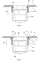
- Fig. 7 shows a measuring device for a container and a container with a thread 110 according to a sixth embodiment, in which the measuring device top 701 and the container top 111 are also arranged flush.
- the wall of the container opening is divided into a first part 711 with the thread 110 and a second part 712 without a thread, which is arranged offset to the outside from the first part.
- the housing 250 has a circumferential projection 710 on its upper part, which presses the sealing ring 145 onto the top of the first part 711 when the housing 250 is screwed into the container opening, thus achieving the sealing effect.
- the electronic unit 220 is located below the level 140 formed by the sealing ring, so that the containers with the mounted measuring devices have an external shape that allows the containers to be set up or stacked even in space-critical locations, and the measuring devices can still be flexibly removed or inserted.
Landscapes
- Physics & Mathematics (AREA)
- Engineering & Computer Science (AREA)
- Remote Sensing (AREA)
- Radar, Positioning & Navigation (AREA)
- General Physics & Mathematics (AREA)
- Electromagnetism (AREA)
- Computer Networks & Wireless Communication (AREA)
- Fluid Mechanics (AREA)
- Acoustics & Sound (AREA)
- Thermal Sciences (AREA)
- Signal Processing (AREA)
- Measurement Of Levels Of Liquids Or Fluent Solid Materials (AREA)
- Details Of Rigid Or Semi-Rigid Containers (AREA)
- Arrangements For Transmission Of Measured Signals (AREA)
Description
- Die Erfindung betrifft ein Messgerät zum Erfassen einer Prozessgröße in einem Behälter und einen Behälter mit einer Behälteröffnung und einem darin angeordneten Messgerät.
- Sensoren, die Daten oder Eigenschaften von Prozessgrößen oder Stoffen innerhalb eines Behälters erfassen, werden üblicherweise außerhalb des Behälters am Behälter montiert, oder sie werden innerhalb des Behälters montiert und der Behälter nach der Montage dicht verschlossen, so dass das Füllmedium nicht aus dem Behälter austreten kann. Daher werden sie zum Beispiel von außen mittels Schraubgewinde installiert und die Elektronikeinheit sitzt außerhalb des Behälters, während sich die Sensorik (Antenne) innerhalb des Behälters befindet. Weiterhin gibt es Messgeräte, bei denen sich z.B. lediglich eine Antenne innerhalb des Behälters befindet.
- Messgeräte bzw. Sensoren, die sich in einem dichten Behälter befinden, sind jedoch nicht ohne Weiteres flexibel montierbar oder demontierbar. Sensoren, die sich außerhalb des Behälters oder teilweise innerhalb des Behälters befinden, haben den Nachteil, dass die Behälter nicht platzsparend zusammengestellt werden können, zum Beispiel aufeinander gestapelt werden können. Des Weiteren besteht bei mobilen Behältern wie zum Beispiel sog. Intermediate Bulk Containern (IBCs, Großpackmittel) die Gefahr, dass die Sensorik beim Rangieren des Behälters mit dem Gabelstapler einen Schaden erleiden oder gar zerstört werden kann.
- Die
WO 03/085365 A1 US 6 363 784 B1 beschreibt einen Füllstanddetektor mit einem Lichtsender, einem Lichtempfänger, einer elektrischen Schaltung und einem Glasgehäuse, das den Lichtempfänger, den Lichtsender und die elektrische Schaltung im Wesentlichen einkapselt, um den Detektor vor gefährlichen Umgebungen zu schützen. - Aufgabe der Erfindung ist es daher, ein Messgerät für einen Behälter und ein Behälter mit einem Messgerät zu finden, die so gestaltet sind, dass die Behälter platzökonomisch aufgestellt werden können, und das Messgerät dennoch flexibel montierbar ist.
- Die Aufgabe wird durch die Gegenstände der unabhängigen Patentansprüche gelöst. Vorteilhafte Ausführungsformen sind Gegenstand der abhängigen Ansprüche, der folgenden Beschreibung, sowie der Figuren.
- Die Erfindung wird durch die beigefügten Ansprüche definiert. Ausführungsformen und Beispiele, die nicht in den Ansprüchen enthalten sind, werden zur Veranschaulichung und zum besseren Verständnis der beanspruchten Erfindung dargestellt.
- Gemäß einem ersten Aspekt wird ein Messgerät zum Erfassen einer Prozessgröße in einem Behälter bereitgestellt, aufweisend eine Elektronikeinheit mit einem Gehäuse und eine an dem Gehäuse anliegende Dichtanordnung. Das Messgerät ist eingerichtet, in einer Behälteröffnung angeordnet zu werden. Die Dichtanordnung ist eingerichtet, die Behälteröffnung abzudichten und die Elektronikeinheit ist unterhalb einer geometrischen Ebene der Dichtanordnung angeordnet, wenn sich das Messgerät in der Behälteröffnung befindet, d.h., wenn das Messgerät montiert ist.
- Unter Messgerät wird hierbei eine Anordnung verstanden, die eine Einheit zur physikalischen Erfassung der Prozessgröße aufweist, z.B. einen physikalischen Sensor oder eine Generator-Empfänger-Anordnung für z.B. Ultraschallwellen oder Radar, sowie eine Elektronikeinheit, die zumindest die elektrische Energieversorgung bereitstellt, und die je nach Anwendungsfall zum Beispiel die erfasste Prozessgröße elektronisch aufbereitet und als digitale Daten zur Verfügung stellt. Die elektronischen Elemente, die hierzu verwendet werden können, wie z.B. Spannungsregler, Spannungswandler, Schutzschaltungen, Analog-Digitalwandler, Filter, Verstärker, Mikroprozessoren, Speicherbausteine, Signalgeneratoren, Schwingungserzeuger, Strahler, Piezowandler, etc., sind dem Fachmann bekannt.
- Das Messgerät kann beispielsweise Substanzen oder Bestandteile eines Mediums, wie zum Beispiel einer Flüssigkeit oder eines Gases in einem Behälter bestimmen, oder eine Temperatur, einen Druck oder einen Füllstand erfassen. Das Messgerät weist, wie oben erwähnt, eine Elektronikeinheit zum Betreiben des Sensors und zum Bereitstellen der Messdaten auf, die in ein Gehäuse montiert ist. Das Gehäuse nimmt die Elektronikeinheit auf, schützt diese vor Umgebungseinflüssen und dient insbesondere zur Montage an bzw. in den Behälter. Hierzu weist das Gehäuse, gemäß einer Ausführungsform, z.B. ein Außengewinde auf, so dass es in eine Behälteröffnung mit einem entsprechenden Gewinde bis beispielsweise zu einer überstehenden Auflagefläche, z.B. einem umlaufenden Vorsprung am außerhalb des Behälters verbleibenden Ende des Gehäuses, eingeschraubt werden kann. Die Höhe des vorspringenden Teils kann z.B. so gewählt sein, dass sie eine definierte Kantenhöhe an der Oberseite des Behälters nicht überschreitet, so dass ein Stapeln der Behälter möglich ist. An der Auflagefläche zum Behälter hin umschließt eine Dichtanordnung, z.B. ein Dichtring, den Gewindeschaft am Ende des Gewindes. Vorzugsweise kann der Schaftteil, der von der Dichtanordnung umschlossen wird, gewindelos sein. Beim Einschrauben des Messgerätes wird der Dichtring gegen den Rand der Behälteröffnung gepresst, so dass eine Abdichtung des Behälters sichergestellt ist.
- Die Dichtanordnung besteht erfindungsgemäß aus einem Dichtring, der im montierten Zustand des Messgerätes entlang der z.B. kreisförmigen Behälteröffnung verläuft und den Behälter abdichtet. Die Ebene der Dichtanordnung ist in diesem Fall die Kreisebene des an der kreisförmigen Öffnung anliegenden Dichtrings. Der Begriff "unterhalb" ist hierbei in dem Bezugssystem des Messgerätes zu sehen, bei dem im montierten Zustand die Richtung "nach unten" senkrecht zur Behälteröffnung in den Behälter hineinzeigt. Wird der Sensor also am Behälterdeckel montiert, bedeutet dies, dass der Teil "unterhalb" einer geometrischen Ebene der Dichtanordnung sich innerhalb des Behälters befindet. Wird der Sensor seitlich montiert, liegt die Ebene der seitlichen Behälteröffnung senkrecht zum Behälterboden, bzw. Behälterdeckel, und "unterhalb" dieser Ebene bezeichnet den Teil des Messgerätes, der in den Behälter hineinragt. Dieser Teil beherbergt die Elektronikeinheit. Diese befindet sich somit in dem Bereich des Gehäuses, der von dem Gewinde umgeben ist und sich im eingeschraubten Zustand innerhalb des Behälters befindet, wobei "innerhalb" durch die Ebene des Dichtrings, definiert ist.
- Die Behälteröffnung kann dabei beispielsweise als Stutzen mit oder ohne Gewinde ausgebildet sein, der nach außen oder nach innen ragt. Sie kann weiterhin beispielsweise die gesamte Behälteroberseite sein, die von einem Behälterdeckel, der den Sensor aufweist, abgedeckt werden kann.
- Gemäß einer Ausführungsform kann das Gehäuse ein Innengewinde oder ein Außengewinde aufweisen. Im Falle eines Außengewindes ist das Gehäuse zylindrisch und umschließt die Elektronikeinheit. Im Falle eines Innengewindes ist das Gehäuse erweitert, so dass es den Behälterdeckel bildet und auf den Behälterrumpf geschraubt wird. Die Elektronikeinheit kann dann zum Beispiel in einem Teil des Gehäuses einstückig mit dem erweiterten Gehäuse bzw. dem Behälterdeckel verbunden sein und im montierten, d.h. eingeschraubten Zustand nach unten in Richtung Behälterboden ragen. Die Dichtanordnung mit der oben definierten Dichtebene befindet sich dann entlang des Innengewindes.
- Die Elektronikeinheit kann alternativ in einem zweiten wie oben beschriebenen Gehäuse von oben bzw. von außen in eine Behälteröffnung des ein erweitertes Gehäuse bildenden Behälterdeckels eingeschraubt werden, welcher ein Innengewinde aufweist.
- Als weitere Alternative kann die Elektronikeinheit in einem getrennten Gehäuse von unten in den Behälterdeckel eingeschraubt werden. Das getrennte Gehäuse kann dabei eine zweite Dichtanordnung am unteren Ende des Außengewindes des getrennten Gehäuses aufweisen. Für die Definition "unterhalb einer geometrischen Ebene der Dichtanordnung" ist hierbei die Dichtanordnung am Innengewinde maßgebend.
- Erfindungsgemäß weist die Elektronikeinheit einen Sensor, eine Antenne und eine Kommunikationseinheit auf. Der Sensor ist eingerichtet, ein Messsignal zu erfassen, indem er z.B. ein Radarsignal über die Antenne aussendet und das reflektierte Signal wieder über die Antenne empfängt, oder beispielsweise eine Temperatur oder einen Druck erfasst. Weiterhin kann er eine Auswerteeinheit beinhalten, die z.B. analoge Messsignale konditioniert und in digitale Daten wandelt, diese zwischenspeichert und ausgibt. Die Energieversorgung ist eingerichtet, den Sensor und eventuell die Antenne über eine geeignete Spannung mit Strom zu versorgen. Die Kommunikationseinheit ist eingerichtet, um z.B. Steuersignale zu empfangen, durch die z.B. eine Messung angestoßen wird, durch die bestimmte Daten in einem bestimmten Format abgerufen werden können oder durch die eine Synchronisation stattfinden kann. Die Kommunikationseinheit ist weiterhin zum Empfangen der digitalen Messdaten von dem Sensor, zum Einbetten und der Daten in ein Format, das einem Übertragungsprotokoll entspricht und schließlich zum Bereitstellen bzw. Übertragen der aus dem Messsignal generierten Messdaten gemäß dem Übertragungsprotokoll eingerichtet.
- Die Kommunikationseinheit weist eine Kommunikationseinheit zur drahtlosen Kommunikation, beispielsweise über einen Niedrigenergie-Funkstandard wie z.B. LoRa, Sigfox, Bluetooth LE, oder NB-IOT, sein. Die Elektronikeinheit ist hierbei eingerichtet, durch eine Batterie, z.B. eine in das Gehäuse eingebaute Primärzelle wie z.B. eine Lithium-Batterie (Lithium-Thionylchlorid), mit elektrischer Energie versorgt zu werden, so dass keine externe Verkabelung des Messgeräts notwendig ist, und der Behälter für das Messgerät an einem beliebigen Ort aufgestellt werden kann. Alternativ, hier nicht beansprucht, kann die Kommunikationseinheit eine Kommunikationseinheit zur drahtgebundenen Kommunikation sein. Hierzu ist jedoch eine externe Schnittstelle zum Anschließen von Drähten notwendig, die z.B. seitlich am Gehäuse außerhalb des Behälters angeordnet ist. Der Vorteil dieser Variante ist, dass der Strom über die externe Schnittstelle zugeführt werden kann und somit eine Überwachung der Batteriespannung und Batteriewartung entfallen kann.
- Das Gehäuse kann gemäß einer Ausführungsform zur Montage von der Behälteraußenseite aus eine Struktur zur Aufnahme eines Werkzeugs aufweisen. Eine solche Struktur ist z.B. eine Aussparung an der Oberseite des Messgeräts, die der Form des Werkzeugs, z.B. eines Fassschlüssels bzw. Spundschlüssels, entspricht, so dass das Werkzeug in die Aussparung eingreifen kann und das Ein- bzw. Ausschrauben des Messgeräts unterstützen kann.
- Gemäß einer Ausführungsform ist die zum Behälterboden gerichtete Seite des Gehäuses innerhalb des Behälters derart geformt, dass sie eine oder mehrere Neigungen gegenüber der Waagrechten zum Ableiten von Flüssigkeit oder Kondensat aufweist. Die Flüssigkeit kann beispielsweise das Medium in dem Behälter sein oder ein Kondensat, das sich am Gehäuse in dem Behälter gebildet hat. Die Neigung kann zum Beispiel durch eine konische Ausbildung am unteren Teil des gemäß einer Ausführungsform zylindrischen Gehäuses realisiert werden. Die Flüssigkeit kann z.B. entlang der Neigung zur Spitze der konischen Form abgeleitet werden und dort abtropfen.
- Das gemäß einer Ausführungsform zumindest zwischen der Dichtanordnung und der einen oder mehreren Neigungen zylindrische Gehäuse weist vorteilhafterweise in diesem Bereich einen konstanten Durchmesser auf. Beispielsweise beträgt der Durchmesser zwei Zoll. Damit kann z.B. in diesem Bereich das Gewinde, z.B. ein zwei-Zoll-Gewinde, angeordnet sein, und das gesamte Gehäuse kann bis auf den eventuell vorhandenen überstehenden Vorsprung z.B. von außen ein- und wieder ausgeschraubt werden.
- Das Messgerät schließt gemäß einer Ausführungsform auf der Außenseite bündig mit dem Behälter und/oder dem Deckel in einer Ebene ab. Dies ist möglich, wenn zum Beispiel eine Einwölbung bzw. Vertiefung des Randes der Behälteröffnung vorhanden ist, die der Höhe des überstehenden Vorsprungs des Messgeräts, also dem Teil des Gehäuses oberhalb der Ebene der Dichtanordnung, entspricht. Alternativ kann der überstehende Vorsprung des Gehäuses fehlen und die Dichtanordnung überstehend in einer Kerbe des Gehäuses eingelassen sein, so dass die Dichtanordnung seitlich gegen beispielsweise einen oberen, gewindelosen Rand der Behälteröffnung gepresst wird.
- Gemäß einer Ausführungsform weist das Messgerät ferner ein Belüftungs- und Entlüftungsventil zum Druckausgleich der Druckunterunterschiede auf, die z.B. durch Verdampfung des Mediums, Entnahme des Mediums, Befüllen des Behälters oder durch Temperaturänderungen auftreten. Hierfür werden entsprechende Kanäle zur Zu- und Ableitung der Luft oder des Gases in das Gehäuse eingebracht.
- Gemäß einer Ausführungsform ist der Sensor ein Radarsensor, ein Ultraschallsensor oder ein Sensor zur Grenzstanderfassung. Ein Sensor zur Grenzstanderfassung kann, je nach Ausführungsform, auch seitlich in den Behälter eingeschraubt werden, d.h. die Behälteröffnung befindet sich dann in der Seitenwand des Behälters.
- Gemäß einer Ausführungsform besteht das Gehäuse aus Kunststoff (z.B. Hart-Polyethylen, HDPE) und / oder Metall, wie z.B. Aluminium, Messing, oder Edelstahl.
- Gemäß einem zweiten Aspekt wird ein Behälter mit einer Behälteröffnung und einem darin angeordneten Messgerät wie oben beschrieben bereitgestellt. Der Behälter kann beispielsweise ein Fass oder ein Kanister aus Kunststoff, Weißblech, Edelstahl oder Holz sein. Ein Kanister kann zum Beispiel einen gegenüber der Oberfläche abgesenkte Schrauböffnung mit einem Außengewinde oder einem Innengewinde aufweisen. Ein Holzfass kann beispielsweise eine Öffnung aufweisen, in die ein Adapter mit einem entsprechenden Innengewinde zur Aufnahme des Messgeräts eingebracht werden kann, oder das Gehäuse kann einen sich nach unten, also in das Fass hinein, verjüngenden Gewindedurchmesser aufweisen.
- Dadurch, dass Messgerät durch seine Form vollständig oder nahezu vollständig in den Behälter eingeschraubt werden kann und nicht oder nur wenig oben herausragt, wird ermöglicht, dass mehrere Behälter z.B. aufeinandergestapelt werden können. Rechteckförmige Behälter mit seitlich montiertem Messgerät können je nach exakter Form des Behälters und Ausgestaltung des Gehäuses bzw. des Behälters ohne oder mit lediglich kleinem Abstand nebeneinander platziert werden.
- Im Folgenden werden Ausführungsbeispiele der Erfindung mit Bezug auf die beiliegenden Figuren detailliert beschrieben. Weder die Beschreibung noch die Figuren sollen als die Erfindung einschränkend ausgelegt werden. Hierbei zeigt
-
Fig. 1 ein Diagramm eines Messgeräts für einen Behälter mit einer Elektronikeinheit außerhalb des Behälters, -
Fig. 2 ein Diagramm eines Messgeräts für einen Behälter und eines Behälters gemäß einem ersten Ausführungsbeispiel mit einer Elektronikeinheit unterhalb der Dichtanordnung, -
Fig. 3 ein Diagramm eines Messgeräts für einen Behälter und eines Behälters gemäß einem zweiten Ausführungsbeispiel mit einem Be- und Entlüftungsventil, -
Fig. 4 ein Diagramm eines Messgeräts für einen Behälter und eines Behälters gemäß einem dritten Ausführungsbeispiel mit einem Grenzstandsensor nach kapazitivem Messprinzip, -
Fig. 5 ein Diagramm eines Behälterdeckels und eines Messgeräts gemäß einem vierten Ausführungsbeispiel, -
Fig. 6 ein Diagramm eines Messgeräts für einen Behälter und eine Behälters gemäß einem fünften Ausführungsbeispiel, bei dem die Messgerätoberseite und die Behälteroberseite bündig angeordnet sind, -
Fig. 7 ein Diagramm eines Messgeräts für einen Behälter und eines Behälters gemäß einem sechsten Ausführungsbeispiel, bei dem die Messgerätoberseite und die Behälteroberseite ebenfalls bündig angeordnet sind. - Die Zeichnungen sind lediglich schematisch und nicht maßstabsgetreu. Grundsätzlich sind identische oder ähnliche Teile mit den gleichen Bezugszeichen versehen.
-
Fig. 1 zeigt als Beispiel einen Füllstandsensor 100, bei dem nur die Antenne 101 in den Behälter hineinragt, während das Elektronikgehäuse 115 sich außerhalb des Behälters befindet. Die Antenne 101 sendet Signale aus, zum Beispiel ein Radarsignal, das von der Flüssigkeit 170 in dem Behälter reflektiert wird und von der Antenne 101 zur Füllstandmessung wieder empfangen wird. Das Elektronikgehäuse 115 weist ein Gewinde 105 auf, das sich unterhalb des Elektronikgehäuses befindet und das eine Durchführung in dem Gewinde aufweist, wodurch die Antenne 101, die in den Behälter hineinragt, mit dem Sensor 150 verbunden werden kann. Das Außengewinde 105 des Gehäuses 115 greift hierbei in das Innengewinde 110 des Behälterdeckels 111 sein. Der Durchmesser 120 des Elektronikgehäuses 115 kann dabei größer als der Durchmesser 130 des Gewindes sein. In dem Beispiel inFig. 1 ist das Gehäuse 115 breiter als die Öffnung für das Gewinde 105, so dass es beim Einschrauben auf die Dichtringe 145 gedrückt wird und die Anordnung dicht ist. - Die Elektronikeinheit in dem Gehäuse 115 ist in
Fig. 1 oberhalb der Ebene 140, die durch den Dichtring 145 gebildet wird. Dadurch, dass die Durchmesser 120 des Elektronikgehäuses 115 größer sind als der Durchmesser 130 des Gewindes 105, kann die Elektronikeinheit nicht in den Behälter hineinragen. Somit steht das Elektronikgehäuse 115 nach oben aus dem Behälter hervor, so dass der Behälter nicht stapelbar ist. -
Fig. 2 zeigt schematisch ein Messgerät 200 gemäß einem zweiten Ausführungsbeispiel sowie einen Behälter 111. Das Messgerät 200 beinhaltet eine Elektronikeinheit 220 mit einem Sensor 221, einer Kommunikationseinheit 222 und einer Energieversorgungseinheit 223 einschließlich einer Antenne 225. Das Gehäuse 250 des Messgeräts 200 weist weiterhin ein Gewinde 205 auf, mit dem das Messgerät 200 in eine Öffnung des Behälters eingeschraubt werden kann, der ebenfalls ein entsprechendes Gewinde 110 aufweist. Das Messgerät 200 hat einen Durchmesser, der dem Gewindedurchmesser entspricht, so dass das Messgerät 200 fast vollständig, bis auf einen überhängenden Vorsprung 280, in den Behälter 290 hineingeschraubt werden kann. Der überhängende Vorsprung 280 begrenzt das Einschrauben, so dass das Messgerät 200 nicht durch das Gewinde 110 durchgeschraubt werden kann und ermöglicht außerdem die Ausübung eines Drucks auf den Dichtring 145, so dass das Gehäuse 250 des Messgeräts 200 den Behälter 290 dicht verschließt. Antenne 225 besitzt einen maximalen Durchmesser, welcher kleiner als der des Gewindes 110 bzw. des Gewindes 205 ist. Die Wände mit dem Gewinde 110 können auch nach oben ragen, so dass sie einen nach außen gerichteten Stutzen bilden. Weiterhin kann der Flansch 280 mit dem Behälter 111 verbunden werden, so dass kein Gewinde notwendig ist. Auch in diesem Fall befindet sich die Elektronikeinheit unterhalb der durch die Dichtanordnung, beispielsweise Dichtringe, definierte Ebene. Da durch die Dichtringe zwischen Flansch und Behälter die Anordnung dicht ist, kann der Durchmesser des Gehäuses kleiner sein als der Durchmesser der Behälteröffnung bzw. des nach oben oder unten ragenden Stutzens. - Die Elektronikeinheit befindet sich somit im Wesentlichen innerhalb des Behälters im medienzugewandten Halbraum 230, dessen obere Begrenzung durch die Dichtebene 140, in der der Dichtring 145 liegt, definiert wird. Die Gehäuseform auf der Behälteraußenseite weist dabei eine Geometrie 260 auf, welche das Einschrauben mit einem entsprechenden Werkzeug, beispielsweise einem Spundlochschlüssel, Fassöffnungsschlüssel, Fassschlüssel, lBC-Deckelschlüssel oder einem Sechskantschlüssel, erleichtert. Des Weiteren besitzt die Gehäusespitze eine beispielsweise konische Geometrie 250, welche das Abtropfen von Kondensat und Medium 270 erleichtert.
-
Fig. 3 zeigt ein Messgerät 300 in einer weiteren Ausführungsform, welcher zusätzlich zu den inFigur 2 gezeigten Merkmalen ein Be- und Entlüftungsventil 301 aufweist, welches über die Gaskanäle 310 einen Druckausgleich zwischen der Behälterinnenseite und der Umgebung ermöglicht, um Befüll- bzw. Entleervorgänge zu erleichtern. -
Fig. 4 zeigt ein Messgerät 400 in einer weiteren Ausführungsform, wobei es sich bei dem Sensor 401 um einen Grenzstandsensor 401 handelt, welcher beispielsweise nach dem kapazitiven Messprinzip funktioniert. Das heißt, gegenüber der Anordnung inFig. 2 fehlt die Antenne 225, und die Kommunikationseinheit 402 und die Energieversorgungseinheit 403 liegen über dem Grenzstandsensor 401. Auch in diesem Ausführungsbeispiel ist die komplette Elektronikeinheit bestehend aus Kommunikationseinheit 402, Energieversorgungseinheit 403 und Grenzstandsensor 401 komplett unterhalb der Dichtebene 140 angeordnet. Lediglich der obere Vorsprung 280 ragt aus dem Behälter heraus. Je nach eingesetztem Messprinzip kann die Geometrie des dem Medium zugewandten Gehäuseteiles entsprechend der physikalischen Anforderung des Messprinzips ausgestaltet sein. -
Fig. 5 zeigt einen Behälterdeckel 530 und ein Messgerät 500, das einstückig in den Behälterdeckel 530 integriert ist, in einer weiteren Ausführungsform. Der Behälterdeckel 530 weist ein Innengewinde 505 auf, so dass er auf den Behälter geschraubt werden kann. Der Behälterdeckel kann beispielsweise in der Größe DN 150 mit NW 150 - Innengewinde S 165x7 bzw. in der Größe DN 225 mit NW 225 - Innengewinde S245x6 ausgeführt sein, sowie einen oder mehrere optionale Gewindeanschlüsse 510 mit jeweils einer optionalen Behälteröffnung 520 zum Einschrauben z.B. eines Messgeräts oder zum Einführen eines Saugstutzens aufweisen. Gemäß den Ausführungsbeispielen kann der Behälterdeckel 530 auch entweder nur das einstückig integrierte Messgerät 500 aufweisen, das heißt ohne weitere Behälteröffnung 520 und Gewinde 510. Des Weiteren kann der Behälterdeckel 530 nur die Öffnung 520 mit Gewinde 510 ohne Messgerät 500 aufweisen, in das ein oben erläutertes Messgerät eingeschraubt werden kann. Die Dichtebene des Messgerätes liegt auch in diesen Ausführungsbeispielen oberhalb der Elektronikeinheit 220. Des Weiteren kann der Deckel auch ein Be- und Entlüftungsventil aufweisen. -
Fig. 6 zeigt ein Messgerät für einen Behälter und einen Behälter gemäß einem fünften Ausführungsbeispiel, bei dem die Messgeräteoberseite 601 und die Behälteroberseite 111 im montierten Zustand bündig, d.h. planar sind. Der Dichtring 145 wird beim bzw. nach dem Eindrehen seitlich an die Behälteröffnung gepresst wird. Vorzugsweise weist die Wand der Behälteröffnung am oberen Teil kein Gewinde auf, so dass der Dichtring beim Einschrauben an diesem Teil der Wand nach unten gleiten kann. -
Fig. 7 zeigt ein Messgerät für einen Behälter und einen Behälter mit einem Gewinde 110 gemäß einem sechsten Ausführungsbeispiel, bei dem die Messgerätoberseite 701 und die Behälteroberseite 111 ebenfalls bündig angeordnet sind. In diesem Beispiel ist die Wand der Behälteröffnung in einen ersten Teil 711 mit dem Gewinde 110 und einen zweiten Teil 712 ohne Gewinde, der zu dem ersten Teil nach außen versetzt angeordnet ist, unterteilt. Das Gehäuse 250 weist an seinem oberen Teil einen umlaufenden Vorsprung 710 auf, der beim Eindrehen des Gehäuses 250 in die Behälteröffnung den Dichtring 145 auf die Oberseite des ersten Teils 711 presst und somit die Dichtwirkung erreicht wird. - Auch in den Ausführungsbeispielen nach
Fig. 6 und Fig. 7 befindet sich die Elektronikeinheit 220 jeweils unterhalb der aus dem Dichtring gebildeten Ebene 140, so dass die Behälter mit den montierten Messgeräten eine äußere Form aufweisen, die es erlaubt, die Behälter auch an platzkritischen Orten aufzustellen bzw. zu stapeln, und wobei die Messgeräte dennoch flexibel entnehmbar oder einsetzbar sind.
Claims (11)
- Messgerät (200) zum Erfassen einer Prozessgröße in einem Behälter, aufweisend eine Elektronikeinheit (220) mit einem Gehäuse (250) und eine an dem Gehäuse (250) anliegende Dichtanordnung (145), wobeidas Messgerät (200) eingerichtet ist, in einer Behälteröffnung angeordnet zu werden; wobei,wenn sich das Messgerät (200) in der Behälteröffnung befindet, die Dichtanordnung (145) eingerichtet ist, die Behälteröffnung abzudichten;wobei die Elektronikeinheit (220) aufweist:einen Sensor (221) zum Erfassen eines Messsignals;eine Energieversorgung (223);eine Antenne (225), die mit dem Sensor (221) verbunden ist, zum Senden und Empfangen des Messsignals; undeine Kommunikationseinheit (222), zum Empfangen von Steuersignalen, und zum Bereitstellen und Übertragen von Messdaten aus dem Messsignal gemäß einem Übertragungsprotokoll;dadurch gekennzeichnet, dass die Elektronikeinheit unterhalb einer geometrischen Ebene der Dichtanordnung und gleichzeitig innerhalb des Behälters angeordnet ist, und die Dichtanordnung als Dichtring ausgestaltet ist,und dass die Kommunikationseinheit (222) eine Kommunikationseinheit zur drahtlosen Kommunikation ist, und die Elektronikeinheit (220) eingerichtet ist, durch eine Batterie mit elektrischer Energie versorgt zu werden.
- Messgerät (200) nach Anspruch 1, wobei das Gehäuse (250) ein Gewinde (205) zum Einschrauben des Messgeräts (200) in die Behälteröffnung aufweist.
- Messgerät (200) nach Anspruch 2, wobei das Gewinde (250) ein Innengewinde oder ein Außengewinde ist.
- Messgerät (200) nach einem der vorhergehenden Ansprüche, wobei das Gehäuse (250) zur Montage von der Behälteraußenseite aus eine Struktur (260) zur Aufnahme eines Werkzeugs aufweist.
- Messgerät (200) nach einem der vorhergehenden Ansprüche, wobei die zum Behälterboden gerichtete Seite des Gehäuses (250) innerhalb des Behälters derart geformt ist, dass sie eine oder mehrere Neigungen gegenüber der Waagrechten zum Ableiten von Flüssigkeit oder Kondensat aufweist.
- Messgerät (200) nach einem der vorhergehenden Ansprüche, wobei das Messgerät (200) auf der Außenseite bündig mit dem Behälter und/oder einem Deckel des Behälters in einer Ebene abschließt.
- Messgerät (200) nach einem der vorhergehenden Ansprüche, wobei das Gehäuse (250) zumindest zwischen der Dichtanordnung (145) und der einen oder mehreren Neigungen eine zylindrische Form mit konstantem Durchmesser aufweist.
- Messgerät (200) nach einem der vorhergehenden Ansprüche, wobei das Messgerät (200) ferner ein Be- und Entlüftungsventil (301) aufweist.
- Messgerät (200) nach einem der vorhergehenden Ansprüche, wobei der Sensor (221) ein Radarsensor, ein Ultraschallsensor oder ein Sensor zur Grenzstanderfassung ist.
- Messgerät (200) nach einem der vorhergehenden Ansprüche, wobei das Gehäuse (250) aus Kunststoff und / oder Metall besteht.
- Behälter mit einer Behälteröffnung und einem darin angeordneten Messgerät (200) nach einem der Ansprüche 1 bis 10.
Priority Applications (4)
| Application Number | Priority Date | Filing Date | Title |
|---|---|---|---|
| RS20250347A RS66712B1 (sr) | 2019-07-30 | 2019-07-30 | Merni uređaj za određivanje procesne promenljive u rezervoaru |
| PL19752658.5T PL4004498T3 (pl) | 2019-07-30 | 2019-07-30 | Urządzenie pomiarowe do ustalania wielkości procesowej w zbiorniku |
| HUE19752658A HUE071132T2 (hu) | 2019-07-30 | 2019-07-30 | Mérõeszköz tartályban lévõ folyamatváltozó rögzítésére |
| HRP20250441TT HRP20250441T1 (hr) | 2019-07-30 | 2019-07-30 | Mjerni uređaj za određivanje procesne varijable u spremniku |
Applications Claiming Priority (1)
| Application Number | Priority Date | Filing Date | Title |
|---|---|---|---|
| PCT/EP2019/070471 WO2021018384A1 (de) | 2019-07-30 | 2019-07-30 | Messgerät zum erfassen einer prozessgrösse in einem behälter |
Publications (3)
| Publication Number | Publication Date |
|---|---|
| EP4004498A1 EP4004498A1 (de) | 2022-06-01 |
| EP4004498B1 true EP4004498B1 (de) | 2025-02-12 |
| EP4004498C0 EP4004498C0 (de) | 2025-02-12 |
Family
ID=67614549
Family Applications (1)
| Application Number | Title | Priority Date | Filing Date |
|---|---|---|---|
| EP19752658.5A Active EP4004498B1 (de) | 2019-07-30 | 2019-07-30 | Messgerät zum erfassen einer prozessgrösse in einem behälter |
Country Status (9)
| Country | Link |
|---|---|
| US (1) | US20220291331A1 (de) |
| EP (1) | EP4004498B1 (de) |
| CN (1) | CN113811746A (de) |
| ES (1) | ES3021877T3 (de) |
| HR (1) | HRP20250441T1 (de) |
| HU (1) | HUE071132T2 (de) |
| PL (1) | PL4004498T3 (de) |
| RS (1) | RS66712B1 (de) |
| WO (1) | WO2021018384A1 (de) |
Families Citing this family (2)
| Publication number | Priority date | Publication date | Assignee | Title |
|---|---|---|---|---|
| DE102018117164A1 (de) * | 2018-07-16 | 2020-01-16 | Endress+Hauser SE+Co. KG | Füllstandsmessgerät |
| AT17018U1 (de) * | 2019-10-29 | 2021-02-15 | Tdk Electronics Ag |
Citations (3)
| Publication number | Priority date | Publication date | Assignee | Title |
|---|---|---|---|---|
| WO1992021943A1 (de) * | 1991-06-07 | 1992-12-10 | Endress U. Hauser Gmbh U. Co. | Vorrichtung zur elektrisch isolierten befestigung einer metallischen sondenelektrode in der öffnung eines gehäuses |
| WO2000029819A1 (en) * | 1998-11-12 | 2000-05-25 | Rosemount Inc. | Ptfe window seal with emi shielding |
| US6363784B1 (en) * | 1999-02-09 | 2002-04-02 | Liquip Sales Pty Limited | Fluid detector |
Family Cites Families (15)
| Publication number | Priority date | Publication date | Assignee | Title |
|---|---|---|---|---|
| GB694125A (en) * | 1950-10-24 | 1953-07-15 | Oldham & Son Ltd | Improvements in or relating to liquid level indicators |
| DE19752808C2 (de) * | 1997-11-28 | 2001-12-06 | Grieshaber Vega Kg | Antenneneinrichtung für ein Füllstandmeß-Radargerät |
| AU762027B2 (en) * | 1999-02-09 | 2003-06-19 | Liquip International Pty Limited | Fluid detector |
| DE10019129A1 (de) * | 2000-04-18 | 2001-10-25 | Endress Hauser Gmbh Co | Vorrichtung zur Bestimmung des Füllstandes eines Füllguts in einem Behälter |
| US7626508B2 (en) * | 2002-03-05 | 2009-12-01 | Aeromesh Corporation | Monitoring system and method |
| EP3159663B1 (de) * | 2002-04-10 | 2020-12-16 | VEGA Grieshaber KG | Radarfüllstandmessgerät mit elektronik und antenne in gekapseltem gehäuse |
| US7513152B2 (en) * | 2005-03-04 | 2009-04-07 | Vega Grieshaber Kg | Container arrangement with a level sensor, and a level sensor for a container arrangement |
| ITRE20070048A1 (it) * | 2007-04-04 | 2008-10-05 | Ufi Innovation Ct Srl | '' rilevatore di livello e metodo per rilevare il livello di un fluido in un recipiente'' |
| DE102007057211A1 (de) * | 2007-11-26 | 2009-05-28 | Martin Meyer | Verschluss mit Füllstandssensor |
| DE102008054942B4 (de) * | 2008-12-18 | 2021-02-11 | Endress+Hauser SE+Co. KG | Vorrichtung zur Bestimmung und/oder Überwachung einer Prozessgröße |
| US8154313B1 (en) * | 2009-09-24 | 2012-04-10 | Christopher Ralph Cantolino | Water detection assembly for primary drain lines |
| US8701483B2 (en) * | 2010-12-16 | 2014-04-22 | Vega Grieshaber Kg | Device for emulsion measuring by means of a standpipe |
| DE102012016120B4 (de) * | 2012-08-15 | 2017-12-07 | Krohne Messtechnik Gmbh | Mikrowellenfenster und nach dem Radar-Prinzip arbeitendes Füllstandmesssystem |
| US10066979B2 (en) * | 2014-12-03 | 2018-09-04 | Rochester Gauges, Inc. | Sealed head construction for liquid level transducers |
| HRP20221114T1 (hr) * | 2015-03-27 | 2022-11-25 | Vega Grieshaber Kg | Radarski uređaj za mjerenje razine napunjenosti s integriranim senzorom granične razine |
-
2019
- 2019-07-30 CN CN201980096239.4A patent/CN113811746A/zh active Pending
- 2019-07-30 HR HRP20250441TT patent/HRP20250441T1/hr unknown
- 2019-07-30 US US17/626,270 patent/US20220291331A1/en active Pending
- 2019-07-30 PL PL19752658.5T patent/PL4004498T3/pl unknown
- 2019-07-30 HU HUE19752658A patent/HUE071132T2/hu unknown
- 2019-07-30 WO PCT/EP2019/070471 patent/WO2021018384A1/de not_active Ceased
- 2019-07-30 RS RS20250347A patent/RS66712B1/sr unknown
- 2019-07-30 EP EP19752658.5A patent/EP4004498B1/de active Active
- 2019-07-30 ES ES19752658T patent/ES3021877T3/es active Active
Patent Citations (3)
| Publication number | Priority date | Publication date | Assignee | Title |
|---|---|---|---|---|
| WO1992021943A1 (de) * | 1991-06-07 | 1992-12-10 | Endress U. Hauser Gmbh U. Co. | Vorrichtung zur elektrisch isolierten befestigung einer metallischen sondenelektrode in der öffnung eines gehäuses |
| WO2000029819A1 (en) * | 1998-11-12 | 2000-05-25 | Rosemount Inc. | Ptfe window seal with emi shielding |
| US6363784B1 (en) * | 1999-02-09 | 2002-04-02 | Liquip Sales Pty Limited | Fluid detector |
Also Published As
| Publication number | Publication date |
|---|---|
| ES3021877T3 (en) | 2025-05-27 |
| CN113811746A (zh) | 2021-12-17 |
| HUE071132T2 (hu) | 2025-08-28 |
| RS66712B1 (sr) | 2025-05-30 |
| EP4004498C0 (de) | 2025-02-12 |
| HRP20250441T1 (hr) | 2025-06-06 |
| EP4004498A1 (de) | 2022-06-01 |
| PL4004498T3 (pl) | 2025-07-07 |
| US20220291331A1 (en) | 2022-09-15 |
| WO2021018384A1 (de) | 2021-02-04 |
Similar Documents
| Publication | Publication Date | Title |
|---|---|---|
| DE69816267T2 (de) | Modulare sonde | |
| EP1537388A1 (de) | Ausrichtvorrichtung für ein messgerät | |
| EP4004498B1 (de) | Messgerät zum erfassen einer prozessgrösse in einem behälter | |
| DE102010030924A1 (de) | Elektronik-Gehäuse für ein elektronisches Gerät bzw. damit gebildetes Gerät | |
| WO1992021943A1 (de) | Vorrichtung zur elektrisch isolierten befestigung einer metallischen sondenelektrode in der öffnung eines gehäuses | |
| DE102018102366A1 (de) | Füllstandsmessgerät | |
| EP2808660B1 (de) | Gehäuse für eine Wägevorrichtung | |
| DE102013109280B3 (de) | Behälterdeckel zum Verschließen eines Transport- und/oder Lagerbehälters | |
| WO2004022456A2 (de) | Behälter- oder flanschdeckel | |
| EP3408636B1 (de) | Lecksuche an einem flexiblen prüfling in einer folienkammer | |
| DE202020107286U1 (de) | Sensorvorrichtung und Erweiterungsmodul | |
| EP3802195B1 (de) | Ladestation zum aufladen eines energiespeichers eines elektrofahrzeugs | |
| DE102018206292B3 (de) | Einschraubbares Druckausgleichselement für ein Gehäuse einer elektronischen Vorrichtung, ein Druckausgleichssystem mit einem solchen Druckausgleichselement und ein Messgerät mit einem solchen Druckausgleichselement oder Druckausgleichssystem | |
| DE102017130328A1 (de) | Lastaufnahmebauteil für Ketten | |
| EP3748312B1 (de) | Messgerät mit flansch und behälter mit diesem messgerät | |
| EP3479092B1 (de) | Prüfanordnung für ein explosionsgeschütztes gehäuses, explosionsgeschütztes gehäuse mit einer prüfanordnung sowie verfahren zur herstellung und prüfung eines explosionsgeschützten gehäuses | |
| EP3201593B1 (de) | Prüfscheibensystem | |
| DE102019220041A1 (de) | Schnellwechselbarer Füllstandsensor | |
| DE102010012375A1 (de) | Transportkappe | |
| DE3643920A1 (de) | Bleiakkumulator in blockausfuehrung | |
| DE102018125840A1 (de) | Tool Center Point | |
| DE202014105651U1 (de) | Elektronisches Gerät | |
| DE102022121389A1 (de) | Feldgerät der Automatisierungstechnik | |
| EP4138212A1 (de) | Radom-freie antennen-einheit | |
| WO2022008076A1 (de) | Messanordnung zur anbringung an einem deckel eines behältnisses |
Legal Events
| Date | Code | Title | Description |
|---|---|---|---|
| STAA | Information on the status of an ep patent application or granted ep patent |
Free format text: STATUS: UNKNOWN |
|
| STAA | Information on the status of an ep patent application or granted ep patent |
Free format text: STATUS: THE INTERNATIONAL PUBLICATION HAS BEEN MADE |
|
| PUAI | Public reference made under article 153(3) epc to a published international application that has entered the european phase |
Free format text: ORIGINAL CODE: 0009012 |
|
| STAA | Information on the status of an ep patent application or granted ep patent |
Free format text: STATUS: REQUEST FOR EXAMINATION WAS MADE |
|
| 17P | Request for examination filed |
Effective date: 20220228 |
|
| AK | Designated contracting states |
Kind code of ref document: A1 Designated state(s): AL AT BE BG CH CY CZ DE DK EE ES FI FR GB GR HR HU IE IS IT LI LT LU LV MC MK MT NL NO PL PT RO RS SE SI SK SM TR |
|
| DAV | Request for validation of the european patent (deleted) | ||
| DAX | Request for extension of the european patent (deleted) | ||
| STAA | Information on the status of an ep patent application or granted ep patent |
Free format text: STATUS: EXAMINATION IS IN PROGRESS |
|
| 17Q | First examination report despatched |
Effective date: 20221122 |
|
| GRAP | Despatch of communication of intention to grant a patent |
Free format text: ORIGINAL CODE: EPIDOSNIGR1 |
|
| STAA | Information on the status of an ep patent application or granted ep patent |
Free format text: STATUS: GRANT OF PATENT IS INTENDED |
|
| RIC1 | Information provided on ipc code assigned before grant |
Ipc: H01Q 19/08 20060101ALN20240821BHEP Ipc: H01Q 1/44 20060101ALN20240821BHEP Ipc: G01S 15/88 20060101ALI20240821BHEP Ipc: H01Q 1/22 20060101ALI20240821BHEP Ipc: G01S 13/88 20060101ALI20240821BHEP Ipc: G01F 23/284 20060101AFI20240821BHEP |
|
| INTG | Intention to grant announced |
Effective date: 20240904 |
|
| GRAS | Grant fee paid |
Free format text: ORIGINAL CODE: EPIDOSNIGR3 |
|
| GRAA | (expected) grant |
Free format text: ORIGINAL CODE: 0009210 |
|
| STAA | Information on the status of an ep patent application or granted ep patent |
Free format text: STATUS: THE PATENT HAS BEEN GRANTED |
|
| AK | Designated contracting states |
Kind code of ref document: B1 Designated state(s): AL AT BE BG CH CY CZ DE DK EE ES FI FR GB GR HR HU IE IS IT LI LT LU LV MC MK MT NL NO PL PT RO RS SE SI SK SM TR |
|
| RAP3 | Party data changed (applicant data changed or rights of an application transferred) |
Owner name: VEGA GRIESHABER KG |
|
| REG | Reference to a national code |
Ref country code: GB Ref legal event code: FG4D Free format text: NOT ENGLISH |
|
| REG | Reference to a national code |
Ref country code: CH Ref legal event code: EP |
|
| REG | Reference to a national code |
Ref country code: DE Ref legal event code: R096 Ref document number: 502019012917 Country of ref document: DE |
|
| REG | Reference to a national code |
Ref country code: IE Ref legal event code: FG4D Free format text: LANGUAGE OF EP DOCUMENT: GERMAN |
|
| U01 | Request for unitary effect filed |
Effective date: 20250310 |
|
| U07 | Unitary effect registered |
Designated state(s): AT BE BG DE DK EE FI FR IT LT LU LV MT NL PT RO SE SI Effective date: 20250317 |
|
| REG | Reference to a national code |
Ref country code: ES Ref legal event code: FG2A Ref document number: 3021877 Country of ref document: ES Kind code of ref document: T3 Effective date: 20250527 |
|
| REG | Reference to a national code |
Ref country code: HR Ref legal event code: T1PR Ref document number: P20250441 Country of ref document: HR |
|
| PG25 | Lapsed in a contracting state [announced via postgrant information from national office to epo] |
Ref country code: IS Free format text: LAPSE BECAUSE OF FAILURE TO SUBMIT A TRANSLATION OF THE DESCRIPTION OR TO PAY THE FEE WITHIN THE PRESCRIBED TIME-LIMIT Effective date: 20250612 Ref country code: NO Free format text: LAPSE BECAUSE OF FAILURE TO SUBMIT A TRANSLATION OF THE DESCRIPTION OR TO PAY THE FEE WITHIN THE PRESCRIBED TIME-LIMIT Effective date: 20250512 |
|
| PG25 | Lapsed in a contracting state [announced via postgrant information from national office to epo] |
Ref country code: GR Free format text: LAPSE BECAUSE OF FAILURE TO SUBMIT A TRANSLATION OF THE DESCRIPTION OR TO PAY THE FEE WITHIN THE PRESCRIBED TIME-LIMIT Effective date: 20250513 |
|
| REG | Reference to a national code |
Ref country code: HR Ref legal event code: ODRP Ref document number: P20250441 Country of ref document: HR Payment date: 20250718 Year of fee payment: 7 |
|
| REG | Reference to a national code |
Ref country code: HU Ref legal event code: AG4A Ref document number: E071132 Country of ref document: HU |
|
| U20 | Renewal fee for the european patent with unitary effect paid |
Year of fee payment: 7 Effective date: 20250729 |
|
| PGFP | Annual fee paid to national office [announced via postgrant information from national office to epo] |
Ref country code: HU Payment date: 20250728 Year of fee payment: 7 |
|
| PG25 | Lapsed in a contracting state [announced via postgrant information from national office to epo] |
Ref country code: SM Free format text: LAPSE BECAUSE OF FAILURE TO SUBMIT A TRANSLATION OF THE DESCRIPTION OR TO PAY THE FEE WITHIN THE PRESCRIBED TIME-LIMIT Effective date: 20250212 |
|
| PGFP | Annual fee paid to national office [announced via postgrant information from national office to epo] |
Ref country code: ES Payment date: 20250819 Year of fee payment: 7 |
|
| PGFP | Annual fee paid to national office [announced via postgrant information from national office to epo] |
Ref country code: PL Payment date: 20250721 Year of fee payment: 7 |
|
| PGFP | Annual fee paid to national office [announced via postgrant information from national office to epo] |
Ref country code: GB Payment date: 20250724 Year of fee payment: 7 |
|
| PGFP | Annual fee paid to national office [announced via postgrant information from national office to epo] |
Ref country code: HR Payment date: 20250718 Year of fee payment: 7 |
|
| PGFP | Annual fee paid to national office [announced via postgrant information from national office to epo] |
Ref country code: CH Payment date: 20250801 Year of fee payment: 7 |
|
| PGFP | Annual fee paid to national office [announced via postgrant information from national office to epo] |
Ref country code: CZ Payment date: 20250717 Year of fee payment: 7 Ref country code: RS Payment date: 20250729 Year of fee payment: 7 |
|
| PG25 | Lapsed in a contracting state [announced via postgrant information from national office to epo] |
Ref country code: SK Free format text: LAPSE BECAUSE OF FAILURE TO SUBMIT A TRANSLATION OF THE DESCRIPTION OR TO PAY THE FEE WITHIN THE PRESCRIBED TIME-LIMIT Effective date: 20250212 |
|
| PGFP | Annual fee paid to national office [announced via postgrant information from national office to epo] |
Ref country code: MK Payment date: 20250721 Year of fee payment: 7 |