EP4004349B1 - Pressure control for closed joule circuit processes - Google Patents
Pressure control for closed joule circuit processes Download PDFInfo
- Publication number
- EP4004349B1 EP4004349B1 EP20746900.8A EP20746900A EP4004349B1 EP 4004349 B1 EP4004349 B1 EP 4004349B1 EP 20746900 A EP20746900 A EP 20746900A EP 4004349 B1 EP4004349 B1 EP 4004349B1
- Authority
- EP
- European Patent Office
- Prior art keywords
- working fluid
- heat exchanger
- gas
- working
- gas line
- Prior art date
- Legal status (The legal status is an assumption and is not a legal conclusion. Google has not performed a legal analysis and makes no representation as to the accuracy of the status listed.)
- Active
Links
- 238000000034 method Methods 0.000 title claims description 38
- 239000012530 fluid Substances 0.000 claims description 50
- 238000001816 cooling Methods 0.000 claims description 9
- 238000010438 heat treatment Methods 0.000 claims description 7
- 238000011144 upstream manufacturing Methods 0.000 claims description 2
- 239000007789 gas Substances 0.000 description 91
- 230000008901 benefit Effects 0.000 description 6
- 239000003949 liquefied natural gas Substances 0.000 description 5
- IJGRMHOSHXDMSA-UHFFFAOYSA-N Atomic nitrogen Chemical compound N#N IJGRMHOSHXDMSA-UHFFFAOYSA-N 0.000 description 4
- 230000000694 effects Effects 0.000 description 3
- 230000006835 compression Effects 0.000 description 2
- 238000007906 compression Methods 0.000 description 2
- 238000012423 maintenance Methods 0.000 description 2
- 239000000463 material Substances 0.000 description 2
- 229910052757 nitrogen Inorganic materials 0.000 description 2
- 238000009833 condensation Methods 0.000 description 1
- 230000005494 condensation Effects 0.000 description 1
- 125000004122 cyclic group Chemical group 0.000 description 1
- 238000011161 development Methods 0.000 description 1
- 230000018109 developmental process Effects 0.000 description 1
- 230000007613 environmental effect Effects 0.000 description 1
- 238000000605 extraction Methods 0.000 description 1
- 239000001307 helium Substances 0.000 description 1
- 229910052734 helium Inorganic materials 0.000 description 1
- SWQJXJOGLNCZEY-UHFFFAOYSA-N helium atom Chemical compound [He] SWQJXJOGLNCZEY-UHFFFAOYSA-N 0.000 description 1
- 238000009434 installation Methods 0.000 description 1
- 230000010354 integration Effects 0.000 description 1
- 238000005457 optimization Methods 0.000 description 1
- 230000035484 reaction time Effects 0.000 description 1
- 239000011343 solid material Substances 0.000 description 1
- 239000002918 waste heat Substances 0.000 description 1
- XLYOFNOQVPJJNP-UHFFFAOYSA-N water Substances O XLYOFNOQVPJJNP-UHFFFAOYSA-N 0.000 description 1
Images

Classifications
-
- F—MECHANICAL ENGINEERING; LIGHTING; HEATING; WEAPONS; BLASTING
- F01—MACHINES OR ENGINES IN GENERAL; ENGINE PLANTS IN GENERAL; STEAM ENGINES
- F01K—STEAM ENGINE PLANTS; STEAM ACCUMULATORS; ENGINE PLANTS NOT OTHERWISE PROVIDED FOR; ENGINES USING SPECIAL WORKING FLUIDS OR CYCLES
- F01K25/00—Plants or engines characterised by use of special working fluids, not otherwise provided for; Plants operating in closed cycles and not otherwise provided for
-
- F—MECHANICAL ENGINEERING; LIGHTING; HEATING; WEAPONS; BLASTING
- F01—MACHINES OR ENGINES IN GENERAL; ENGINE PLANTS IN GENERAL; STEAM ENGINES
- F01K—STEAM ENGINE PLANTS; STEAM ACCUMULATORS; ENGINE PLANTS NOT OTHERWISE PROVIDED FOR; ENGINES USING SPECIAL WORKING FLUIDS OR CYCLES
- F01K13/00—General layout or general methods of operation of complete plants
- F01K13/02—Controlling, e.g. stopping or starting
-
- F—MECHANICAL ENGINEERING; LIGHTING; HEATING; WEAPONS; BLASTING
- F02—COMBUSTION ENGINES; HOT-GAS OR COMBUSTION-PRODUCT ENGINE PLANTS
- F02C—GAS-TURBINE PLANTS; AIR INTAKES FOR JET-PROPULSION PLANTS; CONTROLLING FUEL SUPPLY IN AIR-BREATHING JET-PROPULSION PLANTS
- F02C1/00—Gas-turbine plants characterised by the use of hot gases or unheated pressurised gases, as the working fluid
- F02C1/04—Gas-turbine plants characterised by the use of hot gases or unheated pressurised gases, as the working fluid the working fluid being heated indirectly
- F02C1/10—Closed cycles
-
- F—MECHANICAL ENGINEERING; LIGHTING; HEATING; WEAPONS; BLASTING
- F02—COMBUSTION ENGINES; HOT-GAS OR COMBUSTION-PRODUCT ENGINE PLANTS
- F02C—GAS-TURBINE PLANTS; AIR INTAKES FOR JET-PROPULSION PLANTS; CONTROLLING FUEL SUPPLY IN AIR-BREATHING JET-PROPULSION PLANTS
- F02C6/00—Plural gas-turbine plants; Combinations of gas-turbine plants with other apparatus; Adaptations of gas-turbine plants for special use
- F02C6/14—Gas-turbine plants having means for storing energy, e.g. for meeting peak loads
- F02C6/16—Gas-turbine plants having means for storing energy, e.g. for meeting peak loads for storing compressed air
-
- F—MECHANICAL ENGINEERING; LIGHTING; HEATING; WEAPONS; BLASTING
- F05—INDEXING SCHEMES RELATING TO ENGINES OR PUMPS IN VARIOUS SUBCLASSES OF CLASSES F01-F04
- F05D—INDEXING SCHEME FOR ASPECTS RELATING TO NON-POSITIVE-DISPLACEMENT MACHINES OR ENGINES, GAS-TURBINES OR JET-PROPULSION PLANTS
- F05D2270/00—Control
- F05D2270/30—Control parameters, e.g. input parameters
- F05D2270/301—Pressure
-
- F—MECHANICAL ENGINEERING; LIGHTING; HEATING; WEAPONS; BLASTING
- F05—INDEXING SCHEMES RELATING TO ENGINES OR PUMPS IN VARIOUS SUBCLASSES OF CLASSES F01-F04
- F05D—INDEXING SCHEME FOR ASPECTS RELATING TO NON-POSITIVE-DISPLACEMENT MACHINES OR ENGINES, GAS-TURBINES OR JET-PROPULSION PLANTS
- F05D2270/00—Control
- F05D2270/30—Control parameters, e.g. input parameters
- F05D2270/306—Mass flow
- F05D2270/3061—Mass flow of the working fluid
-
- Y—GENERAL TAGGING OF NEW TECHNOLOGICAL DEVELOPMENTS; GENERAL TAGGING OF CROSS-SECTIONAL TECHNOLOGIES SPANNING OVER SEVERAL SECTIONS OF THE IPC; TECHNICAL SUBJECTS COVERED BY FORMER USPC CROSS-REFERENCE ART COLLECTIONS [XRACs] AND DIGESTS
- Y02—TECHNOLOGIES OR APPLICATIONS FOR MITIGATION OR ADAPTATION AGAINST CLIMATE CHANGE
- Y02E—REDUCTION OF GREENHOUSE GAS [GHG] EMISSIONS, RELATED TO ENERGY GENERATION, TRANSMISSION OR DISTRIBUTION
- Y02E60/00—Enabling technologies; Technologies with a potential or indirect contribution to GHG emissions mitigation
- Y02E60/16—Mechanical energy storage, e.g. flywheels or pressurised fluids
Definitions
- the invention relates to a device comprising a closed gas system with a working circuit, and a method for controlling the pressure in a closed gas system.
- closed gas systems Due to the given system volume, closed gas systems are subject to temperature and/or mass flow-induced pressure fluctuations. In the case of closed Joule cycle processes (Brayton cycles), these pressure fluctuations and the set upper/lower system pressure have specific effects on the performance of the process.
- the JP H08 68341 A discloses an apparatus for controlling the power of a closed Joule cycle gas turbine. Furthermore, the U.S. 5,131,231A a method of operating a closed cycle engine and an engine suitable for use with the method.
- the object of the invention is to provide a device that enables improved part-load efficiency for a closed Joule cycle.
- a further object of the invention is to specify a corresponding method for pressure regulation in such a closed gas system.
- the lower process pressure should be operated as a function of the cyclic process output, as can be seen as the standard on the upper process pressure side (sliding pressure operation in steam and gas turbines to avoid throttling losses at part load).
- the circulating medium is too valuable (e.g. when using pure nitrogen or even helium) or may be too polluting to accept more than minimal losses to the environment.
- the invention solves the object directed at a device by providing that in such a device, comprising a closed gas system with a working circuit in which a compressor for a working fluid, a first heat exchanger for heating the working fluid, an expander (gas expansion turbine) and a second heat exchanger for cooling the working fluid are arranged, a first gas pressure vessel and a first gas line are provided, the gas line between the compressor and the first heat exchanger branching off from the working circuit and opening into the first gas pressure vessel, and also a second gas line is provided is, which branches off from the first gas pressure vessel and opens into the working circuit between the expander and the second heat exchanger.
- the invention thus provides a gas pressure vessel (or if necessary, several if more economical) on the high pressure side (ie behind the compressor of the closed Joule cycle process is connected to the work process with its own gas line for filling the container.
- the container is always filled when it is necessary from the point of view of the process (e.g. the system pressure is reduced during shutdown in order to reduce standstill losses). For this purpose, a partial flow is diverted from the Joule cycle.
- another gas line is integrated into the working circuit after the expander.
- a third gas line branches off from the gas pressure container or from the second gas line and opens into the working circuit between the compressor and the first heat exchanger.
- a third heat exchanger is arranged in the first gas line.
- the gas is cooled after compression before it is advantageously released via a corresponding first valve in the first gas line, which is thus arranged downstream of the third heat exchanger in the direction of flow of the working fluid. is released into the gas pressure tank.
- this relaxation results in further cooling due to the Joule-Thomson effect.
- a first valve is expediently arranged in the first gas line in the direction of flow of the working fluid before the third heat exchanger.
- a fourth heat exchanger is arranged in the second gas line and a fifth heat exchanger is arranged in the third gas line.
- the second and the third gas line are feed-back lines from the first gas pressure vessel into the working circuit.
- the fourth and fifth heat exchangers are typically heated using waste heat (e.g. from the intermediate cooling system of the power plant) and heat the gas before it enters the working circuit, i.e. the working circuit.
- waste heat e.g. from the intermediate cooling system of the power plant
- the gas heating reduces the cooling effect on the gas already in the working circuit and the pressure increase in the working circuit desired via the gas make-up occurs faster and with less mass flow.
- At least one thermal accumulator is connected to the third, fourth or fifth heat exchanger via switchable connecting lines.
- a thermal storage device which absorbs the heat of the working gas before it enters the pressure vessel and then later heats it up again before the working gas is fed back into the circuit. This can be achieved by using a container filled with a solid material that stores heat well and is operated as a regenerator. By appropriate switching of connecting lines, this container is flowed through by the heat-emitting or absorbing gas in the opposite direction.
- At least one second gas pressure tank is connected in parallel with the first gas pressure tank and the gas pressure tanks can be operated at different pressure levels are.
- the use of several gas pressure vessels, which store the working gas at different pressure levels, makes it possible to fill a comparatively small pressure vessel "HP" with high pressure when the expander outlet pressure and the resulting high compressor outlet pressure in the working circuit are high. By removing this working gas from the working circuit, the pressure in the same then drops. The working gas removed in the further course is then stored in the pressure vessel "LP" at a lower pressure level. This makes it possible to optimize the overall container size and, in particular, to lower the working circuit pressure to the lowest possible overpressure when shutting down. This lowest possible working circuit overpressure is desirable in order to keep downtime losses due to leakage through the shaft seals of the compressor or expander as low as possible.
- the compressor comprises at least two compressor stages and a fifth gas line branches off the working circuit between two compressor stages and opens into at least one of the gas pressure vessels. In this way, the compressor power consumption or the size/design of the gas pressure vessel(s) is/are optimized.
- the object directed to a method is solved by a method for pressure regulation in a closed gas system, wherein a working fluid is compressed, heated, expanded and cooled repeatedly one after the other in a working circuit.
- a partial flow of the working fluid is removed from the working circuit and stored, or a stored quantity of working fluid is reintroduced into the working circuit, with the stored quantity of working fluid being incorporated into the working circuit between expansion and cooling of the working fluid.
- the working fluid is extracted from the closed gas system after it has been at least partially compressed and before it is heated by heat exchange.
- the working fluid is first cooled via a heat exchange when the Joule-Thomson coefficient is positive and then expanded into a gas pressure vessel by means of a valve, and when the Joule-Thomson coefficient is negative, first expanded via the valve and then, if necessary, via a heat exchange cooled and then stored.
- a thermal store is charged when the working fluid cools and discharged when the working fluid is heated.
- the inventive concept of a gas pressure maintenance and gas pressure regulation for closed circuits can be used advantageously in a wide variety of closed Joule cycle-based power plant processes, eg also in the context of an LNG regasification power plant (LNG: short for "liquefied natural gas”).
- LNG LNG regasification power plant
- the cycle gas is at a comparatively low/moderate temperature (i.e.
- the pressure maintenance in the system is ensured in the first step. Furthermore, a cost-effective solution can be provided through the connection on the high-pressure side of the compressor already present in the Joule cycle (ie this compressor does not have to be provided additionally).
- the tank configuration also benefits from the high pressure.
- high pressure means a correspondingly reduced volume and, associated with this, a reduced container size.
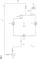
- the figure 1 shows schematically and by way of example a device 1 comprising a closed gas system 2 with a working circuit 3, in which a compressor 4 for a working fluid, a first heat exchanger 5 for heating the working fluid, an expander 6 (gas expansion turbine) and a second Heat exchanger 7 are arranged to cool the working fluid.
- a first gas line 9 branches off between the compressor 4 and the first heat exchanger 5 from the working circuit 3 and opens into the first gas pressure vessel 8. Furthermore, a second gas line 10 branches off from the first gas pressure vessel 8 and opens out between the expander 6 and the second heat exchanger 7 in the work cycle 3.
- make-up with make-up point 21, make-up line 22 and make-up pump 23 is used to compensate for the normal gas loss in the system.
- a third gas line 11 branches off from the first gas pressure vessel 8 or from the second gas line 10 and opens into the working circuit 3 between the compressor 4 and the first heat exchanger 5.
- FIG. 2 three additional heat exchangers.
- a third heat exchanger 12 arranged in the first gas line 9 cools the gaseous working fluid, whereas a fourth heat exchanger 14 in the second gas line 10 and a fifth heat exchanger 15 in the third gas line 11 serve to heat the working fluid.
- first valve 13 in the first gas line 9 which is arranged after the third heat exchanger 12 in the direction of flow of the working fluid. This is the relative arrangement of the two components when the working fluid cools as it expands. If the working fluid heats up during relaxation, the arrangement of the valve 13 and the third heat exchanger 12 is reversed. This is in the figure 2 marked with a dashed double arrow.
- FIG. 1 In addition to the out figure 1 already known first gas pressure vessel 8, the embodiment of figure 2 a second gas pressure tank 19 which is connected in parallel to the first gas pressure tank 8 . A corresponding second valve 20 is in the figure 2 shown. Typically, the gas pressure tanks 8, 19 can be operated at different pressure levels.
- a useful addition to the concept presented is the installation of a thermal storage device 16, which is connected to the third 12, fourth 14 or fifth heat exchanger 15 via switchable connecting lines A, B, C.
Landscapes
- Engineering & Computer Science (AREA)
- Chemical & Material Sciences (AREA)
- Combustion & Propulsion (AREA)
- Mechanical Engineering (AREA)
- General Engineering & Computer Science (AREA)
- Filling Or Discharging Of Gas Storage Vessels (AREA)
- Engine Equipment That Uses Special Cycles (AREA)
Description
Die Erfindung betrifft eine Vorrichtung umfassend ein geschlossenes Gassystem mit einem Arbeitskreislauf, sowie ein Verfahren zur Druckregelung in einem geschlossenen Gassystem.The invention relates to a device comprising a closed gas system with a working circuit, and a method for controlling the pressure in a closed gas system.
Geschlossene Gassysteme unterliegen wegen des vorgegebenen Systemvolumens temperatur- und/oder massenstrominduzierten Druckschwankungen, letztere treten durch gezielte Gaszufuhr bzw. -abfuhr sowie durch nicht vermeidbare Gasverluste durch Systemleckagen auf. Bei geschlossenen Joule-Kreisprozessen (engl.: Brayton cycles) haben diese Druckschwankungen bzw. der jeweils eingestellte obere/untere Systemdruck konkrete Auswirkungen auf die Leistungsfähigkeit des Prozesses.Due to the given system volume, closed gas systems are subject to temperature and/or mass flow-induced pressure fluctuations. In the case of closed Joule cycle processes (Brayton cycles), these pressure fluctuations and the set upper/lower system pressure have specific effects on the performance of the process.
Kreisprozesse sind bekannt, beispielsweise aus der
Die
Aufgabe der Erfindung ist es, eine Vorrichtung bereitzustellen, die für einen geschlossenen Joule-Kreisprozess einen verbesserten Teillastwirkungsgrad ermöglicht. Eine weitere Aufgabe der Erfindung ist es, ein entsprechendes Verfahren zur Druckregelung in einem solchen geschlossenen Gassystem anzugeben.The object of the invention is to provide a device that enables improved part-load efficiency for a closed Joule cycle. A further object of the invention is to specify a corresponding method for pressure regulation in such a closed gas system.
Geschlossene Joule-Kreisprozesse stellen besondere Anforderungen an die Systemauslegung, da ein definierter unterer Prozessdruck, z.B. durch die Umgebung oder durch einen Kondensationsprozess, fehlt. Dieser untere Prozessdruck muss deshalb über eine entsprechende Systemdruckregelmöglichkeit eingestellt werden. Dabei gilt es die Druckänderungen durch Änderungen der Prozessarbeitstemperaturen auszugleichen.Closed Joule cycle processes make special demands on the system design, since a defined lower Process pressure, eg from the environment or from a condensation process, is missing. This lower process pressure must therefore be set using a corresponding system pressure control option. It is important to compensate for the changes in pressure caused by changes in the process working temperatures.
Der untere Prozessdruck sollte in Abhängigkeit der Kreisprozessleistung gleitend gefahren werden, so wie dies auf der oberen Prozessdruckseite als Standard angesehen werden kann (Gleitdruckfahrweise bei Dampf- und Gasturbinen zur Vermeidung von Drosselverlusten in Teillast). Darüber hinaus bestehen in der Regel wirtschaftlich oder aus Umweltschutzsicht begründete Anforderungen, die Gasabgabe aus dem System in die Umgebung soweit möglich ganz zu vermeiden oder zumindest möglichst gering zu halten, da das Kreislaufmedium zu wertvoll (z.B. bei Verwendung von reinem Stickstoff oder gar Helium) oder ggf. zu umweltschädlich ist, als dass man mehr als nur minimale Verluste in die Umgebung akzeptieren kann.The lower process pressure should be operated as a function of the cyclic process output, as can be seen as the standard on the upper process pressure side (sliding pressure operation in steam and gas turbines to avoid throttling losses at part load). In addition, there are usually economic or environmental requirements to avoid the gas release from the system into the environment as far as possible or at least to keep it as low as possible, since the circulating medium is too valuable (e.g. when using pure nitrogen or even helium) or may be too polluting to accept more than minimal losses to the environment.
Ausgehend von diesen Überlegungen löst die Erfindung die auf eine Vorrichtung gerichtete Aufgabe, indem sie vorsieht, dass bei einer derartigen Vorrichtung, umfassend ein geschlossenes Gassystem mit einem Arbeitskreislauf, in dem ein Verdichter für ein Arbeitsfluid, ein erster Wärmeübertrager zur Erwärmung des Arbeitsfluids, ein Expander (Gasexpansionsturbine) und ein zweiter Wärmeübertrager zur Abkühlung des Arbeitsfluids angeordnet sind, ein erster Gasdruckbehälter und eine erste Gasleitung vorgesehen sind, wobei die Gasleitung zwischen dem Verdichter und dem ersten Wärmeübertrager vom Arbeitskreislauf abzweigt und in den ersten Gasdruckbehälter mündet, sowie ferner eine zweite Gasleitung vorgesehen ist, die vom ersten Gasdruckbehälter abzweigt und zwischen dem Expander und dem zweiten Wärmeübertrager in den Arbeitskreislauf mündet.Based on these considerations, the invention solves the object directed at a device by providing that in such a device, comprising a closed gas system with a working circuit in which a compressor for a working fluid, a first heat exchanger for heating the working fluid, an expander (gas expansion turbine) and a second heat exchanger for cooling the working fluid are arranged, a first gas pressure vessel and a first gas line are provided, the gas line between the compressor and the first heat exchanger branching off from the working circuit and opening into the first gas pressure vessel, and also a second gas line is provided is, which branches off from the first gas pressure vessel and opens into the working circuit between the expander and the second heat exchanger.
Die Erfindung sieht also einen Gasdruckbehälter vor (oder falls wirtschaftlicher ggf. auch mehrere), der auf der Hochdruckseite (d.h. hinter dem Verdichter des geschlossenen Joule-Kreisprozesses am Arbeitsprozess mit einer eigenen Gasleitung zum Befüllen des Behälters angeschlossen wird. Der Behälter wird immer dann befüllt, wenn es aus Sicht des Prozesses erforderlich ist (z.B. wird während des Abfahrens der Systemdruck verringert, um Stillstandsverluste zu senken). Dazu wird ein Teilstrom aus dem Joule-Kreisprozess ausgeleitet. Um die eingespeicherte Gasmenge im Bedarfsfall in das System abzugeben, wird eine weitere Gasleitung nach dem Expander in den Arbeitskreislauf eingebunden.The invention thus provides a gas pressure vessel (or if necessary, several if more economical) on the high pressure side (ie behind the compressor of the closed Joule cycle process is connected to the work process with its own gas line for filling the container. The container is always filled when it is necessary from the point of view of the process (e.g. the system pressure is reduced during shutdown in order to reduce standstill losses). For this purpose, a partial flow is diverted from the Joule cycle. In order to release the stored gas volume into the system if necessary, another gas line is integrated into the working circuit after the expander.
In einem vorteilhaften Ausführungsbeispiel der Erfindung zweigt eine dritte Gasleitung vom Gasdruckbehälter oder von der zweiten Gasleitung ab und mündet zwischen Verdichter und erstem Wärmeübertrager in den Arbeitskreislauf. Diese weitere Einbindung, jetzt aber auf der Hochdruckseite und vor der Erwärmung des Kreislaufmediums ermöglicht die Nutzung der eingespeicherten Druckenergie während des Anfahrvorganges.In an advantageous exemplary embodiment of the invention, a third gas line branches off from the gas pressure container or from the second gas line and opens into the working circuit between the compressor and the first heat exchanger. This further integration, but now on the high-pressure side and before the heating of the circulating medium, enables the stored pressure energy to be used during the start-up process.
Es ist vorteilhaft, wenn ein dritter Wärmeübertrager in der ersten Gasleitung angeordnet ist. Mit diesem beispielsweise über Umgebungskälte rückgekühlten Wärmeübertrager (die übertragene Wärme könnte auch eingespeichert werden) wird das Gas nach der Verdichtung gekühlt, bevor es vorteilhafterweise über ein entsprechendes erstes Ventil in der ersten Gasleitung, welches somit in Strömungsrichtung des Arbeitsfluids nach dem dritten Wärmeübertrager angeordnet ist, in den Gasdruckbehälter entspannt wird. Aus dieser Entspannung resultiert je nach eingesetztem Gas eine weitere Abkühlung wegen des Joule-Thomson-Effektes.It is advantageous if a third heat exchanger is arranged in the first gas line. With this heat exchanger, which is re-cooled using ambient cold (the heat transferred could also be stored), the gas is cooled after compression before it is advantageously released via a corresponding first valve in the first gas line, which is thus arranged downstream of the third heat exchanger in the direction of flow of the working fluid. is released into the gas pressure tank. Depending on the gas used, this relaxation results in further cooling due to the Joule-Thomson effect.
Falls wegen des Joule-Thomson-Koeffizientens (der die Stärke und Richtung der Temperaturänderung beschreibt) des jeweiligen Gases eine Erwärmung auf Grund der Entspannung erfolgt, ist zweckmäßigerweise ein erstes Ventil in der ersten Gasleitung in Strömungsrichtung des Arbeitsfluids vor dem dritten Wärmeübertrager angeordnet. Diese Maßnahmen dienen zur Erhöhung der Gasdichte, um somit die eingespeicherte Gasmenge bei gegebenem Behältervolumen zu erhöhen.If because of the Joule-Thomson coefficient (which describes the magnitude and direction of the temperature change) of the respective gas, heating occurs due to expansion, a first valve is expediently arranged in the first gas line in the direction of flow of the working fluid before the third heat exchanger. These measures serve to increase the gas density in order to increase the amount of gas stored for a given container volume.
In einem vorteilhaften Ausführungsbeispiel der Erfindung ist ein vierter Wärmeübertrager in der zweiten Gasleitung und ein fünfter Wärmeübertrager in der dritten Gasleitung angeordnet. Die zweite und die dritte Gasleitung sind Rückspeiseleitungen vom ersten Gasdruckbehälter in den Arbeitskreislauf. Der vierte und der fünfte Wärmeübertrager werden typischerweise mittels Abwärme (z.B. aus dem Zwischenkühlsystem des Kraftwerkes) beheizt und wärmen das Gas vor Eintritt in den Arbeitskreislauf, d.h. den Arbeitskreislauf auf. Die Gaserwärmung reduziert den Kühleffekt auf das bereits im Arbeitskreislauf befindliche Gas und die über die Gasnachspeisung gewünschte Druckerhöhung im Arbeitskreislauf erfolgt schneller und mit weniger Massenstrom.In an advantageous exemplary embodiment of the invention, a fourth heat exchanger is arranged in the second gas line and a fifth heat exchanger is arranged in the third gas line. The second and the third gas line are feed-back lines from the first gas pressure vessel into the working circuit. The fourth and fifth heat exchangers are typically heated using waste heat (e.g. from the intermediate cooling system of the power plant) and heat the gas before it enters the working circuit, i.e. the working circuit. The gas heating reduces the cooling effect on the gas already in the working circuit and the pressure increase in the working circuit desired via the gas make-up occurs faster and with less mass flow.
In einem weiteren vorteilhaften Ausführungsbeispiel der Erfindung ist mindestens ein thermischer Speicher über umschaltbare Verbindungsleitungen mit dem dritten, vierten oder fünften Wärmeübertrager verbunden. Gerade bei Kraftwerksanlagen, die oft die Leistungsabgabe stark ändern müssen, kann es vorteilhaft sein, einen solchen thermischen Speicher vorzusehen, welcher die Wärme des Arbeitsgases vor Eintritt in den Druckbehälter aufnimmt und dann später vor Rückspeisung des Arbeitsgases in den Kreislauf dieses wieder aufwärmt. Dies kann durch einen als Regenerator betriebenen, mit einem gut wärmespeichernden Feststoff befüllten Behälter erreicht werden. Durch entsprechende Umschaltung von Verbindungsleitungen, wird dieser Behälter von dem wärmeabgebenden bzw. aufnehmenden Gas jeweils in umgekehrter Richtung durchströmt.In a further advantageous exemplary embodiment of the invention, at least one thermal accumulator is connected to the third, fourth or fifth heat exchanger via switchable connecting lines. Especially in power plants, which often have to change the power output significantly, it can be advantageous to provide such a thermal storage device, which absorbs the heat of the working gas before it enters the pressure vessel and then later heats it up again before the working gas is fed back into the circuit. This can be achieved by using a container filled with a solid material that stores heat well and is operated as a regenerator. By appropriate switching of connecting lines, this container is flowed through by the heat-emitting or absorbing gas in the opposite direction.
Da Leckageverluste nicht ausbleiben ist es sinnvoll, wenn Arbeitsfluid nachspeisbar ist. Zweckmäßigerweise erfolgt dies auf der Niederdruckseite des Arbeitskreislaufes und vor der Kühlung, also zwischen Expander und zweitem Wärmeübertrager.Since leakage losses are inevitable, it makes sense if the working fluid can be refilled. This is expediently done on the low-pressure side of the working circuit and before the cooling, ie between the expander and the second heat exchanger.
Es ist vorteilhaft, wenn dem ersten Gasdruckbehälter mindestens ein zweiter Gasdruckbehälter parallelgeschaltet ist und die Gasdruckbehälter auf unterschiedlichen Druckniveaus betreibbar sind. Die Nutzung mehrerer Gasdruckbehälter, welche das Arbeitsgas auf jeweils unterschiedlichen Druckniveaus speichern, ermöglicht es, bei hohem Expanderaustrittsdruck und demzufolge hohem Verdichteraustrittsdruck im Arbeitskreislauf einen vergleichsweise kleinen Druckbehälter "HP" mit hohem Druck zu befüllen. Durch die Entnahme dieses Arbeitsgases aus dem Arbeitskreislauf sinkt daraufhin der Druck im selbigen. Das im weiteren Verlauf entnommene Arbeitsgas wird dann im Druckbehälter "LP" auf einem niedrigeren Druckniveau eingespeichert. Dies ermöglicht es, die Gesamtbehältergröße zu optimieren und insbesondere beim Abfahren den Arbeitskreislaufdruck auf einen möglichst geringen Überdruck abzusenken. Dieser möglichst geringe Arbeitskreislaufüberdruck ist erstrebenswert, um Stillstandsverluste durch Leckage über die Wellendichtungen von Verdichter bzw. Expander gering zu halten.It is advantageous if at least one second gas pressure tank is connected in parallel with the first gas pressure tank and the gas pressure tanks can be operated at different pressure levels are. The use of several gas pressure vessels, which store the working gas at different pressure levels, makes it possible to fill a comparatively small pressure vessel "HP" with high pressure when the expander outlet pressure and the resulting high compressor outlet pressure in the working circuit are high. By removing this working gas from the working circuit, the pressure in the same then drops. The working gas removed in the further course is then stored in the pressure vessel "LP" at a lower pressure level. This makes it possible to optimize the overall container size and, in particular, to lower the working circuit pressure to the lowest possible overpressure when shutting down. This lowest possible working circuit overpressure is desirable in order to keep downtime losses due to leakage through the shaft seals of the compressor or expander as low as possible.
Um eine möglichst hohe Druckerhöhung bzw. Verdichtung des Arbeitsfluids zu erreichen, können mehrere Verdichterstufen hintereinandergeschaltet werden. In diesem Zusammenhang ist es vorteilhaft, wenn der Verdichter mindestens zwei Verdichterstufen umfasst und eine fünfte Gasleitung zwischen zwei Verdichterstufen vom Arbeitskreislauf abzweigt und in zumindest einen der Gasdruckbehälter mündet. Auf diese Weise wird die Verdichterleistungsaufnahme bzw. Größe/Ausführung des/der Gasdruckbehälter(s) optimiert.In order to achieve the highest possible pressure increase or compression of the working fluid, several compressor stages can be connected in series. In this context, it is advantageous if the compressor comprises at least two compressor stages and a fifth gas line branches off the working circuit between two compressor stages and opens into at least one of the gas pressure vessels. In this way, the compressor power consumption or the size/design of the gas pressure vessel(s) is/are optimized.
Die auf ein Verfahren gerichtete Aufgabe wird gelöst durch ein Verfahren zur Druckregelung in einem geschlossenen Gassystem, wobei ein Arbeitsfluid wiederholt nacheinander in einem Arbeitskreislauf verdichtet, erwärmt, entspannt und abgekühlt wird. Gemäß der Erfindung wird zur Regelung eines Drucks im Gassystem ein Teilstrom des Arbeitsfluids aus dem Arbeitskreislauf entnommen und gespeichert, oder eine gespeicherte Arbeitsfluidmenge wieder in den Arbeitskreislauf eingebunden, wobei die gespeicherte Arbeitsfluidmenge zwischen Entspannung und Abkühlung des Arbeitsfluids im Arbeitskreislauf in diesen eingebunden wird.The object directed to a method is solved by a method for pressure regulation in a closed gas system, wherein a working fluid is compressed, heated, expanded and cooled repeatedly one after the other in a working circuit. According to the invention, in order to control a pressure in the gas system, a partial flow of the working fluid is removed from the working circuit and stored, or a stored quantity of working fluid is reintroduced into the working circuit, with the stored quantity of working fluid being incorporated into the working circuit between expansion and cooling of the working fluid.
Die Vorteile dieses Verfahrens entsprechen den oben erwähnten Vorteilen gemäß der erfindungsgemäßen Vorrichtung.The advantages of this method correspond to the advantages mentioned above according to the device according to the invention.
Vorteilhafterweise wird das Arbeitsfluid aus dem geschlossenen Gassystem entnommen, nachdem es zumindest teilweise verdichtet wurde und bevor es durch Wärmetausch erwärmt wird.Advantageously, the working fluid is extracted from the closed gas system after it has been at least partially compressed and before it is heated by heat exchange.
Weiterhin vorteilhaft ist es, wenn das entnommene Arbeitsfluid gekühlt wird, bevor es eingespeichert wird.It is also advantageous if the working fluid removed is cooled before it is stored.
Dabei ist es zweckmäßig, wenn das Arbeitsfluid bei positivem Joule-Thomson-Koeffizienten zuerst über einen Wärmetausch gekühlt und dann mittels eines Ventils in einen Gasdruckbehälter entspannt wird und bei negativem Joule-Thomson-Koeffizienten zuerst über das Ventil entspannt und dann ggf. über einen Wärmetausch gekühlt und danach eingespeichert wird.It is expedient if the working fluid is first cooled via a heat exchange when the Joule-Thomson coefficient is positive and then expanded into a gas pressure vessel by means of a valve, and when the Joule-Thomson coefficient is negative, first expanded via the valve and then, if necessary, via a heat exchange cooled and then stored.
Es ist ferner zweckmäßig, wenn das Arbeitsfluid, bevor es in den Arbeitskreislauf wieder eingebunden wird, erwärmt wird.It is also expedient if the working fluid is heated before it is reintegrated into the working cycle.
Vorteilhafterweise wird ein thermischer Speicher beim Abkühlen des Arbeitsfluids geladen und beim Erwärmen des Arbeitsfluids entladen.Advantageously, a thermal store is charged when the working fluid cools and discharged when the working fluid is heated.
Schließlich ist es vorteilhaft, wenn bei unterschiedlichen Drücken aus dem Arbeitskreislauf entnommenes Arbeitsfluid verschiedenen Gasdruckbehältern zugeführt wird.Finally, it is advantageous if working fluid taken from the working circuit at different pressures is supplied to different gas pressure containers.
Das erfindungsgemäße Konzept einer Gasdruckhalte- und Gasdruckregelung für geschlossene Kreisläufe kann vorteilhaft in verschiedensten geschlossenen Joule-Kreislauf-basierten Kraftwerksprozessen eingesetzt werden, z.B. auch im Rahmen eines LNG-Wiedervergasungskraftwerkes (LNG: kurz für "liquified natural gas"). Damit verbunden ist u.a., dass der Verlust an wertvollem Kreislaufgas (im Falle des LNG-Wiedervergasungskraftwerkes: wasser- und CO2-freier Stickstoff) minimiert wird und gleichzeitig Drosselverluste im Arbeitskreislauf in Teillast, etc. vermieden werden. Das Kreislaufgas wird dabei bei vergleichsweise niedriger / moderater Temperatur (d.h. viel Masse bei gegebenem Volumen - entweder weil das Kreislaufgas bereits mit vergleichsweise niedriger Temperatur wie beim LNG-Wiedervergasungskraftwerk aus dem Verdichter austritt und/oder weil es zusätzlich vor Eintritt in den Druckbehälter gekühlt wurde) in einem begrenzten Behältervolumen eingespeichert. Aufgrund der moderaten Temperaturen kann außerdem vergleichsweise günstiges Material für das System eingesetzt werden.The inventive concept of a gas pressure maintenance and gas pressure regulation for closed circuits can be used advantageously in a wide variety of closed Joule cycle-based power plant processes, eg also in the context of an LNG regasification power plant (LNG: short for "liquefied natural gas"). This means, among other things, that the loss of valuable cycle gas (in the case of the LNG regasification power plant: nitrogen free of water and CO 2 ) is minimized and at the same time throttling losses in the working cycle in partial load, etc. can be avoided. The cycle gas is at a comparatively low/moderate temperature (i.e. a lot of mass for a given volume - either because the cycle gas exits the compressor at a comparatively low temperature, as in the case of the LNG regasification power plant, and/or because it was additionally cooled before entering the pressure vessel). stored in a limited container volume. Due to the moderate temperatures, comparatively cheap material can also be used for the system.
Mit dem vorgeschlagenen Konzept wird im ersten Schritt die Druckhaltung im System sichergestellt. Des Weiteren kann durch die Anbindung auf der Hochdruckseite des bereits im Joule-Kreisprozess vorhandenen Verdichters (d.h. dieser Verdichter muss nicht zusätzlich bereitgestellt werden) eine kostengünstige Lösung bereitgestellt werden. Im Hinblick auf die Kosten profitiert auch die Behälterkonfiguration vom hohen Druck. Hoher Druck bedeutet bei einer definierten Ausgleichsmenge ein entsprechend reduziertes Volumen und damit verbunden, eine reduzierte Behältergröße. Durch Wahl eines Druckes entsprechend einer Zwischenentnahme aus dem Verdichter kann darüber hinaus immer der aus wirtschaftlicher Sicht günstigste Druck gewählt werden (für den Fall, dass die mit dem Druck zunehmende Behälterwandstärke bzw. das zu wählende Material die Kostensenkung durch Behältervolumenreduktion überkompensiert.) Außerdem ermöglicht der hohe Druck im Behälter über die Anbindung am Arbeitskreislauf eine schnelle Reaktionszeit der Druckregelung. Damit gelingt es, die Druckregelgeschwindigkeit für einen Gleitdruckbetrieb auf dem unteren Prozessdruck mit der Druckänderungsgeschwindigkeit auf dem oberen Prozessdruck zu synchronisieren. Der Systemgleitdruckbetrieb (unterer + oberer Prozessdruck) lässt einen maximalen Wirkungsgrad des Kreisprozesses erwarten, da die bestimmenden Arbeitsmaschinen (Verdichter, Expander) ohne größere Regeleingriffe auskommen (d.h. voll geöffnete Regelventile bzw. Leitstufen) und die bestimmenden mittleren Prozesstemperaturen im ähnlichen Verhältnis mitgleiten. Falls eine Einspeiseleitung stromauf des Expanders vorgesehen ist, besteht ein weiterer Vorteil der Lösung darin, dass die eingespeicherte Druckenergie beim Anfahren des Prozesses mitgenutzt werden kann. Die entsprechende Volumenänderungsarbeit im Expander ermöglicht das direkte (Expander treibt den Verdichter an der gemeinsamen Welle an) oder indirekte (der Generator am Expander stellt die Energie für den Motor am Verdichter bereit) "Anstoßen" des Verdichters im Arbeitskreislauf.With the proposed concept, the pressure maintenance in the system is ensured in the first step. Furthermore, a cost-effective solution can be provided through the connection on the high-pressure side of the compressor already present in the Joule cycle (ie this compressor does not have to be provided additionally). In terms of costs, the tank configuration also benefits from the high pressure. With a defined compensation quantity, high pressure means a correspondingly reduced volume and, associated with this, a reduced container size. By selecting a pressure corresponding to an intermediate extraction from the compressor, the most economical pressure can always be selected (in the event that the container wall thickness, which increases with the pressure, or the material to be selected, overcompensates for the cost reduction through a reduction in container volume). high pressure in the container via the connection to the working circuit, a fast reaction time of the pressure control. This makes it possible to synchronize the pressure control speed for variable pressure operation at the lower process pressure with the pressure change speed at the upper process pressure. The system sliding pressure operation (lower + upper process pressure) allows us to expect maximum efficiency of the cycle process, since the determining working machines (compressor, expander) can do without major control interventions (ie fully open control valves or guide stages) and the determining mean process temperatures slide along in a similar ratio. If one Feed line is provided upstream of the expander, another advantage of the solution is that the stored pressure energy can be used when starting the process. The corresponding volume change work in the expander enables the direct (expander drives the compressor on the common shaft) or indirect (the generator on the expander provides the energy for the motor on the compressor) "kicking" of the compressor in the working cycle.
Ungesteuerte massenstrominduzierte Druckänderungen (z. B. wegen Gasleckagen an den Arbeitsmaschinen) werden durch eine Zusatzgaszuführung hinter dem Expander ausgeglichen. Dies hat den Vorteil, dass die Nachspeisung bei vergleichsweise niedrigem Druck erfolgt und somit der entsprechende Aufwand für einen entsprechenden separaten Verdichter, etc. begrenzt ist. Neben den bisher als Anwendungsfall angesprochenen geschlossenen Joule-Kraftwerksprozessen eignet sich das Konzept auch sehr gut, um Wärmepumpen (welche ein Gas als Arbeitsmittel ohne Phasenwechsel verwenden und neben dem üblichen Verdichter auch einen Expander aufweisen) in der Teillast zu regeln. Auch hier ist der Vorteil, dass Drosselorgane und damit zusammenhängende Verluste entfallen.Uncontrolled pressure changes induced by the mass flow (e.g. due to gas leaks on the working machines) are compensated for by an additional gas supply downstream of the expander. This has the advantage that the make-up takes place at a comparatively low pressure and the corresponding effort for a corresponding separate compressor, etc. is therefore limited. In addition to the closed Joule power plant processes previously mentioned as an application, the concept is also very well suited to controlling heat pumps (which use a gas as the working fluid without phase change and have an expander in addition to the usual compressor) in partial load. Here, too, the advantage is that there are no throttling devices and the associated losses.
Die Erfindung wird beispielhaft anhand der Zeichnungen näher erläutert. Es zeigen schematisch und nicht maßstäblich:
- Figur 1
- das Grundkonzept für ein geschlossenes Gassystem mit Druckregelung gemäß der Erfindung und
Figur 2- ein geschlossenes Gassystem mit verschiedenen Weiterbildungen des Grundkonzepts der
Figur 1 .
- figure 1
- the basic concept for a closed gas system with pressure control according to the invention and
- figure 2
- a closed gas system with various developments of the basic concept of
figure 1 .
Die
Im Ausführungsbeispiel der
Da Leckagen nicht ausbleiben, ist Arbeitsfluid zwischen Expander 6 und zweitem Wärmeübertrager 7 nachspeisbar. Die Nachspeisung mit Nachspeisestelle 21, Nachspeiseleitung 22 und Nachspeisepumpe 23 wird genutzt, um den normalen Gasverlust im System auszugleichen.Since leaks are inevitable, working fluid can be fed in between the expander 6 and the
Die
Ferner zeigt das Ausführungsbeispiel der
Bezüglich der Einspeicherung des Arbeitsfluids in den ersten Gasdruckbehälter 8 zeigt die
Zusätzlich zu dem aus
Das Vorhandensein zweier Verdichterstufen 17 am Verdichter 4 ist für das Speichern des Arbeitsfluids bei unterschiedlichen Drücken zwar nicht zwingend (man kann sich vorstellen, dass nach einem ersten Ausspeichern in den ersten Gasdruckbehälter 8 der Systemdruck gefallen ist und somit ein zweites Ausspeichern in den zweiten Gasdruckbehälter 19 bei niedrigerem Druck erfolgt), erleichtert allerdings Optimierungen. Dies wird ergänzt durch eine fünfte Gasleitung 18, die zwischen zwei Verdichterstufen 17 vom Kreislauf 3 abzweigt und in zumindest einen der Gasdruckbehälter 8, 19 mündet.The presence of two
Eine sinnvolle Ergänzung des vorgestellten Konzepts ist die Installation eines thermischen Speichers 16, der über umschaltbare Verbindungsleitungen A, B, C mit dem dritten 12, vierten 14 oder fünften Wärmeübertrager 15 verbunden ist.A useful addition to the concept presented is the installation of a
Claims (17)
- Apparatus (1), comprising a closed gas system (2) with a working circuit (3), in which a compressor (4) for a working fluid, a first heat exchanger (5) for heating the working fluid, an expander (6) and a second heat exchanger (7) for cooling the working fluid are arranged, comprising a first pressurized gas tank (8) and a first gas line (9), which branches off from the working circuit (3) between the compressor (4) and the first heat exchanger (5) and opens into the first pressurized gas tank (8), and also a second gas line (10), which branches off from the first pressurized gas tank (8), characterized in that the second gas line (10) opens into the working circuit (3) between the expander (6) and the second heat exchanger (7).
- Apparatus (1) according to Claim 1, wherein a third gas line (11) branches off from the pressurized gas tank (8) or from the second gas line (10) and opens into the working circuit (3) between the compressor (4) and the first heat exchanger (5).
- Apparatus (1) according to either of the preceding claims, wherein a third heat exchanger (12) is arranged in the first gas line (9).
- Apparatus (1) according to Claim 3, wherein a first valve (13) is arranged in the first gas line (9) downstream of the third heat exchanger (12) in the direction of flow of the working fluid.
- Apparatus (1) according to Claim 3, wherein a first valve (13) is arranged in the first gas line (9) upstream of the third heat exchanger (12) in the direction of flow of the working fluid.
- Apparatus (1) according to Claim 2, wherein a fourth heat exchanger (14) is arranged in the second gas line (10) and a fifth heat exchanger (15) is arranged in the third gas line (11) .
- Apparatus (1) according to Claims 3 and 6, wherein at least one thermal store (16) is connected by way of switchable connecting lines (A, B, C) to the third heat exchanger (12), fourth heat exchanger (14) or fifth heat exchanger (15).
- Apparatus (1) according to one of the preceding claims, wherein working fluid can be replenished between the expander (6) and the second heat exchanger (7).
- Apparatus (1) according to one of the preceding claims, wherein at least one second pressurized gas tank (19) is connected in parallel with the first pressurized gas tank (8) and the pressurized gas tanks (8, 19) can be operated at different pressure levels.
- Apparatus (1) according to Claim 9, wherein the compressor (4) comprises at least two compressor stages (17) and a fifth gas line (18) branches off from the circuit (3) between two compressor stages (17) and opens into at least one of the pressurized gas tanks (8, 19).
- Method for pressure control in a closed gas system (2), wherein a working fluid is compressed, heated, expanded and cooled repeatedly one after the other in a working circuit (3), wherein, for controlling a pressure in the gas system (2), a partial stream of the working fluid is removed from the working circuit (3) and stored, or a stored amount of working fluid is incorporated again into the working circuit (3), characterized in that the stored amount of working fluid is incorporated into the working circuit between the expansion and cooling of the working fluid in the working circuit.
- Method according to Claim 11, wherein the working fluid is removed from the closed gas system (2) once it has been at least partially compressed and before it is heated by heat exchange.
- Method according to either of Claims 11 and 12, wherein the removed working fluid is cooled before it is stored.
- Method according to Claim 13, wherein, in the case of a positive Joule-Thomson coefficient, the working fluid is first cooled by way of a heat exchange and then expanded by means of a valve (13, 20) into a pressurized gas tank (8, 19) and, in the case of a negative Joule-Thomson coefficient, the working fluid is first expanded by way of the valve (13, 20) and then cooled by way of a heat exchange and then stored.
- Method according to one of Claims 11 to 14, wherein the working fluid is heated before it is incorporated again into the working circuit (3).
- Method according to Claims 13 and 15, wherein a thermal store (16) is charged during the cooling of the working fluid and discharged during the heating of the working fluid.
- Method according to Claims 11 to 16, wherein working fluid removed from the working circuit (2) at different pressures is fed to different pressurized gas tanks (8, 19).
Applications Claiming Priority (2)
| Application Number | Priority Date | Filing Date | Title |
|---|---|---|---|
| EP19206843.5A EP3816413A1 (en) | 2019-11-04 | 2019-11-04 | Pressure control for closed joule circuit processes |
| PCT/EP2020/069988 WO2021089204A1 (en) | 2019-11-04 | 2020-07-15 | Pressure control for closed brayton cycles |
Publications (3)
| Publication Number | Publication Date |
|---|---|
| EP4004349A1 EP4004349A1 (en) | 2022-06-01 |
| EP4004349C0 EP4004349C0 (en) | 2023-08-30 |
| EP4004349B1 true EP4004349B1 (en) | 2023-08-30 |
Family
ID=68426262
Family Applications (2)
| Application Number | Title | Priority Date | Filing Date |
|---|---|---|---|
| EP19206843.5A Withdrawn EP3816413A1 (en) | 2019-11-04 | 2019-11-04 | Pressure control for closed joule circuit processes |
| EP20746900.8A Active EP4004349B1 (en) | 2019-11-04 | 2020-07-15 | Pressure control for closed joule circuit processes |
Family Applications Before (1)
| Application Number | Title | Priority Date | Filing Date |
|---|---|---|---|
| EP19206843.5A Withdrawn EP3816413A1 (en) | 2019-11-04 | 2019-11-04 | Pressure control for closed joule circuit processes |
Country Status (6)
| Country | Link |
|---|---|
| US (1) | US20240229685A9 (en) |
| EP (2) | EP3816413A1 (en) |
| JP (1) | JP7459241B2 (en) |
| KR (1) | KR102654114B1 (en) |
| ES (1) | ES2964929T3 (en) |
| WO (1) | WO2021089204A1 (en) |
Families Citing this family (1)
| Publication number | Priority date | Publication date | Assignee | Title |
|---|---|---|---|---|
| KR102485204B1 (en) * | 2021-05-11 | 2023-01-06 | 한국전력공사 | Turbine power generation system |
Family Cites Families (18)
| Publication number | Priority date | Publication date | Assignee | Title |
|---|---|---|---|---|
| CH482918A (en) * | 1967-11-08 | 1969-12-15 | Sulzer Ag | Closed gas turbine system with CO2 as working medium |
| CH599460A5 (en) * | 1975-12-23 | 1978-05-31 | Bbc Brown Boveri & Cie | |
| JPS59206617A (en) * | 1983-05-09 | 1984-11-22 | Kawasaki Heavy Ind Ltd | Output control system for closed-cycle gas turbine |
| US5131231A (en) * | 1991-08-02 | 1992-07-21 | Allied-Signal | Method for operating a closed Brayton engine and engine adapted for use with method |
| JP3160469B2 (en) * | 1994-06-23 | 2001-04-25 | 三菱重工業株式会社 | Power control method and apparatus for closed Brayton cycle gas turbine |
| JP3020853B2 (en) * | 1995-11-24 | 2000-03-15 | 株式会社東芝 | Hydrogen combustion gas turbine plant |
| JP2000154733A (en) | 1998-11-19 | 2000-06-06 | Mitsubishi Heavy Ind Ltd | Closed brayton cycle gas turbine device |
| JP2003056312A (en) * | 2001-08-09 | 2003-02-26 | Kobe Steel Ltd | Closed-cycle gas turbine and power generation system using the gas turbine |
| DE102010034231A1 (en) * | 2010-08-07 | 2012-02-09 | Daimler Ag | Method for recovering energy from effluent stream of e.g. petrol engine of motor car, involves guiding working medium to turbine in closed joule cyclic process, and arranging cooler between turbine and compressor |
| US8826639B2 (en) * | 2012-08-22 | 2014-09-09 | Hi Eff Rescue LLC | High efficiency power generation system and system upgrades |
| US9032734B2 (en) * | 2012-09-26 | 2015-05-19 | Supercritical Technologies, Inc. | Modular power infrastructure network, and associated systems and methods |
| EP2808500A1 (en) * | 2013-05-31 | 2014-12-03 | Siemens Aktiengesellschaft | Heat pump cycle with a first thermal fluid energy machine and a second thermal fluid energy machine |
| JP6343587B2 (en) * | 2015-05-18 | 2018-06-13 | 株式会社神戸製鋼所 | Compressed air storage power generation method and compressed air storage power generation apparatus |
| JP2017008727A (en) * | 2015-06-16 | 2017-01-12 | 株式会社神戸製鋼所 | Compressed air energy storage power generation device and compressed air energy storage power generation method |
| KR101816021B1 (en) * | 2017-06-09 | 2018-01-08 | 한국전력공사 | Generating apparatus |
| CN108591027B (en) * | 2018-03-29 | 2019-08-06 | 华北电力大学 | A kind of large-scale compression air energy storage systems of the double states of gas/liquid |
| CA3140746A1 (en) * | 2019-05-17 | 2020-11-26 | 8 Rivers Capital, Llc | Closed cycle inventory control |
| CN113738620A (en) * | 2021-08-09 | 2021-12-03 | 势加透博(上海)能源科技有限公司 | Compressed gas energy storage device and method |
-
2019
- 2019-11-04 EP EP19206843.5A patent/EP3816413A1/en not_active Withdrawn
-
2020
- 2020-07-15 EP EP20746900.8A patent/EP4004349B1/en active Active
- 2020-07-15 ES ES20746900T patent/ES2964929T3/en active Active
- 2020-07-15 JP JP2022520775A patent/JP7459241B2/en active Active
- 2020-07-15 US US17/769,387 patent/US20240229685A9/en active Pending
- 2020-07-15 WO PCT/EP2020/069988 patent/WO2021089204A1/en active Application Filing
- 2020-07-15 KR KR1020227018377A patent/KR102654114B1/en active IP Right Grant
Also Published As
| Publication number | Publication date |
|---|---|
| JP2023500196A (en) | 2023-01-05 |
| EP4004349C0 (en) | 2023-08-30 |
| ES2964929T3 (en) | 2024-04-10 |
| EP3816413A1 (en) | 2021-05-05 |
| JP7459241B2 (en) | 2024-04-01 |
| US20240133321A1 (en) | 2024-04-25 |
| EP4004349A1 (en) | 2022-06-01 |
| KR102654114B1 (en) | 2024-04-04 |
| WO2021089204A1 (en) | 2021-05-14 |
| US20240229685A9 (en) | 2024-07-11 |
| KR20220090569A (en) | 2022-06-29 |
Similar Documents
| Publication | Publication Date | Title |
|---|---|---|
| EP1917428B1 (en) | Method of operating a power plant which comprises a pressure storage vessel | |
| DE68926220T2 (en) | Process and device for generating steam power | |
| EP2480762B1 (en) | Power plant comprising overload control valve | |
| DE69402624T2 (en) | Device for supplying high pressure gas | |
| EP2603672B1 (en) | Waste heat steam generator | |
| EP2067940B2 (en) | Method for operating a combined cycle power plant, and also combined-cycle power plant for carrying out the method | |
| DE4213023A1 (en) | Process for operating a gas turbine group | |
| EP0874188B1 (en) | Process for the treatment of cryogenic liquefied gas | |
| DE1501730A1 (en) | Method and device for liquefying natural gas | |
| DE102015109898A1 (en) | Steam power plant and method for its operation | |
| EP2326800B1 (en) | Steam power assembly for creating electrical energy | |
| EP4004349B1 (en) | Pressure control for closed joule circuit processes | |
| CH622317A5 (en) | ||
| EP1801363A1 (en) | Power plant | |
| EP1892457B1 (en) | Method and device for storing fuel gas, in particular natural gas | |
| DE102013225543B3 (en) | Steam storage with latent heat storage and steam thermocompressor | |
| EP3146181B1 (en) | Operating method for a power plant with emergency fuel system | |
| EP0995891B1 (en) | Turbomachine and method for its operation | |
| AT518299B1 (en) | Process for regasifying cryogenic liquefied gas | |
| WO2018029371A1 (en) | Heat exchanger for use in a heating part of a liquid-air energy storage power plant, heating part, and method for operating such a heat exchanger in such a heating part | |
| DE102011075557A1 (en) | Circuit and method for operating a circuit for waste heat utilization of an internal combustion engine | |
| DE102011076858A1 (en) | Device for cooling a superconducting machine and method for operating the device | |
| DE3505320C2 (en) | ||
| DE102022205134B3 (en) | Pressurization system and pressurization method for extracting a pressurized gas from a storage device for storing a liquefied gas | |
| EP2805031A1 (en) | Power plant and method for operating a power plant facility |
Legal Events
| Date | Code | Title | Description |
|---|---|---|---|
| STAA | Information on the status of an ep patent application or granted ep patent |
Free format text: STATUS: UNKNOWN |
|
| STAA | Information on the status of an ep patent application or granted ep patent |
Free format text: STATUS: THE INTERNATIONAL PUBLICATION HAS BEEN MADE |
|
| PUAI | Public reference made under article 153(3) epc to a published international application that has entered the european phase |
Free format text: ORIGINAL CODE: 0009012 |
|
| STAA | Information on the status of an ep patent application or granted ep patent |
Free format text: STATUS: REQUEST FOR EXAMINATION WAS MADE |
|
| 17P | Request for examination filed |
Effective date: 20220228 |
|
| AK | Designated contracting states |
Kind code of ref document: A1 Designated state(s): AL AT BE BG CH CY CZ DE DK EE ES FI FR GB GR HR HU IE IS IT LI LT LU LV MC MK MT NL NO PL PT RO RS SE SI SK SM TR |
|
| REG | Reference to a national code |
Ref country code: DE Ref legal event code: R079 Ref document number: 502020005012 Country of ref document: DE Free format text: PREVIOUS MAIN CLASS: F01K0025000000 Ipc: F02C0006160000 Ref legal event code: R079 Free format text: PREVIOUS MAIN CLASS: F01K0025000000 |
|
| DAV | Request for validation of the european patent (deleted) | ||
| DAX | Request for extension of the european patent (deleted) | ||
| GRAP | Despatch of communication of intention to grant a patent |
Free format text: ORIGINAL CODE: EPIDOSNIGR1 |
|
| STAA | Information on the status of an ep patent application or granted ep patent |
Free format text: STATUS: GRANT OF PATENT IS INTENDED |
|
| RIC1 | Information provided on ipc code assigned before grant |
Ipc: F01K 13/00 20060101ALI20230131BHEP Ipc: F02C 1/10 20060101ALI20230131BHEP Ipc: F01K 13/02 20060101ALI20230131BHEP Ipc: F01K 25/00 20060101ALI20230131BHEP Ipc: F02C 6/16 20060101AFI20230131BHEP |
|
| INTG | Intention to grant announced |
Effective date: 20230217 |
|
| GRAS | Grant fee paid |
Free format text: ORIGINAL CODE: EPIDOSNIGR3 |
|
| GRAA | (expected) grant |
Free format text: ORIGINAL CODE: 0009210 |
|
| STAA | Information on the status of an ep patent application or granted ep patent |
Free format text: STATUS: THE PATENT HAS BEEN GRANTED |
|
| AK | Designated contracting states |
Kind code of ref document: B1 Designated state(s): AL AT BE BG CH CY CZ DE DK EE ES FI FR GB GR HR HU IE IS IT LI LT LU LV MC MK MT NL NO PL PT RO RS SE SI SK SM TR |
|
| REG | Reference to a national code |
Ref country code: GB Ref legal event code: FG4D Free format text: NOT ENGLISH |
|
| REG | Reference to a national code |
Ref country code: CH Ref legal event code: EP |
|
| REG | Reference to a national code |
Ref country code: DE Ref legal event code: R096 Ref document number: 502020005012 Country of ref document: DE |
|
| REG | Reference to a national code |
Ref country code: IE Ref legal event code: FG4D Free format text: LANGUAGE OF EP DOCUMENT: GERMAN |
|
| U01 | Request for unitary effect filed |
Effective date: 20230908 |
|
| U07 | Unitary effect registered |
Designated state(s): AT BE BG DE DK EE FI FR IT LT LU LV MT NL PT SE SI Effective date: 20230915 |
|
| PG25 | Lapsed in a contracting state [announced via postgrant information from national office to epo] |
Ref country code: GR Free format text: LAPSE BECAUSE OF FAILURE TO SUBMIT A TRANSLATION OF THE DESCRIPTION OR TO PAY THE FEE WITHIN THE PRESCRIBED TIME-LIMIT Effective date: 20231201 |
|
| PG25 | Lapsed in a contracting state [announced via postgrant information from national office to epo] |
Ref country code: IS Free format text: LAPSE BECAUSE OF FAILURE TO SUBMIT A TRANSLATION OF THE DESCRIPTION OR TO PAY THE FEE WITHIN THE PRESCRIBED TIME-LIMIT Effective date: 20231230 |
|
| PG25 | Lapsed in a contracting state [announced via postgrant information from national office to epo] |
Ref country code: RS Free format text: LAPSE BECAUSE OF FAILURE TO SUBMIT A TRANSLATION OF THE DESCRIPTION OR TO PAY THE FEE WITHIN THE PRESCRIBED TIME-LIMIT Effective date: 20230830 Ref country code: NO Free format text: LAPSE BECAUSE OF FAILURE TO SUBMIT A TRANSLATION OF THE DESCRIPTION OR TO PAY THE FEE WITHIN THE PRESCRIBED TIME-LIMIT Effective date: 20231130 Ref country code: IS Free format text: LAPSE BECAUSE OF FAILURE TO SUBMIT A TRANSLATION OF THE DESCRIPTION OR TO PAY THE FEE WITHIN THE PRESCRIBED TIME-LIMIT Effective date: 20231230 Ref country code: HR Free format text: LAPSE BECAUSE OF FAILURE TO SUBMIT A TRANSLATION OF THE DESCRIPTION OR TO PAY THE FEE WITHIN THE PRESCRIBED TIME-LIMIT Effective date: 20230830 Ref country code: GR Free format text: LAPSE BECAUSE OF FAILURE TO SUBMIT A TRANSLATION OF THE DESCRIPTION OR TO PAY THE FEE WITHIN THE PRESCRIBED TIME-LIMIT Effective date: 20231201 |
|
| PG25 | Lapsed in a contracting state [announced via postgrant information from national office to epo] |
Ref country code: PL Free format text: LAPSE BECAUSE OF FAILURE TO SUBMIT A TRANSLATION OF THE DESCRIPTION OR TO PAY THE FEE WITHIN THE PRESCRIBED TIME-LIMIT Effective date: 20230830 |
|
| REG | Reference to a national code |
Ref country code: ES Ref legal event code: FG2A Ref document number: 2964929 Country of ref document: ES Kind code of ref document: T3 Effective date: 20240410 |
|
| PG25 | Lapsed in a contracting state [announced via postgrant information from national office to epo] |
Ref country code: SM Free format text: LAPSE BECAUSE OF FAILURE TO SUBMIT A TRANSLATION OF THE DESCRIPTION OR TO PAY THE FEE WITHIN THE PRESCRIBED TIME-LIMIT Effective date: 20230830 Ref country code: RO Free format text: LAPSE BECAUSE OF FAILURE TO SUBMIT A TRANSLATION OF THE DESCRIPTION OR TO PAY THE FEE WITHIN THE PRESCRIBED TIME-LIMIT Effective date: 20230830 Ref country code: CZ Free format text: LAPSE BECAUSE OF FAILURE TO SUBMIT A TRANSLATION OF THE DESCRIPTION OR TO PAY THE FEE WITHIN THE PRESCRIBED TIME-LIMIT Effective date: 20230830 Ref country code: SK Free format text: LAPSE BECAUSE OF FAILURE TO SUBMIT A TRANSLATION OF THE DESCRIPTION OR TO PAY THE FEE WITHIN THE PRESCRIBED TIME-LIMIT Effective date: 20230830 |
|
| REG | Reference to a national code |
Ref country code: DE Ref legal event code: R097 Ref document number: 502020005012 Country of ref document: DE |
|
| PLBE | No opposition filed within time limit |
Free format text: ORIGINAL CODE: 0009261 |
|
| STAA | Information on the status of an ep patent application or granted ep patent |
Free format text: STATUS: NO OPPOSITION FILED WITHIN TIME LIMIT |
|
| 26N | No opposition filed |
Effective date: 20240603 |
|
| U20 | Renewal fee paid [unitary effect] |
Year of fee payment: 5 Effective date: 20240725 |