EP2067940B2 - Method for operating a combined cycle power plant, and also combined-cycle power plant for carrying out the method - Google Patents
Method for operating a combined cycle power plant, and also combined-cycle power plant for carrying out the method Download PDFInfo
- Publication number
- EP2067940B2 EP2067940B2 EP08162627.7A EP08162627A EP2067940B2 EP 2067940 B2 EP2067940 B2 EP 2067940B2 EP 08162627 A EP08162627 A EP 08162627A EP 2067940 B2 EP2067940 B2 EP 2067940B2
- Authority
- EP
- European Patent Office
- Prior art keywords
- feed water
- steam generator
- waste heat
- steam
- power plant
- Prior art date
- Legal status (The legal status is an assumption and is not a legal conclusion. Google has not performed a legal analysis and makes no representation as to the accuracy of the status listed.)
- Active
Links
Images
Classifications
-
- F—MECHANICAL ENGINEERING; LIGHTING; HEATING; WEAPONS; BLASTING
- F01—MACHINES OR ENGINES IN GENERAL; ENGINE PLANTS IN GENERAL; STEAM ENGINES
- F01K—STEAM ENGINE PLANTS; STEAM ACCUMULATORS; ENGINE PLANTS NOT OTHERWISE PROVIDED FOR; ENGINES USING SPECIAL WORKING FLUIDS OR CYCLES
- F01K23/00—Plants characterised by more than one engine delivering power external to the plant, the engines being driven by different fluids
- F01K23/02—Plants characterised by more than one engine delivering power external to the plant, the engines being driven by different fluids the engine cycles being thermally coupled
- F01K23/06—Plants characterised by more than one engine delivering power external to the plant, the engines being driven by different fluids the engine cycles being thermally coupled combustion heat from one cycle heating the fluid in another cycle
- F01K23/10—Plants characterised by more than one engine delivering power external to the plant, the engines being driven by different fluids the engine cycles being thermally coupled combustion heat from one cycle heating the fluid in another cycle with exhaust fluid of one cycle heating the fluid in another cycle
-
- F—MECHANICAL ENGINEERING; LIGHTING; HEATING; WEAPONS; BLASTING
- F22—STEAM GENERATION
- F22B—METHODS OF STEAM GENERATION; STEAM BOILERS
- F22B1/00—Methods of steam generation characterised by form of heating method
- F22B1/02—Methods of steam generation characterised by form of heating method by exploitation of the heat content of hot heat carriers
- F22B1/18—Methods of steam generation characterised by form of heating method by exploitation of the heat content of hot heat carriers the heat carrier being a hot gas, e.g. waste gas such as exhaust gas of internal-combustion engines
-
- Y—GENERAL TAGGING OF NEW TECHNOLOGICAL DEVELOPMENTS; GENERAL TAGGING OF CROSS-SECTIONAL TECHNOLOGIES SPANNING OVER SEVERAL SECTIONS OF THE IPC; TECHNICAL SUBJECTS COVERED BY FORMER USPC CROSS-REFERENCE ART COLLECTIONS [XRACs] AND DIGESTS
- Y02—TECHNOLOGIES OR APPLICATIONS FOR MITIGATION OR ADAPTATION AGAINST CLIMATE CHANGE
- Y02E—REDUCTION OF GREENHOUSE GAS [GHG] EMISSIONS, RELATED TO ENERGY GENERATION, TRANSMISSION OR DISTRIBUTION
- Y02E20/00—Combustion technologies with mitigation potential
- Y02E20/16—Combined cycle power plant [CCPP], or combined cycle gas turbine [CCGT]
Definitions
- the present invention relates to the field of power plant technology. It relates to a method for operating a combined cycle power plant according to the preamble of claim 1 and a combined cycle power plant for carrying out the method.
- the gas turbines are driven with high compression ratios in the prior art.
- compressed air is diverted from the compressor of the gas turbine to cool the combustor and parts of the turbine.
- the high temperatures of the branched air that occur during compression require cooling before the compressed air (compressed air) can be used as cooling air.
- the compressed air can be cooled down, for example, in one or more through-flow cooler(s) (Once Through Cooler OTC).
- OTC On Cooler OTC
- water is diverted from the waste heat steam generator and sent to the flow cooler to cool the compressed air there. During this process, steam is generated in the once-through cooler. The superheated steam from the once-through cooler is returned to the heat recovery steam generator.
- the two-loop mode of operation is more attractive to the operator than the single-loop mode from an efficiency standpoint, the latter can become important when the operator wants more flexibility in operating the plant and better availability without having to use the entire plant must be switched off.
- Single circuit mode can also be useful when initially building a single circuit power plant, which is later expanded to a combined cycle power plant.
- EP 1219801 A discloses a combined cycle power plant with a side stack for gas turbine exhaust gases, which can be operated both in single mode and in combined mode.
- WO99/57421A discloses a combined cycle power plant with an evaporator connected to the water-steam circuit for cooling cooling air for the gas turbine.
- the object of the invention is to specify an operating method for a combined cycle power plant and to create a combined cycle power plant for carrying out the method, which increases the flexibility in operating the plant and results in better plant availability.
- the claimed method is characterized in that when switching from a second operating mode (combined operation), in which the gas turbine cycle and the water/steam cycle are used to generate energy, to a first operating mode (single operation), in which only the gas turbine cycle is used to generate energy, the hot exhaust gases from the gas turbine are successively diverted away from the heat recovery steam generator into a secondary chimney and vice versa, and in that a diverting flap arranged in the exhaust gas duct leading from the gas turbine to the heat recovery steam generator is actuated to divert the hot exhaust gases.
- the discharge of steam from the through-flow cooler to the waste-heat steam generator is reduced and the steam is used elsewhere, or vice versa, with the steam drawn off from the heat-recovery steam generator either being discharged into the side chimney or mixed with the compressed air fed through the through-flow cooler or fed to an air-cooled condenser to minimize the loss of demineralized water.
- the supply of feedwater from the heat recovery steam generator is reduced and replaced by another supply of feedwater, or vice versa, with cold water being mixed into the feedwater in the transition phase by means of a separate cold water mixing line.
- the supply of feedwater from the heat recovery steam generator is reduced by means of a control valve arranged in a feedwater bypass line after the supply of feedwater to the flow cooler has been switched to the feedwater bypass line, or vice versa.
- a separate single-cycle feedwater system is used to supply feedwater from other sources.
- An embodiment of the combined cycle power plant according to the invention is characterized in that a deflection flap is arranged in the exhaust gas duct to divert the hot exhaust gases from the heat recovery steam generator to the secondary chimney.
- a first shut-off valve is arranged in the first steam discharge line, and a second steam discharge line provided for the first operating mode branches off from the first steam discharge line upstream of the first shut-off valve.
- a second shut-off valve and a first control valve are arranged one behind the other in the second vapor discharge line.
- Another embodiment is characterized in that a third shut-off valve is arranged in the first feed water supply line, and in that a feed water bypass line is provided to bypass the third shut-off valve, in which a fourth shut-off valve and a second control valve are arranged one after the other, with the first feed water line a cold water mixing line opens out between the feed water bypass line and the flow cooler, and a fifth shut-off valve and a third control valve are arranged one behind the other in the cold water mixing line.
- a second feedwater line coming from a separate one-cycle feedwater system opens into the first feedwater line between the feedwater bypass line and the flow cooler, and a sixth shut-off valve is arranged in the second feedwater line.
- the invention provides a concept and system for a combined cycle power plant which enables switching between two operating modes, namely between the conventional combined operation with gas turbine and steam turbine and single operation with only the gas turbine, without interrupting the generation of energy.
- a gas turbine 11 which sucks in and compresses air with a compressor 12, uses the compressed air to burn a fuel in a combustion chamber (not shown), and expands the resulting hot gases in a turbine 13 to perform work.
- the turbine 13 typically drives the compressor 12 and an electrical generator (not shown).
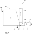
- the hot exhaust gases emerging from the turbine 13 are fed in combined operation via an exhaust gas duct 14 to a heat recovery steam generator 17 where they convert feed water supplied via a feed water inlet 19 into steam by heat exchange, which is discharged at a superheated steam outlet 20 .
- the cooled exhaust gases leave the heat recovery steam generator 17 via an exhaust gas outlet 18.
- the heat recovery steam generator 17 is part of a water/steam circuit (not shown) with a steam turbine, condenser, feed water tank and feed water pump.
- a secondary chimney 16 branches off from the exhaust gas duct 14 in front of the heat recovery steam generator 17 .
- a deflection flap 15 is arranged in the exhaust gas duct 14, which can be switched between two end positions. In one end position (in 1 shown in dashed lines) it allows the exhaust gases from the gas turbine to the heat recovery steam generator 17 to pass unhindered and at the same time blocks the secondary chimney 16 . This end position is used in the usual combined operation. In the other end position (in 1 drawn in solid) the connection to the heat recovery steam generator 17 is interrupted and the hot exhaust gases are deflected directly into the secondary chimney 16 .
- the deflection flap 15 is switched into this end position when switching from combined operation to single operation, in which only the gas turbine is used without a water/steam cycle 11 is in operation and generating electricity.
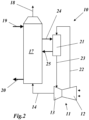
- the turbine 13 and possibly also the combustion chamber are further cooled with air taken from the compressor 12 at one or more points and according to 2 is fed via a compressed air line 22 to a downstream through-flow cooler 21 and cooled down there.
- the through-flow cooler 21 is connected to the heat recovery steam generator 17 via a feed water supply line 24 and a steam discharge line 25 .
- the heat recovery steam generator 17 is supplied with cold feed water via the feed water inlet 19 and with hot exhaust gases from the gas turbine 11 via the exhaust gas duct 14 .
- the feed water is heated through several stages, evaporates and leaves the heat recovery steam generator 17 via the superheated steam outlet 20 as superheated steam.
- the exhaust gases cool down as a result of this heat exchange process and leave the heat recovery steam generator 17 via the exhaust gas outlet 18.
- feedwater is removed from the heat recovery steam generator 17 and fed to the flow cooler 21 via the feedwater supply line 24, where it cools down the compressed air from the gas turbine 11.
- the steam generated in the once-through cooler 21 flows back to the heat recovery steam generator 17 via the steam discharge line 25, while the cooled-down air is routed back to the gas turbine 11 via the compressed air line 23 for cooling purposes.
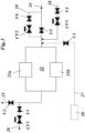
- the shut-off valve V5 in the feed water supply line 24 can be bypassed by a feed water bypass line 29, in which a shut-off valve V6 and a control valve CV2 are installed in series to ensure a smooth change in the feed water pressure when switching from single operation to combined operation.
- a shut-off valve V2 is inserted in the steam discharge line 25 leading to the heat recovery steam generator 17 .
- a steam discharge line 26 branches off, which diverts the steam in single operation, and in which a shut-off valve V1 and a control valve CV1 are installed one after the other.
- the feedwater flows from the heat recovery steam generator 17 in the feedwater supply line 24 through the open shut-off valve V5 at high pressure into the once-through cooler 21.
- the superheated steam is sent back to the overheated part of the heat recovery steam generator 17 via the steam discharge line 25 and the open shut-off valve V2 .
- the shut-off valve V1 is closed.
- feedwater is fed from a separate single-cycle feedwater system 30 via the feedwater supply line 27 at medium pressure via the isolation valve V3, which separates the single-cycle feedwater system 30 from the feedwater system of the heat recovery steam generator 17. Because of corrosion, it is essential that the feed water is provided at a temperature of 150°C in single operation, which is lower than in combined operation.
- the steam generated in the once-through cooler 21 flows out via the steam discharge line 26, the valves V1 and CV1 being used for switching and control purposes.
- the process parameters in combined operation and in single operation differ both in terms of pressure and temperature.
- the cold water mixing line 28 with the valves CV3 and V4 is provided for a gentle temperature transition when switching from combined operation to single operation.
- the feedwater bypass line 29 with the valves CV2 and V6 is there for a stepless change in the feedwater pressure.
- the procedure outlined is important to ensure that pressure overshoot and subcooling in the once-through chiller is minimal.
Landscapes
- Engineering & Computer Science (AREA)
- Chemical & Material Sciences (AREA)
- Combustion & Propulsion (AREA)
- Mechanical Engineering (AREA)
- General Engineering & Computer Science (AREA)
- Life Sciences & Earth Sciences (AREA)
- Sustainable Development (AREA)
- Sustainable Energy (AREA)
- Physics & Mathematics (AREA)
- Thermal Sciences (AREA)
- Engine Equipment That Uses Special Cycles (AREA)
Description
Die vorliegende Erfindung bezieht sich auf das Gebiet der Kraftwerkstechnik. Sie betrifft ein Verfahren zum Betrieb eines Kombikraftwerks gemäss dem Oberbegriff des Anspruchs 1 sowie ein Kombikraftwerk zur Durchführung des Verfahrens.The present invention relates to the field of power plant technology. It relates to a method for operating a combined cycle power plant according to the preamble of claim 1 and a combined cycle power plant for carrying out the method.
Um den Wirkungsgrad von Kombikraftwerken zu erhöhen, werden im Stand der Technik die Gasturbinen mit hohen Verdichtungsverhältnissen gefahren. Bei bekannten Gasturbinen wie z. B. dem Typ GT26 des Anmelders wird aus dem Verdichter der Gasturbine komprimierte Luft abgezweigt, um die Brennkammer und Teile der Turbine zu kühlen. Die beim Verdichten entstehenden hohen Temperaturen der abgezweigten Luft erfordert eine Kühlung, bevor die komprimierte Luft (Druckluft) als Kühlluft eingesetzt werden kann. Die Druckluft kann beispielsweise in einem oder mehreren Durchlaufkühler(n) (Once Through Cooler OTC) heruntergekühlt werden. In einem Kombikraftwerk wird dazu Wasser aus dem Abhitzedampferzeuger abgezweigt und zum Durchlaufkühler geschickt, um dort die Druckluft zu kühlen. Während dieses Prozesses wird im Durchlaufkühler Dampf erzeugt. Der überhitzte Dampf aus dem Durchlaufkühler wird zum Abhitzedampferzeuger zurückgeführt.In order to increase the efficiency of combined cycle power plants, the gas turbines are driven with high compression ratios in the prior art. In known gas turbines such. B. the type GT26 of the applicant, compressed air is diverted from the compressor of the gas turbine to cool the combustor and parts of the turbine. The high temperatures of the branched air that occur during compression require cooling before the compressed air (compressed air) can be used as cooling air. The compressed air can be cooled down, for example, in one or more through-flow cooler(s) (Once Through Cooler OTC). In a combined cycle power plant, water is diverted from the waste heat steam generator and sent to the flow cooler to cool the compressed air there. During this process, steam is generated in the once-through cooler. The superheated steam from the once-through cooler is returned to the heat recovery steam generator.
Es wäre nun wünschenswert, zur Erhöhung der Verfügbarkeit und Flexibilität des Betriebs ein Kombikraftwerk so auszugestalten und zu betreiben, dass es sowohl in einer mit zwei Kreisläufen (Combined Cycle CC) arbeitenden Betriebsart, als auch in einer mit nur einem Kreislauf (Single Cycle SC) arbeitenden Betriebsart betrieben werden kann.In order to increase the availability and flexibility of operation, it would now be desirable to design and operate a combined cycle power plant in such a way that it works both in an operating mode with two circuits (Combined Cycle CC) and in one with only one circuit (Single Cycle SC). working mode can be operated.
Wird ein Kombikraftwerk mit nur einem Kreislauf, dem Gasturbinenkreislauf, betrieben, bei welchem der Abhitzedampferzeuger nicht zur Verfügung steht, und wird das Kraftwerk von der einen Betriebsart in die andere überführt, ergeben sich die folgenden Probleme:
- Wie soll der Durchlaufkühler, insbesondere dessen Druck und Temperatur, gesteuert werden, wenn umgeschaltet wird?
- Wo soll bei der Betriebsart mit nur einem Kreislauf das Wasser für den Durchlaufkühler hergenommen werden?
- Was soll mit dem im Durchlaufkühler erzeugten Dampf geschehen?
- How should the once-through cooler, in particular its pressure and temperature, be controlled when switching over?
- Where is the water for the through-flow cooler to be taken from in the operating mode with only one circuit?
- What is to be done with the steam generated in the once-through cooler?
Obgleich die Betriebsart mit zwei Kreisläufen vom Standpunkt des Wirkungsgrades für den Betreiber interessanter ist als die Betriebsart mit nur einem Kreislauf, kann die letztere Bedeutung erlangen, wenn der Betreiber mehr Flexibilität beim Betrieb der Anlage und eine bessere Verfügbarkeit haben möchte, ohne dass die gesamte Anlage abgeschaltet werden muss. Die Betriebsart mit nur einem Kreislauf kann auch nützlich sein, wenn zunächst ein Kraftwerk mit nur einem Kreislauf errichtet wird, das später zu einem Kombikraftwerk erweitert wird.Although the two-loop mode of operation is more attractive to the operator than the single-loop mode from an efficiency standpoint, the latter can become important when the operator wants more flexibility in operating the plant and better availability without having to use the entire plant must be switched off. Single circuit mode can also be useful when initially building a single circuit power plant, which is later expanded to a combined cycle power plant.
Dokument
Dokument
Es ist Aufgabe der Erfindung, eine Betriebsverfahren für ein Kombikraftwerk anzugeben sowie ein Kombikraftwerk zur Durchführung des Verfahrens zu schaffen, welche die Flexibilität beim Betrieb der Anlage erhöhen und eine bessere Anlagenverfügbarkeit zur Folge haben.The object of the invention is to specify an operating method for a combined cycle power plant and to create a combined cycle power plant for carrying out the method, which increases the flexibility in operating the plant and results in better plant availability.
Die Aufgabe wird durch die Gesamtheit der Merkmale der unabhängigen Ansprüche gelöst.The object is achieved by the totality of the features of the independent claims.
Das beanspruchte Verfahren ist dadurch gekennzeichnet, dass beim Umschalten von einer zweiten Betriebsart (Kombibetrieb), bei der der Garturbinenkreislauf und der Wasser/Dampfkreislauf zur Energieerzeugung eingesetzt werden, zu einer ersten Betriebsart (Einfachbetrieb), bei der nur der Gasturbinenkreislauf zur Energieerzeugung eingesetzt wird, die heissen Abgase aus der Gasturbine sukzessive von dem Abhitzedampferzeuger weg in einen Nebenkamin umgeleitet werden, und umgekehrt, und dass zum Umleiten der heissen Abgase eine in dem von der Gasturbine zum Abhitzedampferzeuger führenden Abgaskanal angeordnete Umlenkklappe betätigt wird.The claimed method is characterized in that when switching from a second operating mode (combined operation), in which the gas turbine cycle and the water/steam cycle are used to generate energy, to a first operating mode (single operation), in which only the gas turbine cycle is used to generate energy, the hot exhaust gases from the gas turbine are successively diverted away from the heat recovery steam generator into a secondary chimney and vice versa, and in that a diverting flap arranged in the exhaust gas duct leading from the gas turbine to the heat recovery steam generator is actuated to divert the hot exhaust gases.
Vorzugsweise wird gleichzeitig die Abgabe von Dampf aus dem Durchlaufkühler an den Abhitzedampferzeuger zurückgefahren und der Dampf anderweitig verwendet wird, bzw. umgekehrt, wobei der vom Abhitzedampferzeuger abgezogene Dampf entweder in den Nebenkamin abgelassen oder der durch den Durchlaufkühler geführten Druckluft zugemischt oder einem luftgekühlten Kondensator zugeführt wird, um den Verlust an entmineralisiertem Wasser zu minimieren.Preferably, at the same time, the discharge of steam from the through-flow cooler to the waste-heat steam generator is reduced and the steam is used elsewhere, or vice versa, with the steam drawn off from the heat-recovery steam generator either being discharged into the side chimney or mixed with the compressed air fed through the through-flow cooler or fed to an air-cooled condenser to minimize the loss of demineralized water.
Gleichzeitig wird gemäss der vorliegend beanspruchten Erfindung auch die Zufuhr von Speisewasser aus dem Abhitzedampferzeuger zurückgefahren und durch eine anderweitige Zufuhr von Speisewasser ersetzt, bzw. umgekehrt, wobei in der Übergangsphase dem Speisewasser mittels einer separaten Kaltwassermischleitung kaltes Wasser zugemischt wird.At the same time, according to the presently claimed invention, the supply of feedwater from the heat recovery steam generator is reduced and replaced by another supply of feedwater, or vice versa, with cold water being mixed into the feedwater in the transition phase by means of a separate cold water mixing line.
Insbesondere wird die Zufuhr von Speisewasser aus dem Abhitzedampferzeuger mittels eines in einer Speisewasser-Bypassleitung angeordneten Regelventils zurückgefahren, nachdem die Versorgung des Durchlaufkühlers mit dem Speisewasser auf die Speisewasser-Bypassleitung umgeschaltet worden ist, bzw. umgekehrt.In particular, the supply of feedwater from the heat recovery steam generator is reduced by means of a control valve arranged in a feedwater bypass line after the supply of feedwater to the flow cooler has been switched to the feedwater bypass line, or vice versa.
Zur anderweitigen Zufuhr von Speisewasser wird gemäss der vorliegend beanspruchten Erfindung ein separates Ein-Zyklus-Speisewassersystem herangezogen.According to the presently claimed invention, a separate single-cycle feedwater system is used to supply feedwater from other sources.
Eine Ausgestaltung des Kombikraftwerks nach der Erfindung zeichnet sich dadurch aus, dass zum Umleiten der heissen Abgase vom Abhitzedampferzeuger zum Nebenkamin im Abgaskanal eine Umlenkklappe angeordnet ist.An embodiment of the combined cycle power plant according to the invention is characterized in that a deflection flap is arranged in the exhaust gas duct to divert the hot exhaust gases from the heat recovery steam generator to the secondary chimney.
Insbesondere ist in der ersten Dampfableitung ein erstes Absperrventil angeordnet, und es zweigt von der ersten Dampfableitung vor dem ersten Absperrventil eine für die erste Betriebsart vorgesehene zweite Dampfableitung ab.In particular, a first shut-off valve is arranged in the first steam discharge line, and a second steam discharge line provided for the first operating mode branches off from the first steam discharge line upstream of the first shut-off valve.
Gemäss einer Weiterbildung sind in der zweiten Dampfableitung hintereinander ein zweites Absperrventil und ein erstes Regelventil angeordnet.According to a development, a second shut-off valve and a first control valve are arranged one behind the other in the second vapor discharge line.
Eine andere Ausgestaltung ist dadurch gekennzeichnet, dass in der ersten Speisewasserzuleitung ein drittes Absperrventil angeordnet ist, und dass zur Umgehung des dritten Absperrventils eine Speisewasser-Bypassleitung vorgesehen ist, in der hintereinander ein viertes Absperrventil und ein zweites Regelventil angeordnet sind, wobei in die erste Speisewasserleitung zwischen der Speisewasser-Bypassleitung und dem Durchflusskühler eine Kaltwassermischleitung einmündet, und in der Kaltwassermischleitung hintereinander ein fünftes Absperrventil und ein drittes Regelventil angeordnet sind.Another embodiment is characterized in that a third shut-off valve is arranged in the first feed water supply line, and in that a feed water bypass line is provided to bypass the third shut-off valve, in which a fourth shut-off valve and a second control valve are arranged one after the other, with the first feed water line a cold water mixing line opens out between the feed water bypass line and the flow cooler, and a fifth shut-off valve and a third control valve are arranged one behind the other in the cold water mixing line.
Weiterhin ist es von Vorteil, wenn in die erste Speisewasserleitung zwischen der Speisewasser-Bypassleitung und dem Durchflusskühler eine von einem separaten Ein-Zyklus-Speisewassersystem kommende zweite Speisewasserleitung einmündet, und in der zweiten Speisewasserleitung ein sechstes Absperrventil angeordnet ist.Furthermore, it is advantageous if a second feedwater line coming from a separate one-cycle feedwater system opens into the first feedwater line between the feedwater bypass line and the flow cooler, and a sixth shut-off valve is arranged in the second feedwater line.
Die Erfindung soll nachfolgend anhand von Ausführungsbeispielen im Zusammenhang mit der Zeichnung näher erläutert werden. Es zeigen
- Fig. 1
- einen Teilaspekt eines Kombikraftwerks für die Durchführung des erfindungsgemässen Verfahrens mit einem einer Gasturbine nachgeschalteten Abhitzedampferzeuger und einem Nebenkamin zur Umlenkung der heissen Abgase;
- Fig. 2
- einen weiteren Teilaspekt des Kombikraftwerks mit einem Durchlaufkühler zur Kühlung der komprimierten Kühlluft, der im Kombibetrieb an den Abhitzedampferzeuger angeschlossen ist und
- Fig. 3
- ausschnittweise eine Anschlusskonfiguration des Durchlaufkühlers aus
Fig. 2 , die eine Umschaltung zwischen Kombibetrieb und ausschliesslichem Gasturbinen-Betrieb gemäss der Erfindung ermöglicht.
- 1
- a partial aspect of a combined cycle power plant for carrying out the method according to the invention with a heat recovery steam generator downstream of a gas turbine and a secondary chimney for deflecting the hot exhaust gases;
- 2
- a further aspect of the combined cycle power plant with a flow cooler for cooling the compressed cooling air, which is connected to the heat recovery steam generator in combined operation and
- 3
- A section of a connection configuration of the flow-through cooler
2 , which allows switching between combined operation and exclusive gas turbine operation according to the invention.
Die Erfindung stellt ein Konzept und System für ein Kombikraftwerk zur Verfügung, welches eine Umschaltung zwischen zwei Betriebsarten, nämlich zwischen dem herkömmlichen Kombibetrieb mit Gasturbine und Dampfturbine und dem Einfachbetrieb nur mit der Gasturbine, ohne Unterbrechung der Energieerzeugung ermöglicht.The invention provides a concept and system for a combined cycle power plant which enables switching between two operating modes, namely between the conventional combined operation with gas turbine and steam turbine and single operation with only the gas turbine, without interrupting the generation of energy.
Dazu wird ausgegangen von einer Konfiguration des Kombikraftwerks, wie sie in
Die aus der Turbine 13 austretenden heissen Abgase werden im Kombibetrieb über einen Abgaskanal 14 einem Abhitzedampferzeuger 17 zugeführt, wo sie über einen Speisewassereinlass 19 zugeführtes Speisewasser durch Wärmeaustausch in Dampf verwandeln, der an einem Heissdampfauslass 20 abgegeben wird. Die abgekühlten Abgase verlassen den Abhitzedampferzeuger 17 über einen Abgasauslass 18. Der Abhitzedampferzeuger 17 ist Teil eines (nicht gezeigten) Wasser/Dampf-Kreislaufs mit Dampfturbine, Kondensator, Speisewasserbehälter und Speisewasserpumpe.The hot exhaust gases emerging from the
Von dem Abgaskanal 14 zweigt vor dem Abhitzedampferzeuger 17 ein Nebenkamin 16 ab. Am Abzweigpunkt ist im Abgaskanal 14 eine Umlenkklappe 15 angeordnet, die zwischen zwei Endstellungen umschaltbar ist. In der einen Endstellung (in
Beim vorliegenden Kombikraftwerk wird weiterhin die Turbine 13 und ggf. auch die Brennkammer mit Luft gekühlt, die dem Kompressor 12 an einer oder mehreren Stellen entnommen und gemäss
Auf halbem Wege, nach den Vorwärmer-Stufen, wird aus dem Abhitzedampferzeuger 17 Speisewasser entnommen und über die Speisewasserzuleitung 24 dem Durchlaufkühler 21 zugeführt, wo es die verdichtete Luft aus der Gasturbine 11 herunterkühlt. Der im Durchlaufkühler 21 erzeugte Dampf strömt über die Dampfableitung 25 zum Abhitzedampferzeuger 17 zurück, während die heruntergekühlte Luft über die Druckluftleitung 23 zu Kühlungszwecken zurück zur Gasturbine 11 geleitet wird.Halfway, after the preheater stages, feedwater is removed from the heat
Um in der Konfiguration mit dem Durchlaufkühler 21 und dem Abhitzedampferzeuger 17 eine Umschaltung zwischen Kombibetrieb und Einfachbetrieb ohne Lastabsenkung der Gasturbine zu ermöglichen, ist eine Anordnung gemäss dem Ausführungsbeispiel der
Im Kombibetrieb (Gasturbine und Dampfturbine) strömt das Speisewasser vom Abhitzedampferzeuger 17 in der Speisewasserzuleitung 24 durch das offene Absperrventil V5 mit hohem Druck in den Durchlaufkühler 21. Der überhitzte Dampf wird über die Dampfableitung 25 und das offene Absperrventil V2 zum überhitzten Teil des Abhitzedampferzeugers 17 zurückgeschickt. Das Absperrventil V1 ist dabei geschlossen.In combined operation (gas turbine and steam turbine), the feedwater flows from the heat
Im Einfachbetrieb (nur mit der Gasturbine) wird Speisewasser aus einem separaten Ein-Zyklus-Speisewassersystem 30 über die Speisewasserzuleitung 27 bei mittlerem Druck über das Absperrventil V3 eingespeist, welches das Ein-Zyklus-Speisewassersystem 30 vom Speisewassersystem des Abhitzedampferzeugers 17 trennt. Wegen der Korrosion ist es dabei wesentlich, dass das Speisewasser beim Einfachbetrieb mit einer Temperatur von 150°C bereitgestellt wird, die im Vergleich zum Kombibetrieb niedriger ist. Der im Durchlaufkühler 21 erzeuget Dampf strömt über die Dampfableitung 26 ab, wobei die Ventile V1 und CV1 für Umschalt- und Regelzwecke eingesetzt werden.In single operation (only with the gas turbine), feedwater is fed from a separate single-cycle feedwater system 30 via the
Die Prozessparameter im Kombibetrieb und im Einfachbetrieb unterscheiden sich sowohl hinsichtlich des Drucks als auch hinsichtlich der Temperatur. Für einen sanften Temperaturübergang beim Umschalten von Kombibetrieb auf Einfachbetrieb ist die Kaltwassermischleitung 28 mit den Ventilen CV3 und V4 vorgesehen. Für eine stufenlose Änderung des Speisewasserdruckes ist die Speisewasser-Bypassleitung 29 mit den Ventilen CV2 und V6 da.The process parameters in combined operation and in single operation differ both in terms of pressure and temperature. The cold
Der im Einfachbetrieb über die Dampfableitung 26 abgegebene Dampf aus dem Durchlaufkühler 21 kann auf unterschiedliche Weise verwendet werden:
- Der Dampf wird entweder in
den Nebenkamin 16 abgelassen; - oder er wird in
die zum Durchlaufkühler 21führende Druckluftleitung 22 injiziert; - oder er wird einem (in den Figuren nicht gezeigten) luftgekühlten Kondensator zugeführt, um die Verluste an entmineralisiertem Wasser zu minimieren.
- The steam is either discharged into the
side chimney 16; - or it is injected into the
compressed air line 22 leading to the through-flow cooler 21; - or it is fed to an air-cooled condenser (not shown in the figures) to minimize losses of demineralized water.
Für die Umschaltung vom Kombibetrieb zum Einfachbetrieb bei laufender Stromerzeugung ist zunächst der Nebenkamin 16 mit Umlenkklappe 15 notwendig. Weiterhin ist zu berücksichtigen, dass die Prozessparameter sich bei Einfachbetrieb und Kombibetrieb voneinander unterscheiden. Insbesondere sind die Speisewasser- und Dampfdrücke sowie Speisewasser- und möglicherweise die Dampftemperaturen am Durchlaufkühler im Kombibetrieb am höchsten. Daher müssen beim Umschalten vom Kombibetrieb zum Einfachbetrieb die folgenden Schritte eingehalten werden:
- Um Temperaturänderungen beim Speisewasser zu vermeiden, wird zunächst parallel zu den nachfolgenden Schritten die Umlenkklappe nach und nach geschlossen (in die in
Fig. 1 durchgezogen eingezeichnete Endstellung geschwenkt). - Es wird begonnen, das Absperrventil V2 in
der Dampfableitung 25zum Abhitzedampferzeuger 17 zu schliessen, so dass der Druck vor dem Regelventil CV1 in der anderen Dampfableitung 26 anfänglich gleich dem Druck im Kombibetrieb ist. Wenn das Absperrventil V2 vollständig geschlossen ist, sollte der Druck auf den Solldruck bei Einfachbetrieb eingeschwungen sein. - Es werden die Ventile V4 und CV3 der Kaltwassermischleitung 28 geöffnet und nach und nach die Speisewassertemperatur mit mässiger Änderungsrate vom Niveau des Kombibetriebs auf das Niveau des Einfachbetriebs abgesenkt, um die Temperatur der Gasturbinen-Kühlluft stabil zu halten.
- Nach und nach werden bei offen gehaltenen Absperrventil V5 die Ventile CV2 und V6 der Speisewasser-
Bypassleitung 29 geöffnet. - Anschliessend wird das Absperrventil V5 geschlossen.
- Dann werden nach und nach gleichzeitig die beiden Regelventile CV2 und CV3 geschlossen und dabei die Speisewassertemperatur auf dem Niveau des Einfachbetriebs gehalten. Das Regelventil CV" wird mit einem gesteuerten Gradienten geschlossen. Zu gleicher Zeit wird das Absperrventil V3 in
der Speisewasserzuleitung 27 geöffnet.
- In order to avoid temperature changes in the feed water, the diverter flap is first gradually closed (into the in
1 swung end position drawn solid). - The shut-off valve V2 in the
steam discharge line 25 to the heatrecovery steam generator 17 to close so that the pressure before the control valve CV1 in the othervapor discharge line 26 is initially equal to the pressure in combined operation. When the shut-off valve V2 is fully closed, the pressure should have settled to the target pressure for single operation. - Valves V4 and CV3 of chilled
water mixing line 28 are opened and gradually the feedwater temperature is lowered from the combined mode level to the single mode level at a moderate rate of change to keep the gas turbine cooling air temperature stable. - The valves CV2 and V6 of the feed
water bypass line 29 are gradually opened while the shut-off valve V5 is kept open. - The shut-off valve V5 is then closed.
- The two control valves CV2 and CV3 are then gradually closed at the same time while the feed water temperature is kept at the level of single operation. The control valve CV" is closed with a controlled gradient. At the same time the shut-off valve V3 in the feed
water supply line 27 is opened.
Die beschriebene Vorgangsweise ist wichtig, um sicherzustellen, dass das Überschwingen des Druckes und die Unterkühlung im Durchlaufkühler minimal sind.The procedure outlined is important to ensure that pressure overshoot and subcooling in the once-through chiller is minimal.
Insgesamt zeichnet sich die Erfindung durch folgende Charakteristika und Vorteile aus:
- 1. Ein Kombikraftwerk mit einem oder mehreren Durchlaufkühler(n) für die Gasturbinen-Kühlluft und Nebenkamin mit Umlenkklappe kann vom Kombibetrieb zum Einfachbetrieb umgeschaltet werden, ohne die Last der Gasturbine abzusenken und die Kühllufttemperaturen der Gasturbine instabil werden zu lassen.
- 2. Das Kombikraftwerk weist dazu folgende Untersysteme auf:
- ∘ Ein Ein-Zyklus-Speisewassersystem für den Einfachbetrieb
- ∘ Ein Dampfsystem zur Ableitung des bei Einfachbetrieb erzeugten Dampfes.
- ∘ Ein Umschaltsystem, das einen sanften Übergang in Druck und Temperatur zwischen Einfachbetrieb und Kombibetrieb ermöglicht.
- 1. A combined cycle power plant with one or more once-through cooler(s) for the gas turbine cooling air and side chimney with a reversing damper can be switched from combined operation to single operation without lowering the load on the gas turbine and causing the gas turbine cooling air temperatures to become unstable.
- 2. The combined cycle power plant has the following subsystems:
- ∘ A one cycle feed water system for single operation
- ∘ A steam system to remove the steam generated during single operation.
- ∘ A switching system that allows a smooth transition in pressure and temperature between single operation and combined operation.
- 1010
- Kombikraftwerkcombined cycle power plant
- 1111
- Gasturbinegas turbine
- 1212
- Verdichtercompressor
- 1313
- Turbineturbine
- 1414
- Abgaskanalexhaust duct
- 1515
- Umlenkklappediverter flap
- 1616
- Nebenkaminside fireplace
- 1717
- Abhitzedampferzeuger (HRSG)Heat recovery steam generator (HRSG)
- 1818
- Abgasauslassexhaust outlet
- 1919
- Speisewassereinlassfeedwater inlet
- 2020
- Heissdampfauslasshot steam outlet
- 2121
- Durchlaufkühler (OTC)Through-flow cooler (OTC)
- 21a21a
- Niederdruck-DurchlaufkühlerLow-pressure once-through cooler
- 21b21b
- Hochdruck-DurchlaufkühlerHigh-pressure once-through cooler
- 22,2322.23
- Druckluftleitungcompressed air line
- 2424
- Speisewasserzuleitung (OTC)feed water supply line (OTC)
- 2525
- Dampfableitung (OTC)Vapor Dissipation (OTC)
- 2626
- Dampfableitung (SC)Steam Drain (SC)
- 2727
- Speisewasserzuleitung (SC)feed water supply line (SC)
- 2828
- Kaltwassermischleitungcold water mixing line
- 2929
- Speisewasser-BypassleitungFeedwater bypass line
- 3030
- Ein-Zyklus-SpeisewassersystemOne cycle feed water system
- V1,..,V6V1,..,V6
- VentilValve
- CV1,..,CV3CV1,..,CV3
- Regelventilcontrol valve
Claims (16)
- Method for operating a combined cycle power plant (10) which comprises a gas turbine (11) having a compressor (12) and a turbine (13); a waste heat steam generator (17) connected downstream of the gas turbine (11) for generating steam in a water/steam circuit; and at least one continuous cooler (21) through which flows compressed air, compressed in the compressor (12), intended for cooling the gas turbine (11), and which converts feed water (24) supplied from the waste heat steam generator (17) during cooling into steam and releases said steam to the waste heat steam generator (17); characterized in that the combined cycle power plant (10), to make operation flexible without decreasing the load of the gas turbine (11), is switched between a first operating mode (single mode), in which only the gas turbine circuit is used for power generation, and a second operating mode (combined operation), in which the gas turbine circuit and the water/steam circuit are used for power generation; wherein, upon switching from the second operating mode to the first operating mode, the hot exhaust gases from the gas turbine (11) are successively diverted away from the waste heat steam generator (17) into a secondary chimney (16), and the supply of feed water from the waste heat steam generator (17) is simultaneously reversed and replaced by another supply of feed water, or vice versa; wherein a separate single-cycle feed water system (30) is used for the other supply of feed water; and wherein, in the transition phase, cold water is admixed with the feed water by means of a separate cold water mixing (28) line.
- Method according to the preceding claim, characterized in that a deflection flap (15), arranged in the exhaust gas conduit (14) leading from the gas turbine (11) to the waste heat steam generator (17), is actuated to divert the hot exhaust gases.
- Method according to any of the preceding claims, characterized in that, upon switching from the second operating mode to the first operating mode, the delivery of steam from the continuous cooler (21) to the waste heat steam generator (17) is simultaneously reversed, and the steam is used in other ways; or, upon switching from the first operating mode to the second operating mode, the delivery of steam from the continuous cooler (21) to the waste heat steam generator is simultaneously started up.
- Method according to the preceding claim, characterized in that the steam removed from the waste heat steam generator (17) is discharged into the secondary chimney (16).
- Method according to claim 3, characterized in that the steam removed from the waste heat steam generator (17) is admixed with the compressed air guided through the continuous cooler (21).
- Method according to claim 3, characterized in that the steam removed from the waste heat steam generator (17) is supplied to an air-cooled condenser in order to minimize the loss of demineralized water.
- Method according to any one of the preceding claims, characterized in that the supply of feed water from the waste heat steam generator (17) is reversed, by means of a control valve (CV2) arranged in a feed water bypass line (29), after the supply of the continuous cooler (21) with the feed water has been switched to the feed water bypass line (29), or vice versa.
- A combined cycle power plant for implementing the method according to claim 1, comprising a gas turbine (11) having a compressor (12) and a turbine (13); a waste heat steam generator (17), downstream of the gas turbine (11), for generating steam in a water/steam circuit; and a continuous cooler (21) through which flows compressed air, compressed in the compressor (12), intended for cooling the gas turbine (11), and which converts feed water supplied via a feed water feed line (24) from the waste heat steam generator (17) during cooling into steam, and releases said steam to the waste heat steam generator (17) via a first steam discharge line (25); wherein the hot exhaust gases of the gas turbine (11) are guided via an exhaust gas conduit (14) to the waste heat steam generator (17); wherein a secondary chimney (16) branches off from the exhaust gas conduit (14); and wherein means are arranged for reversing the supply of feed water from the waste heat steam generator and for otherwise supplying feed water to the continuous cooler, as well as a cold water mixing line (28) for supplying cold water to the feed water; wherein the means for otherwise supplying feed water to the continuous cooler comprise a single cycle feed water system (30).
- Combined cycle power plant according to claim 8, characterized in that a deflection flap (15) for diverting the hot exhaust gases from the waste heat steam generator (17) to the secondary chimney (16) is arranged in the exhaust gas conduit (14).
- Combined cycle power plant according to claim 8 or 9, characterized in that a first shut-off valve (V2) is arranged in the first steam discharge line (25), and in that a second steam discharge line (26), provided for a first operating mode, branches off from the first steam discharge line (25) before the first shut-off valve (V2).
- Combined cycle power plant according to the preceding claim, characterized in that a second shut-off valve (V1) and a first regulating valve (CV1) are arranged in succession in the second steam discharge line (26).
- Combined cycle power plant according to any one of claims 8 to 11, characterized in that a third shut-off valve (V5) is arranged in the first feed water supply line (24), and in that a feed water bypass line (29), in which a fourth shut-off valve (V6) and a second regulating valve (CV2) are arranged in succession, is provided in order to bypass the third shut-off valve (V5).
- Combined cycle power plant according to the preceding claim, characterized in that the cold water mixing line (28) opens into the first feed water line (24) between the feed water bypass line (29) and the continuous cooler (21).
- Combined cycle power plant according to the preceding claim, characterized in that a fifth shut-off valve (V4) and a third regulating valve (CV3) are arranged in succession in the cold water mixing line (28).
- Combined cycle power plant according to claim 12, characterized in that a second feed water line (27), coming from the separate single cycle feed water system (30), opens into the first feed water line (24) between the feed water bypass line (29) and the continuous cooler (21).
- Combined cycle power plant according to claim 15, characterized in that a sixth shut-off valve (V3) is arranged in the second feed water line (27).
Applications Claiming Priority (1)
| Application Number | Priority Date | Filing Date | Title |
|---|---|---|---|
| CH14062007 | 2007-09-07 |
Publications (4)
| Publication Number | Publication Date |
|---|---|
| EP2067940A2 EP2067940A2 (en) | 2009-06-10 |
| EP2067940A3 EP2067940A3 (en) | 2013-06-19 |
| EP2067940B1 EP2067940B1 (en) | 2019-10-02 |
| EP2067940B2 true EP2067940B2 (en) | 2023-02-15 |
Family
ID=39301533
Family Applications (1)
| Application Number | Title | Priority Date | Filing Date |
|---|---|---|---|
| EP08162627.7A Active EP2067940B2 (en) | 2007-09-07 | 2008-08-19 | Method for operating a combined cycle power plant, and also combined-cycle power plant for carrying out the method |
Country Status (3)
| Country | Link |
|---|---|
| US (2) | US8146366B2 (en) |
| EP (1) | EP2067940B2 (en) |
| JP (1) | JP5558686B2 (en) |
Families Citing this family (13)
| Publication number | Priority date | Publication date | Assignee | Title |
|---|---|---|---|---|
| US9435534B2 (en) * | 2009-08-31 | 2016-09-06 | Holistic Engineering Inc | Energy-recovery system for a production plant |
| JP5540209B2 (en) * | 2009-11-17 | 2014-07-02 | 独立行政法人農業・食品産業技術総合研究機構 | Heating medium generation method |
| EP2385223A1 (en) * | 2010-05-04 | 2011-11-09 | Thermal PowerTec GmbH | Procedure for the increase of the efficiency of gas and steam turbine power plants |
| ES2578294T3 (en) | 2011-09-07 | 2016-07-22 | Alstom Technology Ltd. | Operating procedure of a combined cycle power plant |
| CH705929A1 (en) | 2011-12-22 | 2013-06-28 | Alstom Technology Ltd | A method of operating a combined cycle power plant. |
| US9429044B2 (en) | 2012-01-13 | 2016-08-30 | Alstom Technology Ltd | Supercritical heat recovery steam generator reheater and supercritical evaporator arrangement |
| EP2775107A1 (en) | 2013-03-06 | 2014-09-10 | Alstom Technology Ltd | Method for starting-up and operating a combined-cycle power plant |
| EP2863033B1 (en) * | 2013-10-21 | 2019-12-04 | Ansaldo Energia IP UK Limited | Gas turbine with flexible air cooling system and method for operating a gas turbine |
| GB2524582B (en) * | 2014-03-28 | 2016-07-20 | Mitsubishi Hitachi Power Sys | Combined cycle gas turbine plant |
| SE539758C2 (en) | 2014-12-04 | 2017-11-21 | Powercell Sweden Ab | Catalytic burner arrangement |
| US11268409B2 (en) | 2017-11-09 | 2022-03-08 | Mitsubishi Power Americas, Inc. | Over-powering |
| JP6965167B2 (en) * | 2018-01-12 | 2021-11-10 | 三菱パワー株式会社 | Gas turbine cogeneration system and its operation switching method |
| US11719156B2 (en) | 2021-03-30 | 2023-08-08 | Doosan Enerbility Co., Ltd. | Combined power generation system with feedwater fuel preheating arrangement |
Citations (1)
| Publication number | Priority date | Publication date | Assignee | Title |
|---|---|---|---|---|
| EP0773349A1 (en) † | 1995-11-10 | 1997-05-14 | Asea Brown Boveri Ag | Cooling-air cooling unit for power plants |
Family Cites Families (33)
| Publication number | Priority date | Publication date | Assignee | Title |
|---|---|---|---|---|
| US3953966A (en) * | 1974-08-08 | 1976-05-04 | Westinghouse Electric Corporation | Combined cycle electric power plant having a control system which enables dry steam generator operation during gas turbine operation |
| AT352479B (en) * | 1976-03-08 | 1979-09-25 | Kraftwerk Union Ag | PROTECTIVE DEVICE FOR THE EXHAUST GAS DUCT OF A GAS TURBINE IN A COMBINED GAS TURBINE-STEAM PLANT |
| US4362013A (en) * | 1980-04-04 | 1982-12-07 | Hitachi, Ltd. | Method for operating a combined plant |
| DE59205642D1 (en) | 1991-06-21 | 1996-04-18 | Siemens Ag | Method and system for operating a gas turbine |
| US5267434A (en) * | 1992-04-14 | 1993-12-07 | Siemens Power Corporation | Gas turbine topped steam plant |
| DE4344857A1 (en) * | 1993-12-29 | 1995-07-06 | Abb Management Ag | Method and device for operating a gas turbine in a simple and a combined cycle with a steam turbine |
| US5513488A (en) * | 1994-12-19 | 1996-05-07 | Foster Wheeler Development Corporation | Power process utilizing humidified combusted air to gas turbine |
| DE19508018A1 (en) * | 1995-03-07 | 1996-09-12 | Abb Management Ag | Process for operating a power plant |
| DE19535228C2 (en) * | 1995-09-22 | 2003-05-08 | Alstom | Process for operating a power plant |
| DE19636107C1 (en) | 1996-09-05 | 1998-01-08 | Siemens Ag | Flue-gas duct for combined gas-and steam-turbine plant |
| DE19645322B4 (en) * | 1996-11-04 | 2010-05-06 | Alstom | Combined power plant with a forced once-through steam generator as a gas turbine cooling air cooler |
| DE59803133D1 (en) * | 1997-05-16 | 2002-03-28 | Siemens Ag | GAS AND STEAM TURBINE SYSTEM AND METHOD FOR COOLING THE COOLANT OF THE GAS TURBINE OF SUCH A SYSTEM |
| ES2207949T3 (en) * | 1998-05-06 | 2004-06-01 | Siemens Aktiengesellschaft | INSTALLATION OF GAS AND STEAM TURBINES. |
| DE19832294C1 (en) * | 1998-07-17 | 1999-12-30 | Siemens Ag | Gas-and-steam turbine installation with integrated fossil fuel gasification |
| DE19901656A1 (en) * | 1999-01-18 | 2000-07-20 | Abb Alstom Power Ch Ag | Regulating temp. at outlet of steam superheater involves spraying water into superheater near steam inlet; water can be sprayed into wet, saturated or superheated steam |
| DE10041413B4 (en) | 1999-08-25 | 2011-05-05 | Alstom (Switzerland) Ltd. | Method for operating a power plant |
| JP4209069B2 (en) * | 2000-04-18 | 2009-01-14 | 三菱重工業株式会社 | Turbine equipment |
| DE10022243A1 (en) * | 2000-05-08 | 2002-02-21 | Alstom Power Nv | Process for operating a combined cycle power plant and combined cycle power plant for carrying out the process |
| DE10032625C1 (en) * | 2000-07-07 | 2001-08-02 | Mvv En Ag | Method and device for the simultaneous generation of hot and hot gas by means of combined heat and power |
| DE10064263A1 (en) * | 2000-12-22 | 2002-07-04 | Alstom Switzerland Ltd | Fluid machine and method of operation |
| EP1262638A1 (en) * | 2001-05-31 | 2002-12-04 | Siemens Aktiengesellschaft | Device for cooling of the cooling fluid of a gas turbine and gas and steam turbine plant with such a device |
| JP4004800B2 (en) * | 2002-01-10 | 2007-11-07 | 株式会社東芝 | Combined cycle power generation system |
| JP2004156442A (en) * | 2002-07-25 | 2004-06-03 | General Electric Co <Ge> | Cooling air system for combined cycle power plant and method thereof |
| DE10303341A1 (en) | 2003-01-29 | 2004-08-26 | Alstom Technology Ltd | Air cooler for power plant has casing around helical pipe bundle, first volume that forms inner casing separate from pressure vessel enclosed by cylindrical outer casing with annular gap between them |
| US6922984B2 (en) * | 2003-08-27 | 2005-08-02 | Valero Refining Company - California | Heat recovery circuit |
| WO2005042929A1 (en) * | 2003-10-30 | 2005-05-12 | Alstom Technology Ltd | Power plant |
| JP4469222B2 (en) * | 2004-05-19 | 2010-05-26 | 東京電力株式会社 | Combined power plant |
| US7367177B2 (en) * | 2004-12-14 | 2008-05-06 | Siemens Power Generation, Inc. | Combined cycle power plant with auxiliary air-cooled condenser |
| US20060254280A1 (en) * | 2005-05-12 | 2006-11-16 | Siemens Westinghouse Power Corporation | Combined cycle power plant using compressor air extraction |
| US20060272334A1 (en) * | 2005-06-01 | 2006-12-07 | Pavol Pranda | Practical method for improving the efficiency of cogeneration system |
| JP4811991B2 (en) * | 2005-07-06 | 2011-11-09 | 株式会社日立製作所 | High humidity gas turbine equipment |
| US7780152B2 (en) * | 2006-01-09 | 2010-08-24 | Hydroflame Technologies, Llc | Direct combustion steam generator |
| EP1808588A1 (en) * | 2006-01-14 | 2007-07-18 | Thermal PowerTec GmbH | Augmentation of power output and efficiency in gas turbine and combined cycle plants |
-
2008
- 2008-08-19 EP EP08162627.7A patent/EP2067940B2/en active Active
- 2008-08-26 US US12/198,359 patent/US8146366B2/en not_active Expired - Fee Related
- 2008-09-03 JP JP2008225440A patent/JP5558686B2/en not_active Expired - Fee Related
-
2012
- 2012-02-29 US US13/408,140 patent/US8516787B2/en not_active Expired - Fee Related
Patent Citations (1)
| Publication number | Priority date | Publication date | Assignee | Title |
|---|---|---|---|---|
| EP0773349A1 (en) † | 1995-11-10 | 1997-05-14 | Asea Brown Boveri Ag | Cooling-air cooling unit for power plants |
Also Published As
| Publication number | Publication date |
|---|---|
| EP2067940A2 (en) | 2009-06-10 |
| US20090064656A1 (en) | 2009-03-12 |
| JP2009062985A (en) | 2009-03-26 |
| JP5558686B2 (en) | 2014-07-23 |
| US8516787B2 (en) | 2013-08-27 |
| EP2067940B1 (en) | 2019-10-02 |
| EP2067940A3 (en) | 2013-06-19 |
| US8146366B2 (en) | 2012-04-03 |
| US20120167546A1 (en) | 2012-07-05 |
Similar Documents
| Publication | Publication Date | Title |
|---|---|---|
| EP2067940B2 (en) | Method for operating a combined cycle power plant, and also combined-cycle power plant for carrying out the method | |
| DE10041413B4 (en) | Method for operating a power plant | |
| EP0819209B1 (en) | Method of operating a waste-heat steam generator, and a waste-heat steam generator operated by this method | |
| EP0563553B1 (en) | Air cooling of turbines | |
| EP2480762B1 (en) | Power plant comprising overload control valve | |
| EP2067941A2 (en) | Combined cycle power plant with exhaust gas recycling and CO2 separation, and also method for operating such a combined cycle power plant | |
| DE10236324A1 (en) | Turbine blade cooling method for gas storage power plants, involves allowing cooling gas into turbine recuperator at predetermined temperature in fresh gas path, at standard operating conditions | |
| DE4213023A1 (en) | Process for operating a gas turbine group | |
| EP2196633A1 (en) | Power plant with a turbine unit and a generator | |
| EP1795725A1 (en) | Gas turbine with cooling air cooling | |
| EP0666412B1 (en) | Method for cooling the cooling air for a gasturbine | |
| EP2326800B1 (en) | Steam power assembly for creating electrical energy | |
| EP2798164A2 (en) | Method for operating a gas and steam turbine system for frequency assistance | |
| WO1998013588A1 (en) | Steam turbine, steam turbine plant and method of cooling a steam turbine | |
| EP3741971A1 (en) | Micro gas turbine assembly | |
| WO1992020905A1 (en) | Gas-turbine/steam-turbine installation | |
| DE10155508C5 (en) | Method and device for generating electrical energy | |
| EP2556218B1 (en) | Method for quickly connecting a steam generator | |
| EP1854964A1 (en) | Use of the steam turbine for primary frequency control in power generating plants | |
| EP1801363A1 (en) | Power plant | |
| DE2512774A1 (en) | Gas turbine water heating system - uses combination of exhaust gas heat and steam counter pressure (NL240976) | |
| EP1896697B1 (en) | Method of starting up a gas and steam turbine plant | |
| EP1904731B1 (en) | Combined gas and steam turbine installation and method of operating same | |
| EP3759330B1 (en) | Extended gas turbine process having an expander | |
| EP2426337A1 (en) | Device for fuel preheating and method for fuel preheating |
Legal Events
| Date | Code | Title | Description |
|---|---|---|---|
| PUAI | Public reference made under article 153(3) epc to a published international application that has entered the european phase |
Free format text: ORIGINAL CODE: 0009012 |
|
| AK | Designated contracting states |
Kind code of ref document: A2 Designated state(s): AT BE BG CH CY CZ DE DK EE ES FI FR GB GR HR HU IE IS IT LI LT LU LV MC MT NL NO PL PT RO SE SI SK TR |
|
| AX | Request for extension of the european patent |
Extension state: AL BA MK RS |
|
| PUAL | Search report despatched |
Free format text: ORIGINAL CODE: 0009013 |
|
| AK | Designated contracting states |
Kind code of ref document: A3 Designated state(s): AT BE BG CH CY CZ DE DK EE ES FI FR GB GR HR HU IE IS IT LI LT LU LV MC MT NL NO PL PT RO SE SI SK TR |
|
| AX | Request for extension of the european patent |
Extension state: AL BA MK RS |
|
| RIC1 | Information provided on ipc code assigned before grant |
Ipc: F01K 23/10 20060101AFI20130514BHEP Ipc: F22B 1/18 20060101ALI20130514BHEP |
|
| 17P | Request for examination filed |
Effective date: 20131022 |
|
| RBV | Designated contracting states (corrected) |
Designated state(s): AT BE BG CH CY CZ DE DK EE ES FI FR GB GR HR HU IE IS IT LI LT LU LV MC MT NL NO PL PT RO SE SI SK TR |
|
| AKX | Designation fees paid |
Designated state(s): AT BE BG CH CY CZ DE DK EE ES FI FR GB GR HR HU IE IS IT LI LT LU LV MC MT NL NO PL PT RO SE SI SK TR |
|
| RAP1 | Party data changed (applicant data changed or rights of an application transferred) |
Owner name: GENERAL ELECTRIC TECHNOLOGY GMBH |
|
| GRAP | Despatch of communication of intention to grant a patent |
Free format text: ORIGINAL CODE: EPIDOSNIGR1 |
|
| STAA | Information on the status of an ep patent application or granted ep patent |
Free format text: STATUS: GRANT OF PATENT IS INTENDED |
|
| INTG | Intention to grant announced |
Effective date: 20190325 |
|
| GRAS | Grant fee paid |
Free format text: ORIGINAL CODE: EPIDOSNIGR3 |
|
| GRAA | (expected) grant |
Free format text: ORIGINAL CODE: 0009210 |
|
| STAA | Information on the status of an ep patent application or granted ep patent |
Free format text: STATUS: THE PATENT HAS BEEN GRANTED |
|
| AK | Designated contracting states |
Kind code of ref document: B1 Designated state(s): AT BE BG CH CY CZ DE DK EE ES FI FR GB GR HR HU IE IS IT LI LT LU LV MC MT NL NO PL PT RO SE SI SK TR |
|
| REG | Reference to a national code |
Ref country code: GB Ref legal event code: FG4D Free format text: NOT ENGLISH |
|
| REG | Reference to a national code |
Ref country code: CH Ref legal event code: EP Ref country code: AT Ref legal event code: REF Ref document number: 1186400 Country of ref document: AT Kind code of ref document: T Effective date: 20191015 |
|
| REG | Reference to a national code |
Ref country code: DE Ref legal event code: R096 Ref document number: 502008016914 Country of ref document: DE |
|
| REG | Reference to a national code |
Ref country code: IE Ref legal event code: FG4D Free format text: LANGUAGE OF EP DOCUMENT: GERMAN |
|
| REG | Reference to a national code |
Ref country code: NL Ref legal event code: MP Effective date: 20191002 |
|
| REG | Reference to a national code |
Ref country code: LT Ref legal event code: MG4D |
|
| PG25 | Lapsed in a contracting state [announced via postgrant information from national office to epo] |
Ref country code: FI Free format text: LAPSE BECAUSE OF FAILURE TO SUBMIT A TRANSLATION OF THE DESCRIPTION OR TO PAY THE FEE WITHIN THE PRESCRIBED TIME-LIMIT Effective date: 20191002 Ref country code: BG Free format text: LAPSE BECAUSE OF FAILURE TO SUBMIT A TRANSLATION OF THE DESCRIPTION OR TO PAY THE FEE WITHIN THE PRESCRIBED TIME-LIMIT Effective date: 20200102 Ref country code: GR Free format text: LAPSE BECAUSE OF FAILURE TO SUBMIT A TRANSLATION OF THE DESCRIPTION OR TO PAY THE FEE WITHIN THE PRESCRIBED TIME-LIMIT Effective date: 20200103 Ref country code: NO Free format text: LAPSE BECAUSE OF FAILURE TO SUBMIT A TRANSLATION OF THE DESCRIPTION OR TO PAY THE FEE WITHIN THE PRESCRIBED TIME-LIMIT Effective date: 20200102 Ref country code: PT Free format text: LAPSE BECAUSE OF FAILURE TO SUBMIT A TRANSLATION OF THE DESCRIPTION OR TO PAY THE FEE WITHIN THE PRESCRIBED TIME-LIMIT Effective date: 20200203 Ref country code: ES Free format text: LAPSE BECAUSE OF FAILURE TO SUBMIT A TRANSLATION OF THE DESCRIPTION OR TO PAY THE FEE WITHIN THE PRESCRIBED TIME-LIMIT Effective date: 20191002 Ref country code: LV Free format text: LAPSE BECAUSE OF FAILURE TO SUBMIT A TRANSLATION OF THE DESCRIPTION OR TO PAY THE FEE WITHIN THE PRESCRIBED TIME-LIMIT Effective date: 20191002 Ref country code: SE Free format text: LAPSE BECAUSE OF FAILURE TO SUBMIT A TRANSLATION OF THE DESCRIPTION OR TO PAY THE FEE WITHIN THE PRESCRIBED TIME-LIMIT Effective date: 20191002 Ref country code: PL Free format text: LAPSE BECAUSE OF FAILURE TO SUBMIT A TRANSLATION OF THE DESCRIPTION OR TO PAY THE FEE WITHIN THE PRESCRIBED TIME-LIMIT Effective date: 20191002 Ref country code: NL Free format text: LAPSE BECAUSE OF FAILURE TO SUBMIT A TRANSLATION OF THE DESCRIPTION OR TO PAY THE FEE WITHIN THE PRESCRIBED TIME-LIMIT Effective date: 20191002 Ref country code: LT Free format text: LAPSE BECAUSE OF FAILURE TO SUBMIT A TRANSLATION OF THE DESCRIPTION OR TO PAY THE FEE WITHIN THE PRESCRIBED TIME-LIMIT Effective date: 20191002 |
|
| PG25 | Lapsed in a contracting state [announced via postgrant information from national office to epo] |
Ref country code: IS Free format text: LAPSE BECAUSE OF FAILURE TO SUBMIT A TRANSLATION OF THE DESCRIPTION OR TO PAY THE FEE WITHIN THE PRESCRIBED TIME-LIMIT Effective date: 20200224 Ref country code: CZ Free format text: LAPSE BECAUSE OF FAILURE TO SUBMIT A TRANSLATION OF THE DESCRIPTION OR TO PAY THE FEE WITHIN THE PRESCRIBED TIME-LIMIT Effective date: 20191002 Ref country code: HR Free format text: LAPSE BECAUSE OF FAILURE TO SUBMIT A TRANSLATION OF THE DESCRIPTION OR TO PAY THE FEE WITHIN THE PRESCRIBED TIME-LIMIT Effective date: 20191002 |
|
| REG | Reference to a national code |
Ref country code: DE Ref legal event code: R026 Ref document number: 502008016914 Country of ref document: DE |
|
| PLBI | Opposition filed |
Free format text: ORIGINAL CODE: 0009260 |
|
| PLAX | Notice of opposition and request to file observation + time limit sent |
Free format text: ORIGINAL CODE: EPIDOSNOBS2 |
|
| PG2D | Information on lapse in contracting state deleted |
Ref country code: IS |
|
| PG25 | Lapsed in a contracting state [announced via postgrant information from national office to epo] |
Ref country code: DK Free format text: LAPSE BECAUSE OF FAILURE TO SUBMIT A TRANSLATION OF THE DESCRIPTION OR TO PAY THE FEE WITHIN THE PRESCRIBED TIME-LIMIT Effective date: 20191002 Ref country code: EE Free format text: LAPSE BECAUSE OF FAILURE TO SUBMIT A TRANSLATION OF THE DESCRIPTION OR TO PAY THE FEE WITHIN THE PRESCRIBED TIME-LIMIT Effective date: 20191002 Ref country code: RO Free format text: LAPSE BECAUSE OF FAILURE TO SUBMIT A TRANSLATION OF THE DESCRIPTION OR TO PAY THE FEE WITHIN THE PRESCRIBED TIME-LIMIT Effective date: 20191002 Ref country code: IS Free format text: LAPSE BECAUSE OF FAILURE TO SUBMIT A TRANSLATION OF THE DESCRIPTION OR TO PAY THE FEE WITHIN THE PRESCRIBED TIME-LIMIT Effective date: 20200202 |
|
| 26 | Opposition filed |
Opponent name: ANSALDO ENERGIA SWITZERLAND AG Effective date: 20200701 |
|
| PG25 | Lapsed in a contracting state [announced via postgrant information from national office to epo] |
Ref country code: SK Free format text: LAPSE BECAUSE OF FAILURE TO SUBMIT A TRANSLATION OF THE DESCRIPTION OR TO PAY THE FEE WITHIN THE PRESCRIBED TIME-LIMIT Effective date: 20191002 |
|
| PLBB | Reply of patent proprietor to notice(s) of opposition received |
Free format text: ORIGINAL CODE: EPIDOSNOBS3 |
|
| PG25 | Lapsed in a contracting state [announced via postgrant information from national office to epo] |
Ref country code: SI Free format text: LAPSE BECAUSE OF FAILURE TO SUBMIT A TRANSLATION OF THE DESCRIPTION OR TO PAY THE FEE WITHIN THE PRESCRIBED TIME-LIMIT Effective date: 20191002 |
|
| PG25 | Lapsed in a contracting state [announced via postgrant information from national office to epo] |
Ref country code: MC Free format text: LAPSE BECAUSE OF FAILURE TO SUBMIT A TRANSLATION OF THE DESCRIPTION OR TO PAY THE FEE WITHIN THE PRESCRIBED TIME-LIMIT Effective date: 20191002 |
|
| REG | Reference to a national code |
Ref country code: CH Ref legal event code: PL |
|
| GBPC | Gb: european patent ceased through non-payment of renewal fee |
Effective date: 20200819 |
|
| PG25 | Lapsed in a contracting state [announced via postgrant information from national office to epo] |
Ref country code: CH Free format text: LAPSE BECAUSE OF NON-PAYMENT OF DUE FEES Effective date: 20200831 Ref country code: LI Free format text: LAPSE BECAUSE OF NON-PAYMENT OF DUE FEES Effective date: 20200831 Ref country code: LU Free format text: LAPSE BECAUSE OF NON-PAYMENT OF DUE FEES Effective date: 20200819 |
|
| REG | Reference to a national code |
Ref country code: BE Ref legal event code: MM Effective date: 20200831 |
|
| PG25 | Lapsed in a contracting state [announced via postgrant information from national office to epo] |
Ref country code: FR Free format text: LAPSE BECAUSE OF NON-PAYMENT OF DUE FEES Effective date: 20200831 |
|
| PG25 | Lapsed in a contracting state [announced via postgrant information from national office to epo] |
Ref country code: BE Free format text: LAPSE BECAUSE OF NON-PAYMENT OF DUE FEES Effective date: 20200831 Ref country code: GB Free format text: LAPSE BECAUSE OF NON-PAYMENT OF DUE FEES Effective date: 20200819 Ref country code: IE Free format text: LAPSE BECAUSE OF NON-PAYMENT OF DUE FEES Effective date: 20200819 |
|
| REG | Reference to a national code |
Ref country code: AT Ref legal event code: MM01 Ref document number: 1186400 Country of ref document: AT Kind code of ref document: T Effective date: 20200819 |
|
| PG25 | Lapsed in a contracting state [announced via postgrant information from national office to epo] |
Ref country code: AT Free format text: LAPSE BECAUSE OF NON-PAYMENT OF DUE FEES Effective date: 20200819 |
|
| PG25 | Lapsed in a contracting state [announced via postgrant information from national office to epo] |
Ref country code: TR Free format text: LAPSE BECAUSE OF FAILURE TO SUBMIT A TRANSLATION OF THE DESCRIPTION OR TO PAY THE FEE WITHIN THE PRESCRIBED TIME-LIMIT Effective date: 20191002 Ref country code: MT Free format text: LAPSE BECAUSE OF FAILURE TO SUBMIT A TRANSLATION OF THE DESCRIPTION OR TO PAY THE FEE WITHIN THE PRESCRIBED TIME-LIMIT Effective date: 20191002 Ref country code: CY Free format text: LAPSE BECAUSE OF FAILURE TO SUBMIT A TRANSLATION OF THE DESCRIPTION OR TO PAY THE FEE WITHIN THE PRESCRIBED TIME-LIMIT Effective date: 20191002 |
|
| PUAH | Patent maintained in amended form |
Free format text: ORIGINAL CODE: 0009272 |
|
| STAA | Information on the status of an ep patent application or granted ep patent |
Free format text: STATUS: PATENT MAINTAINED AS AMENDED |
|
| 27A | Patent maintained in amended form |
Effective date: 20230215 |
|
| AK | Designated contracting states |
Kind code of ref document: B2 Designated state(s): AT BE BG CH CY CZ DE DK EE ES FI FR GB GR HR HU IE IS IT LI LT LU LV MC MT NL NO PL PT RO SE SI SK TR |
|
| REG | Reference to a national code |
Ref country code: DE Ref legal event code: R102 Ref document number: 502008016914 Country of ref document: DE |
|
| P01 | Opt-out of the competence of the unified patent court (upc) registered |
Effective date: 20230522 |
|
| REG | Reference to a national code |
Ref country code: DE Ref legal event code: R082 Ref document number: 502008016914 Country of ref document: DE |
|
| PGFP | Annual fee paid to national office [announced via postgrant information from national office to epo] |
Ref country code: DE Payment date: 20250724 Year of fee payment: 18 |
|
| PGFP | Annual fee paid to national office [announced via postgrant information from national office to epo] |
Ref country code: IT Payment date: 20250723 Year of fee payment: 18 |