EP4003097B1 - Châssis de siège - Google Patents
Châssis de siège Download PDFInfo
- Publication number
- EP4003097B1 EP4003097B1 EP20750189.1A EP20750189A EP4003097B1 EP 4003097 B1 EP4003097 B1 EP 4003097B1 EP 20750189 A EP20750189 A EP 20750189A EP 4003097 B1 EP4003097 B1 EP 4003097B1
- Authority
- EP
- European Patent Office
- Prior art keywords
- chassis
- legrest
- strut
- piece
- seating furniture
- Prior art date
- Legal status (The legal status is an assumption and is not a legal conclusion. Google has not performed a legal analysis and makes no representation as to the accuracy of the status listed.)
- Active
Links
- 239000004744 fabric Substances 0.000 description 4
- 238000009434 installation Methods 0.000 description 2
- 238000000034 method Methods 0.000 description 2
- 230000001419 dependent effect Effects 0.000 description 1
- CNQCVBJFEGMYDW-UHFFFAOYSA-N lawrencium atom Chemical compound [Lr] CNQCVBJFEGMYDW-UHFFFAOYSA-N 0.000 description 1
- 230000001960 triggered effect Effects 0.000 description 1
Images


Classifications
-
- A—HUMAN NECESSITIES
- A47—FURNITURE; DOMESTIC ARTICLES OR APPLIANCES; COFFEE MILLS; SPICE MILLS; SUCTION CLEANERS IN GENERAL
- A47C—CHAIRS; SOFAS; BEDS
- A47C7/00—Parts, details, or accessories of chairs or stools
- A47C7/50—Supports for the feet or the legs coupled to fixed parts of the chair
- A47C7/506—Supports for the feet or the legs coupled to fixed parts of the chair of adjustable type
- A47C7/5066—Supports for the feet or the legs coupled to fixed parts of the chair of adjustable type by rotation
- A47C7/5068—Supports for the feet or the legs coupled to fixed parts of the chair of adjustable type by rotation actuated by linkages
-
- A—HUMAN NECESSITIES
- A47—FURNITURE; DOMESTIC ARTICLES OR APPLIANCES; COFFEE MILLS; SPICE MILLS; SUCTION CLEANERS IN GENERAL
- A47C—CHAIRS; SOFAS; BEDS
- A47C7/00—Parts, details, or accessories of chairs or stools
-
- A—HUMAN NECESSITIES
- A47—FURNITURE; DOMESTIC ARTICLES OR APPLIANCES; COFFEE MILLS; SPICE MILLS; SUCTION CLEANERS IN GENERAL
- A47C—CHAIRS; SOFAS; BEDS
- A47C1/00—Chairs adapted for special purposes
- A47C1/02—Reclining or easy chairs
- A47C1/031—Reclining or easy chairs having coupled concurrently adjustable supporting parts
- A47C1/034—Reclining or easy chairs having coupled concurrently adjustable supporting parts the parts including a leg-rest or foot-rest
- A47C1/0342—Reclining or easy chairs having coupled concurrently adjustable supporting parts the parts including a leg-rest or foot-rest in combination with movable backrest-seat unit or back-rest
- A47C1/0345—Reclining or easy chairs having coupled concurrently adjustable supporting parts the parts including a leg-rest or foot-rest in combination with movable backrest-seat unit or back-rest characterised by foot-rests actuated by lazy-tongs
-
- A—HUMAN NECESSITIES
- A47—FURNITURE; DOMESTIC ARTICLES OR APPLIANCES; COFFEE MILLS; SPICE MILLS; SUCTION CLEANERS IN GENERAL
- A47C—CHAIRS; SOFAS; BEDS
- A47C1/00—Chairs adapted for special purposes
- A47C1/02—Reclining or easy chairs
- A47C1/031—Reclining or easy chairs having coupled concurrently adjustable supporting parts
- A47C1/034—Reclining or easy chairs having coupled concurrently adjustable supporting parts the parts including a leg-rest or foot-rest
- A47C1/0342—Reclining or easy chairs having coupled concurrently adjustable supporting parts the parts including a leg-rest or foot-rest in combination with movable backrest-seat unit or back-rest
- A47C1/0347—Reclining or easy chairs having coupled concurrently adjustable supporting parts the parts including a leg-rest or foot-rest in combination with movable backrest-seat unit or back-rest characterised by the backrest-seat unit or back-rest slidingly movable in the base frame, e.g. by rollers
-
- A—HUMAN NECESSITIES
- A47—FURNITURE; DOMESTIC ARTICLES OR APPLIANCES; COFFEE MILLS; SPICE MILLS; SUCTION CLEANERS IN GENERAL
- A47C—CHAIRS; SOFAS; BEDS
- A47C7/00—Parts, details, or accessories of chairs or stools
- A47C7/50—Supports for the feet or the legs coupled to fixed parts of the chair
- A47C7/506—Supports for the feet or the legs coupled to fixed parts of the chair of adjustable type
- A47C7/5062—Supports for the feet or the legs coupled to fixed parts of the chair of adjustable type rectilinearly
Definitions
- the present invention relates to a seat furniture chassis according to the preamble of claim 1.
- legrest chassis with a pivotable legrest chassis are known from the prior art.
- the legrest chassis folds in and out to either be used by the user as a legrest or to be stowed away under the seat to save space when not in use.
- Legrest extensions are also known, which lengthen the legrest when the legrest chassis is in the unfolded state and are retracted when the legrest chassis is in the folded state.
- the DE 20 2006 014 927 U1 discloses a footrest for sofas and armchairs that is attached by a pair of parallel pivoting rails. It can slide on these rails, its position being controlled by two interacting levers, one fixed to the seat and the other to the footrest.
- the object of the present invention is to create a seat furniture chassis with an improved extension mechanism for the legrest extension.
- the chair chassis includes a seat frame, a legrest chassis pivotably mounted thereon, and a retractable and extendable legrest extension mounted on the legrest chassis. This is done under a seat frame understood in the context of this description, a frame can be arranged on the pad, which can then be used as a seat for a user.
- the legrest chassis is pivotable from an unfolded position to a folded position and vice versa.
- the legrest extension is connected to the legrest chassis by first and second struts.
- the first strut has an elongated hole and a first guide element.
- the second strut has a second slot and a second guide element.
- the second guide element is slidably arranged in the first elongated hole.
- the first guide element is slidably arranged in the second elongated hole.
- leg support extension By guiding the guide elements in the long holes, a particularly gentle extension and retraction of the legrest extension is achieved. Due to the possibility of movement of the guide elements in the slots, the leg support extension can be extended and retracted over a relatively large distance in a relatively small installation space.
- the first and the second guide element can each comprise a ball bearing. This ensures relatively little friction, so that relatively little force is required to move the legrest extension in and out.
- the first elongated hole can have a curved shape.
- a curved shape is understood to mean, in particular, a shape that has round changes in direction of the boundaries of the elongated hole. Due to the curved shape, the guide element is advantageously guided on an arc shape.
- the first strut can have a base body.
- the first elongated hole can extend away from this base body at an angle greater than 45°.
- the base body essentially defines the shape of the strut as such.
- the leg support extension can be extended particularly far through the first elongated hole projecting away from the base body.
- the second elongated hole can have an open end. This is particularly advantageous for the assembly of the seat furniture chassis.
- the first guide element can be inserted into the open end of the second elongated hole without great effort.
- the first strut may be pivotable relative to the legrest chassis and the second strut.
- the second strut may be pivotable relative to the first strut and the legrest extension.
- the first strut can be pivotable about a first pivot point.
- the first brace may be attached to the legrest chassis at the first pivot point.
- the first pivot point can be arranged in a fixed position relative to the legrest chassis.
- the term “stationary” is understood to mean that it does not move relative to the legrest chassis.
- the second strut can be pivotable about a second pivot point.
- the second brace may be attached to the legrest extension at the second pivot point.
- the second pivot point may be stationary relative to the legrest extension.
- the first and the second guide element when the first strut is pivoted about the first pivot point, the first and the second guide element can be moved in the first and second slot, respectively.
- the second guide element can be arranged between the second elongated hole and the second pivot point.
- the seat chassis may include a third strut pivotally mounted at a first end to the seat base chassis. At a second end, the third strut is connected to an outrigger arranged on the first strut.
- the third strut can deflect the first strut when the legrest chassis is folded in. This can be done in particular by the third strut exerting a force on the boom.
- the cantilever may be spaced from the first strut by more than 90° on a geometric circle about the first pivot point.
- the center of the geometric circle can be defined by the first pivot point.
- a geometric circle is understood to mean, in particular, a circle that is not present as a component.
- the geometric circle can be virtual and only used to define the position of the cantilever.
- the legrest chassis can be pivotable about a geometric axis of rotation.
- the first end of the third strut can be folded during the folding process of the legrest chassis can be moved in a horizontal direction about the geometric axis of rotation.
- the horizontal direction is understood to mean a direction that is horizontal when the seat furniture chassis is used as intended.
- the legrest extension can be further retracted at a point in time during the folding process of the legrest chassis than when the legrest chassis is in the folded state. This is particularly advantageous since the legrest extension should be retracted as far as possible when the legrest chassis is folded to the shortest distance between the front end of the seat frame and the floor surface on which the seat chassis is standing. At this point, avoid allowing the legrest chassis or legrest extension to touch the floor surface. It is advantageous to extend the legrest extension a bit afterwards when folding it in, as this tensions the fabric covering the legrest chassis and possibly also the legrest extension, reducing the risk of unwanted creases in the fabric.
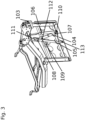
- the seat chassis includes a seat frame 100, a legrest chassis 101 and a legrest extension 102.
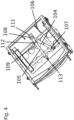
- a folding movement of the legrest chassis is shown. If the figures are viewed in reverse order, the legrest chassis folds out.
- the legrest chassis 101 can be pivoted about a geometric pivot axis.
- the pivot axis is defined by the pivot element 103 .
- the pivoting movement of the legrest chassis 101 is triggered by the seat frame 100 being moved forwards, ie towards the legrests chassis 101, or backwards, ie away from the legrests chassis 101.
- the legrest chassis 101 is folded.
- the legrest chassis 101 is unfolded.
- the seat chassis includes a first strut 104 , a second strut 105 and a third strut 106 .
- the second strut 105 is connected to the seat frame 100 via the third strut 106 .
- the first strut 104 can be rotated about a first pivot point 107 and also has a first elongated hole 109 , a first guide element 108 and a cantilever 110 .
- the third strut 106 is connected to the boom 110 .
- the second strut 105 can be rotated about a second pivot point 113 and has a second elongated hole 111 and a second guide element 112 .
- the second slot 111 is open on one side. This has the advantage that when assembling the seat furniture chassis, the first guide element 108 can be inserted into the elongated hole without any further effort.
- the third strut 106 is pushed forward due to its attachment to the seat frame 100, so that it exerts a force on the bracket 110 to which it is connected. This force triggers a pivoting of the first strut 104 about the first pivot point 107 . Due to the arrangement of the second guide element 112 in the first slot 109, the Due to the curved shape of the slot 109 and the arrangement of the first guide element 108 in the second slot 111, the second strut 105 is pivoted about the second pivot point 113 and pulled in the direction of the legrest chassis 101.
- legrest extension 102 is fully retracted. This is particularly advantageous in this position since the legrest chassis 101 is at the position with the smallest distance between the seat frame 100 and the floor surface on which the chair chassis is standing. In order to create a comparatively long support surface for a user's legs with a comparatively small installation space, it is advantageous for the leg support extension 102 to be completely retracted in this position.
- the legrest extension 102 is slightly extended again to tighten a fabric with which the legrest extension 102 and the legrest chassis 101 may be covered. This reduces the risk of unwanted creases in the fabric when the legrest chassis 101 is folded. This is achieved by moving the end of the third strut 106, which is connected to the seat frame 100, in a horizontal direction over the pivot axis of the legrest chassis. After this movement, the third strut 106 pulls on the arm 110 as the legrest chassis 101 folds in further, so that the legrest extension 102 is extended.
Landscapes
- Health & Medical Sciences (AREA)
- Dentistry (AREA)
- General Health & Medical Sciences (AREA)
- Passenger Equipment (AREA)
- Seats For Vehicles (AREA)
- Legs For Furniture In General (AREA)
- Mattresses And Other Support Structures For Chairs And Beds (AREA)
- Chair Legs, Seat Parts, And Backrests (AREA)
- Chairs For Special Purposes, Such As Reclining Chairs (AREA)
Claims (15)
- Châssis de siège comprenant un cadre d'assise (100), un châssis de repose-jambe (101) agencé de manière pivotante sur celui-ci et une rallonge de repose-jambe (102) rentrable et sortable, dans lequel la rallonge de repose-jambe (102) est agencée au niveau du châssis de repose-jambe (101), dans lequel le châssis de repose-jambe (101) est pivotant d'une position dépliée dans une position repliée, dans lequel la rallonge de repose-jambe (102) est reliée par le biais d'une première traverse (104) et d'une deuxième traverse (105) au châssis de repose-jambe (101), dans lequel la première traverse (104) présente un premier élément de guidage (108), et dans lequel la deuxième traverse (105) présente un second trou oblong (111) et un second élément de guidage (112), dans lequel le premier élément de guidage (108) est agencé de manière mobile dans le second trou oblong (111), caractérisé en ce que la première traverse (104) présente un premier trou oblong (109) et que le second élément de guidage (112) est agencé de manière mobile dans le premier trou oblong (109).
- Châssis de siège selon la revendication 1, caractérisé en ce que le premier élément de guidage (108) et le second élément de guidage (112) comportent respectivement un roulement à billes.
- Châssis de siège selon l'une quelconque des revendications précédentes, caractérisé en ce que le premier trou oblong (109) présente une forme pliée.
- Châssis de siège selon l'une quelconque des revendications précédentes, caractérisé en ce que la première traverse (104) présente un corps de base, dans lequel le premier trou oblong (109) s'étend dans un angle supérieur à 45° à partir du corps de base.
- Châssis de siège selon l'une quelconque des revendications précédentes, caractérisé en ce que le second trou oblong (111) présente une extrémité ouverte.
- Châssis de siège selon l'une quelconque des revendications précédentes, caractérisé en ce que la première traverse (104) est pivotante par rapport au châssis de repose-jambe (101) et à la deuxième traverse (105).
- Châssis de siège selon l'une quelconque des revendications précédentes, caractérisé en ce que la deuxième traverse (105) est pivotante par rapport à la première traverse (104) et à la rallonge de repose-jambe (102).
- Châssis de siège selon l'une quelconque des revendications précédentes, caractérisé en ce que la première traverse (104) est pivotante autour d'un premier point de rotation (107), dans lequel la première traverse (104) est fixée au premier point de rotation (107) au châssis de repose-jambe (101).
- Châssis de siège selon la revendication précédente, caractérisé en ce que le premier point de rotation (107) est agencé de manière fixe par rapport au châssis de repose-jambe (101).
- Châssis de siège selon l'une quelconque des revendications précédentes, caractérisé en ce que la deuxième traverse (105) est pivotante autour d'un second point de rotation (113), dans lequel la deuxième traverse (105) est fixée au second point de rotation (113) à la rallonge de repose-jambe (102).
- Châssis de siège selon l'une quelconque des revendications précédentes, caractérisé en ce que lors d'un pivotement de la première traverse (105) autour du premier point de rotation (107), le premier élément de guidage (108) et le second élément de guidage (112) sont déplacés dans le premier trou oblong (109) ou le second trou oblong (111).
- Châssis de siège selon l'une quelconque des revendications précédentes, caractérisé en ce que le second élément de guidage (112) est agencé entre le second trou oblong (111) et le second point de rotation (113).
- Châssis de siège selon l'une quelconque des revendications précédentes, caractérisé en ce que le châssis de siège comporte une troisième traverse (106), dans lequel la troisième traverse (106) est agencée à une première extrémité de manière pivotante sur le cadre d'assise (100), et dans lequel la troisième traverse (106) est reliée à une seconde extrémité à une flèche (110) agencée au niveau de la première traverse (104), et dans lequel la troisième traverse (106) dévie la première traverse (104) lors du repliage du châssis de repose-jambe (101).
- Châssis de siège selon l'une quelconque des revendications précédentes, caractérisé en ce que le châssis de repose-jambe (101) est pivotant autour d'un axe de rotation géométrique, dans lequel la première extrémité de la troisième traverse (106) est déplacée lors du processus de repliage du châssis de repose-jambe (101) dans une direction horizontale au-dessus de l'axe de rotation géométrique.
- Châssis de siège selon l'une quelconque des revendications précédentes, caractérisé en ce que la rallonge de repose-jambe (102) est rentrée à un moment pendant le processus de repliage du châssis de repose-jambe (101) plus que dans l'état replié du châssis de repose-jambe (101).
Applications Claiming Priority (2)
| Application Number | Priority Date | Filing Date | Title |
|---|---|---|---|
| DE202019104069.6U DE202019104069U1 (de) | 2019-07-23 | 2019-07-23 | Sitzmöbelchassis |
| PCT/EP2020/070702 WO2021013896A1 (fr) | 2019-07-23 | 2020-07-22 | Châssis de siège |
Publications (3)
| Publication Number | Publication Date |
|---|---|
| EP4003097A1 EP4003097A1 (fr) | 2022-06-01 |
| EP4003097C0 EP4003097C0 (fr) | 2023-06-28 |
| EP4003097B1 true EP4003097B1 (fr) | 2023-06-28 |
Family
ID=67701973
Family Applications (1)
| Application Number | Title | Priority Date | Filing Date |
|---|---|---|---|
| EP20750189.1A Active EP4003097B1 (fr) | 2019-07-23 | 2020-07-22 | Châssis de siège |
Country Status (7)
| Country | Link |
|---|---|
| US (1) | US11930937B2 (fr) |
| EP (1) | EP4003097B1 (fr) |
| CN (1) | CN113939215A (fr) |
| DE (1) | DE202019104069U1 (fr) |
| ES (1) | ES2953143T3 (fr) |
| PL (1) | PL4003097T3 (fr) |
| WO (1) | WO2021013896A1 (fr) |
Family Cites Families (8)
| Publication number | Priority date | Publication date | Assignee | Title |
|---|---|---|---|---|
| US3054640A (en) * | 1959-11-24 | 1962-09-18 | Lorenz Anton | Multiple position reclining chair |
| US5857739A (en) * | 1996-06-10 | 1999-01-12 | Nepsco, Inc. | Chair |
| DE202006014927U1 (de) * | 2006-09-28 | 2007-01-11 | Olsberg Hermann Everken Gmbh | Schwenkbare Stütze für ein Sitzmöbel |
| US8366188B2 (en) * | 2010-04-13 | 2013-02-05 | La-Z-Boy Incorporated | Release system for furniture member leg rest assemblies |
| KR101827419B1 (ko) * | 2016-10-17 | 2018-02-09 | 현대다이모스(주) | 뒤틀림 방지 기능을 갖는 레그레스트 |
| US10849432B2 (en) * | 2018-11-14 | 2020-12-01 | Gary Michael Pritchard | Methods and apparatus for variable user position seating |
| DE202019101920U1 (de) * | 2019-04-03 | 2020-07-06 | Innotec Motion GmbH | Sitzmöbelchassis |
| US20230200534A1 (en) * | 2021-12-28 | 2023-06-29 | Dongguan Weihong Smart Home Technology Co., Ltd. | Folding chair device |
-
2019
- 2019-07-23 DE DE202019104069.6U patent/DE202019104069U1/de active Active
-
2020
- 2020-07-22 WO PCT/EP2020/070702 patent/WO2021013896A1/fr unknown
- 2020-07-22 PL PL20750189.1T patent/PL4003097T3/pl unknown
- 2020-07-22 CN CN202080041515.XA patent/CN113939215A/zh active Pending
- 2020-07-22 ES ES20750189T patent/ES2953143T3/es active Active
- 2020-07-22 EP EP20750189.1A patent/EP4003097B1/fr active Active
-
2021
- 2021-11-11 US US17/524,246 patent/US11930937B2/en active Active
Also Published As
| Publication number | Publication date |
|---|---|
| EP4003097C0 (fr) | 2023-06-28 |
| ES2953143T3 (es) | 2023-11-08 |
| CN113939215A (zh) | 2022-01-14 |
| US11930937B2 (en) | 2024-03-19 |
| DE202019104069U1 (de) | 2019-08-02 |
| PL4003097T3 (pl) | 2023-10-23 |
| EP4003097A1 (fr) | 2022-06-01 |
| US20220061533A1 (en) | 2022-03-03 |
| WO2021013896A1 (fr) | 2021-01-28 |
Similar Documents
| Publication | Publication Date | Title |
|---|---|---|
| DE60110488T2 (de) | Ausziehfussstütze, insbesondere für Sessel, Sofas und dergleichen | |
| EP3965616B1 (fr) | Meuble d'assise comprenant une fonction d'écartement constant du mur et un élément de pied basculant | |
| DE202015102093U1 (de) | Sessel | |
| EP3426094B1 (fr) | Châssis de siège comportant un repose-pieds rétractable et déployable | |
| EP2356922B1 (fr) | Châssis de meuble pour s'asseoir/s'allonger | |
| EP2996516A1 (fr) | Dispositif extensible et escamotable pour repose-pied et/ou un repose-jambe d'un meuble destiné à s'assoir et/ou à s'allonger | |
| EP3965617B1 (fr) | Siège comprenant une fonction wallaway à double moteur | |
| DE102013104760B3 (de) | Fahrzeugsitz, insbesondere für ein Kraftfahrzeug | |
| DE202013105793U1 (de) | Sitzmöbel | |
| DE112008002844B4 (de) | Aufhängungsmechanismus mit integriertem Verkippungsmechanismus | |
| EP3228220B1 (fr) | Couchette/siège | |
| EP2638827A1 (fr) | Armature pivotante pour le réglage d'un meuble rembourré | |
| EP4003097B1 (fr) | Châssis de siège | |
| DE2601691C3 (de) | Hebelverstellgetriebe für Sitz-Liegesessel | |
| EP3426095B1 (fr) | Système comprenant un châssis de repose-pied et un châssis de meuble d'assise | |
| EP2907412A1 (fr) | Siège doté de repose-pieds pivotants | |
| DE1404660B2 (de) | Verstellsessel | |
| EP1754426B1 (fr) | Siège avec repose-jambes extractable | |
| DE202012100960U1 (de) | Sitz-/Liegemöbel | |
| WO2020200927A1 (fr) | Châssis de meuble d'assise | |
| DE102011109668A1 (de) | Sitzmöbel mit verstellbarer Kopfstütze | |
| DE202018100112U1 (de) | Chassis für ein Sitz- und/oder Liegemöbel | |
| DE3127310C2 (fr) | ||
| DE202016104974U1 (de) | Sitzmöbel mit ausschwenkbarer Fußstütze | |
| DE102016116894A1 (de) | Sitzmöbel mit ausschwenkbarer Fußstütze |
Legal Events
| Date | Code | Title | Description |
|---|---|---|---|
| STAA | Information on the status of an ep patent application or granted ep patent |
Free format text: STATUS: UNKNOWN |
|
| STAA | Information on the status of an ep patent application or granted ep patent |
Free format text: STATUS: THE INTERNATIONAL PUBLICATION HAS BEEN MADE |
|
| PUAI | Public reference made under article 153(3) epc to a published international application that has entered the european phase |
Free format text: ORIGINAL CODE: 0009012 |
|
| STAA | Information on the status of an ep patent application or granted ep patent |
Free format text: STATUS: REQUEST FOR EXAMINATION WAS MADE |
|
| 17P | Request for examination filed |
Effective date: 20220223 |
|
| AK | Designated contracting states |
Kind code of ref document: A1 Designated state(s): AL AT BE BG CH CY CZ DE DK EE ES FI FR GB GR HR HU IE IS IT LI LT LU LV MC MK MT NL NO PL PT RO RS SE SI SK SM TR |
|
| DAV | Request for validation of the european patent (deleted) | ||
| DAX | Request for extension of the european patent (deleted) | ||
| GRAP | Despatch of communication of intention to grant a patent |
Free format text: ORIGINAL CODE: EPIDOSNIGR1 |
|
| STAA | Information on the status of an ep patent application or granted ep patent |
Free format text: STATUS: GRANT OF PATENT IS INTENDED |
|
| INTG | Intention to grant announced |
Effective date: 20230112 |
|
| GRAS | Grant fee paid |
Free format text: ORIGINAL CODE: EPIDOSNIGR3 |
|
| GRAA | (expected) grant |
Free format text: ORIGINAL CODE: 0009210 |
|
| STAA | Information on the status of an ep patent application or granted ep patent |
Free format text: STATUS: THE PATENT HAS BEEN GRANTED |
|
| AK | Designated contracting states |
Kind code of ref document: B1 Designated state(s): AL AT BE BG CH CY CZ DE DK EE ES FI FR GB GR HR HU IE IS IT LI LT LU LV MC MK MT NL NO PL PT RO RS SE SI SK SM TR |
|
| REG | Reference to a national code |
Ref country code: CH Ref legal event code: EP |
|
| REG | Reference to a national code |
Ref country code: AT Ref legal event code: REF Ref document number: 1581933 Country of ref document: AT Kind code of ref document: T Effective date: 20230715 |
|
| REG | Reference to a national code |
Ref country code: IE Ref legal event code: FG4D Free format text: LANGUAGE OF EP DOCUMENT: GERMAN |
|
| REG | Reference to a national code |
Ref country code: DE Ref legal event code: R096 Ref document number: 502020003975 Country of ref document: DE |
|
| U01 | Request for unitary effect filed |
Effective date: 20230711 |
|
| U07 | Unitary effect registered |
Designated state(s): AT BE BG DE DK EE FI FR IT LT LU LV MT NL PT SE SI Effective date: 20230721 |
|
| REG | Reference to a national code |
Ref country code: NO Ref legal event code: T2 Effective date: 20230628 |
|
| REG | Reference to a national code |
Ref country code: LT Ref legal event code: MG9D |
|
| PGFP | Annual fee paid to national office [announced via postgrant information from national office to epo] |
Ref country code: TR Payment date: 20230915 Year of fee payment: 4 Ref country code: NO Payment date: 20230721 Year of fee payment: 4 Ref country code: ES Payment date: 20230927 Year of fee payment: 4 |
|
| REG | Reference to a national code |
Ref country code: ES Ref legal event code: FG2A Ref document number: 2953143 Country of ref document: ES Kind code of ref document: T3 Effective date: 20231108 |
|
| PG25 | Lapsed in a contracting state [announced via postgrant information from national office to epo] |
Ref country code: RS Free format text: LAPSE BECAUSE OF FAILURE TO SUBMIT A TRANSLATION OF THE DESCRIPTION OR TO PAY THE FEE WITHIN THE PRESCRIBED TIME-LIMIT Effective date: 20230628 Ref country code: HR Free format text: LAPSE BECAUSE OF FAILURE TO SUBMIT A TRANSLATION OF THE DESCRIPTION OR TO PAY THE FEE WITHIN THE PRESCRIBED TIME-LIMIT Effective date: 20230628 Ref country code: GR Free format text: LAPSE BECAUSE OF FAILURE TO SUBMIT A TRANSLATION OF THE DESCRIPTION OR TO PAY THE FEE WITHIN THE PRESCRIBED TIME-LIMIT Effective date: 20230929 |
|
| U20 | Renewal fee paid [unitary effect] |
Year of fee payment: 4 Effective date: 20231031 |
|
| PG25 | Lapsed in a contracting state [announced via postgrant information from national office to epo] |
Ref country code: SK Free format text: LAPSE BECAUSE OF FAILURE TO SUBMIT A TRANSLATION OF THE DESCRIPTION OR TO PAY THE FEE WITHIN THE PRESCRIBED TIME-LIMIT Effective date: 20230628 |
|
| PG25 | Lapsed in a contracting state [announced via postgrant information from national office to epo] |
Ref country code: IS Free format text: LAPSE BECAUSE OF FAILURE TO SUBMIT A TRANSLATION OF THE DESCRIPTION OR TO PAY THE FEE WITHIN THE PRESCRIBED TIME-LIMIT Effective date: 20231028 |
|
| PG25 | Lapsed in a contracting state [announced via postgrant information from national office to epo] |
Ref country code: SM Free format text: LAPSE BECAUSE OF FAILURE TO SUBMIT A TRANSLATION OF THE DESCRIPTION OR TO PAY THE FEE WITHIN THE PRESCRIBED TIME-LIMIT Effective date: 20230628 Ref country code: SK Free format text: LAPSE BECAUSE OF FAILURE TO SUBMIT A TRANSLATION OF THE DESCRIPTION OR TO PAY THE FEE WITHIN THE PRESCRIBED TIME-LIMIT Effective date: 20230628 Ref country code: RO Free format text: LAPSE BECAUSE OF FAILURE TO SUBMIT A TRANSLATION OF THE DESCRIPTION OR TO PAY THE FEE WITHIN THE PRESCRIBED TIME-LIMIT Effective date: 20230628 Ref country code: IS Free format text: LAPSE BECAUSE OF FAILURE TO SUBMIT A TRANSLATION OF THE DESCRIPTION OR TO PAY THE FEE WITHIN THE PRESCRIBED TIME-LIMIT Effective date: 20231028 Ref country code: CZ Free format text: LAPSE BECAUSE OF FAILURE TO SUBMIT A TRANSLATION OF THE DESCRIPTION OR TO PAY THE FEE WITHIN THE PRESCRIBED TIME-LIMIT Effective date: 20230628 |
|
| PGFP | Annual fee paid to national office [announced via postgrant information from national office to epo] |
Ref country code: PL Payment date: 20230818 Year of fee payment: 4 |
|
| REG | Reference to a national code |
Ref country code: CH Ref legal event code: PL |
|
| PG25 | Lapsed in a contracting state [announced via postgrant information from national office to epo] |
Ref country code: MC Free format text: LAPSE BECAUSE OF FAILURE TO SUBMIT A TRANSLATION OF THE DESCRIPTION OR TO PAY THE FEE WITHIN THE PRESCRIBED TIME-LIMIT Effective date: 20230628 |
|
| PG25 | Lapsed in a contracting state [announced via postgrant information from national office to epo] |
Ref country code: MC Free format text: LAPSE BECAUSE OF FAILURE TO SUBMIT A TRANSLATION OF THE DESCRIPTION OR TO PAY THE FEE WITHIN THE PRESCRIBED TIME-LIMIT Effective date: 20230628 |
|
| REG | Reference to a national code |
Ref country code: DE Ref legal event code: R097 Ref document number: 502020003975 Country of ref document: DE |
|
| REG | Reference to a national code |
Ref country code: IE Ref legal event code: MM4A |
|
| PG25 | Lapsed in a contracting state [announced via postgrant information from national office to epo] |
Ref country code: CH Free format text: LAPSE BECAUSE OF NON-PAYMENT OF DUE FEES Effective date: 20230731 |
|
| PLBE | No opposition filed within time limit |
Free format text: ORIGINAL CODE: 0009261 |
|
| STAA | Information on the status of an ep patent application or granted ep patent |
Free format text: STATUS: NO OPPOSITION FILED WITHIN TIME LIMIT |