EP4002974A2 - Vorrichtung zur verbesserung des luftstrommanagements und der kühlung in hybridgekühlter elektronik - Google Patents
Vorrichtung zur verbesserung des luftstrommanagements und der kühlung in hybridgekühlter elektronik Download PDFInfo
- Publication number
- EP4002974A2 EP4002974A2 EP22151379.9A EP22151379A EP4002974A2 EP 4002974 A2 EP4002974 A2 EP 4002974A2 EP 22151379 A EP22151379 A EP 22151379A EP 4002974 A2 EP4002974 A2 EP 4002974A2
- Authority
- EP
- European Patent Office
- Prior art keywords
- baffle
- edge
- coupled
- blade
- unit
- Prior art date
- Legal status (The legal status is an assumption and is not a legal conclusion. Google has not performed a legal analysis and makes no representation as to the accuracy of the status listed.)
- Granted
Links
Images


Classifications
-
- H—ELECTRICITY
- H05—ELECTRIC TECHNIQUES NOT OTHERWISE PROVIDED FOR
- H05K—PRINTED CIRCUITS; CASINGS OR CONSTRUCTIONAL DETAILS OF ELECTRIC APPARATUS; MANUFACTURE OF ASSEMBLAGES OF ELECTRICAL COMPONENTS
- H05K7/00—Constructional details common to different types of electric apparatus
- H05K7/20—Modifications to facilitate cooling, ventilating, or heating
- H05K7/2039—Modifications to facilitate cooling, ventilating, or heating characterised by the heat transfer by conduction from the heat generating element to a dissipating body
-
- H—ELECTRICITY
- H05—ELECTRIC TECHNIQUES NOT OTHERWISE PROVIDED FOR
- H05K—PRINTED CIRCUITS; CASINGS OR CONSTRUCTIONAL DETAILS OF ELECTRIC APPARATUS; MANUFACTURE OF ASSEMBLAGES OF ELECTRICAL COMPONENTS
- H05K7/00—Constructional details common to different types of electric apparatus
- H05K7/20—Modifications to facilitate cooling, ventilating, or heating
- H05K7/20009—Modifications to facilitate cooling, ventilating, or heating using a gaseous coolant in electronic enclosures
- H05K7/20136—Forced ventilation, e.g. by fans
- H05K7/20145—Means for directing air flow, e.g. ducts, deflectors, plenum or guides
-
- H—ELECTRICITY
- H05—ELECTRIC TECHNIQUES NOT OTHERWISE PROVIDED FOR
- H05K—PRINTED CIRCUITS; CASINGS OR CONSTRUCTIONAL DETAILS OF ELECTRIC APPARATUS; MANUFACTURE OF ASSEMBLAGES OF ELECTRICAL COMPONENTS
- H05K7/00—Constructional details common to different types of electric apparatus
- H05K7/20—Modifications to facilitate cooling, ventilating, or heating
- H05K7/20218—Modifications to facilitate cooling, ventilating, or heating using a liquid coolant without phase change in electronic enclosures
-
- H—ELECTRICITY
- H05—ELECTRIC TECHNIQUES NOT OTHERWISE PROVIDED FOR
- H05K—PRINTED CIRCUITS; CASINGS OR CONSTRUCTIONAL DETAILS OF ELECTRIC APPARATUS; MANUFACTURE OF ASSEMBLAGES OF ELECTRICAL COMPONENTS
- H05K7/00—Constructional details common to different types of electric apparatus
- H05K7/20—Modifications to facilitate cooling, ventilating, or heating
- H05K7/20218—Modifications to facilitate cooling, ventilating, or heating using a liquid coolant without phase change in electronic enclosures
- H05K7/20254—Cold plates transferring heat from heat source to coolant
-
- H—ELECTRICITY
- H05—ELECTRIC TECHNIQUES NOT OTHERWISE PROVIDED FOR
- H05K—PRINTED CIRCUITS; CASINGS OR CONSTRUCTIONAL DETAILS OF ELECTRIC APPARATUS; MANUFACTURE OF ASSEMBLAGES OF ELECTRICAL COMPONENTS
- H05K7/00—Constructional details common to different types of electric apparatus
- H05K7/20—Modifications to facilitate cooling, ventilating, or heating
- H05K7/20709—Modifications to facilitate cooling, ventilating, or heating for server racks or cabinets; for data centers, e.g. 19-inch computer racks
- H05K7/20718—Forced ventilation of a gaseous coolant
- H05K7/20727—Forced ventilation of a gaseous coolant within server blades for removing heat from heat source
-
- H—ELECTRICITY
- H05—ELECTRIC TECHNIQUES NOT OTHERWISE PROVIDED FOR
- H05K—PRINTED CIRCUITS; CASINGS OR CONSTRUCTIONAL DETAILS OF ELECTRIC APPARATUS; MANUFACTURE OF ASSEMBLAGES OF ELECTRICAL COMPONENTS
- H05K7/00—Constructional details common to different types of electric apparatus
- H05K7/20—Modifications to facilitate cooling, ventilating, or heating
- H05K7/20709—Modifications to facilitate cooling, ventilating, or heating for server racks or cabinets; for data centers, e.g. 19-inch computer racks
- H05K7/20763—Liquid cooling without phase change
- H05K7/20772—Liquid cooling without phase change within server blades for removing heat from heat source
Definitions
- the disclosed embodiments relate generally to hybrid cooling systems for temperature control of electronic equipment and in particular, but not exclusively, to a device for improving liquid cooling by managing airflow in hybrid-cooled electronics.
- IT equipment such as servers, blade servers, routers, edge servers, etc.
- Much modern information technology (IT) equipment such as servers, blade servers, routers, edge servers, etc.
- the heat generated by individual components-especially high-power components such as processors and SoC which includes multiple chiplets-makes many of these individual components impossible or difficult to cool effectively with air cooling systems.
- Modern IT equipment therefore requires liquid cooling or liquid-air hybrid cooling-i.e., cooling with a combination of air cooling and liquid cooling.
- some pieces of IT equipment have an on-board liquid cooling system that is thermally coupled, using elements such as cold plates, to individual components that need cooling.
- These designs improve the thermal capability by locating the cooling liquid closer to the heat source.
- these on-board liquid cooling systems usually do not operate in isolation. They are usually coupled to at least one larger cooling system, such as liquid cooling system in an electronics rack, and the rack's cooling system can further be coupled to the liquid cooling system of a larger facility such as a data center. In such a system, the data center's cooling system circulates a working fluid through the rack cooling system, which in turn circulates the working fluid through the cooling system on the piece of IT equipment.
- the present disclosure intends to solve at least one of the technical problems in the related art.
- Embodiments of an aspect of the present disclosure provide a baffle unit, including: an elastic member; and one or more baffle blades, each baffle blade having a first edge and a second edge, wherein each baffle blade has its first edge coupled to the elastic member, wherein each baffle blade rotates about and deforms the elastic member in response to aerodynamic forces applied to the one or more baffle blades.
- the baffle unit according to embodiments of the present disclosure is implemented to prevent or reduce thermal impact of the airflow on liquid cooling devices and enable airflow management optimization.
- the baffle unit further includes a shaft having a shaft axis and being centrally positioned in the elastic member, wherein each baffle blade has its first edge coupled to the shaft, so that each baffle blade is rotatable about the shaft axis in response to the aerodynamic forces.
- each baffle blade is quadrilateral and has a pair of long edges and a pair of short edges, and wherein one of the pair of long edges is the first edge and the other of the pair of long edges is the second edge.
- the baffle unit further includes an additional elastic member coupled to the second edge of one of the one or more baffle blades.
- the baffle unit further includes an additional baffle blade having a first edge and a second edge, wherein the first edge of the additional baffle blade is coupled to the additional elastic member.
- the second edge of one of the one or more baffle blades is fixed.
- Embodiments of another aspect of the present disclosure provide a baffle system, including: a mounting structure adapted to be mounted to a substrate; and a baffle unit according to any one of the above embodiments, the baffle unit being coupled to the mounting structure, wherein the second edge of one of the one or more baffle blades is fixed to the mounting structure.
- the mounting structure includes: a vertical support having a fixing channel therein; and an angled support having a fixing channel therein, wherein an end of the angled support is movably coupled to the fixing channel of the vertical support.
- the second edge of one of the one or more baffle blades is fixed to the fixing channel of the angled support.
- the end of the angled support that is movably coupled to the fixing channel of the vertical support can move within the fixing channel to change the angle of the angled support relative to the vertical support.
- Embodiments of another aspect of the present disclosure provide a hybrid cooling system, including: a substrate including one or more heat-generating electronic components mounted thereon; a liquid cooling system including cold plates coupled to at least one of the one or more heat-generating electronic components; an airflow source to direct airflow over the substrate; and one or more baffle units according to any one of the above embodiments, the one or more baffle units being coupled to the substrate, to one or more cold plates, or to both the substrate and to one or more cold plates.
- At least one of the one or more baffle units is coupled to a leading edge of the substrate.
- At least one of the one or more baffle units is coupled to a leading edge of at least one of the one or more cold plates.
- the one or more baffle units include multiple baffle units, each baffle unit coupled to the substrate upstream of each cold plate.
- At least one of the one or more baffle units is coupled to the substrate or to one or more cold plates by a mounting structure including: a vertical support having a fixing channel therein; and an angled support having a fixing channel therein, wherein an end of the angled support is movably coupled to the fixing channel of the vertical support.
- a mounting structure including: a vertical support having a fixing channel therein; and an angled support having a fixing channel therein, wherein an end of the angled support is movably coupled to the fixing channel of the vertical support.
- the second edge of one of the one or more baffle blades is fixed to the fixing channel of the angled support; and/or the end of the angled support that is movably coupled to the fixing channel of the vertical support can move within the fixing channel to change the angle of the angled support relative to the vertical support.
- Embodiments are described of a baffle unit for improving airflow management, and thus improving cooling, in a hybrid-cooled system. Specific details are described to provide an understanding of the embodiments, but one skilled in the relevant art will recognize that the invention can be practiced without one or more of the described details or with other methods, components, materials, etc. In some instances, well-known structures, materials, or operations are not shown or described in detail but are nonetheless encompassed within the scope of the invention.
- a device and approach are proposed to improve liquid cooling system performance, especially in hybrid cooling systems that cool with both air and liquid.
- the device includes mounting structures as well as baffle structures. Two major units are used for the baffle structure: a rotation unit and a blade.
- the rotation part is integrated with a flexible spring to control different opening ratios of the blade under different air pressures.
- This design ensures a proper and dynamically adjustable air flow resistance introduced to the air stream.
- the device is then mounted to the chassis and use as approach for blocking and directing the airflow away from the liquid cooling devices and, at the same time, assisting the airflow to the targeted heat loads.
- the device can be an independent unit from the liquid cooling devices, but it also can be designed as an integrated unit on the cooling device.
- the entire structural design enables flexible integration methods in different server chassis and board layout.
- the disclosed embodiments are used in liquid cooling system that use liquid cooling components such as cold plates that are directly attached to heat-generating electronics. Most uses of these solutions are in a hybrid cooling environment, which means that cooling air is still supplied for thermal management of devices that are air-cooled.
- the airflow can adversely impact the liquid cooling device through convection, especially forced convection, because some of the heat captured by the liquid can be extracted to the airflow before it is transferred to the external liquid heat transfer loop. This can impact the cooling performance on both the IT side and the facility side, and can also decrease the system efficiency.
- the liquid cooling devices can also introduce negative impact on the air cooling by functioning as airflow blockages, so that a separation of liquid cooled electronics and the electronics liquid cooling devices with the cooling air can also benefit the air cooling system.
- the disclosed embodiments also aim to improve the airflow management by minimizing the airflow resistance.
- the disclosed embodiments also aim to improve device availabilities and scalabilities, which means the design can be used for different types of systems and different uses. This not only decreases the cost associated with the hardware design, but also decreases the amount of system-level design needed to implement the device.
- the method can be used for designing and assembling different actual products for CPU, GPU and so on. With the increasing of the performance and the power packaged on a chip or processor, cooling is becoming critical to ensure a proper function and performance.
- the disclosed embodiments provide an advanced device that can be flexibly used for different scenarios, including different servers and airflow management requirements.
- the embodiments can be used in a system with multiple components and can be implemented on individual components.
- the embodiments enable flexible implementation and mounting methods in target locations, while enhancing airflow management by diverting the airflow instead of simply blocking the airflow.
- the airflow resistance introduced by the device is dynamically adjusted under the variation of the airflow speed.
- Figs. 1A-1B together illustrate an embodiment of a baffle unit 100.
- Fig. 1A is an exploded view
- Fig. 1B an assembled view.
- Baffle unit 100 includes a rotation unit 102 that is coupled to a pair of baffle blades 104 and 106.
- the illustrated embodiment includes two baffle blades, but other embodiments of baffle unit 100 can use a single baffle blade (see, e.g., Fig. 5 ).
- Rotation unit 102 includes an elastic member 108 positioned around a shaft 110.
- elastic member 108 can be a torsion spring, but other embodiments can use a different type of elastic member. Other embodiments can also omit shaft 110, so that rotation unit 102 includes only elastic member 108.
- Baffle blades 104 and 106 each include at least a first edge and a second edge: baffle blade 104 includes first edge 104a and second edge 104b, while baffle blade 106 includes first edge 106a and second edge 106b.
- baffle blades 104 and 106 can be quadrilateral (e.g., square or rectangular), but in other embodiments the baffle blades can have non-quadrilateral shapes. In still other embodiments baffle blades 104 and 106 need not have the same shape, quadrilateral or otherwise.
- the first edge and second edge of each baffle are the long edges of the rectangle.
- first edge 104a and first edge 106a can be rotatably coupled to shaft 110 so that each can rotate about the shaft and so that the relative angle between baffle blades 104 and 106 can change.
- first edge 104a first edge 106a can be coupled to elastic member 108 so that each baffle blade rotates about the center of the elastic member and the relative angle between baffle blades can change.
- each baffle blade-i.e., second edge 104b and second edge 106b- can be:
- second edge 104b and second edge 106b will be free; in one illustrated embodiment of baffle unit 100, second edge 104b is fixed and second edge 106b is free.
- elastic member 108 and/or shaft 110 can be fixed, so that the first edge of the attached baffle blade is also fixed and the second end is free.
- the second edge of one of the baffle blades 104 and 106 can also be coupled to an additional rotation unit 152 (see, e.g., Fig. 1C ).
- baffle unit 100 In operation of baffle unit 100, air flows from right to left, as shown by the arrow in the figure.
- the airflow source can be natural convection, but in other embodiments the airflow can be forced convection driven by an element such as a fan.
- the airflow can be forced convection driven by an element such as a fan.
- As air flows over the baffle unit it exerts an aerodynamic force on the baffle unit, more specifically on baffle blades 104 and 106.
- second edge 104b is fixed, second edge 106b is free, and rotation unit 102 is also free.
- the aerodynamic forces on baffle blades 104 and 106 causes elastic member 108 to deflect and exert a moment about the center of elastic member 108 and shaft 110 (if present).
- the term -Ks x is the elastic spring force component in a direction opposite the airflow and p d A represents the aerodynamic force in the airflow direction.
- K is the spring constant of elastic member 108
- s x is the deflection of elastic member 108 in the flow direction (this might be right, but it not commonly saying the deflection in certain direction)
- p d is the dynamic pressure of the airflow
- A is a reference area of the baffle blade
- ⁇ is the air density
- v is the airflow speed.
- baffle unit 100 shelters any components that are behind it (i.e., on the side of baffle unit opposite the origin of the airflow; see, e.g., Fig. 2B ) from exposure to the airflow.
- the baffle unit automatically adapts to a new equilibrium position where the above equation is satisfied.
- the baffle unit automatically adjusts according to the air pressure and, by selecting proper elasticity coefficient for elastic member 108, better airflow management efficiency can be achieved since the resistance is dynamically adjusted. This means the flow resistance is automatically and dynamically adjusted and optimized based on the airflow rates.
- Fig. 1C illustrates an embodiment of a baffle unit 150.
- baffle unit 100 shown in Figs. 1A-1B , can be extended by adding further rotation units and baffle blades; baffle unit 150 is such an extended embodiment of baffle unit 100.
- Baffle unit 150 includes all the elements of baffle unit 100, but also includes an additional rotation unit 152 coupled to the second edge of baffle blade 106 and also includes an additional baffle blade 154 whose first edge 154a is coupled to the additional rotation unit 152.
- rotation unit 152 includes an elastic member 156 positioned around a shaft 158.
- elastic member 156 is a torsion spring, but other embodiments can use a different type of elastic member.
- Other embodiments can also omit shaft 158, so that rotation unit 152 includes only elastic member 156.
- Additional baffle blade 154 includes at least a first edge 154a and a second edge 154b.
- baffle blade 154 can be quadrilateral (e.g., square or rectangular), but in other embodiments the baffle blade can have a non-quadrilateral shape, and in still other embodiments baffle blade 154 need not have the same shape as baffle blades 104 and 106.
- first edge 154a and second edge 154b can be the long edges of the rectangle.
- first edge 154a is coupled to elastic member 156 and, if present, to shaft 158, and second edge 154b is free.
- Baffle unit 150 operates similarly to baffle unit 100, except that restoring forces used by the baffle unit to counter aerodynamic forces are now provided by two rotation units instead of one.
- Figs. 2A-2B together illustrate an embodiment of a baffle system 200.
- Fig. 2A is a front view
- Fig. 2B is a side view.
- Baffle system 200 includes a baffle unit such as baffle unit 150 (see Fig. 1C ) and a mounting frame 202 used to secure baffle unit 150 to a component such as a substrate (see Figs. 3-7 ).
- Other embodiments of baffle system 200 can use different embodiments of a baffle unit, such as baffle unit 100 (see Figs. 1A-1B ).
- Mounting frame 202 includes a vertical support 204 and an angled support 206.
- Vertical support 204 includes a fixing channel 208 and angled support 206 includes a fixing channel 210.
- Other embodiments of mounting frame 202 can use more or less supports than shown, and in other embodiments the supports need not be in the illustrated position or have the illustrated relationship to each other.
- Fixing channels 208 and 210 allow baffle unit 150 to be coupled to the mounting frame, as well as allowing vertical support 204 to be coupled to angled support 206 in a way that the angled support can move relative to the vertical support, thus adjusting the position of baffle unit 150.
- second edge 104b of baffle blade 104 is movably fixed in fixing channel 210 using a fixing knob 214.
- an end of angled support 206 is movably fixed in fixing channel 208 using a fixing knob 212.
- This arrangement yields two ways to adjust the mounting frame and baffle unit 150.
- the angle of angled support 206 relative to vertical support 204, as well as the angle of baffle blade 104 relative to the airflow, can be adjusted by moving fixing knob 212, and thus the end of angled support 206, up and down within fixing channel 208.
- the angle of baffle blade 104 relative to the airflow, and thus the angle of baffle assembly 150 can additionally be adjusted by moving fixing knob 214 within fixing channel 210. This ensures a better airflow blocking and at the same time eliminates the impact on the airflow by minimizing the resistance introduced by the device.
- the fact that both the vertical and angled supports have fixing channels provides more implementation flexibility.
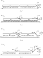
- Fig. 3 illustrates an embodiment of a hybrid cooling system 300 using an embodiment of a baffle system such as baffle system 200.
- a processor or other heat-generating electronic component 304 is mounted on a substrate 302.
- substrate 302 can be printed circuit board, but in other embodiments it can be another kind of substrate.
- a cold plate 306 is thermally coupled to component 304, so that heat is transferred from heat-generating component 304 into liquid flowing through the cold plate.
- other fluid components e.g., hoses, pumps, heat exchangers, valves, etc.
- Other heat-generating electronic components not shown in the figure can be air-cooled instead of liquid-cooled.
- Mounting frame 202 is coupled to substrate 302 by coupling by mounting at least vertical support 204 to substrate 302.
- Angled support 206 is coupled to fixing channel 208 as described above, and a two-blade baffle unit such as baffle unit 100 is coupled to the mounting frame, with the second end of baffle blade 104 coupled to the fixing channel 210 of angled support 206. Operation of the illustrated baffle system is as described above in connection with Figs. 1A-1C .
- Baffle system 200 is assembled on the right-hand side of the cold plate, which is the direction from which the incident airflow approaches the cold plate.
- the mounting location of the baffle system is next to the cold plate/cold plates, while the baffle blade is implemented form the airflow inlet. It is not highly dependent on the PCB or chassis/system layout or space/footprint availability. This shows that the extensible mounting frame can be mounted to different locations, thus eliminating dependency on the PCB or chassis layouts.
- the baffle blades form a blocking path for the airflow, and the air path is optimized to minimize its impact on the airflow. Fixing channels on the mounting frame enable adjustment between the two supports as well as between the rotating structure and one of the mounting frame (the inclined one as shown in Fig. 3 ). In an embodiment, there may be multiple angled supports 206 for more complex structural environment.
- Fig. 4 illustrates an embodiment of a hybrid cooling system 400 using an embodiment of a single-blade baffle unit.
- a pair of processors or other heat-generating electronic components 404a and 404b are mounted on a substrate 402.
- substrate 402 can be a printed circuit board, but in other embodiments it can be another kind of substrate.
- a cold plate 406 is thermally coupled to each component 404-cold plate 406a to component 404a, and cold plate 406b to component 404b-so that heat can be transferred from each heat-generating component 404 into liquid flowing through its corresponding cold plate 406.
- other fluid components e.g., hoses, pumps, heat exchangers, valves, etc.
- cold plates 406a and 406b are coupled to cold plates 406a and 406b to circulate cooling fluid through the cold plates.
- a single-blade baffle unit 408 is mounted on the leading edge of substrate 402 (i.e., the edge of the substrate closest to the source of incident airflow, or the edge on which the incident flow first impinges).
- Baffle unit 408 is a single-blade embodiment of baffle unit 100 (see Figs. 1A-1B ), with rotation structure 102 mounted on substrate 402 and baffle blade 106 extending from the rotation structure.
- baffle unit 408 can be mounted using the mounting frame 202 shown in Figs. 2A-2B , but in other embodiments baffle unit 408 can be mounted differently.
- baffle unit 408 can be implemented on another element such as a server chassis instead of on the printed circuit board 402 (see, e.g., Fig. 7 ).
- baffle unit 408 In operation, airflow over the system 400 encounters baffle unit 408 and exerts an aerodynamic force on baffle blade 106 that is balanced by the elastic member within rotation unit 102.
- the airflow source of the can be natural convection, but in other embodiments the airflow can be forced convection driven by an element such as a fan.
- baffle blade 106 diverts the airflow over one or both of cold plates 406b and 406a, reducing or preventing flow over the surfaces of the cold plates and thus reducing the extraction of heat from the cold plates that should stay within the liquid flowing through the cold plates for better cooling efficiency.
- Fig. 5 illustrates an embodiment of a hybrid cooling system 500 using an embodiment of a single-blade baffle unit.
- a pair of processors or other heat-generating electronic components 404a and 404b are mounted on a substrate 402.
- substrate 402 can be printed circuit board, but in other embodiments it can be some other kind of substrate.
- a cold plate 406 is thermally coupled to each component 404-cold plate 406a to component 404a, and cold plate 406b to component 404b-to transfer heat from each heat-generating component 404 into liquid flowing through its corresponding cold plate 406.
- other fluid components e.g., hoses, pumps, heat exchangers, valves, etc.
- cold plates 406a and 406b are coupled to cold plates 406a and 406b to circulate cooling fluid through the cold plates.
- hybrid cooling system 500 includes more baffle units and positions them differently, illustrating that the baffle units can be adjusted based on actual uses and that the design can be adapted to an existing system without modification of the existing system.
- variety of implementation methods can enable more flexible methods for applying the design according to different uses.
- a single-blade baffle unit 502a is mounted on the leading edge of cold plate 406a (i.e., the edge of the cold plate closest to the incident flow, or the edge of the cold plate on which the incident flow first impinges) and a single-blade baffle unit 502b is mounted on the leading edge of cold plate 406b.
- both baffle units 502a and 502b are single-blade embodiments of baffle unit 100 (see Figs. 1A-1B ), with rotation structure 102 mounted on cold plates 406a and 406b and corresponding baffle blades 106 extending from the rotation structure.
- baffle units 502a-502b can be mounted using the mounting frame 202 shown in Figs. 2A-2B , but in other embodiments baffle units 502a-502b can be mounted differently.
- baffle unit 502b In operation, airflow over system 500 encounters baffle unit 502b and exerts an aerodynamic force on baffle blade 106 that is balanced by the elastic member within rotation unit 102.
- the airflow source of the can be natural convection, but in other embodiments the airflow can be forced convection driven by an element such as a fan.
- Baffle units 502a and 502b thus prevent airflow over the surfaces of their respective cold plates, thus reducing or preventing convective extraction of heat from the cold plates that should stay within the liquid flowing through the cold plates for better cooling efficiency.
- Fig. 6 illustrates an embodiment of a hybrid cooling system 600 using embodiment of a single-blade baffle unit and an embodiment of a multi-blade baffle unit.
- a pair of processors or other heat-generating electronic components 404a and 404b are mounted on a substrate 402.
- substrate 402 can be printed circuit board, but in other embodiments it can be some other kind of substrate.
- a cold plate 406 is thermally coupled to each component 404-cold plate 406a to component 404a, and cold plate 406b to component 404b-to transfer heat from each heat-generating component 404 into liquid flowing through its corresponding cold plate 406.
- other fluid components e.g., hoses, pumps, heat exchangers, valves, etc.
- cold plates 406a and 406b are coupled to cold plates 406a and 406b to circulate cooling fluid through the cold plates.
- hybrid cooling system 600 uses different baffle units and positions them differently, illustrating one way the system can be adjusted based on actual use.
- the illustrated embodiment might require different types of mounting methods for achieving optimal airflow management, but this shows that the design can be implemented in an existing system without any need to modify the existing system.
- a multi-blade baffle unit 602a is mounted on substrate 402 ahead of cold plate 406a (i.e., the on the side of the cold plate closest to the origin of the incident airflow) and a single-blade baffle unit 602b is mounted on substrate 402 ahead of cold plate 406b.
- baffle unit 602a is an embodiment of baffle unit 100 that includes two rotational units 102a1 and 102a2 and two baffle blades 104 and 106.
- Rotational unit 102a1 is positioned on the surface of substrate 402 and coupled to the second edge of baffle blade 104.
- the first edge of baffle blade 104 and the first edge of baffle blade 106 are coupled to rotational unit 102a2.
- baffle units 602a-602b can be mounted using the mounting frame 202 shown in Figs. 2A-2B , but in other embodiments baffle units 602a-602b can be mounted differently.
- Baffle unit 602b is a single-blade embodiments of baffle unit 100 (see Figs. 1A-1B ), with rotation structure 102b positioned on substrate 402 and baffle blade 106 extending from the rotation structure.
- Other embodiments of system 600 need not use two baffle units, but can instead use only a single baffle unit positioned on substrate 402 (see, e.g., Fig. 3 ).
- Other embodiments also need not use single-blade baffle units but can instead use multi-blade baffle units as shown in Figs. 1A-1C .
- baffle unit 602b In operation, airflow over system 600 encounters baffle unit 602b and exerts an aerodynamic force on baffle blade 106.
- the aerodynamic force is balanced by the elastic member within rotation unit 102.
- the airflow source can be natural convection, but in other embodiments the airflow source can be forced convection driven by an element such as a fan.
- Baffle units 602a and 602b thus prevent airflow over the surfaces of their respective cold plates, and reduce or prevent convective extraction of heat that should remain in the liquid flowing through the cold plates for better cooling efficiency.
- Fig. 7 illustrates an embodiment of a hybrid cooling system 700 using an embodiment of a single-blade baffle unit.
- a pair of processors or other heat-generating electronic components 404a and 404b are mounted on a substrate 402.
- substrate 402 can be printed circuit board, but in other embodiments it can be some other kind of substrate.
- a cold plate 406 is thermally coupled to each component 404-cold plate 406a to component 404a, and cold plate 406b to component 404b-to transfer heat from each heat-generating component 404 into liquid flowing through its corresponding cold plate 406.
- other fluid components e.g., hoses, pumps, heat exchangers, valves, etc.
- cold plates 406a and 406b are coupled to cold plates 406a and 406b to circulate cooling fluid through the cold plates.
- hybrid cooling system 700 includes additional baffles beyond those mounted on cold plates 406a-406b. This may require different types of mounting methods. However, this further shows that the design can be implanted to an existing system without any modification requirement on the existing system.
- a single-blade baffle unit 502a is mounted on the leading edge of cold plate 406a (i.e., the edge of the cold plate closest to the incident flow, or the edge of the cold plate on which the incident flow first impinges) and a single-blade baffle unit 502b is mounted on the leading edge of cold plate 406b.
- baffle units 502a and 502b are single-blade embodiments of baffle unit 100 (see Figs. 1A-1B ), with rotation structure 102 mounted on cold plates 406a and 406b and baffle blade 106 extending from the rotation structure.
- Other embodiments need not use to baffle units, but instead can use only a single baffle unit, positioned on cold plate 406a or cold plate 406b.
- Other embodiments also need not use single-blade baffle units but can instead use multi-blade baffle units as shown in Figs. 1A-1C .
- system 700 includes one or more additional baffles 702 that can be mounted to a component 704 other than substrate 402 or cold plates 406a-406b.
- component 704 can be a cooling component 704, but other embodiments it can be a different type of component such as a server chassis or rack.
- baffle unit 702 can be mounted to component 704 using the mounting frame 202 shown in Figs. 2A-2B , but in other embodiments baffle unit 702 can be mounted differently.
- multi-devices implementations such as systems 700 and 500 can accommodate structural interference from liquid cooling loops. Comparing to the one shown in Fig. 2A , smaller devices can be implemented on individual cold plates.
- baffle unit 702 works together with baffle units 502a-502b, as described above for system 500, to limit or prevent convective heat transfer to the airflow from cold plates 406a-406b.
- baffle embodiments are possible besides the ones described above. For instance:
Landscapes
- Engineering & Computer Science (AREA)
- Microelectronics & Electronic Packaging (AREA)
- Physics & Mathematics (AREA)
- Thermal Sciences (AREA)
- Computer Hardware Design (AREA)
- General Engineering & Computer Science (AREA)
- Cooling Or The Like Of Electrical Apparatus (AREA)
- Motor Or Generator Cooling System (AREA)
Applications Claiming Priority (1)
| Application Number | Priority Date | Filing Date | Title |
|---|---|---|---|
| US17/148,063 US11523534B2 (en) | 2021-01-13 | 2021-01-13 | Device for airflow management and cooling improvement in hybrid-cooled electronics |
Publications (3)
| Publication Number | Publication Date |
|---|---|
| EP4002974A2 true EP4002974A2 (de) | 2022-05-25 |
| EP4002974A3 EP4002974A3 (de) | 2022-07-27 |
| EP4002974B1 EP4002974B1 (de) | 2023-08-30 |
Family
ID=79602296
Family Applications (1)
| Application Number | Title | Priority Date | Filing Date |
|---|---|---|---|
| EP22151379.9A Active EP4002974B1 (de) | 2021-01-13 | 2022-01-13 | Vorrichtung zur verbesserung des luftstrommanagements und der kühlung in hybridgekühlter elektronik |
Country Status (4)
| Country | Link |
|---|---|
| US (1) | US11523534B2 (de) |
| EP (1) | EP4002974B1 (de) |
| JP (1) | JP7277622B2 (de) |
| CN (1) | CN114765937B (de) |
Families Citing this family (1)
| Publication number | Priority date | Publication date | Assignee | Title |
|---|---|---|---|---|
| KR102628448B1 (ko) * | 2023-07-21 | 2024-01-23 | (주)익스프레스럭코리아 | 냉각효율이 향상된 전원공급장치 |
Family Cites Families (28)
| Publication number | Priority date | Publication date | Assignee | Title |
|---|---|---|---|---|
| US6011689A (en) * | 1998-04-27 | 2000-01-04 | Sun Microsystems, Inc. | Computer component cooling fan closure device and method thereof |
| US6330155B1 (en) * | 2000-03-28 | 2001-12-11 | Qtera Corporation | Method and apparatus for temperature control of electrical devices mounted on circuit boards |
| TW530994U (en) * | 2002-01-30 | 2003-05-01 | Foxconn Prec Components Co Ltd | Air conduction device of heat sink |
| TW535488B (en) * | 2002-05-29 | 2003-06-01 | Delta Electronics Inc | Flow direction control mechanism |
| US20070059176A1 (en) * | 2005-09-15 | 2007-03-15 | International Business Machines Corporation | Fluid moving device with low-drag impellers |
| LU91207B1 (fr) * | 2005-11-11 | 2007-05-14 | Uniflair Ind S P A | Système de refroidissement pour une pièce contenant de l'équipement électronique de traitement de données |
| US20070121295A1 (en) * | 2005-11-30 | 2007-05-31 | International Business Machines Corporation | Hybrid liquid-air cooled module |
| WO2008035579A1 (fr) | 2006-09-19 | 2008-03-27 | Nec Corporation | Appareil de refroidissement |
| US20100128431A1 (en) * | 2007-03-07 | 2010-05-27 | Andre Sloth Eriksen | Hybrid liquid-air cooled graphics display adapter |
| CN101568249A (zh) * | 2008-04-22 | 2009-10-28 | 鸿富锦精密工业(深圳)有限公司 | 电子系统及其风向限制装置 |
| TWI395095B (zh) | 2009-11-30 | 2013-05-01 | Ibm | 自調整散熱模組及其流量控制裝置 |
| US9038406B2 (en) * | 2010-05-26 | 2015-05-26 | International Business Machines Corporation | Dehumidifying cooling apparatus and method for an electronics rack |
| CN102566691B (zh) * | 2010-12-15 | 2016-08-10 | 国家电网公司 | 电子装置 |
| CN102902327A (zh) | 2011-07-28 | 2013-01-30 | 鸿富锦精密工业(深圳)有限公司 | 导风板 |
| US20130109290A1 (en) | 2011-10-27 | 2013-05-02 | Raytheon Company | Forced airflow control device and method of operation |
| TW201318538A (zh) * | 2011-10-31 | 2013-05-01 | Hon Hai Prec Ind Co Ltd | 擴展卡固定裝置及使用該擴展卡固定裝置的擴展卡模組 |
| JP2013185565A (ja) * | 2012-03-12 | 2013-09-19 | Panasonic Corp | 遠心ファン装置用ブレード、遠心ファン装置及びそれを備えた電子機器 |
| JP2015041668A (ja) * | 2013-08-21 | 2015-03-02 | 富士通株式会社 | 導風構造、基板及び電子装置 |
| US10624241B1 (en) | 2015-10-06 | 2020-04-14 | Amazon Technologies, Inc. | Rack mountable thermal regulation system |
| US9795055B1 (en) * | 2016-04-18 | 2017-10-17 | International Business Machines Corporation | Electronics cooling assembly with multi-position, airflow-blocking mechanism |
| US20180066663A1 (en) * | 2016-09-08 | 2018-03-08 | Intel Corporation | Cooling using coolant-driven fans |
| CN106502340B (zh) * | 2016-11-02 | 2019-06-28 | 英业达科技有限公司 | 服务器 |
| US20180376614A1 (en) * | 2017-06-23 | 2018-12-27 | Fortinet, Inc. | Check valve fan cover |
| US10631432B2 (en) * | 2018-03-05 | 2020-04-21 | Seagate Technology Llc | Dynamic air intake control assembly |
| US10736240B2 (en) * | 2018-05-24 | 2020-08-04 | Baidu Usa Llc | High reliability cooling module design for IT and data center liquid cooling |
| US11089713B2 (en) * | 2019-11-11 | 2021-08-10 | Dell Products L.P. | Systems and methods for redirection of airflow in an information handling system after an air mover fault |
| TWM597825U (zh) | 2020-04-08 | 2020-07-01 | 立端科技股份有限公司 | 具防止回流功能的散熱風扇模組以及包含該散熱風扇模組的主機系統 |
| CN212274195U (zh) * | 2020-06-03 | 2021-01-01 | 广州驰领医疗器械有限责任公司 | 一种医疗器械车间换气装置 |
-
2021
- 2021-01-13 US US17/148,063 patent/US11523534B2/en active Active
- 2021-12-29 CN CN202111639492.5A patent/CN114765937B/zh active Active
-
2022
- 2022-01-12 JP JP2022003281A patent/JP7277622B2/ja active Active
- 2022-01-13 EP EP22151379.9A patent/EP4002974B1/de active Active
Also Published As
| Publication number | Publication date |
|---|---|
| EP4002974B1 (de) | 2023-08-30 |
| US20220225531A1 (en) | 2022-07-14 |
| US11523534B2 (en) | 2022-12-06 |
| CN114765937B (zh) | 2025-07-11 |
| EP4002974A3 (de) | 2022-07-27 |
| JP7277622B2 (ja) | 2023-05-19 |
| CN114765937A (zh) | 2022-07-19 |
| JP2022050600A (ja) | 2022-03-30 |
Similar Documents
| Publication | Publication Date | Title |
|---|---|---|
| US6704199B2 (en) | Low profile equipment housing with angular fan | |
| US6512673B1 (en) | Low profile equipment housing with angular fan | |
| US6657860B2 (en) | Heat dissipating device and computer | |
| US7400501B2 (en) | Method and apparatus for acoustic noise reduction in a computer system having a vented cover | |
| US5871396A (en) | Convection type heat dissipation device for computers that is adjustable with respect to a heat source | |
| EP1675451B1 (de) | Flüssigkeitskühlmodul | |
| US7255532B2 (en) | Bi-directional blowers for cooling computers | |
| US9268377B2 (en) | Electronic device having a passive heat exchange device | |
| US7312992B2 (en) | Apparatus and method for transferring heat from processors | |
| US6282090B1 (en) | Apparatus for cooling central processing units in personal computers | |
| US7522413B2 (en) | Heat dissipating system | |
| US20060213643A1 (en) | Cooling apparatus and electronic equipment | |
| JP2003347778A (ja) | フロー制御機構 | |
| JP2005228216A (ja) | 電子機器 | |
| GB2403601A (en) | Heat sink with fins | |
| EP1669840B1 (de) | Batteriesystem für tragbaren Rechner | |
| EP4002974B1 (de) | Vorrichtung zur verbesserung des luftstrommanagements und der kühlung in hybridgekühlter elektronik | |
| TWI421025B (zh) | 散熱裝置 | |
| US8456829B2 (en) | All-in-one computer | |
| CN101340795B (zh) | 散热装置 | |
| WO2019015200A1 (zh) | 一种cpu挡风罩 | |
| CN117320340A (zh) | 遮阳板以及电子构件 | |
| CN101460036A (zh) | 散热装置 | |
| JP4682858B2 (ja) | 電子機器用の冷却装置 | |
| EP1918801B1 (de) | Elektronische integrierte Schaltvorrichtung mit verbessertem Kühlsystem |
Legal Events
| Date | Code | Title | Description |
|---|---|---|---|
| PUAI | Public reference made under article 153(3) epc to a published international application that has entered the european phase |
Free format text: ORIGINAL CODE: 0009012 |
|
| STAA | Information on the status of an ep patent application or granted ep patent |
Free format text: STATUS: THE APPLICATION HAS BEEN PUBLISHED |
|
| AK | Designated contracting states |
Kind code of ref document: A2 Designated state(s): AL AT BE BG CH CY CZ DE DK EE ES FI FR GB GR HR HU IE IS IT LI LT LU LV MC MK MT NL NO PL PT RO RS SE SI SK SM TR |
|
| PUAL | Search report despatched |
Free format text: ORIGINAL CODE: 0009013 |
|
| AK | Designated contracting states |
Kind code of ref document: A3 Designated state(s): AL AT BE BG CH CY CZ DE DK EE ES FI FR GB GR HR HU IE IS IT LI LT LU LV MC MK MT NL NO PL PT RO RS SE SI SK SM TR |
|
| RIC1 | Information provided on ipc code assigned before grant |
Ipc: H05K 7/20 20060101AFI20220620BHEP |
|
| STAA | Information on the status of an ep patent application or granted ep patent |
Free format text: STATUS: REQUEST FOR EXAMINATION WAS MADE |
|
| 17P | Request for examination filed |
Effective date: 20230127 |
|
| RBV | Designated contracting states (corrected) |
Designated state(s): AL AT BE BG CH CY CZ DE DK EE ES FI FR GB GR HR HU IE IS IT LI LT LU LV MC MK MT NL NO PL PT RO RS SE SI SK SM TR |
|
| GRAP | Despatch of communication of intention to grant a patent |
Free format text: ORIGINAL CODE: EPIDOSNIGR1 |
|
| STAA | Information on the status of an ep patent application or granted ep patent |
Free format text: STATUS: GRANT OF PATENT IS INTENDED |
|
| INTG | Intention to grant announced |
Effective date: 20230414 |
|
| GRAS | Grant fee paid |
Free format text: ORIGINAL CODE: EPIDOSNIGR3 |
|
| GRAA | (expected) grant |
Free format text: ORIGINAL CODE: 0009210 |
|
| STAA | Information on the status of an ep patent application or granted ep patent |
Free format text: STATUS: THE PATENT HAS BEEN GRANTED |
|
| AK | Designated contracting states |
Kind code of ref document: B1 Designated state(s): AL AT BE BG CH CY CZ DE DK EE ES FI FR GB GR HR HU IE IS IT LI LT LU LV MC MK MT NL NO PL PT RO RS SE SI SK SM TR |
|
| REG | Reference to a national code |
Ref country code: GB Ref legal event code: FG4D |
|
| REG | Reference to a national code |
Ref country code: CH Ref legal event code: EP |
|
| REG | Reference to a national code |
Ref country code: DE Ref legal event code: R096 Ref document number: 602022000387 Country of ref document: DE |
|
| REG | Reference to a national code |
Ref country code: IE Ref legal event code: FG4D |
|
| REG | Reference to a national code |
Ref country code: LT Ref legal event code: MG9D |
|
| REG | Reference to a national code |
Ref country code: NL Ref legal event code: MP Effective date: 20230830 |
|
| REG | Reference to a national code |
Ref country code: AT Ref legal event code: MK05 Ref document number: 1607172 Country of ref document: AT Kind code of ref document: T Effective date: 20230830 |
|
| PG25 | Lapsed in a contracting state [announced via postgrant information from national office to epo] |
Ref country code: GR Free format text: LAPSE BECAUSE OF FAILURE TO SUBMIT A TRANSLATION OF THE DESCRIPTION OR TO PAY THE FEE WITHIN THE PRESCRIBED TIME-LIMIT Effective date: 20231201 |
|
| PG25 | Lapsed in a contracting state [announced via postgrant information from national office to epo] |
Ref country code: IS Free format text: LAPSE BECAUSE OF FAILURE TO SUBMIT A TRANSLATION OF THE DESCRIPTION OR TO PAY THE FEE WITHIN THE PRESCRIBED TIME-LIMIT Effective date: 20231230 |
|
| PG25 | Lapsed in a contracting state [announced via postgrant information from national office to epo] |
Ref country code: SE Free format text: LAPSE BECAUSE OF FAILURE TO SUBMIT A TRANSLATION OF THE DESCRIPTION OR TO PAY THE FEE WITHIN THE PRESCRIBED TIME-LIMIT Effective date: 20230830 Ref country code: RS Free format text: LAPSE BECAUSE OF FAILURE TO SUBMIT A TRANSLATION OF THE DESCRIPTION OR TO PAY THE FEE WITHIN THE PRESCRIBED TIME-LIMIT Effective date: 20230830 Ref country code: NO Free format text: LAPSE BECAUSE OF FAILURE TO SUBMIT A TRANSLATION OF THE DESCRIPTION OR TO PAY THE FEE WITHIN THE PRESCRIBED TIME-LIMIT Effective date: 20231130 Ref country code: LV Free format text: LAPSE BECAUSE OF FAILURE TO SUBMIT A TRANSLATION OF THE DESCRIPTION OR TO PAY THE FEE WITHIN THE PRESCRIBED TIME-LIMIT Effective date: 20230830 Ref country code: LT Free format text: LAPSE BECAUSE OF FAILURE TO SUBMIT A TRANSLATION OF THE DESCRIPTION OR TO PAY THE FEE WITHIN THE PRESCRIBED TIME-LIMIT Effective date: 20230830 Ref country code: IS Free format text: LAPSE BECAUSE OF FAILURE TO SUBMIT A TRANSLATION OF THE DESCRIPTION OR TO PAY THE FEE WITHIN THE PRESCRIBED TIME-LIMIT Effective date: 20231230 Ref country code: HR Free format text: LAPSE BECAUSE OF FAILURE TO SUBMIT A TRANSLATION OF THE DESCRIPTION OR TO PAY THE FEE WITHIN THE PRESCRIBED TIME-LIMIT Effective date: 20230830 Ref country code: GR Free format text: LAPSE BECAUSE OF FAILURE TO SUBMIT A TRANSLATION OF THE DESCRIPTION OR TO PAY THE FEE WITHIN THE PRESCRIBED TIME-LIMIT Effective date: 20231201 Ref country code: FI Free format text: LAPSE BECAUSE OF FAILURE TO SUBMIT A TRANSLATION OF THE DESCRIPTION OR TO PAY THE FEE WITHIN THE PRESCRIBED TIME-LIMIT Effective date: 20230830 Ref country code: AT Free format text: LAPSE BECAUSE OF FAILURE TO SUBMIT A TRANSLATION OF THE DESCRIPTION OR TO PAY THE FEE WITHIN THE PRESCRIBED TIME-LIMIT Effective date: 20230830 |
|
| PG25 | Lapsed in a contracting state [announced via postgrant information from national office to epo] |
Ref country code: PL Free format text: LAPSE BECAUSE OF FAILURE TO SUBMIT A TRANSLATION OF THE DESCRIPTION OR TO PAY THE FEE WITHIN THE PRESCRIBED TIME-LIMIT Effective date: 20230830 Ref country code: NL Free format text: LAPSE BECAUSE OF FAILURE TO SUBMIT A TRANSLATION OF THE DESCRIPTION OR TO PAY THE FEE WITHIN THE PRESCRIBED TIME-LIMIT Effective date: 20230830 |
|
| PG25 | Lapsed in a contracting state [announced via postgrant information from national office to epo] |
Ref country code: ES Free format text: LAPSE BECAUSE OF FAILURE TO SUBMIT A TRANSLATION OF THE DESCRIPTION OR TO PAY THE FEE WITHIN THE PRESCRIBED TIME-LIMIT Effective date: 20230830 |
|
| PG25 | Lapsed in a contracting state [announced via postgrant information from national office to epo] |
Ref country code: SM Free format text: LAPSE BECAUSE OF FAILURE TO SUBMIT A TRANSLATION OF THE DESCRIPTION OR TO PAY THE FEE WITHIN THE PRESCRIBED TIME-LIMIT Effective date: 20230830 Ref country code: RO Free format text: LAPSE BECAUSE OF FAILURE TO SUBMIT A TRANSLATION OF THE DESCRIPTION OR TO PAY THE FEE WITHIN THE PRESCRIBED TIME-LIMIT Effective date: 20230830 Ref country code: ES Free format text: LAPSE BECAUSE OF FAILURE TO SUBMIT A TRANSLATION OF THE DESCRIPTION OR TO PAY THE FEE WITHIN THE PRESCRIBED TIME-LIMIT Effective date: 20230830 Ref country code: EE Free format text: LAPSE BECAUSE OF FAILURE TO SUBMIT A TRANSLATION OF THE DESCRIPTION OR TO PAY THE FEE WITHIN THE PRESCRIBED TIME-LIMIT Effective date: 20230830 Ref country code: DK Free format text: LAPSE BECAUSE OF FAILURE TO SUBMIT A TRANSLATION OF THE DESCRIPTION OR TO PAY THE FEE WITHIN THE PRESCRIBED TIME-LIMIT Effective date: 20230830 Ref country code: CZ Free format text: LAPSE BECAUSE OF FAILURE TO SUBMIT A TRANSLATION OF THE DESCRIPTION OR TO PAY THE FEE WITHIN THE PRESCRIBED TIME-LIMIT Effective date: 20230830 Ref country code: SK Free format text: LAPSE BECAUSE OF FAILURE TO SUBMIT A TRANSLATION OF THE DESCRIPTION OR TO PAY THE FEE WITHIN THE PRESCRIBED TIME-LIMIT Effective date: 20230830 Ref country code: PT Free format text: LAPSE BECAUSE OF FAILURE TO SUBMIT A TRANSLATION OF THE DESCRIPTION OR TO PAY THE FEE WITHIN THE PRESCRIBED TIME-LIMIT Effective date: 20240102 |
|
| PG25 | Lapsed in a contracting state [announced via postgrant information from national office to epo] |
Ref country code: IT Free format text: LAPSE BECAUSE OF FAILURE TO SUBMIT A TRANSLATION OF THE DESCRIPTION OR TO PAY THE FEE WITHIN THE PRESCRIBED TIME-LIMIT Effective date: 20230830 |
|
| REG | Reference to a national code |
Ref country code: DE Ref legal event code: R097 Ref document number: 602022000387 Country of ref document: DE |
|
| PLBE | No opposition filed within time limit |
Free format text: ORIGINAL CODE: 0009261 |
|
| STAA | Information on the status of an ep patent application or granted ep patent |
Free format text: STATUS: NO OPPOSITION FILED WITHIN TIME LIMIT |
|
| PG25 | Lapsed in a contracting state [announced via postgrant information from national office to epo] |
Ref country code: SI Free format text: LAPSE BECAUSE OF FAILURE TO SUBMIT A TRANSLATION OF THE DESCRIPTION OR TO PAY THE FEE WITHIN THE PRESCRIBED TIME-LIMIT Effective date: 20230830 |
|
| 26N | No opposition filed |
Effective date: 20240603 |
|
| PG25 | Lapsed in a contracting state [announced via postgrant information from national office to epo] |
Ref country code: MC Free format text: LAPSE BECAUSE OF FAILURE TO SUBMIT A TRANSLATION OF THE DESCRIPTION OR TO PAY THE FEE WITHIN THE PRESCRIBED TIME-LIMIT Effective date: 20230830 |
|
| PG25 | Lapsed in a contracting state [announced via postgrant information from national office to epo] |
Ref country code: MC Free format text: LAPSE BECAUSE OF FAILURE TO SUBMIT A TRANSLATION OF THE DESCRIPTION OR TO PAY THE FEE WITHIN THE PRESCRIBED TIME-LIMIT Effective date: 20230830 |
|
| PG25 | Lapsed in a contracting state [announced via postgrant information from national office to epo] |
Ref country code: LU Free format text: LAPSE BECAUSE OF NON-PAYMENT OF DUE FEES Effective date: 20240113 |
|
| PG25 | Lapsed in a contracting state [announced via postgrant information from national office to epo] |
Ref country code: LU Free format text: LAPSE BECAUSE OF NON-PAYMENT OF DUE FEES Effective date: 20240113 |
|
| PG25 | Lapsed in a contracting state [announced via postgrant information from national office to epo] |
Ref country code: BE Free format text: LAPSE BECAUSE OF NON-PAYMENT OF DUE FEES Effective date: 20240131 |
|
| PG25 | Lapsed in a contracting state [announced via postgrant information from national office to epo] |
Ref country code: BE Free format text: LAPSE BECAUSE OF NON-PAYMENT OF DUE FEES Effective date: 20240131 |
|
| REG | Reference to a national code |
Ref country code: BE Ref legal event code: MM Effective date: 20240131 |
|
| PG25 | Lapsed in a contracting state [announced via postgrant information from national office to epo] |
Ref country code: BG Free format text: LAPSE BECAUSE OF FAILURE TO SUBMIT A TRANSLATION OF THE DESCRIPTION OR TO PAY THE FEE WITHIN THE PRESCRIBED TIME-LIMIT Effective date: 20230830 |
|
| PG25 | Lapsed in a contracting state [announced via postgrant information from national office to epo] |
Ref country code: BG Free format text: LAPSE BECAUSE OF FAILURE TO SUBMIT A TRANSLATION OF THE DESCRIPTION OR TO PAY THE FEE WITHIN THE PRESCRIBED TIME-LIMIT Effective date: 20230830 |
|
| PG25 | Lapsed in a contracting state [announced via postgrant information from national office to epo] |
Ref country code: IE Free format text: LAPSE BECAUSE OF NON-PAYMENT OF DUE FEES Effective date: 20240113 |
|
| PG25 | Lapsed in a contracting state [announced via postgrant information from national office to epo] |
Ref country code: IE Free format text: LAPSE BECAUSE OF NON-PAYMENT OF DUE FEES Effective date: 20240113 |
|
| PG25 | Lapsed in a contracting state [announced via postgrant information from national office to epo] |
Ref country code: CY Free format text: LAPSE BECAUSE OF FAILURE TO SUBMIT A TRANSLATION OF THE DESCRIPTION OR TO PAY THE FEE WITHIN THE PRESCRIBED TIME-LIMIT; INVALID AB INITIO Effective date: 20220113 |
|
| REG | Reference to a national code |
Ref country code: CH Ref legal event code: PL |
|
| PG25 | Lapsed in a contracting state [announced via postgrant information from national office to epo] |
Ref country code: CH Free format text: LAPSE BECAUSE OF NON-PAYMENT OF DUE FEES Effective date: 20250131 |
|
| PG25 | Lapsed in a contracting state [announced via postgrant information from national office to epo] |
Ref country code: TR Free format text: LAPSE BECAUSE OF FAILURE TO SUBMIT A TRANSLATION OF THE DESCRIPTION OR TO PAY THE FEE WITHIN THE PRESCRIBED TIME-LIMIT Effective date: 20230830 |
|
| PGFP | Annual fee paid to national office [announced via postgrant information from national office to epo] |
Ref country code: FR Payment date: 20251208 Year of fee payment: 5 |
|
| PGFP | Annual fee paid to national office [announced via postgrant information from national office to epo] |
Ref country code: DE Payment date: 20260120 Year of fee payment: 5 |