EP4001705A1 - Parksperre, getriebe und antriebseinrichtung - Google Patents
Parksperre, getriebe und antriebseinrichtung Download PDFInfo
- Publication number
- EP4001705A1 EP4001705A1 EP21208332.3A EP21208332A EP4001705A1 EP 4001705 A1 EP4001705 A1 EP 4001705A1 EP 21208332 A EP21208332 A EP 21208332A EP 4001705 A1 EP4001705 A1 EP 4001705A1
- Authority
- EP
- European Patent Office
- Prior art keywords
- parking lock
- selector shaft
- cam
- shaft
- transmission
- Prior art date
- Legal status (The legal status is an assumption and is not a legal conclusion. Google has not performed a legal analysis and makes no representation as to the accuracy of the status listed.)
- Granted
Links
Images

Classifications
-
- F—MECHANICAL ENGINEERING; LIGHTING; HEATING; WEAPONS; BLASTING
- F16—ENGINEERING ELEMENTS AND UNITS; GENERAL MEASURES FOR PRODUCING AND MAINTAINING EFFECTIVE FUNCTIONING OF MACHINES OR INSTALLATIONS; THERMAL INSULATION IN GENERAL
- F16H—GEARING
- F16H63/00—Control outputs from the control unit to change-speed- or reversing-gearings for conveying rotary motion or to other devices than the final output mechanism
- F16H63/02—Final output mechanisms therefor; Actuating means for the final output mechanisms
- F16H63/30—Constructional features of the final output mechanisms
- F16H63/34—Locking or disabling mechanisms
- F16H63/3416—Parking lock mechanisms or brakes in the transmission
- F16H63/3425—Parking lock mechanisms or brakes in the transmission characterised by pawls or wheels
-
- F—MECHANICAL ENGINEERING; LIGHTING; HEATING; WEAPONS; BLASTING
- F16—ENGINEERING ELEMENTS AND UNITS; GENERAL MEASURES FOR PRODUCING AND MAINTAINING EFFECTIVE FUNCTIONING OF MACHINES OR INSTALLATIONS; THERMAL INSULATION IN GENERAL
- F16H—GEARING
- F16H63/00—Control outputs from the control unit to change-speed- or reversing-gearings for conveying rotary motion or to other devices than the final output mechanism
- F16H63/02—Final output mechanisms therefor; Actuating means for the final output mechanisms
- F16H63/30—Constructional features of the final output mechanisms
- F16H63/34—Locking or disabling mechanisms
- F16H63/3408—Locking or disabling mechanisms the locking mechanism being moved by the final actuating mechanism
-
- F—MECHANICAL ENGINEERING; LIGHTING; HEATING; WEAPONS; BLASTING
- F16—ENGINEERING ELEMENTS AND UNITS; GENERAL MEASURES FOR PRODUCING AND MAINTAINING EFFECTIVE FUNCTIONING OF MACHINES OR INSTALLATIONS; THERMAL INSULATION IN GENERAL
- F16H—GEARING
- F16H57/00—General details of gearing
- F16H57/02—Gearboxes; Mounting gearing therein
- F16H57/029—Gearboxes; Mounting gearing therein characterised by means for sealing the gearboxes, e.g. to improve airtightness
-
- F—MECHANICAL ENGINEERING; LIGHTING; HEATING; WEAPONS; BLASTING
- F16—ENGINEERING ELEMENTS AND UNITS; GENERAL MEASURES FOR PRODUCING AND MAINTAINING EFFECTIVE FUNCTIONING OF MACHINES OR INSTALLATIONS; THERMAL INSULATION IN GENERAL
- F16H—GEARING
- F16H63/00—Control outputs from the control unit to change-speed- or reversing-gearings for conveying rotary motion or to other devices than the final output mechanism
- F16H63/02—Final output mechanisms therefor; Actuating means for the final output mechanisms
- F16H63/30—Constructional features of the final output mechanisms
- F16H63/34—Locking or disabling mechanisms
- F16H63/3416—Parking lock mechanisms or brakes in the transmission
- F16H63/3425—Parking lock mechanisms or brakes in the transmission characterised by pawls or wheels
- F16H63/3433—Details of latch mechanisms, e.g. for keeping pawls out of engagement
-
- F—MECHANICAL ENGINEERING; LIGHTING; HEATING; WEAPONS; BLASTING
- F16—ENGINEERING ELEMENTS AND UNITS; GENERAL MEASURES FOR PRODUCING AND MAINTAINING EFFECTIVE FUNCTIONING OF MACHINES OR INSTALLATIONS; THERMAL INSULATION IN GENERAL
- F16H—GEARING
- F16H63/00—Control outputs from the control unit to change-speed- or reversing-gearings for conveying rotary motion or to other devices than the final output mechanism
- F16H63/02—Final output mechanisms therefor; Actuating means for the final output mechanisms
- F16H63/30—Constructional features of the final output mechanisms
- F16H63/34—Locking or disabling mechanisms
- F16H63/3416—Parking lock mechanisms or brakes in the transmission
- F16H63/3458—Parking lock mechanisms or brakes in the transmission with electric actuating means, e.g. shift by wire
- F16H63/3466—Parking lock mechanisms or brakes in the transmission with electric actuating means, e.g. shift by wire using electric motors
-
- F—MECHANICAL ENGINEERING; LIGHTING; HEATING; WEAPONS; BLASTING
- F16—ENGINEERING ELEMENTS AND UNITS; GENERAL MEASURES FOR PRODUCING AND MAINTAINING EFFECTIVE FUNCTIONING OF MACHINES OR INSTALLATIONS; THERMAL INSULATION IN GENERAL
- F16H—GEARING
- F16H63/00—Control outputs from the control unit to change-speed- or reversing-gearings for conveying rotary motion or to other devices than the final output mechanism
- F16H63/02—Final output mechanisms therefor; Actuating means for the final output mechanisms
- F16H63/30—Constructional features of the final output mechanisms
- F16H63/38—Detents
-
- B—PERFORMING OPERATIONS; TRANSPORTING
- B60—VEHICLES IN GENERAL
- B60Y—INDEXING SCHEME RELATING TO ASPECTS CROSS-CUTTING VEHICLE TECHNOLOGY
- B60Y2200/00—Type of vehicle
- B60Y2200/90—Vehicles comprising electric prime movers
- B60Y2200/91—Electric vehicles
-
- F—MECHANICAL ENGINEERING; LIGHTING; HEATING; WEAPONS; BLASTING
- F16—ENGINEERING ELEMENTS AND UNITS; GENERAL MEASURES FOR PRODUCING AND MAINTAINING EFFECTIVE FUNCTIONING OF MACHINES OR INSTALLATIONS; THERMAL INSULATION IN GENERAL
- F16H—GEARING
- F16H63/00—Control outputs from the control unit to change-speed- or reversing-gearings for conveying rotary motion or to other devices than the final output mechanism
- F16H63/02—Final output mechanisms therefor; Actuating means for the final output mechanisms
- F16H63/30—Constructional features of the final output mechanisms
- F16H63/304—Constructional features of the final output mechanisms the final output mechanisms comprising elements moved by electrical or magnetic force
- F16H2063/3056—Constructional features of the final output mechanisms the final output mechanisms comprising elements moved by electrical or magnetic force using cam or crank gearing
-
- F—MECHANICAL ENGINEERING; LIGHTING; HEATING; WEAPONS; BLASTING
- F16—ENGINEERING ELEMENTS AND UNITS; GENERAL MEASURES FOR PRODUCING AND MAINTAINING EFFECTIVE FUNCTIONING OF MACHINES OR INSTALLATIONS; THERMAL INSULATION IN GENERAL
- F16H—GEARING
- F16H2200/00—Transmissions for multiple ratios
- F16H2200/0021—Transmissions for multiple ratios specially adapted for electric vehicles
-
- F—MECHANICAL ENGINEERING; LIGHTING; HEATING; WEAPONS; BLASTING
- F16—ENGINEERING ELEMENTS AND UNITS; GENERAL MEASURES FOR PRODUCING AND MAINTAINING EFFECTIVE FUNCTIONING OF MACHINES OR INSTALLATIONS; THERMAL INSULATION IN GENERAL
- F16H—GEARING
- F16H57/00—General details of gearing
- F16H57/02—Gearboxes; Mounting gearing therein
Definitions
- the invention relates to a parking lock for a motor vehicle, having a movable locking means for applying a holding force to a parking lock wheel arranged inside a transmission housing.
- Parking locks which are also referred to as parking brakes, are being used to an increasing extent in motor vehicles.
- a movable locking means acts on a parking lock wheel, which is connected to a wheel of the motor vehicle via transmission components. In the locked state, the parking lock blocks the wheel of the motor vehicle.
- a plunger and its drive are arranged within a transmission housing.
- the tappet interacts with a cantilevered lever which has a projection which can be pivoted into a recess of a parking lock wheel by actuating the tappet.
- the invention is based on the object of specifying a parking lock for a motor vehicle that has a simple structure and ensures reliable operation.
- the invention provides in a parking lock of the type mentioned that the movable locking means by means of a by a drive motor rotatable selector shaft and a cam coupled to the selector shaft between a release state in which the parking lock wheel is rotatable and a locked state in which rotation of the parking lock wheel is blocked, wherein the drive motor is arranged outside of the transmission housing, the shift shaft passes through the transmission housing and the cam is arranged within the transmission housing.
- the invention is based on the finding that the drive of the parking lock, in particular an electric drive, can be protected particularly reliably against the ingress of transmission oil by arranging the drive motor outside of the transmission housing.
- the selector shaft, driven by the drive motor extends inwardly through the gearbox housing and carries the pivotable cam.
- the parking lock according to the invention is therefore simple in design and ensures reliable operation.
- a further development of the invention provides that the selector shaft is surrounded by a torsion spring which is fastened on the one hand to the selector shaft and on the other hand to the cam. When the shift shaft pivots from the release state to the locked state, the torsion spring moves the cam, which locks the parking lock gear.
- Torque is transmitted from the selector shaft to the cam via the torsion spring when the parking lock is moved from the unbraked, inactive position, ie the released state, to the braked position, ie the locked state.
- the cam can thus be transferred from the released state to the blocked state by the torsion spring by rotating the selector shaft in a (first) direction of rotation.
- a stop is arranged on the selector shaft.
- the stop allows the cam to be transferred from the blocked state to the released state by rotating the selector shaft in the opposite direction of rotation.
- the cam has a through-opening that is adapted to the outer diameter of the selector shaft.
- the cam is thus formed separately from the selector shaft and can be rotated at least in sections around the selector shaft.
- the cam and the selector shaft are coupled to each other via the torsion spring.
- the selector shaft is mounted on or in the transmission housing by means of a slide bearing or a roller bearing.
- the mounting of the selector shaft causes a reduction in friction and, as a result, a reduced drive requirement for the electric drive.
- An embodiment of the invention provides that the selector shaft is sealed off from the transmission housing by a sealing element.
- the sealing element prevents dirt from penetrating into the interior of the transmission housing, while at the same time transmission oil is prevented from escaping through the transmission housing to the outside.
- the parking lock according to the invention can apply a particularly high holding force if the selector shaft is mounted in the transmission housing with its free end opposite the drive motor.
- the free end of the selector shaft is preferably mounted in a blind hole in the transmission housing or in a transmission cover by means of a roller bearing or a sliding bearing.
- the free end of the selector shaft can also be provided with a spacer sleeve, as a result of which the selector shaft is positioned in the axial direction.
- the invention also relates to a transmission with a parking lock of the type described.
- the invention relates to a drive device for an electrically drivable motor vehicle, comprising an electric machine, a transmission coupled to the electric machine and a parking lock of the type described.
- the parking lock 1 shows a parking lock 1, which is arranged in a transmission housing 2.
- the parking lock 1 includes a selector shaft 3 which can be rotated by an electric drive motor 4 .
- the selector shaft 3 is connected to a drive shaft of the drive motor 4 coupled.
- the electric drive motor 4 is arranged outside of the transmission housing 2 shown in section.
- the selector shaft 3 passes through an opening 5 in the transmission housing 2.
- the largest part of the selector shaft 3, apart from the part directly adjacent to the electric drive motor 4, is arranged within the transmission housing 2.
- the opening 5 is sealed by a sealing element 6 .
- the sealing element 6 seals an annular space between the opening 5 of the transmission housing 2 and the outside of the selector shaft 3 .
- a cam 7 is arranged on the selector shaft 3, the selector shaft 3 and the cam 7 being designed as separate components.
- the cam 7 has a through hole that is adapted to the outer diameter of the shift shaft 3 so that the cam 7 can be slid onto the end portion of the shift shaft 3 .
- the selector shaft 3 is surrounded by a torsion spring 8 .
- One end of the torsion spring 8 (the in 1 left end) is supported on selector shaft 3 and is attached to selector shaft 3.
- the opposite end of the torsion spring 8 (the in 1 right end) is supported on the cam 7 and is attached to the cam 7.
- the selector shaft 3 has a disk 9 which fixes the cam 7 in the axial direction.
- a plate 10 made of a steel alloy is located on the inside of the transmission housing 2.
- the plate 10 is arranged between the cam 7 and the inside of the transmission housing 2 and is located on the Cam 7 opposite. When the cam 7 rotates, it touches the plate 10, ie the cam 7 rolls on the plate 10, but does not touch the gear housing 2.
- FIG. 12 shows the cam 7 approximately in its maximum "extended” position, in which the tip of the cam 7 is in its lowest position.
- the cam 7 touches with its tip 11 a movable locking means, which is designed as a pawl.
- One end (not shown) of pawl 12 is pivoted.
- the pawl 12 has a transversely projecting projection 15 near its free end.
- the projection 15 of the pawl 12 is moved into a recess 13 of a parking gear 14 against the force of a spring (not shown).
- the projection 15 of the pawl 12 blocks rotation of the parking lock wheel 14, which is coupled to a wheel of the motor vehicle via a transmission.
- in the in 2 shown blocked state prevents the parking lock 1 rotation of the wheel of the motor vehicle.
- a control device (not shown) is used to control the electric drive motor 4, by which the selector shaft 3 and subsequently the cam 7 are driven.
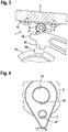
- FIG 3 is a view similar to 2 and shows the parking lock 1 in an axial view after the cam 7, starting from the position in 1 position shown has been rotated clockwise.
- the tip 11 of the cam 7 slides along the outside along the pawl 12.
- the pawl 12 is moved away from the parking lock wheel 14 in the direction of the cam 7 under the action of the spring acting on the pawl 12.
- the projection 15 of the pawl 12 is outside of the recess 13 of the parking lock wheel 14, so that rotation of the parking lock wheel 14 is no longer blocked. Accordingly, the wheel of the motor vehicle coupled to the parking lock wheel 14 can then be moved.
- the cam 7 can be converted from the release state to the locked state by rotating the selector shaft 3 counterclockwise.
- the selector shaft 3 transmits the torque to the cam 7 via the torsion spring 8.
- the projection 15 of the pawl 12 is not located above a recess 13 of the parking lock wheel 14 , the projection cannot be moved into the recess; instead, it then rests on the outer circumference of the parking lock wheel 1 .
- the torque transmitted by the selector shaft 3 then causes the torsion spring 8 to be tensioned, i.e. potential energy is stored in the torsion spring 8 . If the vehicle in which the parking lock is arranged rolls further, the parking lock wheel 14 rotates. Under the action of the biasing force generated by the torsion spring 8, the pawl 12 is then pressed into the next recess 13, so that the parking lock 1 in the locked state.
- FIG. 4 12 is an axial view of cam 7 located on selector shaft 3.
- FIG. It can be seen that the cam 7 has a through opening 16 which is adapted to the outer diameter of the selector shaft 3 in this area.
- the torsion spring 8 can be hooked into a second, smaller passage opening 17 of the cam 7 .
- the cam 7 has a stop 18 so that the cam 7 is directly, ie without the involvement of the torsion spring 8, transferred from the blocked state to the released state when the selector shaft 3 rotates clockwise.
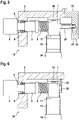
- FIG 5 13 is a partially sectioned view showing a second embodiment of a parking lock 19, identical components being denoted by identical reference numerals.
- the parking lock 19 comprises the selector shaft 3 which partially penetrates the transmission housing 2 and which is predominantly accommodated in the transmission housing 2 .
- the selector shaft 3 is driven by the electric drive motor 4 .
- the coupled to the shift shaft 3 cam 7 is used to block the pawl 12 of the parking lock wheel 14.
- a spacer sleeve 20 is arranged at the right end of the selector shaft 3 and is mounted in a blind hole 22 of a gear housing cover 23 by means of a bearing 21 . Due to this support at its end opposite the drive, the selector shaft 3 can transmit a higher torque.
- 6 12 shows a third exemplary embodiment of a parking lock 24, identical components again being provided with the same reference symbols as in the preceding exemplary embodiments.
- the selector shaft 3 accommodated in the transmission housing 2 is at its free, in 6 mounted on the right end in a plate 25 which is arranged perpendicular to the longitudinal direction of the selector shaft 3.
- the plate 25 is fixed to the plate 10, which is located on the inside of the transmission case 2, and has a circular opening into which an end portion 26 of the selector shaft 3 is inserted and supported. With this support, the selector shaft 3 is able to transmit a higher torque.
Landscapes
- Engineering & Computer Science (AREA)
- General Engineering & Computer Science (AREA)
- Mechanical Engineering (AREA)
- Gear-Shifting Mechanisms (AREA)
Abstract
Description
- Die Erfindung betrifft eine Parksperre für ein Kraftfahrzeug, mit einem bewegbaren Arretierungsmittel zum Beaufschlagen eines im Inneren eines Getriebegehäuses angeordneten Parksperrenrads mit einer Haltekraft.
- Parksperren, die auch als Parkbremsen bezeichnet werden, werden in steigendem Maße bei Kraftfahrzeugen eingesetzt. Ein bewegbares Arretierungsmittel wirkt dabei auf ein Parksperrenrad, das über Getriebekomponenten mit einem Rad des Kraftfahrzeugs verbunden ist. Im gesperrten Zustand blockiert die Parksperre das Rad des Kraftfahrzeugs.
- Bei der in dem Dokument
WO 2017/216230 A1 beschriebenen gattungsgemäßen Parksperre sind ein Stößel und dessen Antrieb innerhalb eines Getriebegehäuses angeordnet. Der Stößel wirkt mit einem einseitig gelagerten Hebel zusammen, der einen Vorsprung aufweist, der durch eine Betätigung des Stößels in eine Ausnehmung eines Parksperrenrads geschwenkt werden kann. - Ein derartiger Aufbau ist allerdings aufwendig. Sowohl für das Innere des Getriebegehäuses als auch für die Außenseite wird jeweils ein separater Kabelbaum benötigt. Darüber hinaus muss verhindert werden, dass durch Druckunterschiede zwischen dem Inneren des Getriebegehäuses und der Parkbremse Getriebeöl in die Parkbremse, insbesondere in deren elektrischen Antrieb, eindringt. Allerdings entsteht durch eine derartige Ausgestaltung ein erhöhter baulicher Aufwand.
- Der Erfindung liegt die Aufgabe zugrunde, eine Parksperre für ein Kraftfahrzeug anzugeben, die einfach aufgebaut ist und eine zuverlässige Funktion sicherstellt.
- Zur Lösung dieser Aufgabe ist bei einer Parksperre der eingangs genannten Art erfindungsgemäß vorgesehen, dass das bewegbare Arretierungsmittel mittels einer durch einen Antriebsmotor drehbaren Schaltwelle und einen mit der Schaltwelle gekoppelten Nocken zwischen einem Freigabezustand, in dem das Parksperrenrad drehbar ist und einem gesperrten Zustand, in dem eine Drehung des Parksperrenrads blockiert ist, verschwenkbar ist, wobei der Antriebsmotor außerhalb des Getriebegehäuses angeordnet ist, die Schaltwelle das Getriebegehäuse durchsetzt und der Nocken innerhalb des Getriebegehäuses angeordnet ist.
- Die Erfindung beruht auf der Erkenntnis, dass der Antrieb der Parksperre, insbesondere ein elektrischer Antrieb, besonders zuverlässig vor dem Eindringen von Getriebeöl geschützt werden kann, indem der Antriebsmotor außerhalb des Getriebegehäuses angeordnet ist. Die durch den Antriebsmotor angetriebene Schaltwelle erstreckt sich durch das Getriebegehäuse nach innen und trägt den verschwenkbaren Nocken. Dadurch wird lediglich ein einziger Kabelbaum benötigt, der außerhalb des Getriebegehäuses angeordnet ist. Eine separate Entlüftung der Parksperre ist nicht erforderlich. Die erfindungsgemäße Parksperre ist somit einfach aufgebaut und gewährleistet eine zuverlässige Funktion.
- Eine Weiterbildung der Erfindung sieht vor, dass die Schaltwelle von einer Torsionsfeder umgeben ist, die einerseits an der Schaltwelle und andererseits an dem Nocken befestigt ist. Beim Verschwenken der Schaltwelle von dem Freigabezustand in den gesperrten Zustand bewegt die Torsionsfeder den Nocken, der das Parksperrenrad blockiert.
- Das Drehmoment wird von der Schaltwelle über die Torsionsfeder auf den Nocken übertragen, wenn die Parksperre von der ungebremsten, inaktiven Position, d.h. dem Freigabezustand, in die gebremste Position, d.h. den gesperrten Zustand, bewegt wird. Der Nocken kann somit durch eine Drehung der Schaltwelle in eine (erste) Drehrichtung durch die Torsionsfeder von dem Freigabezustand in den gesperrten Zustand überführt werden.
- Im Rahmen der Erfindung wird es bevorzugt, dass an der Schaltwelle ein Anschlag angeordnet ist. Der Anschlag ermöglich, dass der Nocken durch eine Drehung der Schaltwelle in die entgegengesetzte Drehrichtung von dem gesperrten Zustand in den Freigabezustand überführbar ist.
- Im Rahmen der Erfindung kann es vorgesehen sein, dass der Nocken eine an den Außendurchmesser der Schaltwelle angepasste Durchgangsöffnung aufweist. Der Nocken ist somit separat von der Schaltwelle ausgebildet und zumindest abschnittsweise um die Schaltwelle herum drehbar. Der Nocken und die Schaltwelle sind über die Torsionsfeder miteinander gekoppelt.
- Um einen besonders reibungsarmen Betrieb der erfindungsgemäßen Parksperre zu gewährleisten, kann es vorgesehen sein, dass die Schaltwelle durch ein Gleitlager oder ein Wälzlager am oder im Getriebegehäuse gelagert ist. Die Lagerung der Schaltwelle bewirkt eine Verringerung der Reibung und in der Folge einen reduzierten Antriebsbedarf des elektrischen Antriebs.
- Eine Ausgestaltung der Erfindung sieht vor, dass die Schaltwelle gegenüber dem Getriebegehäuse durch ein Dichtungselement abgedichtet ist. Das Dichtungselement verhindert das Eindringen von Verschmutzungen in das Innere des Getriebegehäuses, gleichzeitig wird der Austritt von Getriebeöl durch das Getriebegehäuse nach außen verhindert.
- Die erfindungsgemäße Parksperre kann eine besonders hohe Haltekraft aufbringen, wenn die Schaltwelle mit ihrem dem Antriebsmotor entgegengesetzten freien Ende im Getriebegehäuse gelagert ist. Vorzugsweise ist das freie Ende der Schaltwelle durch ein Wälzlager oder ein Gleitlager in einem Sackloch des Getriebegehäuses oder eines Getriebedeckels gelagert. Das freie Ende der Schaltwelle kann auch mit einer Distanzhülse versehen sein, wodurch die Schaltwelle in Axialrichtung positioniert wird.
- Die Erfindung betrifft auch ein Getriebe mit einer Parksperre der beschriebenen Art.
- Daneben betrifft die Erfindung eine Antriebseinrichtung für ein elektrisch antreibbares Kraftfahrzeug, umfassend eine elektrische Maschine, ein mit der elektrischen Maschine gekoppeltes Getriebe und eine Parksperre der beschriebenen Art.
- Die Erfindung wird nachfolgend anhand von Ausführungsbeispielen unter Bezugnahme auf die Zeichnungen erläutert. Die Zeichnungen sind schematische Darstellungen und zeigen:
- Fig. 1
- die wesentlichen Komponenten einer erfindungsgemäßen Parksperre in einem Getriebegehäuse;
- Fig. 2
- eine axiale Ansicht der Parksperre bei blockiertem Parksperrenrad;
- Fig. 3
- die in
Fig. 2 gezeigte Parksperre im Freigabezustand; - Fig. 4
- eine vergrößerte Ansicht des auf der Schaltwelle angeordneten Nockens in Längsrichtung der Schaltwelle gesehen;
- Fig. 5
- eine axiale Ansicht eines weiteren Ausführungsbeispiels einer erfindungsgemäßen Parksperre; und
- Fig. 6
- eine axiale Ansicht eines weiteren Ausführungsbeispiels einer erfindungsgemäßen Parksperre.
-
Fig. 1 zeigt eine Parksperre 1, die in einem Getriebegehäuse 2 angeordnet ist. Die Parksperre 1 umfasst eine Schaltwelle 3, die durch einen elektrischen Antriebsmotor 4 drehbar ist. Die Schaltwelle 3 ist dazu mit einer Antriebswelle des Antriebsmotors 4 gekoppelt. InFig. 1 erkennt man, dass der elektrische Antriebsmotor 4 außerhalb des geschnitten dargestellten Getriebegehäuses 2 angeordnet ist. Die Schaltwelle 3 durchsetzt eine Öffnung 5 des Getriebegehäuses 2. Der größte Teil der Schaltwelle 3, abgesehen von dem unmittelbar an den elektrischen Antriebsmotor 4 angrenzenden Teil, ist innerhalb des Getriebegehäuses 2 angeordnet. Die Öffnung 5 ist durch ein Dichtungselement 6 abgedichtet. Das Dichtungselement 6 dichtet einen Ringraum zwischen der Öffnung 5 des Getriebegehäuses 2 und der Außenseite der Schaltwelle 3 ab. - Auf der Schaltwelle 3 ist ein Nocken 7 angeordnet, wobei die Schaltwelle 3 und der Nocken 7 als separate Komponenten ausgebildet sind. Der Nocken 7 weist eine Durchgangsöffnung auf, die an den Außendurchmesser der Schaltwelle 3 angepasst ist, sodass der Nocken 7 auf den Endabschnitt der Schaltwelle 3 geschoben werden kann. Die Schaltwelle 3 ist von einer Torsionsfeder 8 umgeben. Ein Ende der Torsionsfeder 8 (das in
Fig. 1 linke Ende) stützt sich an der Schaltwelle 3 ab und ist an der Schaltwelle 3 befestigt. Das entgegengesetzte Ende der Torsionsfeder 8 (das inFig. 1 rechte Ende) stützt sich an dem Nocken 7 ab und ist an dem Nocken 7 befestigt. Im Bereich ihres freien Endes weist die Schaltwelle 3 eine Scheibe 9 auf, die den Nocken 7 in Axialrichtung fixiert. -
Fig. 2 zeigt die Parksperre 1 in einer axialen Ansicht, d. h. in Längsrichtung der Schaltwelle 3. An der Innenseite des Getriebegehäuses 2 befindet sich eine aus einer Stahllegierung hergestellte Platte 10. Die Platte 10 ist zwischen dem Nocken 7 und der Innenseite des Getriebegehäuses 2 angeordnet und liegt dem Nocken 7 gegenüber. Bei einer Drehung des Nockens 7 berührt dieser die Platte 10, d.h. der Nocken 7 wälzt sich auf der Platte 10 ab, er berührt jedoch nicht das Getriebegehäuse 2. -
Fig. 2 zeigt den Nocken 7 näherungsweise in seiner maximal "ausgefahrenen" Stellung, in der sich die Spitze des Nockens 7 in seiner untersten Position befindet. Der Nocken 7 berührt mit seiner Spitze 11 ein bewegbares Arretierungsmittel, das als Sperrklinke ausgebildet ist. Ein Ende (nicht dargestellt) der Sperrklinke 12 ist schwenkbar gelagert. Die Sperrklinke 12 weist in der Nähe ihres freien Endes einen quer abstehenden Vorsprung 15 auf. Wenn der Nocken 7 die Sperrklinke 12 schwenkt, wird der Vorsprung 15 der Sperrklinke 12 gegen die Kraft einer Feder (nicht gezeigt) in eine Ausnehmung 13 eines Parksperrenrads 14 bewegt. Der Vorsprung 15 der Sperrklinke 12 blockiert in diesem Zustand eine Drehung des Parksperrenrads 14, das über ein Getriebe mit einem Rad des Kraftfahrzeugs gekoppelt ist. In dem inFig. 2 gezeigten blockierten Zustand verhindert die Parksperre 1 eine Drehung des Rads des Kraftfahrzeugs. Eine Steuerungseinrichtung (nicht gezeigt) dient zur Steuerung des elektrischen Antriebsmotors 4, durch den die Schaltwelle 3 und in der Folge der Nocken 7 angetrieben werden. -
Fig. 3 ist eine ähnliche Ansicht wieFig. 2 und zeigt die Parksperre 1 in einer axialen Ansicht, nachdem der Nocken 7 ausgehend von der inFig. 1 gezeigten Position im Uhrzeigersinn gedreht worden ist. Die Spitze 11 des Nockens 7 gleitet dabei außenseitig entlang der Sperrklinke 12. Dadurch wird die Sperrklinke 12 unter der Wirkung der auf die Sperrklinke 12 wirkenden Feder von dem Parksperrenrad 14 weg in Richtung des Nockens 7 bewegt. In diesem Zustand befindet sich der Vorsprung 15 der Sperrklinke 12 außerhalb der Ausnehmung 13 des Parksperrenrads 14, sodass eine Drehung des Parksperrenrads 14 nicht mehr blockiert wird. Dementsprechend kann dann das mit dem Parksperrenrad 14 gekoppelte Rad des Kraftfahrzeugs bewegt werden. -
Fig. 3 zeigt die Parksperre 1 somit im nicht aktiven Zustand (Freigabezustand), währendFig. 2 die Parksperre 1 im gesperrten Zustand zeigt, in dem eine Drehung des Parksperrenrads 14 blockiert ist. Ausgehend von dem inFig. 3 gezeigten Zustand kann der Nocken 7 durch eine Drehung der Schaltwelle 3 gegen den Uhrzeigersinn von dem Freigabezustand in den gesperrten Zustand überführt werden. Die Schaltwelle 3 übertragt das Drehmoment dabei über die Torsionsfeder 8 an den Nocken 7. - Falls der Vorsprung 15 der Sperrklinke 12 sich dabei nicht oberhalb einer Ausnehmung 13 des Parksperrenrads 14 befindet, kann der Vorsprung nicht in die Ausnehmung bewegt werden, stattdessen liegt er dann auf dem Außenumfang des Parksperrenrads 1 auf. Das von der Schaltwelle 3 übertragene Drehmoment bewirkt dann, dass die Torsionsfeder 8 gespannt wird, d.h. in der Torsionsfeder 8 wird potenzielle Energie gespeichert. Wenn das Fahrzeug, in dem die Parksperre angeordnet ist, weiter rollt, dreht sich das Parksperrenrad 14. Unter der Wirkung der von der Torsionsfeder 8 erzeugten Vorspannkraft wird die Sperrklinke 12 dann in die nächste Ausnehmung 13 gedrückt, so dass sich die Parksperre 1 in dem gesperrten Zustand befindet.
-
Fig. 4 ist eine axiale Ansicht des Nockens 7, der sich auf der Schaltwelle 3 befindet. Man erkennt, dass der Nocken 7 eine Durchgangsöffnung 16 besitzt, die an den Außendurchmesser der Schaltwelle 3 in diesem Bereich angepasst ist. In eine zweite, kleinere Durchgangsöffnung 17 des Nockens 7 kann die Torsionsfeder 8 eingehängt werden. InFig. 4 erkennt man, dass der Nocken 7 einen Anschlag 18 aufweist, sodass der Nocken 7 bei einer Drehung der Schaltwelle 3 im Uhrzeigersinn direkt, d.h. ohne Mitwirkung der Torsionsfeder 8, von dem gesperrten Zustand in den Freigabezustand überführt wird. -
Fig. 5 ist eine teilweise geschnittene Ansicht und zeigt ein zweites Ausführungsbeispiel einer Parksperre 19, wobei identische Komponenten mit identischen Bezugszeichen bezeichnet werden. Die Parksperre 19 umfasst in Übereinstimmung mit dem ersten Ausführungsbeispiel die Schaltwelle 3, die das Getriebegehäuse 2 teilweise durchsetzt und die überwiegend in dem Getriebegehäuse 2 aufgenommen ist. Die Schaltwelle 3 wird durch den elektrischen Antriebsmotor 4 angetrieben. Der mit der Schaltwelle 3 gekoppelte Nocken 7 dient zum Blockieren der Sperrklinke 12 des Parksperrenrads 14. An dem inFig. 5 rechten Ende der Schaltwelle 3 ist eine Abstandshülse 20 angeordnet, die mittels eines Lagers 21 in einem Sackloch 22 eines Getriebegehäusedeckels 23 gelagert ist. Durch diese Abstützung an ihrem dem Antrieb entgegengesetzten Ende kann die Schaltwelle 3 ein höheres Drehmoment übertragen. -
Fig. 6 zeigt ein drittes Ausführungsbeispiel einer Parksperre 24, wobei wiederum identische Komponenten mit denselben Bezugszeichen wie in den vorangehenden Ausführungsbeispielen versehen sind. Die in dem Getriebegehäuse 2 aufgenommene Schaltwelle 3 ist an ihrem freien, inFig. 6 rechten Ende in einer Platte 25 gelagert, die senkrecht zur Längsrichtung der Schaltwelle 3 angeordnet ist. Die Platte 25 ist an der Platte 10, die sich an der Innenseite des Getriebegehäuses 2 befindet, befestigt und weist eine kreisförmige Öffnung auf, in die ein Endabschnitt 26 der Schaltwelle 3 eingesetzt und gelagert ist. Durch diese Abstützung ist die Schaltwelle 3 in der Lage, ein höheres Drehmoment zu übertragen.
Claims (12)
- Parksperre (1, 19, 24) für ein Kraftfahrzeug, mit einem bewegbaren Arretierungsmittel zum Beaufschlagen eines im Inneren eines Getriebegehäuses (2) angeordneten Parksperrenrads (14) mit einer Haltekraft, dadurch gekennzeichnet, dass das bewegbare Arretierungsmittel mittels einer durch einen Antriebsmotor (4) drehbaren Schaltwelle (3) und einen mit der Schaltwelle (3) gekoppelten Nocken (7) zwischen einem Freigabezustand, in dem das Parksperrenrad (14) drehbar ist und einem gesperrten Zustand, in dem eine Drehung des Parksperrenrads (14) blockiert ist, verschwenkbar ist, wobei der Antriebsmotor (4) außerhalb des Getriebegehäuses (2) angeordnet ist, die Schaltwelle (3) das Getriebegehäuse (2) durchsetzt und der Nocken (7) innerhalb des Getriebegehäuses (2) angeordnet ist.
- Parksperre nach Anspruch 1, wobei die Schaltwelle (3) von einer Torsionsfeder (8) umgeben ist, die einerseits an der Schaltwelle (3) und andererseits an dem Nocken (7) befestigt ist.
- Parksperre nach Anspruch 2, wobei der Nocken (7) durch eine Drehung der Schaltwelle (3) in eine Drehrichtung durch die Torsionsfeder (8) von dem Freigabezustand in den gesperrten Zustand überführbar ist.
- Parksperre nach Anspruch 3, wobei der Nocken (7) durch die Schaltwelle (3) in die entgegengesetzte Drehrichtung mittels eines an der Schaltwelle (3) angeordneten Anschlags (18) von dem gesperrten Zustand in den Freigabezustand überführbar ist.
- Parksperre nach einem der vorangehenden Ansprüche, wobei der Nocken (7) im gesperrten Zustand eine Sperrklinke (12) beaufschlagt und in eine Ausnehmung (13) des Parksperrenrads (14) drückt.
- Parksperre nach Anspruch 5, wobei in dem Fall, wenn die Sperrklinke (12) nicht einer Ausnehmung (13) des Parksperrenrads (14) gegenüberliegt, ein von der Schaltwelle übertragenes Drehmoment als potenzielle Energie in der Torsionsfeder (8) gespeichert wird, wobei die Sperrklinke (12) bei einer weiteren Drehung des Parksperrenrads (14) in die Ausnehmung (13) des Parksperrenrads (14) gedrückt wird.
- Parksperre nach einem der vorangehenden Ansprüche, wobei der Nocken (7) eine an den Außendurchmesser der Schaltwelle (3) angepasste Durchgangsöffnung (16) aufweist.
- Parksperre nach einem der vorangehenden Ansprüche, wobei die Schaltwelle (3) durch ein Gleitlager oder ein Wälzlager am oder im Getriebegehäuse (2) gelagert ist.
- Parksperre nach einem der vorangehenden Ansprüche, wobei die Schaltwelle (3) gegenüber dem Getriebegehäuse (2) durch ein Dichtungselement (6) abgedichtet ist.
- Parksperre nach einem der vorangehenden Ansprüche, wobei die Schaltwelle (3) mit ihrem dem Antriebsmotor (4) entgegengesetzten freien Ende im Getriebegehäuse (2) gelagert ist.
- Getriebe, umfassend eine Parksperre (1, 19, 24) nach einem der Ansprüche 1 bis 10.
- Antriebseinrichtung für ein elektrisch antreibbares Kraftfahrzeug, umfassend- eine elektrische Maschine,- ein mit der elektrischen Maschine gekoppeltes Getriebe und eine Parksperre (1, 19, 24) nach einem der Ansprüche 1 bis 10.
Applications Claiming Priority (1)
| Application Number | Priority Date | Filing Date | Title |
|---|---|---|---|
| DE102020214420.6A DE102020214420A1 (de) | 2020-11-17 | 2020-11-17 | Parksperre, Getriebe und Antriebseinrichtung |
Publications (2)
| Publication Number | Publication Date |
|---|---|
| EP4001705A1 true EP4001705A1 (de) | 2022-05-25 |
| EP4001705B1 EP4001705B1 (de) | 2024-04-17 |
Family
ID=78649189
Family Applications (1)
| Application Number | Title | Priority Date | Filing Date |
|---|---|---|---|
| EP21208332.3A Active EP4001705B1 (de) | 2020-11-17 | 2021-11-15 | Parksperre, getriebe und antriebseinrichtung |
Country Status (4)
| Country | Link |
|---|---|
| US (1) | US11821514B2 (de) |
| EP (1) | EP4001705B1 (de) |
| CN (1) | CN114508590A (de) |
| DE (1) | DE102020214420A1 (de) |
Families Citing this family (4)
| Publication number | Priority date | Publication date | Assignee | Title |
|---|---|---|---|---|
| DE102019132496A1 (de) * | 2019-11-29 | 2021-06-02 | Valeo Siemens Eautomotive Germany Gmbh | Getriebeeinrichtung für ein elektrisch antreibbares Fahrzeug, Antriebseinrichtung für ein elektrisch antreibbares Fahrzeug und Fahrzeug |
| US11719337B2 (en) * | 2021-03-26 | 2023-08-08 | Dana Heavy Vehicle Systems Group, Llc | Methods and systems for a parking mechanism |
| US12085166B1 (en) * | 2023-04-06 | 2024-09-10 | Dana Heavy Vehicle Systems Group, Llc | Externally mounted parking system |
| US20260063203A1 (en) * | 2024-08-29 | 2026-03-05 | Dana Graziano S.R.L. | Park lock system |
Citations (7)
| Publication number | Priority date | Publication date | Assignee | Title |
|---|---|---|---|---|
| CN102135176A (zh) * | 2011-03-30 | 2011-07-27 | 重庆青山工业有限责任公司 | 电动汽车的驻车机构 |
| DE102014117731A1 (de) * | 2013-12-06 | 2015-06-11 | GM Global Technology Operations LLC (n. d. Ges. d. Staates Delaware) | Fahrzeug und arretierungsbaugruppe für das fahrzeug |
| WO2017216230A1 (de) | 2016-06-16 | 2017-12-21 | Valeo Siemens Eautomotive Germany Gmbh | Parkbremse und betriebsverfahren |
| CN108317247A (zh) * | 2018-03-20 | 2018-07-24 | 株洲欧格瑞传动股份有限公司 | 驻车机构及汽车 |
| EP3527857A1 (de) * | 2016-10-14 | 2019-08-21 | NTN Corporation | Radinterne motorantriebsvorrichtung |
| WO2019167993A1 (ja) * | 2018-03-01 | 2019-09-06 | Ntn株式会社 | インホイールモータ駆動装置 |
| CN111810631A (zh) * | 2019-04-11 | 2020-10-23 | 广州汽车集团股份有限公司 | 驻车装置及变速器 |
Family Cites Families (17)
| Publication number | Priority date | Publication date | Assignee | Title |
|---|---|---|---|---|
| JPS4917163B1 (de) * | 1970-01-17 | 1974-04-27 | ||
| JPH11303991A (ja) * | 1998-04-20 | 1999-11-02 | Yamaha Motor Co Ltd | 車両のパーキングブレーキ装置 |
| DE10101363C1 (de) | 2001-01-13 | 2002-10-02 | Zf Sachs Ag | Parksperrenbetätigungseinrichtung für eine Parksperrenvorrichtung eines Kraftfahrzeuges |
| JP2009041679A (ja) * | 2007-08-09 | 2009-02-26 | Toyota Motor Corp | アクチュエータ、自動変速機のレンジ切替装置、ならびにパーキング装置 |
| JP4752961B2 (ja) * | 2009-07-13 | 2011-08-17 | マツダ株式会社 | 変速機のパーキング装置 |
| CN104019227B (zh) | 2014-06-20 | 2017-01-18 | 重庆长安汽车股份有限公司 | 机动车辆驻车锁止机构 |
| CN109642668B (zh) | 2016-06-29 | 2020-12-08 | Gkn动力传动布伦耐克股份公司 | 停车闭锁单元和带有停车闭锁装置的电驱动组件 |
| JP2019006195A (ja) * | 2017-06-22 | 2019-01-17 | Ntn株式会社 | 車両用駆動装置 |
| CN107606146A (zh) * | 2017-10-25 | 2018-01-19 | 上海伊控动力系统有限公司 | 一种变速器驻车操纵装置 |
| CN208530537U (zh) * | 2018-06-06 | 2019-02-22 | 中国第一汽车股份有限公司 | 一种电动车减速器驻车制动机构 |
| CN208845705U (zh) * | 2018-06-08 | 2019-05-10 | 中国第一汽车股份有限公司 | 一种新型的变速器驻车凸轮机构 |
| CN208793609U (zh) * | 2018-08-22 | 2019-04-26 | 上海汽车变速器有限公司 | 用于新能源减速器的驻车锁止装置 |
| DE102018216728A1 (de) | 2018-09-28 | 2020-04-02 | Robert Bosch Gmbh | Elektromechanische Parksperre |
| JP7059907B2 (ja) * | 2018-11-28 | 2022-04-26 | トヨタ自動車株式会社 | パーキングロック装置 |
| DE102019134432A1 (de) | 2019-01-10 | 2020-07-16 | Schaeffler Technologies AG & Co. KG | Aktoreinrichtung für eine Parksperre |
| CN111720539B (zh) | 2019-03-21 | 2021-09-07 | 上海汽车变速器有限公司 | 凸轮锁止式的变速器驻车机构 |
| CN110425277B (zh) | 2019-06-26 | 2020-08-28 | 南昌大学 | 一种p挡驻车机械系统 |
-
2020
- 2020-11-17 DE DE102020214420.6A patent/DE102020214420A1/de active Pending
-
2021
- 2021-11-15 EP EP21208332.3A patent/EP4001705B1/de active Active
- 2021-11-15 US US17/454,875 patent/US11821514B2/en active Active
- 2021-11-17 CN CN202111360486.6A patent/CN114508590A/zh active Pending
Patent Citations (7)
| Publication number | Priority date | Publication date | Assignee | Title |
|---|---|---|---|---|
| CN102135176A (zh) * | 2011-03-30 | 2011-07-27 | 重庆青山工业有限责任公司 | 电动汽车的驻车机构 |
| DE102014117731A1 (de) * | 2013-12-06 | 2015-06-11 | GM Global Technology Operations LLC (n. d. Ges. d. Staates Delaware) | Fahrzeug und arretierungsbaugruppe für das fahrzeug |
| WO2017216230A1 (de) | 2016-06-16 | 2017-12-21 | Valeo Siemens Eautomotive Germany Gmbh | Parkbremse und betriebsverfahren |
| EP3527857A1 (de) * | 2016-10-14 | 2019-08-21 | NTN Corporation | Radinterne motorantriebsvorrichtung |
| WO2019167993A1 (ja) * | 2018-03-01 | 2019-09-06 | Ntn株式会社 | インホイールモータ駆動装置 |
| CN108317247A (zh) * | 2018-03-20 | 2018-07-24 | 株洲欧格瑞传动股份有限公司 | 驻车机构及汽车 |
| CN111810631A (zh) * | 2019-04-11 | 2020-10-23 | 广州汽车集团股份有限公司 | 驻车装置及变速器 |
Also Published As
| Publication number | Publication date |
|---|---|
| US20220154823A1 (en) | 2022-05-19 |
| CN114508590A (zh) | 2022-05-17 |
| EP4001705B1 (de) | 2024-04-17 |
| DE102020214420A1 (de) | 2022-05-19 |
| US11821514B2 (en) | 2023-11-21 |
Similar Documents
| Publication | Publication Date | Title |
|---|---|---|
| EP4001705B1 (de) | Parksperre, getriebe und antriebseinrichtung | |
| DE19627646C2 (de) | Aktuatorenbaugruppe für eine Fahrzeugbremse und Fahrzeugbremse mit einer derartigen Aktuatorenbaugruppe | |
| WO2020103970A1 (de) | Parksperre für ein kraftfahrzeug | |
| EP2785568B1 (de) | Federspeicherbremszylinder mit notlöseeinrichtung | |
| DE102017218747A1 (de) | Parksperre eines Automatgetriebes für ein Kraftfahrzeug | |
| DE2608502B2 (de) | Lösevorrichtung für die Unterbrechung und automatische Rückführung der Betriebsfunktion eines Federspeicherbremszyiinders | |
| EP1576303A1 (de) | Bremsmechanismus für eine scheibenbremse | |
| EP1388682A1 (de) | Drehmomentübertragungsvorrichtung in einem Kraftfahrzeug | |
| EP4179235B1 (de) | Parksperrenvorrichtung für ein fahrzeuggetriebe sowie fahrzeuggetriebe | |
| DE19648581B4 (de) | Scheibenbremse mit Feststellbremsfunktion | |
| DE102017008196A1 (de) | Trommelbremse mit einem elektromechanisch-hydraulischen Bremsaktuator | |
| EP4130518A2 (de) | Schaltgetriebesperre zur parkunterstützung | |
| DE102021129954A1 (de) | Trägerbaugruppe und Antriebsbaugruppe für eine Aktorbaugruppe für eine Fahrzeugbremse sowie Aktorbaugruppe | |
| DE2116175C2 (de) | Nachstellvorrichtung für eine Fahrzeugbremse | |
| DE102018204507B4 (de) | Parksperre für ein Kraftfahrzeug, insbesondere für einen Kraftwagen, Verfahren zum Betreiben einer solchen Parksperre, Getriebe und Kraftfahrzeug | |
| DE112020002730T5 (de) | Elektrische Bremsvorrichtung | |
| WO2012037916A1 (de) | Umschlingungsbremsvorrichtung für planetengetriebe und planetengetriebe mit umschlingungsbremsvorrichtung | |
| DE102019207075B3 (de) | Parksperrensystem | |
| DE102017202443A1 (de) | Parksperrenklinke für eine Getriebeparksperre | |
| EP4019812A1 (de) | Parksperre und getriebe mit einer parksperre | |
| DE2031501A1 (de) | Selbsttätige Nachstellvorrichtung fur Innenbackenbremsen | |
| EP2963190B1 (de) | Dreh- und Schwenkvorrichtung für eine Baumaschine | |
| DE102006016666A1 (de) | Vorrichtung zur Betätigung einer Kupplung | |
| DE102021206229A1 (de) | Betätigungseinheit für eine Fahrzeugbremse und Fahrzeugbremse | |
| DE102008000481A1 (de) | Parksperre für ein Getriebe |
Legal Events
| Date | Code | Title | Description |
|---|---|---|---|
| PUAI | Public reference made under article 153(3) epc to a published international application that has entered the european phase |
Free format text: ORIGINAL CODE: 0009012 |
|
| STAA | Information on the status of an ep patent application or granted ep patent |
Free format text: STATUS: EXAMINATION IS IN PROGRESS |
|
| 17P | Request for examination filed |
Effective date: 20211115 |
|
| AK | Designated contracting states |
Kind code of ref document: A1 Designated state(s): AL AT BE BG CH CY CZ DE DK EE ES FI FR GB GR HR HU IE IS IT LI LT LU LV MC MK MT NL NO PL PT RO RS SE SI SK SM TR |
|
| RAP3 | Party data changed (applicant data changed or rights of an application transferred) |
Owner name: VALEO EAUTOMOTIVE GERMANY GMBH |
|
| P01 | Opt-out of the competence of the unified patent court (upc) registered |
Effective date: 20230528 |
|
| GRAP | Despatch of communication of intention to grant a patent |
Free format text: ORIGINAL CODE: EPIDOSNIGR1 |
|
| STAA | Information on the status of an ep patent application or granted ep patent |
Free format text: STATUS: GRANT OF PATENT IS INTENDED |
|
| RIC1 | Information provided on ipc code assigned before grant |
Ipc: F16H 57/023 20120101ALN20231103BHEP Ipc: F16H 57/02 20120101ALN20231103BHEP Ipc: F16H 63/30 20060101ALN20231103BHEP Ipc: F16H 63/34 20060101AFI20231103BHEP |
|
| INTG | Intention to grant announced |
Effective date: 20231120 |
|
| GRAS | Grant fee paid |
Free format text: ORIGINAL CODE: EPIDOSNIGR3 |
|
| GRAA | (expected) grant |
Free format text: ORIGINAL CODE: 0009210 |
|
| STAA | Information on the status of an ep patent application or granted ep patent |
Free format text: STATUS: THE PATENT HAS BEEN GRANTED |
|
| AK | Designated contracting states |
Kind code of ref document: B1 Designated state(s): AL AT BE BG CH CY CZ DE DK EE ES FI FR GB GR HR HU IE IS IT LI LT LU LV MC MK MT NL NO PL PT RO RS SE SI SK SM TR |
|
| REG | Reference to a national code |
Ref country code: GB Ref legal event code: FG4D Free format text: NOT ENGLISH |
|
| REG | Reference to a national code |
Ref country code: CH Ref legal event code: EP |
|
| REG | Reference to a national code |
Ref country code: DE Ref legal event code: R096 Ref document number: 502021003373 Country of ref document: DE |
|
| REG | Reference to a national code |
Ref country code: IE Ref legal event code: FG4D Free format text: LANGUAGE OF EP DOCUMENT: GERMAN |
|
| REG | Reference to a national code |
Ref country code: LT Ref legal event code: MG9D |
|
| REG | Reference to a national code |
Ref country code: NL Ref legal event code: MP Effective date: 20240417 |
|
| PG25 | Lapsed in a contracting state [announced via postgrant information from national office to epo] |
Ref country code: NL Free format text: LAPSE BECAUSE OF FAILURE TO SUBMIT A TRANSLATION OF THE DESCRIPTION OR TO PAY THE FEE WITHIN THE PRESCRIBED TIME-LIMIT Effective date: 20240417 |
|
| PG25 | Lapsed in a contracting state [announced via postgrant information from national office to epo] |
Ref country code: NL Free format text: LAPSE BECAUSE OF FAILURE TO SUBMIT A TRANSLATION OF THE DESCRIPTION OR TO PAY THE FEE WITHIN THE PRESCRIBED TIME-LIMIT Effective date: 20240417 |
|
| PG25 | Lapsed in a contracting state [announced via postgrant information from national office to epo] |
Ref country code: IS Free format text: LAPSE BECAUSE OF FAILURE TO SUBMIT A TRANSLATION OF THE DESCRIPTION OR TO PAY THE FEE WITHIN THE PRESCRIBED TIME-LIMIT Effective date: 20240817 |
|
| PG25 | Lapsed in a contracting state [announced via postgrant information from national office to epo] |
Ref country code: BG Free format text: LAPSE BECAUSE OF FAILURE TO SUBMIT A TRANSLATION OF THE DESCRIPTION OR TO PAY THE FEE WITHIN THE PRESCRIBED TIME-LIMIT Effective date: 20240417 |
|
| PG25 | Lapsed in a contracting state [announced via postgrant information from national office to epo] |
Ref country code: HR Free format text: LAPSE BECAUSE OF FAILURE TO SUBMIT A TRANSLATION OF THE DESCRIPTION OR TO PAY THE FEE WITHIN THE PRESCRIBED TIME-LIMIT Effective date: 20240417 Ref country code: FI Free format text: LAPSE BECAUSE OF FAILURE TO SUBMIT A TRANSLATION OF THE DESCRIPTION OR TO PAY THE FEE WITHIN THE PRESCRIBED TIME-LIMIT Effective date: 20240417 |
|
| PG25 | Lapsed in a contracting state [announced via postgrant information from national office to epo] |
Ref country code: GR Free format text: LAPSE BECAUSE OF FAILURE TO SUBMIT A TRANSLATION OF THE DESCRIPTION OR TO PAY THE FEE WITHIN THE PRESCRIBED TIME-LIMIT Effective date: 20240718 |
|
| PG25 | Lapsed in a contracting state [announced via postgrant information from national office to epo] |
Ref country code: PT Free format text: LAPSE BECAUSE OF FAILURE TO SUBMIT A TRANSLATION OF THE DESCRIPTION OR TO PAY THE FEE WITHIN THE PRESCRIBED TIME-LIMIT Effective date: 20240819 |
|
| PG25 | Lapsed in a contracting state [announced via postgrant information from national office to epo] |
Ref country code: ES Free format text: LAPSE BECAUSE OF FAILURE TO SUBMIT A TRANSLATION OF THE DESCRIPTION OR TO PAY THE FEE WITHIN THE PRESCRIBED TIME-LIMIT Effective date: 20240417 |
|
| PG25 | Lapsed in a contracting state [announced via postgrant information from national office to epo] |
Ref country code: PL Free format text: LAPSE BECAUSE OF FAILURE TO SUBMIT A TRANSLATION OF THE DESCRIPTION OR TO PAY THE FEE WITHIN THE PRESCRIBED TIME-LIMIT Effective date: 20240417 |
|
| PG25 | Lapsed in a contracting state [announced via postgrant information from national office to epo] |
Ref country code: LV Free format text: LAPSE BECAUSE OF FAILURE TO SUBMIT A TRANSLATION OF THE DESCRIPTION OR TO PAY THE FEE WITHIN THE PRESCRIBED TIME-LIMIT Effective date: 20240417 |
|
| PG25 | Lapsed in a contracting state [announced via postgrant information from national office to epo] |
Ref country code: PT Free format text: LAPSE BECAUSE OF FAILURE TO SUBMIT A TRANSLATION OF THE DESCRIPTION OR TO PAY THE FEE WITHIN THE PRESCRIBED TIME-LIMIT Effective date: 20240819 Ref country code: PL Free format text: LAPSE BECAUSE OF FAILURE TO SUBMIT A TRANSLATION OF THE DESCRIPTION OR TO PAY THE FEE WITHIN THE PRESCRIBED TIME-LIMIT Effective date: 20240417 Ref country code: NO Free format text: LAPSE BECAUSE OF FAILURE TO SUBMIT A TRANSLATION OF THE DESCRIPTION OR TO PAY THE FEE WITHIN THE PRESCRIBED TIME-LIMIT Effective date: 20240717 Ref country code: LV Free format text: LAPSE BECAUSE OF FAILURE TO SUBMIT A TRANSLATION OF THE DESCRIPTION OR TO PAY THE FEE WITHIN THE PRESCRIBED TIME-LIMIT Effective date: 20240417 Ref country code: IS Free format text: LAPSE BECAUSE OF FAILURE TO SUBMIT A TRANSLATION OF THE DESCRIPTION OR TO PAY THE FEE WITHIN THE PRESCRIBED TIME-LIMIT Effective date: 20240817 Ref country code: HR Free format text: LAPSE BECAUSE OF FAILURE TO SUBMIT A TRANSLATION OF THE DESCRIPTION OR TO PAY THE FEE WITHIN THE PRESCRIBED TIME-LIMIT Effective date: 20240417 Ref country code: GR Free format text: LAPSE BECAUSE OF FAILURE TO SUBMIT A TRANSLATION OF THE DESCRIPTION OR TO PAY THE FEE WITHIN THE PRESCRIBED TIME-LIMIT Effective date: 20240718 Ref country code: FI Free format text: LAPSE BECAUSE OF FAILURE TO SUBMIT A TRANSLATION OF THE DESCRIPTION OR TO PAY THE FEE WITHIN THE PRESCRIBED TIME-LIMIT Effective date: 20240417 Ref country code: ES Free format text: LAPSE BECAUSE OF FAILURE TO SUBMIT A TRANSLATION OF THE DESCRIPTION OR TO PAY THE FEE WITHIN THE PRESCRIBED TIME-LIMIT Effective date: 20240417 Ref country code: BG Free format text: LAPSE BECAUSE OF FAILURE TO SUBMIT A TRANSLATION OF THE DESCRIPTION OR TO PAY THE FEE WITHIN THE PRESCRIBED TIME-LIMIT Effective date: 20240417 Ref country code: RS Free format text: LAPSE BECAUSE OF FAILURE TO SUBMIT A TRANSLATION OF THE DESCRIPTION OR TO PAY THE FEE WITHIN THE PRESCRIBED TIME-LIMIT Effective date: 20240717 |
|
| PG25 | Lapsed in a contracting state [announced via postgrant information from national office to epo] |
Ref country code: DK Free format text: LAPSE BECAUSE OF FAILURE TO SUBMIT A TRANSLATION OF THE DESCRIPTION OR TO PAY THE FEE WITHIN THE PRESCRIBED TIME-LIMIT Effective date: 20240417 |
|
| REG | Reference to a national code |
Ref country code: DE Ref legal event code: R097 Ref document number: 502021003373 Country of ref document: DE |
|
| PG25 | Lapsed in a contracting state [announced via postgrant information from national office to epo] |
Ref country code: EE Free format text: LAPSE BECAUSE OF FAILURE TO SUBMIT A TRANSLATION OF THE DESCRIPTION OR TO PAY THE FEE WITHIN THE PRESCRIBED TIME-LIMIT Effective date: 20240417 |
|
| PG25 | Lapsed in a contracting state [announced via postgrant information from national office to epo] |
Ref country code: CZ Free format text: LAPSE BECAUSE OF FAILURE TO SUBMIT A TRANSLATION OF THE DESCRIPTION OR TO PAY THE FEE WITHIN THE PRESCRIBED TIME-LIMIT Effective date: 20240417 |
|
| PG25 | Lapsed in a contracting state [announced via postgrant information from national office to epo] |
Ref country code: SK Free format text: LAPSE BECAUSE OF FAILURE TO SUBMIT A TRANSLATION OF THE DESCRIPTION OR TO PAY THE FEE WITHIN THE PRESCRIBED TIME-LIMIT Effective date: 20240417 Ref country code: RO Free format text: LAPSE BECAUSE OF FAILURE TO SUBMIT A TRANSLATION OF THE DESCRIPTION OR TO PAY THE FEE WITHIN THE PRESCRIBED TIME-LIMIT Effective date: 20240417 |
|
| PG25 | Lapsed in a contracting state [announced via postgrant information from national office to epo] |
Ref country code: SM Free format text: LAPSE BECAUSE OF FAILURE TO SUBMIT A TRANSLATION OF THE DESCRIPTION OR TO PAY THE FEE WITHIN THE PRESCRIBED TIME-LIMIT Effective date: 20240417 |
|
| PG25 | Lapsed in a contracting state [announced via postgrant information from national office to epo] |
Ref country code: SM Free format text: LAPSE BECAUSE OF FAILURE TO SUBMIT A TRANSLATION OF THE DESCRIPTION OR TO PAY THE FEE WITHIN THE PRESCRIBED TIME-LIMIT Effective date: 20240417 Ref country code: SK Free format text: LAPSE BECAUSE OF FAILURE TO SUBMIT A TRANSLATION OF THE DESCRIPTION OR TO PAY THE FEE WITHIN THE PRESCRIBED TIME-LIMIT Effective date: 20240417 Ref country code: RO Free format text: LAPSE BECAUSE OF FAILURE TO SUBMIT A TRANSLATION OF THE DESCRIPTION OR TO PAY THE FEE WITHIN THE PRESCRIBED TIME-LIMIT Effective date: 20240417 Ref country code: EE Free format text: LAPSE BECAUSE OF FAILURE TO SUBMIT A TRANSLATION OF THE DESCRIPTION OR TO PAY THE FEE WITHIN THE PRESCRIBED TIME-LIMIT Effective date: 20240417 Ref country code: DK Free format text: LAPSE BECAUSE OF FAILURE TO SUBMIT A TRANSLATION OF THE DESCRIPTION OR TO PAY THE FEE WITHIN THE PRESCRIBED TIME-LIMIT Effective date: 20240417 Ref country code: CZ Free format text: LAPSE BECAUSE OF FAILURE TO SUBMIT A TRANSLATION OF THE DESCRIPTION OR TO PAY THE FEE WITHIN THE PRESCRIBED TIME-LIMIT Effective date: 20240417 |
|
| PG25 | Lapsed in a contracting state [announced via postgrant information from national office to epo] |
Ref country code: IT Free format text: LAPSE BECAUSE OF FAILURE TO SUBMIT A TRANSLATION OF THE DESCRIPTION OR TO PAY THE FEE WITHIN THE PRESCRIBED TIME-LIMIT Effective date: 20240417 |
|
| PLBE | No opposition filed within time limit |
Free format text: ORIGINAL CODE: 0009261 |
|
| STAA | Information on the status of an ep patent application or granted ep patent |
Free format text: STATUS: NO OPPOSITION FILED WITHIN TIME LIMIT |
|
| 26N | No opposition filed |
Effective date: 20250120 |
|
| PG25 | Lapsed in a contracting state [announced via postgrant information from national office to epo] |
Ref country code: SI Free format text: LAPSE BECAUSE OF FAILURE TO SUBMIT A TRANSLATION OF THE DESCRIPTION OR TO PAY THE FEE WITHIN THE PRESCRIBED TIME-LIMIT Effective date: 20240417 |
|
| REG | Reference to a national code |
Ref country code: CH Ref legal event code: PL |
|
| PG25 | Lapsed in a contracting state [announced via postgrant information from national office to epo] |
Ref country code: MC Free format text: LAPSE BECAUSE OF FAILURE TO SUBMIT A TRANSLATION OF THE DESCRIPTION OR TO PAY THE FEE WITHIN THE PRESCRIBED TIME-LIMIT Effective date: 20240417 |
|
| PG25 | Lapsed in a contracting state [announced via postgrant information from national office to epo] |
Ref country code: LU Free format text: LAPSE BECAUSE OF NON-PAYMENT OF DUE FEES Effective date: 20241115 |
|
| REG | Reference to a national code |
Ref country code: CH Ref legal event code: PL |
|
| PG25 | Lapsed in a contracting state [announced via postgrant information from national office to epo] |
Ref country code: CH Free format text: LAPSE BECAUSE OF NON-PAYMENT OF DUE FEES Effective date: 20241130 |
|
| REG | Reference to a national code |
Ref country code: BE Ref legal event code: MM Effective date: 20241130 |
|
| PG25 | Lapsed in a contracting state [announced via postgrant information from national office to epo] |
Ref country code: SE Free format text: LAPSE BECAUSE OF FAILURE TO SUBMIT A TRANSLATION OF THE DESCRIPTION OR TO PAY THE FEE WITHIN THE PRESCRIBED TIME-LIMIT Effective date: 20240417 |
|
| PG25 | Lapsed in a contracting state [announced via postgrant information from national office to epo] |
Ref country code: BE Free format text: LAPSE BECAUSE OF NON-PAYMENT OF DUE FEES Effective date: 20241130 |
|
| PG25 | Lapsed in a contracting state [announced via postgrant information from national office to epo] |
Ref country code: IE Free format text: LAPSE BECAUSE OF NON-PAYMENT OF DUE FEES Effective date: 20241115 |
|
| PGFP | Annual fee paid to national office [announced via postgrant information from national office to epo] |
Ref country code: DE Payment date: 20251117 Year of fee payment: 5 |
|
| PGFP | Annual fee paid to national office [announced via postgrant information from national office to epo] |
Ref country code: AT Payment date: 20260113 Year of fee payment: 5 |
|
| PGFP | Annual fee paid to national office [announced via postgrant information from national office to epo] |
Ref country code: FR Payment date: 20251128 Year of fee payment: 5 |
|
| PG25 | Lapsed in a contracting state [announced via postgrant information from national office to epo] |
Ref country code: HU Free format text: LAPSE BECAUSE OF FAILURE TO SUBMIT A TRANSLATION OF THE DESCRIPTION OR TO PAY THE FEE WITHIN THE PRESCRIBED TIME-LIMIT; INVALID AB INITIO Effective date: 20211115 |
|
| PG25 | Lapsed in a contracting state [announced via postgrant information from national office to epo] |
Ref country code: CY Free format text: LAPSE BECAUSE OF FAILURE TO SUBMIT A TRANSLATION OF THE DESCRIPTION OR TO PAY THE FEE WITHIN THE PRESCRIBED TIME-LIMIT; INVALID AB INITIO Effective date: 20211115 |