EP4001683A1 - Transmission automatique et véhicule - Google Patents
Transmission automatique et véhicule Download PDFInfo
- Publication number
- EP4001683A1 EP4001683A1 EP21204909.2A EP21204909A EP4001683A1 EP 4001683 A1 EP4001683 A1 EP 4001683A1 EP 21204909 A EP21204909 A EP 21204909A EP 4001683 A1 EP4001683 A1 EP 4001683A1
- Authority
- EP
- European Patent Office
- Prior art keywords
- radial
- axial
- clutch
- cylindrical portion
- automatic transmission
- Prior art date
- Legal status (The legal status is an assumption and is not a legal conclusion. Google has not performed a legal analysis and makes no representation as to the accuracy of the status listed.)
- Withdrawn
Links
Images


Classifications
-
- F—MECHANICAL ENGINEERING; LIGHTING; HEATING; WEAPONS; BLASTING
- F16—ENGINEERING ELEMENTS AND UNITS; GENERAL MEASURES FOR PRODUCING AND MAINTAINING EFFECTIVE FUNCTIONING OF MACHINES OR INSTALLATIONS; THERMAL INSULATION IN GENERAL
- F16H—GEARING
- F16H57/00—General details of gearing
- F16H57/04—Features relating to lubrication or cooling or heating
- F16H57/0467—Elements of gearings to be lubricated, cooled or heated
- F16H57/0473—Friction devices, e.g. clutches or brakes
-
- F—MECHANICAL ENGINEERING; LIGHTING; HEATING; WEAPONS; BLASTING
- F16—ENGINEERING ELEMENTS AND UNITS; GENERAL MEASURES FOR PRODUCING AND MAINTAINING EFFECTIVE FUNCTIONING OF MACHINES OR INSTALLATIONS; THERMAL INSULATION IN GENERAL
- F16D—COUPLINGS FOR TRANSMITTING ROTATION; CLUTCHES; BRAKES
- F16D25/00—Fluid-actuated clutches
- F16D25/12—Details not specific to one of the before-mentioned types
- F16D25/123—Details not specific to one of the before-mentioned types in view of cooling and lubrication
-
- B—PERFORMING OPERATIONS; TRANSPORTING
- B60—VEHICLES IN GENERAL
- B60K—ARRANGEMENT OR MOUNTING OF PROPULSION UNITS OR OF TRANSMISSIONS IN VEHICLES; ARRANGEMENT OR MOUNTING OF PLURAL DIVERSE PRIME-MOVERS IN VEHICLES; AUXILIARY DRIVES FOR VEHICLES; INSTRUMENTATION OR DASHBOARDS FOR VEHICLES; ARRANGEMENTS IN CONNECTION WITH COOLING, AIR INTAKE, GAS EXHAUST OR FUEL SUPPLY OF PROPULSION UNITS IN VEHICLES
- B60K17/00—Arrangement or mounting of transmissions in vehicles
- B60K17/02—Arrangement or mounting of transmissions in vehicles characterised by arrangement, location, or kind of clutch
-
- F—MECHANICAL ENGINEERING; LIGHTING; HEATING; WEAPONS; BLASTING
- F16—ENGINEERING ELEMENTS AND UNITS; GENERAL MEASURES FOR PRODUCING AND MAINTAINING EFFECTIVE FUNCTIONING OF MACHINES OR INSTALLATIONS; THERMAL INSULATION IN GENERAL
- F16D—COUPLINGS FOR TRANSMITTING ROTATION; CLUTCHES; BRAKES
- F16D25/00—Fluid-actuated clutches
- F16D25/06—Fluid-actuated clutches in which the fluid actuates a piston incorporated in, i.e. rotating with the clutch
- F16D25/062—Fluid-actuated clutches in which the fluid actuates a piston incorporated in, i.e. rotating with the clutch the clutch having friction surfaces
- F16D25/063—Fluid-actuated clutches in which the fluid actuates a piston incorporated in, i.e. rotating with the clutch the clutch having friction surfaces with clutch members exclusively moving axially
- F16D25/0635—Fluid-actuated clutches in which the fluid actuates a piston incorporated in, i.e. rotating with the clutch the clutch having friction surfaces with clutch members exclusively moving axially with flat friction surfaces, e.g. discs
- F16D25/0638—Fluid-actuated clutches in which the fluid actuates a piston incorporated in, i.e. rotating with the clutch the clutch having friction surfaces with clutch members exclusively moving axially with flat friction surfaces, e.g. discs with more than two discs, e.g. multiple lamellae
-
- F—MECHANICAL ENGINEERING; LIGHTING; HEATING; WEAPONS; BLASTING
- F16—ENGINEERING ELEMENTS AND UNITS; GENERAL MEASURES FOR PRODUCING AND MAINTAINING EFFECTIVE FUNCTIONING OF MACHINES OR INSTALLATIONS; THERMAL INSULATION IN GENERAL
- F16H—GEARING
- F16H57/00—General details of gearing
- F16H57/04—Features relating to lubrication or cooling or heating
- F16H57/042—Guidance of lubricant
- F16H57/0421—Guidance of lubricant on or within the casing, e.g. shields or baffles for collecting lubricant, tubes, pipes, grooves, channels or the like
- F16H57/0424—Lubricant guiding means in the wall of or integrated with the casing, e.g. grooves, channels, holes
-
- F—MECHANICAL ENGINEERING; LIGHTING; HEATING; WEAPONS; BLASTING
- F16—ENGINEERING ELEMENTS AND UNITS; GENERAL MEASURES FOR PRODUCING AND MAINTAINING EFFECTIVE FUNCTIONING OF MACHINES OR INSTALLATIONS; THERMAL INSULATION IN GENERAL
- F16H—GEARING
- F16H57/00—General details of gearing
- F16H57/04—Features relating to lubrication or cooling or heating
- F16H57/042—Guidance of lubricant
- F16H57/0427—Guidance of lubricant on rotary parts, e.g. using baffles for collecting lubricant by centrifugal force
-
- F—MECHANICAL ENGINEERING; LIGHTING; HEATING; WEAPONS; BLASTING
- F16—ENGINEERING ELEMENTS AND UNITS; GENERAL MEASURES FOR PRODUCING AND MAINTAINING EFFECTIVE FUNCTIONING OF MACHINES OR INSTALLATIONS; THERMAL INSULATION IN GENERAL
- F16H—GEARING
- F16H57/00—General details of gearing
- F16H57/04—Features relating to lubrication or cooling or heating
- F16H57/042—Guidance of lubricant
- F16H57/043—Guidance of lubricant within rotary parts, e.g. axial channels or radial openings in shafts
-
- F—MECHANICAL ENGINEERING; LIGHTING; HEATING; WEAPONS; BLASTING
- F16—ENGINEERING ELEMENTS AND UNITS; GENERAL MEASURES FOR PRODUCING AND MAINTAINING EFFECTIVE FUNCTIONING OF MACHINES OR INSTALLATIONS; THERMAL INSULATION IN GENERAL
- F16H—GEARING
- F16H57/00—General details of gearing
- F16H57/04—Features relating to lubrication or cooling or heating
- F16H57/0467—Elements of gearings to be lubricated, cooled or heated
- F16H57/0469—Bearings or seals
- F16H57/0471—Bearing
-
- F—MECHANICAL ENGINEERING; LIGHTING; HEATING; WEAPONS; BLASTING
- F16—ENGINEERING ELEMENTS AND UNITS; GENERAL MEASURES FOR PRODUCING AND MAINTAINING EFFECTIVE FUNCTIONING OF MACHINES OR INSTALLATIONS; THERMAL INSULATION IN GENERAL
- F16H—GEARING
- F16H59/00—Control inputs to control units of change-speed-, or reversing-gearings for conveying rotary motion
- F16H59/36—Inputs being a function of speed
- F16H59/38—Inputs being a function of speed of gearing elements
- F16H59/42—Input shaft speed
-
- F—MECHANICAL ENGINEERING; LIGHTING; HEATING; WEAPONS; BLASTING
- F16—ENGINEERING ELEMENTS AND UNITS; GENERAL MEASURES FOR PRODUCING AND MAINTAINING EFFECTIVE FUNCTIONING OF MACHINES OR INSTALLATIONS; THERMAL INSULATION IN GENERAL
- F16D—COUPLINGS FOR TRANSMITTING ROTATION; CLUTCHES; BRAKES
- F16D13/00—Friction clutches
- F16D13/58—Details
- F16D13/74—Features relating to lubrication
-
- F—MECHANICAL ENGINEERING; LIGHTING; HEATING; WEAPONS; BLASTING
- F16—ENGINEERING ELEMENTS AND UNITS; GENERAL MEASURES FOR PRODUCING AND MAINTAINING EFFECTIVE FUNCTIONING OF MACHINES OR INSTALLATIONS; THERMAL INSULATION IN GENERAL
- F16D—COUPLINGS FOR TRANSMITTING ROTATION; CLUTCHES; BRAKES
- F16D2125/00—Components of actuators
- F16D2125/02—Fluid-pressure mechanisms
- F16D2125/06—Pistons
-
- F—MECHANICAL ENGINEERING; LIGHTING; HEATING; WEAPONS; BLASTING
- F16—ENGINEERING ELEMENTS AND UNITS; GENERAL MEASURES FOR PRODUCING AND MAINTAINING EFFECTIVE FUNCTIONING OF MACHINES OR INSTALLATIONS; THERMAL INSULATION IN GENERAL
- F16D—COUPLINGS FOR TRANSMITTING ROTATION; CLUTCHES; BRAKES
- F16D2300/00—Special features for couplings or clutches
- F16D2300/06—Lubrication details not provided for in group F16D13/74
-
- F—MECHANICAL ENGINEERING; LIGHTING; HEATING; WEAPONS; BLASTING
- F16—ENGINEERING ELEMENTS AND UNITS; GENERAL MEASURES FOR PRODUCING AND MAINTAINING EFFECTIVE FUNCTIONING OF MACHINES OR INSTALLATIONS; THERMAL INSULATION IN GENERAL
- F16D—COUPLINGS FOR TRANSMITTING ROTATION; CLUTCHES; BRAKES
- F16D2300/00—Special features for couplings or clutches
- F16D2300/18—Sensors; Details or arrangements thereof
-
- F—MECHANICAL ENGINEERING; LIGHTING; HEATING; WEAPONS; BLASTING
- F16—ENGINEERING ELEMENTS AND UNITS; GENERAL MEASURES FOR PRODUCING AND MAINTAINING EFFECTIVE FUNCTIONING OF MACHINES OR INSTALLATIONS; THERMAL INSULATION IN GENERAL
- F16H—GEARING
- F16H57/00—General details of gearing
- F16H57/02—Gearboxes; Mounting gearing therein
- F16H57/021—Shaft support structures, e.g. partition walls, bearing eyes, casing walls or covers with bearings
- F16H2057/0216—Intermediate shaft supports, e.g. by using a partition wall
Definitions
- Patent Literature 1 discloses a starting clutch provided between an engine and a transmission mechanism to connect and disconnect motive power between the engine and an automatic transmission. When in neutral, the starting clutch is brought into a released state, thereby suppressing transmission of the torque fluctuation of the engine to the drive wheel side via the transmission mechanism.
- Lubrication of the starting clutch is performed by supplying oil from the radial-direction inner side toward the radial-direction outer side.
- the clutch drum does not rotate during stopping of the vehicle, and thus the oil supplied from the radial-direction inner side to the outer side cannot be held in an outer-side cylindrical portion of the clutch drum, so that the lubrication of the starting clutch might become insufficient.
- Patent Literature 1 the lubrication structure of the starting clutch disclosed in Patent Literature 1 is provided with the housing covering the outer peripheral side of the starting clutch and thus might become a complicated structure.
- the present invention aims to provide an automatic transmission which includes a clutch disposed between an engine and a transmission mechanism, and having a clutch drum connected to the transmission mechanism, and which achieves, with a simple structure, lubrication of a starting clutch at the time of stopping of a vehicle.
- a recess having a bottom portion on the radial-direction outer side and open to the radial-direction inner side is formed by the outer-side cylindrical portion, the radial-direction portion, and the oil dam member.
- the piston may include a pressing portion disposed on the one axial-direction side of the friction plate and extending in a radial direction, and a cylindrical portion extending from the pressing portion to the other axial-direction side and located on the radial-direction inner side of the clutch hub, and the cylindrical portion may be provided with a through hole penetrating through the cylindrical portion in the radial direction.
- the automatic transmission including the clutch disposed between the engine and the transmission mechanism and having the clutch drum connected to the transmission mechanism, it is possible to achieve, with the simple structure, the lubrication of the starting clutch at the time of stopping of the vehicle.
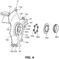
- the transmission case 10 houses therein the transmission mechanism 2 and the starting clutch 4, and includes a cylindrical case body 11 having an opening on the engine side, and a partition wall 12 partitioning the inside of the case body 11 in the axial direction.
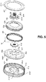
- the outer-side cylindrical portion 41a, the first radial-direction portion 41b, and the first axial-direction portion 41c are formed separately from the second radial-direction portion 41d and the second axial-direction portion 41e.
- a flange portion 41c1 extending from another end portion in the axial direction provided in the first axial-direction portion 41c to the radial-direction inner side and an end portion of the second radial-direction portion 41d on the radial-direction outer side are joined together by welding and integrated.
- the second cylinder portion 12f is located on the radial-direction outer side from the second axial-direction portion 41e of the clutch drum 41 and overlaps with the second axial-direction portion 41e in the axial direction.
- the automatic transmission 1 is connected to the engine without via a torque converter, and thus the starting clutch 4 is configured to be subjected to slip control at the time of starting of the vehicle at the first speed (or the first gear) and the reverse speed (or the reverse gear).
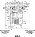
- the lubricating radial-direction oil passage 90a may be orthogonal to the axial direction, extends in the radial direction along the raised wall portion 12b of the partition wall 12, and is connected to the outer peripheral surface of the protrusion 12d.
- the lubricating radial-direction oil passage 90a is provided at a different position from the fastening radial-direction oil passage 80a in the circumferential direction (see FIG. 4 ).
- the lubricating communicating passage 90b is provided at a position corresponding to the lubricating radial-direction oil passage 90a in the circumferential direction, extends from the outer peripheral surface of the protrusion 12d toward the radial-direction inner side, and is open to the inner peripheral surface of the partition wall 12. In this way, the lubricating oil supply passage 90 is formed by the lubricating radial-direction oil passage 90a and the lubricating communicating passage 90b.
- lubricating oil supplied to the inner peripheral surface side of the partition wall 12 via the lubricating oil supply passage 90 is particularly supplied from the radial-direction inner side of the automatic transmission 1 toward the outer side. Further particularly, lubricating oil supplied from a valve body to between the inner peripheral surface of the partition wall 12 and the outer peripheral surface of the input shaft 9 via the lubricating radial-direction oil passage 90a and the lubricating communicating passage 90b is supplied from the second passage S2 and the first passage S1 to a space between the radial-direction portion 44c of the piston 44 and the second radial-direction portion 41d of the clutch drum 41.
- the lubricating oil supplied to the space between the radial-direction portion 44c and the second radial-direction portion 41d passes through the cutout portion 41c2 of the clutch drum 41, is supplied to the inner peripheral surface side of the inner-side cylindrical portion 42a of the clutch hub 42 located on the radial-direction outer side of the cutout portion 41c2, and is supplied from an end portion of the inner-side cylindrical portion 42a on the non-driving source side to between the friction plates 43.
- the lubricating oil supplied to between the friction plates 43 lubricates the friction plates 43 and is supplied to the outer-side cylindrical portion 41a side of the clutch drum 41.
- the lubricating oil supplied to the inner peripheral surface side of the partition wall 12 via the lubricating oil supply passage 90 passes through the through hole 47c of the guide member 47 from the second passage S2 and the first passage S1 as indicated by a dashed arrow of FIG. 3 to lubricate the bearing portion 44e.
- the lubricating oil having been used to lubricate the bearing portion 44e passes through the cutout portion 41c2 of the clutch drum 41 from the radial-direction inner side toward the outer side and is supplied to the clutch hub 42 via the through hole 44g of the cylindrical portion 44b of the piston along a surface of the radial-direction portion 44c of the piston on the non-driving source side.
- the starting clutch 4 includes an oil dam member 41f for facilitating lubrication of the starting clutch 4, and the baffle member 46.
- the oil dam member 41f and the baffle member 46 will be described with reference to FIGs. 3 and 6 to 8 .
- the oil dam member 41f has a function of causing the friction plates 43 to be immersed in oil supplied from the radial-direction inner side toward the outer side, for the lubrication of the starting clutch 4, and has a role as a restricting member which restricts movement of the friction plates 43 in the axial direction at the time of fastening.
- the oil dam member 41f extends to the radial-direction inner side from the baffle member 46 fitted to the inner peripheral side of the clutch hub 42, which will be described later, from the outer-side cylindrical portion 41a toward the inner side.
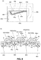
- the tongue piece portion 46e is formed by a slope inclined to the radial-direction inner side from the one axial-direction side toward the other axial-direction side so as to be located on the radial-direction inner side from the land portion 46a1 (body 46a).
- the tongue piece portion 46e is inclined at a predetermined inclination angle with respect to the axial direction.
- An end portion of the flange portion 46f on the radial-direction outer side is located in the vicinity of the body 46a.
- the stopper portion 46h is formed in a disc shape as viewed in the radial direction and is connected to the end portion of the flange portion 46f on the radial-direction outer side in a state of being inclined to the radial-direction inner side from the driving source side toward the non-driving source side along the inclination of the tongue piece portion 46e.
- the stopper portion 46h is formed such that an end portion thereof on the non-driving source side substantially coincides with an outer peripheral surface of the body 46a, and thus an end portion of the stopper portion 46h on the driving source side protrudes to the radial-direction outer side from the outer peripheral surface of the body 46a.
- the end portion of the stopper portion 46h on the driving source side is pressed to the radial-direction inner side by the inner peripheral surface of the inner-side cylindrical portion 42a, so that the stopper portion 46h elastically deforms. Restoring force of the elastically deformed stopper portion 46h suppresses separation of the baffle member 46 from the inner-side cylindrical portion 42a.
- circumferential-direction positions of the land portion 46a1 and the tongue piece portion 46e are set such that the land portion 46a1 corresponds to a tooth top 42a1 of a spline tooth of the clutch hub 42 and the tongue piece portion 46e corresponds to a tooth bottom 42a2 of the spline tooth of the clutch hub 42.
- the oil supplied from the radial-direction inner side toward the outer side is guided to the radial-direction outer side of the inner-side cylindrical portion 42a by the baffle member 46 disposed on the radial-direction inner side of the clutch hub 42.
- the oil can be more effectively supplied to the friction plates 43 disposed on the radial-direction outer side of the clutch hub 42.
- the oil supplied to the groove is supplied from the end portion of the inner-side cylindrical portion 42a on the non-driving source side to the friction plates 43 side, is used to lubricate the friction plates 43 and then is discharged from the radial-direction inner side of the oil dam member 41f.
- the oil dam member 41f extends to the radial-direction inner side from the flange portion 46b of the baffle member 46, and thus a liquid surface of the oil stored in the recess 41g formed by the oil dam member 41f becomes on the radial-direction inner side from the baffle member 46, so that the baffle member 46 can be immersed in the oil. As a result, it becomes easier to obtain the effect of the baffle member 46 to guide the oil to the radial-direction outer side.
- the cylindrical portion 44b of the piston 44 is provided with the through hole 44g, so that the oil supplied from the radial-direction inner side toward the outer side is supplied to the clutch hub 42 located on the outer peripheral side of the cylindrical portion 44b via the through hole 44g of the cylindrical portion 44b of the piston 44. Even when the cylindrical portion 44b of the piston 44 is disposed on the radial-direction inner side of the clutch hub 42, the oil can be supplied to the clutch hub 42.
- the rotational speed sensor S for detecting an input rotational speed of the transmission mechanism 2 is disposed on the radial-direction outer side of the clutch drum 41, so that the gear-shifting control and the like of the transmission can be executed with the input rotational speed of the transmission mechanism 2 detected by the rotational speed sensor S. Furthermore, for example, as compared with a case where the clutch hub 42 is connected to the transmission mechanism 2, the rotational speed sensor S can be disposed with a simple structure.
Landscapes
- Engineering & Computer Science (AREA)
- General Engineering & Computer Science (AREA)
- Mechanical Engineering (AREA)
- Chemical & Material Sciences (AREA)
- Combustion & Propulsion (AREA)
- Transportation (AREA)
- Hydraulic Clutches, Magnetic Clutches, Fluid Clutches, And Fluid Joints (AREA)
- Mechanical Operated Clutches (AREA)
Applications Claiming Priority (1)
| Application Number | Priority Date | Filing Date | Title |
|---|---|---|---|
| JP2020192613A JP7543868B2 (ja) | 2020-11-19 | 2020-11-19 | 自動変速機 |
Publications (1)
| Publication Number | Publication Date |
|---|---|
| EP4001683A1 true EP4001683A1 (fr) | 2022-05-25 |
Family
ID=78413749
Family Applications (1)
| Application Number | Title | Priority Date | Filing Date |
|---|---|---|---|
| EP21204909.2A Withdrawn EP4001683A1 (fr) | 2020-11-19 | 2021-10-27 | Transmission automatique et véhicule |
Country Status (3)
| Country | Link |
|---|---|
| US (1) | US20220154785A1 (fr) |
| EP (1) | EP4001683A1 (fr) |
| JP (1) | JP7543868B2 (fr) |
Citations (5)
| Publication number | Priority date | Publication date | Assignee | Title |
|---|---|---|---|---|
| US20080017469A1 (en) * | 2006-07-24 | 2008-01-24 | Mazda Motor Corporation | Automatic transmission |
| JP2013047571A (ja) | 2012-11-01 | 2013-03-07 | Nsk Warner Kk | 発進クラッチ |
| JP2015059599A (ja) * | 2013-09-18 | 2015-03-30 | アイシン・エィ・ダブリュ株式会社 | 車両用駆動装置 |
| US10487936B2 (en) * | 2016-03-09 | 2019-11-26 | Toyota Jidosha Kabushiki Kaisha | Lubricating system for engagement mechanism |
| JP2020173017A (ja) * | 2019-04-15 | 2020-10-22 | トヨタ自動車株式会社 | 油圧クラッチ |
Family Cites Families (12)
| Publication number | Priority date | Publication date | Assignee | Title |
|---|---|---|---|---|
| SE7414359L (sv) * | 1974-11-15 | 1976-05-17 | Bofors Ab | Sett att kyla en vat lamellkoppling jemte herfor avsedd kopplingslamell |
| JPH04300427A (ja) * | 1990-05-16 | 1992-10-23 | Jatco Corp | 湿式摩擦締結要素 |
| JP3926412B2 (ja) * | 1996-07-17 | 2007-06-06 | 富士重工業株式会社 | 自動変速機の回転数検出装置 |
| JP4221223B2 (ja) * | 2001-03-02 | 2009-02-12 | ツェットエフ ザックス アクチエンゲゼルシャフト | クラッチ装置 |
| JP4006425B2 (ja) | 2004-09-06 | 2007-11-14 | ジヤトコ株式会社 | 自動変速機 |
| JP2008144796A (ja) | 2006-12-07 | 2008-06-26 | Nsk Warner Kk | ユニット型発進クラッチ |
| US9046139B2 (en) * | 2012-12-21 | 2015-06-02 | Caterpillar Inc. | Clutch cooling system |
| US9303696B2 (en) * | 2013-08-23 | 2016-04-05 | American Axle & Manufacturing, Inc. | Optimized outer clutch housing for reduced spin loss, improved oil flow and improved clutch durability |
| DE102014212808A1 (de) * | 2014-07-02 | 2016-01-07 | Schaeffler Technologies AG & Co. KG | Optimierung der Ölverteilung einer nassen/feuchten Mehrscheibenkupplung |
| JP2019127963A (ja) | 2018-01-22 | 2019-08-01 | 株式会社Subaru | 動力伝達装置 |
| JP2019173957A (ja) * | 2018-03-29 | 2019-10-10 | アイシン・エィ・ダブリュ株式会社 | トランスファ |
| DE102019210335A1 (de) * | 2019-07-12 | 2021-01-14 | Zf Friedrichshafen Ag | Schaltelement für ein Getriebe sowie Schaltvorrichtung |
-
2020
- 2020-11-19 JP JP2020192613A patent/JP7543868B2/ja active Active
-
2021
- 2021-10-27 EP EP21204909.2A patent/EP4001683A1/fr not_active Withdrawn
- 2021-11-04 US US17/453,536 patent/US20220154785A1/en not_active Abandoned
Patent Citations (5)
| Publication number | Priority date | Publication date | Assignee | Title |
|---|---|---|---|---|
| US20080017469A1 (en) * | 2006-07-24 | 2008-01-24 | Mazda Motor Corporation | Automatic transmission |
| JP2013047571A (ja) | 2012-11-01 | 2013-03-07 | Nsk Warner Kk | 発進クラッチ |
| JP2015059599A (ja) * | 2013-09-18 | 2015-03-30 | アイシン・エィ・ダブリュ株式会社 | 車両用駆動装置 |
| US10487936B2 (en) * | 2016-03-09 | 2019-11-26 | Toyota Jidosha Kabushiki Kaisha | Lubricating system for engagement mechanism |
| JP2020173017A (ja) * | 2019-04-15 | 2020-10-22 | トヨタ自動車株式会社 | 油圧クラッチ |
Also Published As
| Publication number | Publication date |
|---|---|
| US20220154785A1 (en) | 2022-05-19 |
| JP7543868B2 (ja) | 2024-09-03 |
| JP2022081211A (ja) | 2022-05-31 |
Similar Documents
| Publication | Publication Date | Title |
|---|---|---|
| JP4837000B2 (ja) | 発進クラッチ装置 | |
| JP5680254B2 (ja) | 自動変速機における摩擦締結要素の潤滑構造 | |
| KR100928174B1 (ko) | 내연기관의 시동 토크 전달 기구 | |
| CN110273947B (zh) | 自动变速器 | |
| CN110273946B (zh) | 自动变速器 | |
| JP2006298272A (ja) | トルク伝達装置 | |
| EP2921735B1 (fr) | Embrayage à friction multidisque | |
| US8875859B2 (en) | Hydraulic clutch and transmission device provided with the same | |
| WO2020145290A1 (fr) | Dispositif d'entraînement hybride | |
| EP4001685B1 (fr) | Véhicule comprenant une transmission automatique | |
| CN110273937B (zh) | 自动变速器 | |
| EP3892882B1 (fr) | Structure d'alimentation en huile comprenant un embrayage hydraulique | |
| EP4001683A1 (fr) | Transmission automatique et véhicule | |
| JP2022135638A (ja) | クラッチ装置 | |
| JP7537240B2 (ja) | 自動変速機 | |
| JPS58214059A (ja) | 入力分離型トルクコンバ−タ | |
| JP2019190470A (ja) | 自動変速機 | |
| JP7480684B2 (ja) | 自動変速機 | |
| CN112815073A (zh) | 动力传递装置 | |
| JP5044208B2 (ja) | 発進クラッチ | |
| EP1239190B1 (fr) | Ensemble de transmission | |
| US11614129B2 (en) | Automatic transmission | |
| JP2001323998A (ja) | 変速機 | |
| EP2063144A1 (fr) | Structure de refroidissement d'un appareil d'embrayage pour transmission |
Legal Events
| Date | Code | Title | Description |
|---|---|---|---|
| PUAI | Public reference made under article 153(3) epc to a published international application that has entered the european phase |
Free format text: ORIGINAL CODE: 0009012 |
|
| STAA | Information on the status of an ep patent application or granted ep patent |
Free format text: STATUS: THE APPLICATION HAS BEEN PUBLISHED |
|
| AK | Designated contracting states |
Kind code of ref document: A1 Designated state(s): AL AT BE BG CH CY CZ DE DK EE ES FI FR GB GR HR HU IE IS IT LI LT LU LV MC MK MT NL NO PL PT RO RS SE SI SK SM TR |
|
| STAA | Information on the status of an ep patent application or granted ep patent |
Free format text: STATUS: REQUEST FOR EXAMINATION WAS MADE |
|
| 17P | Request for examination filed |
Effective date: 20221117 |
|
| RBV | Designated contracting states (corrected) |
Designated state(s): AL AT BE BG CH CY CZ DE DK EE ES FI FR GB GR HR HU IE IS IT LI LT LU LV MC MK MT NL NO PL PT RO RS SE SI SK SM TR |
|
| STAA | Information on the status of an ep patent application or granted ep patent |
Free format text: STATUS: THE APPLICATION HAS BEEN WITHDRAWN |
|
| 18W | Application withdrawn |
Effective date: 20230216 |