EP4001003B1 - Faltenbalg für sitzanordnung - Google Patents
Faltenbalg für sitzanordnung Download PDFInfo
- Publication number
- EP4001003B1 EP4001003B1 EP21209832.1A EP21209832A EP4001003B1 EP 4001003 B1 EP4001003 B1 EP 4001003B1 EP 21209832 A EP21209832 A EP 21209832A EP 4001003 B1 EP4001003 B1 EP 4001003B1
- Authority
- EP
- European Patent Office
- Prior art keywords
- skirt
- bellows
- base portion
- seat assembly
- opening
- Prior art date
- Legal status (The legal status is an assumption and is not a legal conclusion. Google has not performed a legal analysis and makes no representation as to the accuracy of the status listed.)
- Active
Links
Images


Classifications
-
- B—PERFORMING OPERATIONS; TRANSPORTING
- B60—VEHICLES IN GENERAL
- B60N—SEATS SPECIALLY ADAPTED FOR VEHICLES; VEHICLE PASSENGER ACCOMMODATION NOT OTHERWISE PROVIDED FOR
- B60N2/00—Seats specially adapted for vehicles; Arrangement or mounting of seats in vehicles
- B60N2/90—Details or parts not otherwise provided for
-
- B—PERFORMING OPERATIONS; TRANSPORTING
- B60—VEHICLES IN GENERAL
- B60N—SEATS SPECIALLY ADAPTED FOR VEHICLES; VEHICLE PASSENGER ACCOMMODATION NOT OTHERWISE PROVIDED FOR
- B60N2/00—Seats specially adapted for vehicles; Arrangement or mounting of seats in vehicles
- B60N2/50—Seat suspension devices
-
- B—PERFORMING OPERATIONS; TRANSPORTING
- B60—VEHICLES IN GENERAL
- B60N—SEATS SPECIALLY ADAPTED FOR VEHICLES; VEHICLE PASSENGER ACCOMMODATION NOT OTHERWISE PROVIDED FOR
- B60N2/00—Seats specially adapted for vehicles; Arrangement or mounting of seats in vehicles
- B60N2/58—Seat coverings
- B60N2/60—Removable protective coverings
-
- F—MECHANICAL ENGINEERING; LIGHTING; HEATING; WEAPONS; BLASTING
- F16—ENGINEERING ELEMENTS AND UNITS; GENERAL MEASURES FOR PRODUCING AND MAINTAINING EFFECTIVE FUNCTIONING OF MACHINES OR INSTALLATIONS; THERMAL INSULATION IN GENERAL
- F16J—PISTONS; CYLINDERS; SEALINGS
- F16J3/00—Diaphragms; Bellows; Bellows pistons
- F16J3/04—Bellows
- F16J3/041—Non-metallic bellows
- F16J3/042—Fastening details
Definitions
- Seat assemblies for vehicles can include a seating portion and a base portion.
- a bellows surrounds the base portion.
- EP-A-2 463 146 discloses a bellows assembly installed within a cab of a vehicle.
- the bellows can generally include a skirt with a break in continuity to provide access to a base of the seat assembly via the break, or to install or remove the skirt from the base without detaching or removing the base portion from the cab or uninstalling the seating portion from the seat assembly.
- the seat assembly can include a seating portion and a base portion with four sides, including a front side, first and second lateral sides, and a rear side.
- the bellows system can include a bellows with a skirt configured to substantially surround a perimeter of the base portion.
- the skirt can exhibit a continuous perimeter extending between first and second free ends of the skirt along the four sides of the base portion of the seat assembly with a break between the first and second free ends of the skirt.
- At least one anchor feature can be configured to releasably engage at least one opening on at least one of the bellows or the base portion to at least one of secure the first and second free ends together at the break or secure the first and second free ends to the base portion, and thereby secure the skirt around the base portion of the seat assembly.
- the at least one anchor feature can be releasable from the at least one opening to provide access to the base portion via the break, or to install or remove the skirt from the base portion, without detaching the base portion from the cab or detaching the seating portion from the seat assembly.
- a skirt can include an accordion portion that is vertically expandable.
- at least one anchor feature can include a first strap and a second strap.
- at least one opening can include a first opening disposed above the accordion portion and a second opening disposed below the accordion portion, and the first strap can be configured to be releasably engaged at the first opening and the second strap can be configured to be releasably engaged at the second opening to secure first and second free ends of the skirt together at a break.
- At least one anchor feature can include a protrusion extending from the base portion to engage the at least one opening
- the seat assembly can include a seating portion and a base portion with four sides, including a front side, first and second lateral sides, and a rear side.
- the bellows assembly can include a bellows with a skirt that is sized to extend vertically to cover at least part of a height of the base portion.
- the skirt can exhibit a continuous perimeter between a first portion and a second portion.
- the skirt can be configured to extend along the four sides of the base portion of the seat assembly with a break between the first and second portions of the skirt.
- the bellows can also include one or more closures configured to at least one of releasably secure the first and second portions of the skirt together at the break or releasably secure the first and second portions of the skirt to the base portion, to secure the bellows to the base portion while the base portion is installed within the cab of the vehicle and while the seating portion is installed on the seat assembly.
- a first portion of a skirt is adjacent to a second portion of the skirt when a bellows is in an installed configuration.
- a skirt can include an accordion portion that is vertically expandable.
- one or more closures can include a first closure and a second closure. The first closure can be arranged above the accordion portion and the second closure arranged below the accordion portion.
- one or more closures can include at least one opening on at least one of (i) one or more of a first or second portions of a skirt, or (ii) a base portion of a seat assembly.
- one or more closures can include at least one anchor feature that engages the at least one opening to releasably secure the first and second portions of the skirt at least one of together or to the base portion.
- At least one opening can be formed on a skirt and can have a reinforced perimeter that is substantially thicker than surrounding skirt material.
- At least one opening can be formed on a skirt and at least one anchor feature can be a strap.
- At least one opening can include an opening on each first and second portions of a skirt that is engageable by a strap.
- strap can be integrally formed with one of a first portion or the second portion of the skirt
- At least one opening can include a keyhole shaped profile.
- At least one anchor feature can be integrally molded with a skirt.
- At least one opening can be formed on a base portion of a seat assembly.
- a gap between first and second portions of a skirt can be defined at a break, with one or more closures securing the first and second portions of the skirt at least one of together at the gap or to a base portion of a seat assembly adjacent to the gap to secure a bellows around the base portion of the seat assembly.
- a bellows can be configured to be secured to a base portion of a seat assembly with a break at a rear side of the base portion.
- At least a portion of top and bottom edges of a skirt can have a reinforced lip that is substantially thicker than surrounding skirt material.
- Some aspects of the disclosure provide a method of installing a bellows onto a seat assembly for a cab of a vehicle.
- the seat assembly can include a seating portion and a base portion.
- the method can include separating first and second free ends of a skirt of the bellows to provide a gap between the first and second free ends.
- the method can also include surrounding the bellows around the base portion while the base portion remains installed within the cab of the vehicle and the seating portion remains installed on the base portion and securing the first and second free ends of the skirt together or to the base portion.
- inserting a strap through an opening on a first free end and an opening on a second free end can secure the first and second free ends of a skirt together.
- inserting an anchor feature on a bellows or a base portion of a seat assembly through an opening on the base portion or the bellows, respectively, can secure first and second free ends of a skirt to the base portion.
- Conventional seating assemblies can include a bellows around a base of a seat assembly.
- Seat bases can include, among other things, suspension systems, adjustment levers, mechanical scissor linkages, dampers, and springs.
- the bellows are traditionally used as a cover for aesthetics or to prevent accidental access to or ingress of objects into suspension systems or other components. These bellows are typically installed onto the base of the seat assembly prior to installation of the seat assembly in a cab of a vehicle, including as a part of a manufacturing process of the seat assembly.
- aspects of the disclosure can provide improved bellows for seat assemblies that can address the pitfalls and shortcomings described above.
- some aspects of the disclosure can provide a bellows that can be installed onto a base of a seat assembly while the seat assembly is installed in a cab of a vehicle.
- a bellows can be installed or uninstalled without removing an entire seat assembly from a cab, without removing a seating portion from a base portion of a seat assembly, or without removing a base portion from a cab.
- installation and removal of a bellows according to some embodiments can be substantially simpler than with conventional designs.
- some embodiments can include a wrap-around bellows that can include a skirt with a split or other break in continuity.
- the break in continuity in the skirt can enable the bellows to be wrapped around a base of the seat while the seat assembly is installed in the vehicle, without necessarily removing any substantial portion of the seat.
- some embodiments can include a closure configured to couple separate portions of the skirt together relative to the break in continuity to secure the bellows around the base of the seat assembly.
- a closure can directly couple free ends of the skirt together.
- a closure can couple free ends of the skirt together indirectly, including by coupling the free ends of the skirt to the seat assembly.
- these or other features can allow for the bellows to be repeatedly and removably installed/uninstalled around a base of a seat assembly without removing the seat assembly, or any substantial portion thereof, from the vehicle. This can also allow for easier access to the base of the seat when servicing or maintenance of the base is required or for a more flexible seat assembly or vehicle manufacturing process.
- the bellows detailed herein could be installed at any point in a manufacturing process, even after a seat has been installed into a vehicle.
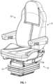
- Fig. 1 illustrates an example of a bellows 10 installed onto a seat assembly 12 according to one embodiment of the disclosure.
- the seat assembly 12 includes a seating portion 14 and a base portion 16.
- the base portion 16 of the seat assembly 12 has four sides, including a front side 18, first and second lateral sides 20, 22, and a rear side 24, which in the illustrated example define a generally rectangular footprint.
- a bellows can be configured according to the principles disclosed herein for use with any variety of other seat assemblies.
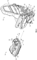
- Fig. 2 illustrates the bellows 10 separated from the seat assembly 12, such as may precede installation of the bellows 10 or may follow from removal of the bellows 10 for further activity on the seat assembly 12.
- the base portion 16 can include, among other things, a suspension system 26 (e.g., for height adjustment system) that can include adjustment levers, mechanical scissor linkages, dampers, springs, or other known components.
- the suspension system 26 can alter the overall height of the base portion 16 or allow the base portion 16 to vary in height dynamically.
- some seat assemblies for use with bellows according to embodiments of the disclosure can vary from the seat assembly 12, including relative to include (or excluded) suspension systems.
- a bellows can substantially surround a perimeter of a base portion, such as by extending fully along the length(s) of one or more sides of a base portion and substantially along the length(s) of the remaining sides of the base portion.
- the bellows 10 includes a skirt 30 configured to substantially surround or enclose a perimeter of the base portion 16 of the seat assembly 12.
- the skirt 30 extends fully along at least three sides of the base portion 16 and extends substantially along at least one additional side of the base portion 16 (e.g., extends fully along the front side 18 and the first and second lateral sides 20, 22, and substantially along the rear side 24 of the base portion).
- a perimeter of a base portion can be defined as the maximum, minimum, average, or footprint perimeter of the base portion at a plane parallel to a floor of a cab of a vehicle.
- the skirt 30 can surround at least 90% of a largest perimeter of the enclosed base portion 16 at a plane parallel to a floor of the cab for an installed seat assembly.
- substantially surround is used herein to describe a structure that surrounds at least 85% of a perimeter or other footprint of a reference structure.
- substantially along or “substantially between” refers an extent of a feature that is at least 85% of a length of a corresponding other feature or a length between corresponding other features.
- a bellows can extend substantially along a height of a base portion. Still referring to Figs. 1-3 , the skirt 30 is configured to substantially cover a height "h" of the base portion 16 (see Fig. 2 ). Further, for example, the skirt 30 substantially covers a vertical height of the base portion 16 at the front side 18, the first and second lateral sides 20, 22, and the rear side 24 of the base portion 16.
- the height "h" of a base portion can be defined as the vertical distance between the bottom of the base portion and the bottom of an associated seat portion, as a vertical distance between an interface between the base portion and a floor of a cab and an interface between the base portion and a seating portion, or a vertical distance between a bottom and a top of a base portion.
- the skirt 30 can cover at least 90% of the height of the base portion 16. In some embodiments, the skirt can cover more or less than 90% of the height of the base portion (e.g., at least: 50%, 60%, 70%, 80%, etc.).
- bellows as disclosed herein can be formed from a variety of materials, including a variety of appropriately durable and flexible materials.
- the bellows 10 can be formed of a rubber or other elastomeric material and be configured to be flexible (e.g., non-rigid) at least at some locations.
- geometry of a bellows can allow for appropriate flexibility even with relatively thick or otherwise rigid materials.
- the bellows 10 includes an accordion portion 32 arranged between a top side 34 and a bottom side 36 of the skirt 30. The accordion portion 32 is coextensive with a perimeter of the bellows 10 as a whole, extending around a perimeter of the skirt 30, including a front side 38, first and second lateral sides 40, 42, and rear side 44 of the skirt 30.
- the accordion portion 32 defines a series of stacked folds (or pleats) 33 of the skirt material that are configured to allow the skirt 30 to freely expand and contract vertically with the base portion 16 while the base portion 16 is undergoing changes in height.
- the suspension system of height adjustment system 26 of the base portion 16 can dynamically vary in height.
- the bellows 10 can vary in height along with the base portion 16 due to the accordion portion 32 of the skirt 30.
- the accordion portion 32 includes three folds 33. In other embodiments, an accordion portion could include more or fewer than three folds depending on a required height adjustability of the bellows, the overall height "h" of the base portion, or other factors.
- some bellows can include breaks along their perimeter, including as may accommodate relatively easy installation or removal of the bellows relative to a seat assembly.
- the skirt 30 includes a first end portion with a first free end 46 and a second end portion with a second free end 48, relative to a perimeter of the skirt 30 that is configured to surround a seat assembly.
- the skirt 30 exhibits a continuous perimeter extending between the first free end 46 and the second free end 48 of the skirt 30 along the four sides of the base portion 16 of the seat assembly 12 (as installed).
- the skirt 30 also includes a break 50 between the first and second free ends 46, 48 that interrupts the continuous perimeter along the break 50.
- the break 50 can be arranged at a rear side 44 of the skirt 30, to correspond to a rear side of a seat assembly.
- a break 50 can be arranged on a front side, first lateral side, or second lateral side of a skirt, or elsewhere (e.g., extending along two sides, arranged at a corner between sides, and so on).
- the break 50 extends vertically fully from the top side 34 to the bottom side 36 of the skirt 30, so that the continuous perimeter of the skirt 30 is broken along the entire height of the skirt 30 and the free ends 46, 48 of the skirt 30 can be moved fully apart from each other to accommodate installation, removal, maintenance, or other operations.
- the first free end 46 is adjacent to the second free end 48, but spaced apart therefrom so that a gap 51 is defined between the first and second free ends 46, 48 with the bellows 10 in an installed or assembled configuration (see Fig. 3 ).
- the gap 51 can be preserved in some installations, with the first and second free ends 46, 48 spaced apart from each other.
- end portions of a skirt may overlap over part or all of a height of a bellows once the bellows is installed. In such an embodiment, a gap may still exist relative to a distance between free ends of a skirt, although the end portions may overlap.
- free ends may touch after installation, such that no gap between the free ends exists, although the skirt may still exhibit a break in continuity relative to the break in material continuity between the free ends (e.g., the skirt exhibiting a vertical split line through the skirt material).
- the bellows 10 can be configured to be installed onto the base portion 16 of the seat assembly 12 without detaching the base portion 16 from the cab of a vehicle (e.g., while the base portion remains coupled to a floor of a vehicle or cab) or detaching the seating portion 14 from the seat assembly 12 (e.g., while the seating portion 14 remains coupled to the base portion 16).
- the first and second free ends 46, 48 of the skirt 30 can be separated at the break 50 such that deformation of the bellows 10 causes the gap 51 to be enlarged (or formed, as appropriate) between the first and second free ends 46, 48 (as illustrated by arrows 52).
- the gap 51 formed between the first and second free ends 46, 48 can be sufficiently large to pass along opposing sides of the seat assembly 12 and thereby to allow the bellows 10 to be installed onto the base portion 16 of the seat assembly 12.
- the gap 51 can be enlarged for the illustrated example to be equal to, or wider than, a width "w" of the base portion 16.
- the gap 51 formed between the free ends of the skirt could be sufficiently enlarged to allow the bellows 10 to be installed onto the base portion 16 of the seat assembly 12 from a lateral side (e.g., lateral sides 40, 42) of the base portion 16.
- the bellows 10 can then be wrapped around the base portion 16, to substantially surround the base portion 16, while the base portion 16 remains installed within the cab of the vehicle and the seating portion 14 remains installed on the base portion 16.
- the bellows 10 can include one or more closures 53, 153 configured to releasably secure the first and second free ends 46, 48 of the skirt 30 together at the break 50, and/or to releasably secure the first and second free ends 46, 48 of the skirt 30 to the base portion 16, to secure the bellows 10 around the base portion 16 of the seat assembly 12.
- closures can include anchor features and anchor points, in which the anchor features and anchor points can be embodied in various forms.
- anchor points can be configured as openings, hook and loop fasteners, buttons, or snaps, among others.
- the one or more closures 53, 153 include a plurality of anchor points configured as openings 54 and a corresponding plurality of anchor features 56, 156.
- the plurality of anchor features can be configured as flexible connectors or features on the base portion 16 (e.g., protrusions extending therefrom) to engage the anchor points or openings 54 (or other features) of the skirt 30.
- anchor features can include only features on a base that are configured to engage openings or other features on a skirt.
- anchor features can include only features that are on, or configured to only engage, a skirt.
- the embodiment illustrated in Fig. 3 may sometimes include the anchor features 56 but not the anchor features 156 (or vice versa), may include variations on the anchor features 56 that are configured to also (or alternatively) engage the base portion 16 of the seat assembly 12, or may include variations on the anchor features 156 that are configured to engage the openings 54 or other features on the skirt 30 in other ways.
- the anchor features 56, 156 can be configured to collectively or individually releasably engage a corresponding set of the openings 54 to secure the skirt 30 around the seat assembly 12.
- the openings 54 on the skirt 30 are arranged adjacent to the first or second free ends 46, 48.
- Each of the anchor features 56 can be received in a corresponding set of the openings 54 to secure the first and second free ends 46, 48 of the skirt 30 together at the break 50 and thereby secure the skirt 30 around the base portion 16 of the seat assembly 12.
- the anchor features 56 are configured as flexible connectors.
- each of the anchor features 156 (shown in dashed lines in Fig.
- anchor features 156 are configured as protrusions extending from the base portion 16, although other configurations are also possible.
- anchor features formed as protrusions can be in the form of a tab, bracket, or a hook.
- some anchor features can be releasable from one or more corresponding openings to provide access to an interior area of a bellows (e.g., to a base portion of a seat assembly), or to install or remove the bellows from a seat assembly, including as generally described above (e.g., without detaching a base portion of a seat assembly from a cab of a vehicle or detaching a seating portion from a larger seat assembly).
- the skirt 30 includes top openings 54A, 54B disposed above the accordion portion 32 and a bottom openings 54C, 54D disposed below the accordion portion 32.
- the top and bottom openings 54A-54D are adjacent to the break 50.
- the anchor feature 56 includes a first strap 62 and a second strap 64.
- the first strap 62 can be configured to releasably engage one or more of the openings in the top openings 54A, 54B and the second strap 64 can be configured to releasably engage one or more of the openings in the bottom openings 54C, 54D to secure the first and second free ends 46, 48 together at the break 50.
- the first and second straps 62, 64 can include a hook and loop fastener on one or more sides of the first and second straps 62, 64, or can use other known devices (e.g., ratcheting mechanisms) to secure a strap against unwanted movement.
- the first and second straps 62, 64 can be made of fabric, rubber, metal, or any combination thereof.
- the anchor features 56 are in the form of straps, however other fastening features are also possible.
- other anchor features can be in the form of a clasp or a clamp or a protrusion of various types (e.g., similar to the protrusions 156 on the base portion 16).
- some straps can be integrally formed with other portions of a bellows.
- closures apart from parts of a bellows that substantially deform during operation of an associated seat it may be useful to dispose closures apart from parts of a bellows that substantially deform during operation of an associated seat.
- the location of the closures 53, including the top and bottom openings 54A-54D and the first and second straps 62, 64, being above and below the accordion portion 32 can help to ensure that the closures 53 are not overly stressed or loosened by expansion or contraction of the accordion portion 32 as the base portion 16 varies in height.
- the location of the closures 53 being above/below the accordion portion 32 can also locate the closures 53 near other anchor points for the bellows 10 (e.g., fastening or coupling points between the skirt 30 and the base portion 16, described in detail below), such as may facilitate easier installation or removal of the bellows 10. Further, the illustrated location may help to ensure that the closures 53 remain accessible regardless of the state of the accordion portion 32 (e.g., regardless of the current height adjustment of the seat assembly 12).
- the bellows 10 includes a plurality of openings 66 below the accordion portion 32 adjacent to a bottom edge 68 of the skirt 30.
- the first lateral side 40 includes two openings 66 and the second lateral side 42 includes two similar openings (not shown).
- the plurality of openings 66 can be configured to receive fasteners 70 (see Fig. 3 ) to secure the bottom edge 68 of the skirt 30 to the base portion 16.
- the bellows 10 can also include a plurality of slots 72 or other openings above the accordion portion 32 adjacent to a top edge 74 of the skirt 30.
- the front side 38 includes two slots 72.
- the plurality of slots 72 can be configured to clip in or hook on to a corresponding bracket or extension of the base portion 16 to secure the top edge 74 of the skirt 30 to the base portion 16.
- the bellows 10 also includes a set of arcuate openings 76 that can be configured to movably receive extensions of the base portion 16 (see Fig. 3 ).
- the arcuate openings 76 can be arranged directly opposite each other on the first and second lateral sides 40, 42 of the skirt 30.
- the skirt 30 can include a plurality of other features such as cutouts, bulges, and openings to allow the bellows 10 to conform to or make clearance for various protrusions, fasteners, and mechanical linkages that are coupled to, or otherwise form a part of, the base portion 16.
- a top side of the skirt 30 includes cap portions 78.
- the cap portions 78 extend inwardly towards the base portion 16, with the bellows 10 installed, such that the cap portions 78 overlap with at least a portion of the top side of the base portion 16. In some cases, for example, this can help to secure the top side of the skirt 30 to the base portion 16.
- the top side of the skirt 30 can define an opening 80 that is substantially rectangular in shape.
- the rectangular shape of the opening 80 can define four corners, and the cap portions of the skirt 30 can extend inwardly from the four corners of the opening 80 to engage with the base portion.
- differently configured openings are possible, including openings without cap portions or with differently configured cap portions.
- portions of the bellows 10 include a reinforcing lip, extending in some cases along a perimeter of the bellows 10 or a feature thereof.
- the reinforced lips along portions of the bellows 10 can be configured to add strength and durability to areas of the skirt 30.
- at least a portion of top and bottom edges 74, 68 of the skirt 30 have a respective reinforced lip 82 that is substantially thicker than the surrounding skirt material.
- the reinforced lip 82 can be about 10% to 200% thicker than the surrounding skirt material (e.g., a 10% to 200% increase in cross-sectional thickness, see Fig. 8 ).
- the reinforced lip 82 can be about 20% to 100% thicker than the surrounding skirt material.
- the reinforced lips 82 extend around the entirety top edge 74 (e.g., upper perimeter) of the skirt 30 and also around the entirety of the bottom edge 68 (e.g., lower perimeter) of the skirt 30. Further, the top and bottom reinforced lips 82 extend along a portion of the edges of the first and second free ends 46, 48 of the skirt 30 along the break 50. However, in the illustrated embodiment, the reinforced lips 82 do not extend along the folds 33 of the accordion portion 32 at the break 50. The lack of reinforcing lip at the break 50 along the accordion portion 32 can allow the accordion portion 32 to flex and bend evenly and uniformly.
- each of the openings 54 include a reinforced perimeter 84.
- the reinforced perimeter 84 can be substantially thicker than the surrounding skirt material.
- the reinforced perimeter 84 can be about 10% to 200% thicker than the surrounding skirt material (e.g., a 10% to 200% increase in cross-sectional thickness, see Fig. 9 ).
- the reinforced perimeter 84 can be about 20% to 100% thicker than the surrounding skirt material.
- the reinforced lips and perimeters 82, 84 are integrally formed with the skirt 30 (i.e., formed of the same material as the skirt 30).
- the reinforced lips or perimeters 82, 84 can be in the form of a metal, plastic, or composite component (e.g., a grommet fitted into the openings 54 or onto an edge of the skirt 30).
- the reinforced lips or perimeters 82, 84 can include materials that are over-molded or insert-molded into the bellows 10 during manufacturing.
- a wire (not shown) could be insert molded into the bellows 10 during manufacturing such that the wire is surrounded by skirt material, thereby causing the increase in cross-sectional thickness of the skirt in the region of the reinforced lips or perimeters 82, 84.
- the reinforced lips or perimeters 82, 84 can be a separate part to be inserted, fitted, or installed after molding the skirt 30.
- first and second straps 62, 64 are illustrated in an installed configuration ( Figs. 10A and 10C ) and an unfurled configuration ( Fig. 10B ). Note that only one strap is shown for ease of illustration and the following discussion will be made with respect to the first strap 62. It is to be understood that the following discussion is also applicable to the second strap 64.
- the first strap 62 includes a strap portion 86 and an eyelet portion 88 at a distal end of the strap portion 86.
- the eyelet portion 88 includes a slot 90 configured to receive the strap portion 86 therethrough.
- the first strap 62 can also include a hook and loop fastener on one or more of the surfaces of the strap (e.g., the strap portion 86 and the eyelet portion 88).
- the first strap can be manufactured from a hook and loop fastener material such that a first side 92 of the first strap 62 can be the hook side and the second side (not shown) can be the loop side. In that way, when the first strap 62 comes into contact with itself due to an overlapping configuration, the strap can be maintained in a particular shape or orientation.
- first and second straps 62, 64 can releasably engage the top and bottom openings 54A-54D to secure the first and second free ends 46, 48 of the skirt 30 together at the break 50.
- the first strap 62 can be inserted through opening 54A of the top openings 54A, 54B on the first free end 46 of the skirt 30.
- the first strap 62 can then be inserted through the slot 90 in the eyelet portion 88 to form a first loop 96.
- a distal end of the first strap 62 opposite the eyelet portion 88 can then be pulled to tighten the first loop 96 around the first free end 46 of the skirt 30 at the first opening 94, thereby coupling the first strap 92 to the first free end 46 of the skirt 30.
- the first strap 62 can then be inserted through the gap 51 and into opening 54B of the top openings 54A, 54B on the second free end 48 of the skirt 30.
- the first strap 62 can then be routed back towards the first opening 94, thereby forming a second loop 100.
- the remainder of the length of the first strap 62 can be wrapped around itself such that the first loop 96 and the second loop 100 become coupled together.
- the particular arrangement of overlapping portions of a strap with itself can allow for a secure coupling of the first and second free ends of a skirt.
- the overlapping can increase the contact area between hook side and loop side surfaces, thereby increasing a strength of the coupling.
- the strap could be a rubberized material that uses friction to maintain the overlapped or coiled shape of the strap.
- the overlapping can increase the total area of the strap being in contact with itself, thereby allowing for a larger area for friction to act upon.
- the strap can be configured to exhibit persistent plastic deformation or can have one or more magnets and ferromagnetic materials embedded or included within the strap such that the magnets can allow the strap to be coupled with itself and remain in the overlapped configuration shown in Fig. 10C .
- one or more of the anchor features 56, 156 can allow a user or technician to gain access to the base portion 16 without detaching the base portion 16 from the cab of a vehicle (i.e., while the base portion is coupled to a floor of a vehicle or cab) or detaching the seating portion 14 from the seat assembly 12 (i.e., while the seating portion 14 is coupled to the base portion 16).
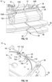
- Figs. 11-14 illustrate various other embodiments of a bellows 10. Aspects of the bellows 10 illustrated in Figs. 11-14 that are substantially similar to the embodiment illustrated in Figs. 1-10C will be labeled with like reference numerals. It is to be understood that elements labeled with like reference numerals, unless otherwise stated in the following description or illustrated in the figures, have a similar functionality to those elements described above with respect to Figs. 1-10C .
- the bellows 10 includes an accordion portion 32 arranged between a top side 34 and a bottom side 36 of a skirt 30.
- the skirt 30 includes a first free end 46 and a second free end 48 with a break 50 therebetween.
- the bellows 10 can also include one or more closures 53 configured to releasably secure the first and second free ends 46, 48 of the skirt 30 together at the break 50.
- the one or more closures 53 include a plurality of openings 54 arranged adjacent to the free ends 46, 48 and plurality of corresponding anchor features 56 configured as integrally formed connectors that can releasably engage the openings 54.
- a first strap 62 and a second strap 64 extend from the first free end 46 of the skirt 30.
- the first and second straps 62, 64 are integrally formed with the first free end 46 and extend from the first free end 46 towards the second free end 48 at the break 50, although other configurations are possible (e.g., with one or more straps extending from each free end).
- the straps 62, 64 can include a reinforcing lip.
- the second free end 48 of the skirt 30 includes a first set of openings 104 disposed above the accordion portion 32 and the first strap 62 includes a plurality of first strap openings 102.
- the first set of openings 104 can be aligned with the first strap openings 102 and anchor features configured as fasteners (e.g., pins) can be received therethrough to hold the bellows 10 in place.
- the second strap 64 includes a plurality of second strap openings 108 configured as keyhole openings, and one or more protrusions 106 are provided adjacent the second free end 48 of the skirt 30 below the accordion portion 32.
- the second strap openings 108 can receive the protrusions 106 to couple the first and second free ends 46, 48 of the skirt 30 together at the break 50.
- a third embodiment of a bellows 10 is illustrated.
- another example of a closure 153 is provided.
- anchor features 156A, 156B formed as protrusions extend from a portion of the base portion 16 of the seat assembly.
- the anchor features 156A, 156B can extend from the base portion 16 of the seat assembly to extend into top openings 54A, 54B of the skirt 30.
- the anchor features 156A, 156B are in the form of planar tabs.
- other configurations are also within the scope of this application.
- some protrusions can include a bracket or a hook that are coupled to the base portion of a seat assembly and are configured to engage openings or other features on a skirt.
- openings 54A, 54B are arranged near a top side 34 of the skirt 30, above the accordion portion 32, and adjacent to the break 50. Accordingly, the first and second free ends 46, 48 of the skirt 30 can be secured to the base portion 16 near the break 50.
- only one closure 153 is illustrated, with the two anchor features 156A, 156B on opposing sides of the break 50.
- an additional closure e.g., similarly configured to the closure 153 may be provided below the accordion portion 32.
- a fourth embodiment of a bellows 10 is illustrated.
- another example of a closure 153 is provided.
- anchor features 156 can extend from the skirt 30 to engage openings 154 within the base portion 16 of the seat assembly.
- the anchor features 156 are in the form of protrusions 110 provided adjacent the first and second free ends 46, 48 of the skirt 30 above the accordion portion 32 and the openings 154 are in the form of similarly positioned keyhole openings 112, although other configurations are also possible.
- the openings 154 can receive the protrusions 110 to couple the first and second free ends 46, 48 of the skirt 30 to the base portion 16 of the seat assembly.
- the openings 154 are arranged near a top side of the base portion 16 and adjacent to the break 50 within the skirt 30. In that way, the first and second free ends 46, 48 of the skirt 30 can be secured to the base portion 16 near the break 50.
- only one closure 153 is illustrated, however, it is to be understood that an additional closure may be provided below the accordion portion 32.
- closures described herein can include anchor features and anchor points that can be embodied in various forms.
- free ends of the skirt (or portions thereof) can include complementary features that can engage with each other to secure the free ends of the skirt to either each other or a base portion of a seat assembly.
- These complementary features can include snaps with complementary male and female portions that can be arranged on first and second ends of a skirt to engage with each other or with complementary male and female portions arranged on a base portion of a seat assembly.
- hook and loop fasteners can be employed on ends of a skirt, integrally molded within the skirt, attached to a base portion of a seat, or otherwise arranged.
- buttons could be used, which could engage corresponding openings.
Landscapes
- Engineering & Computer Science (AREA)
- Mechanical Engineering (AREA)
- Aviation & Aerospace Engineering (AREA)
- Transportation (AREA)
- General Engineering & Computer Science (AREA)
- Seats For Vehicles (AREA)
Claims (15)
- Faltenbalganordnung für eine Sitzanordnung (12) für eine Fahrerkabine eines Fahrzeugs, wobei die Sitzanordnung (12) einen Sitzabschnitt (14) und einen Basisabschnitt (16) mit vier Seiten, einschließlich einer Vorderseite (18), einer ersten und zweiten lateralen Seite (20, 22) und einer Rückseite (24), umfasst, wobei die Faltenbalganordnung Folgendes umfasst:einen Faltenbalg (10) mit einer Schürze (30), der dazu dimensioniert ist, sich vertikal zu erstrecken, um zumindest einen Teil einer Höhe des Basisabschnitts (16) zu bedecken, wobei die Schürze (30) einen durchgehenden Umfang zwischen einem ersten Abschnitt und einem zweiten Abschnitt aufweist,dadurch gekennzeichnet, dassdie Schürze (30) dazu ausgelegt ist, sich entlang der vier Seiten (18, 20, 22, 24) des Basisabschnitts (16) der Sitzanordnung (12) zu erstrecken, mit einer Unterbrechung (50) zwischen dem ersten und zweiten Abschnitt der Schürze (30); und durcheinen oder mehrere Verschlüsse (53; 153), die dazu ausgelegt sind, den ersten und zweiten Abschnitt der Schürze (30) zusammen lösbar an der Unterbrechung (50) zu befestigen und/oder den ersten und zweiten Abschnitt der Schürze (30) lösbar am Basisabschnitt (16) zu befestigen, um den Faltenbalg (10) am Basisabschnitt (16) zu befestigen, während der Basisabschnitt (16) innerhalb der Fahrerkabine des Fahrzeugs eingebaut ist und während der Sitzabschnitt (14) an der Sitzanordnung (12) eingebaut ist.
- Faltenbalganordnung nach Anspruch 1, wobei der erste Abschnitt an den zweiten Abschnitt angrenzt, wenn sich der Faltenbalg (10) in einer eingebauten Konfiguration befindet;
optional oder vorzugsweise wobei der erste Abschnitt ein erstes freies Ende der Schürze ist und der zweite Abschnitt ein zweites freies Ende der Schürze ist. - Faltenbalganordnung nach einem der Ansprüche 1 oder 2, wobei die Schürze (30) einen Akkordeonabschnitt (32) umfasst, der vertikal ausdehnbar ist;wobei der eine oder die mehreren Verschlüsse (53; 153) einen ersten Verschluss und einen zweiten Verschluss umfassen, wobei der erste Verschluss über dem Akkordeonabschnitt (32) angeordnet ist und der zweite Verschluss unter dem Akkordeonabschnitt (32) angeordnet ist;optional oder vorzugsweise wobei der erste Verschluss einen Gurt (62) und eine erste Öffnung (54A; 102) umfasst und der zweite Verschluss einen zweiten Gurt (64) und eine zweite Öffnung (54C; 108) umfasst, und wobei der erste Gurt (62) dazu ausgelegt ist, lösbar an der ersten Öffnung (54A; 102) einzugreifen, und der zweite Gurt (64) dazu ausgelegt ist, lösbar an der zweiten Öffnung (54C; 108) einzugreifen, um den ersten und zweiten Abschnitt der Schürze (30) zusammen an der Unterbrechung (50) zu befestigen.
- Faltenbalganordnung nach Anspruch 1, wobei der eine oder die mehreren Verschlüsse (53; 153) Folgendes umfassen:mindestens eine Öffnung (54; 154) (i) an einem oder mehreren des ersten oder zweiten Abschnitts der Schürze (30) und/oder (ii) am Basisabschnitt (16) der Sitzanordnung (12) undmindestens ein Verankerungsmerkmal (56; 156), das in die mindestens eine Öffnung (54; 154) eingreift, um den ersten und zweiten Abschnitt der Schürze (30) aneinander und/oder am Basisabschnitt (16) lösbar zu befestigen;optional oder vorzugsweise wobei das mindestens eine Verankerungsmerkmal (56; 156) von der mindestens einen Öffnung (54; 154) lösbar ist, um über die Unterbrechung (50) einen Zugang zum Basisabschnitt (16) vorzusehen, oder um die Schürze (30) am Basisabschnitt (16) zu montieren oder zu demontieren, ohne den Basisabschnitt (16) von der Fahrerkabine zu lösen oder den Sitzabschnitt (14) von der Sitzanordnung (12) zu lösen.
- Faltenbalganordnung nach Anspruch 4, wobei die mindestens eine Öffnung (54A) an der Schürze (30) ausgebildet ist und einen verstärkten Rand (84) aufweist, der erheblich dicker ist als das umgebende Schürzenmaterial;
optional oder vorzugsweise wobei das mindestens eine Verankerungsmerkmal (156) einen Vorsprung (156A) umfasst, der sich von dem Basisabschnitt (16) erstreckt, um in die mindestens eine Öffnung (54A) einzugreifen. - Faltenbalganordnung nach Anspruch 4, wobei die mindestens eine Öffnung (54) an der Schürze (30) ausgebildet ist und das mindestens eine Verankerungsmerkmal (56) ein Gurt (64) ist;
optional oder vorzugsweise wobei der Gurt (64) mit dem ersten Abschnitt oder dem zweiten Abschnitt der Schürze (30) einstückig ausgebildet ist und die mindestens eine Öffnung (54) ein schlüssellochförmiges Profil aufweist. - Faltenbalganordnung nach Anspruch 6, wobei die mindestens eine Öffnung (54) jeweils eine Öffnung (54C, 54D) an dem ersten und zweiten Abschnitt der Schürze (30) umfasst, in die der Gurt (64) eingreifen kann.
- Faltenbalganordnung nach Anspruch 4, wobei das mindestens eine Verankerungsmerkmal (56; 156) mit der Schürze (30) einstückig geformt ist.
- Faltenbalganordnung nach Anspruch 8, wobei die mindestens eine Öffnung (154) am Basisabschnitt (16) der Sitzanordnung (12) ausgebildet ist.
- Faltenbalganordnung nach Anspruch 1, wobei ein Spalt (51) zwischen dem ersten und zweiten Abschnitt der Schürze (30) an der Unterbrechung (50) definiert ist, wobei der eine oder die mehreren Verschlüsse (53; 153) den ersten und zweiten Abschnitt der Schürze (30) aneinander am Spalt (50) und/oder am an den Spalt (50) angrenzenden Basisabschnitt (16) befestigen, um den Faltenbalg (10) um dem Basisabschnitt (16) der Sitzanordnung (12) zu befestigen.
- Faltenbalganordnung nach einem der vorstehenden Ansprüche, wobei der Faltenbalg (10) dazu ausgelegt ist, mit der Unterbrechung (50) an der Rückseite (24) des Basisabschnitts (16) am Basisabschnitt (16) der Sitzanordnung (12) befestigt zu sein.
- Faltenbalganordnung nach einem der vorstehenden Ansprüche, wobei zumindest ein Abschnitt der oberen und unteren Kante (74, 68) der Schürze (30) eine verstärkte Lippe (82) aufweisen, der erheblich dicker ist als das umgebende Schürzenmaterial.
- Verfahren zum Einbau eines Faltenbalgs (10) einer Faltenbalganordnung nach Anspruch 1 an einer Sitzanordnung (12) für eine Fahrerkabine eines Fahrzeugs, wobei die Sitzanordnung (12) einen Sitzabschnitt (14) und einen Basisabschnitt (16) umfasst, wobei das Verfahren Folgendes umfasst:Trennen eines ersten und zweiten freien Endes (46, 48) einer Schürze (30) des Faltenbalgs (10) an einer Unterbrechung (50) der Schürze (30), um einen Spalt (51) zwischen dem ersten und zweiten freien Ende (46, 48) vorzusehen;Ummanteln des Faltenbalgs (10) um den Basisabschnitt (16), während der Basisabschnitt (16) innerhalb der Fahrerkabine des Fahrzeugs eingebaut bleibt und der Sitzabschnitt (14) am Basisabschnitt (16) eingebaut bleibt; undBefestigen des ersten und zweiten freien Endes (46, 48) der Schürze (30) aneinander oder am Basisabschnitt (16).
- Verfahren nach Anspruch 13, ferner umfassend das Einführen eines Gurtes (62) durch eine Öffnung (54A) am ersten freien Ende (46) und eine Öffnung (54B) am zweiten freien Ende (48), um das erste und zweite freie Ende (46, 48) der Schürze (30) aneinander zu befestigen.
- Verfahren nach Anspruch 13, ferner umfassend das Einführen eines Verankerungsmerkmals (56; 156) am Faltenbalg (10) oder am Basisabschnitt (16) durch eine Öffnung (54; 154) am Basisabschnitt (16) bzw. am Faltenbalg (10), um das erste und zweite freie Ende (46, 48) der Schürze (30) am Basisabschnitt (16) zu befestigen.
Applications Claiming Priority (1)
| Application Number | Priority Date | Filing Date | Title |
|---|---|---|---|
| US17/101,747 US11932148B2 (en) | 2020-11-23 | 2020-11-23 | Bellows for seat assembly |
Publications (2)
| Publication Number | Publication Date |
|---|---|
| EP4001003A1 EP4001003A1 (de) | 2022-05-25 |
| EP4001003B1 true EP4001003B1 (de) | 2023-04-12 |
Family
ID=78770432
Family Applications (1)
| Application Number | Title | Priority Date | Filing Date |
|---|---|---|---|
| EP21209832.1A Active EP4001003B1 (de) | 2020-11-23 | 2021-11-23 | Faltenbalg für sitzanordnung |
Country Status (4)
| Country | Link |
|---|---|
| US (1) | US11932148B2 (de) |
| EP (1) | EP4001003B1 (de) |
| CN (1) | CN114523891A (de) |
| AU (1) | AU2021273547A1 (de) |
Families Citing this family (2)
| Publication number | Priority date | Publication date | Assignee | Title |
|---|---|---|---|---|
| JP7795429B2 (ja) * | 2022-07-14 | 2026-01-07 | 日本発條株式会社 | 車両用シートの下部構造 |
| US20240216195A1 (en) * | 2022-12-28 | 2024-07-04 | Roger Joseph Voorhis, Jr. | Personal Lift Chair |
Family Cites Families (32)
| Publication number | Priority date | Publication date | Assignee | Title |
|---|---|---|---|---|
| US2025635A (en) | 1932-01-15 | 1935-12-24 | Charles C Bishoff | Protector for drive shaft joints |
| DE3228834A1 (de) * | 1982-08-02 | 1984-02-02 | Siemens Ag | Hubvorrichtung fuer insbesondere einen zahnaerztlichen patientenstuhl |
| DE3228853A1 (de) * | 1982-08-02 | 1984-02-09 | Siemens AG, 1000 Berlin und 8000 München | Zahnaertzlicher patientenstuhl |
| US4448382A (en) * | 1982-08-16 | 1984-05-15 | Smith Investment Company | Power operated chair lift mechanism |
| US4598946A (en) * | 1985-01-02 | 1986-07-08 | Collier-Kenworth Company | Rocking infant seat |
| DE3517505A1 (de) * | 1985-05-15 | 1986-11-20 | Grammer Sitzsysteme GmbH, 8450 Amberg | Abgefederter fahrzeugsitz |
| US4778216A (en) * | 1987-04-20 | 1988-10-18 | Jss Scientific Corporation | Lightweight transportable dental chair |
| GB9209787D0 (en) * | 1992-05-06 | 1992-06-17 | Robert Pringle Engineers Ltd | Jacks and dentists or other chairs |
| JPH10184913A (ja) | 1996-12-25 | 1998-07-14 | Nok Corp | ブーツ |
| US7219960B1 (en) * | 1998-06-12 | 2007-05-22 | Hajianpour Mohammed A | Lifting chair with moving arms |
| DE69934800T2 (de) | 1998-08-04 | 2007-10-11 | Nok Corp. | Geteilte dichtungsmanschette und verbindungsmethode, schweissmittel und heizkörper dafür |
| CA2539336C (en) | 2003-10-20 | 2011-07-05 | Tokue Inc. | Boot for universal shaft coupling |
| US7219961B2 (en) * | 2005-04-06 | 2007-05-22 | Cnh America Llc | Pivoting seat |
| US8864145B2 (en) * | 2005-05-13 | 2014-10-21 | Grammer Ag | Device and method for suspension of a vehicle seat by means of additional volumes |
| DE102005023088B3 (de) * | 2005-05-13 | 2006-06-22 | Grammer Ag | Vorrichtung und Verfahren zur Federung eines Fahrzeugsitzes mittels Zusatzvolumina |
| ITTO20060312A1 (it) | 2006-04-27 | 2007-10-28 | Webasto Product Italy S P A | Sedile per macchine per movimentazione terra o similari |
| DE102007059509B3 (de) * | 2007-12-07 | 2008-11-06 | Keiper Gmbh & Co.Kg | Faltenbalg für einen Fahrzeugsitz |
| JP5236799B2 (ja) * | 2009-03-04 | 2013-07-17 | 株式会社小松製作所 | 建設機械のオペレータ用シート構造体 |
| US8100457B2 (en) * | 2009-03-24 | 2012-01-24 | Daimler Ag | Seat system for the interior of a motor vehicle |
| JP5065542B2 (ja) * | 2010-03-23 | 2012-11-07 | 株式会社小松製作所 | 建設機械用シートベルトおよびこれを備えた建設機械 |
| FR2966545B1 (fr) | 2010-10-20 | 2013-07-19 | Groupe Contino | Soufflet de protection de bas de siege |
| DE102010053752A1 (de) * | 2010-12-08 | 2012-06-14 | Grammer Aktiengesellschaft | Fahrzeugschwingungsvorrichtung für Fahrzeugsitze oder Fahrzeugkabinen |
| WO2014096894A1 (en) * | 2012-12-17 | 2014-06-26 | Renault Trucks | Seat belt arrangement for a suspension seat and vehicle equipped with such an arrangement |
| DE102012112557B4 (de) * | 2012-12-18 | 2018-07-05 | Grammer Ag | Fahrzeugsitz, insbesondere für Nutzfahrzeuge, mit einem Sitzteil und einer Rückenlehne und gemeinsam nutzbaren Funktionen |
| DE102013110370B4 (de) * | 2013-06-04 | 2014-12-11 | Grammer Ag | Fahrzeugsitz |
| US9321375B2 (en) * | 2013-06-26 | 2016-04-26 | Sears Manufacturing Co. | Vehicle seat apparatus having suspension with independent armrest adjustment |
| US20150137567A1 (en) * | 2013-11-20 | 2015-05-21 | Donna Marie Antoinette Smith | Lifting and lowering chair |
| US20150352987A1 (en) * | 2015-08-15 | 2015-12-10 | Caterpillar Inc. | Control system for a seat |
| US20160355111A1 (en) * | 2015-08-17 | 2016-12-08 | Caterpillar Inc. | Control system for a seat |
| US20170008430A1 (en) * | 2016-09-21 | 2017-01-12 | Caterpillar Inc. | Operator seat adjustment system |
| EP3552873B1 (de) * | 2018-04-13 | 2020-08-05 | Grammer AG | Fahrzeugsitz mit gemeinsam verstellbaren schaltkonsolen |
| US10800298B2 (en) | 2018-08-28 | 2020-10-13 | Deere & Company | Seat suspension system with horizontal movement and dampening |
-
2020
- 2020-11-23 US US17/101,747 patent/US11932148B2/en active Active
-
2021
- 2021-11-23 AU AU2021273547A patent/AU2021273547A1/en not_active Abandoned
- 2021-11-23 EP EP21209832.1A patent/EP4001003B1/de active Active
- 2021-11-23 CN CN202111390662.0A patent/CN114523891A/zh active Pending
Also Published As
| Publication number | Publication date |
|---|---|
| CN114523891A (zh) | 2022-05-24 |
| US20220161702A1 (en) | 2022-05-26 |
| EP4001003A1 (de) | 2022-05-25 |
| US11932148B2 (en) | 2024-03-19 |
| AU2021273547A1 (en) | 2022-06-09 |
Similar Documents
| Publication | Publication Date | Title |
|---|---|---|
| EP4001003B1 (de) | Faltenbalg für sitzanordnung | |
| EP2471416B1 (de) | Klammer, verbindungsklammer und sitzabdeckungsmontagestruktur | |
| EP2705981B1 (de) | Fahrzeugsitz und sitzrückwand | |
| EP2781806B1 (de) | Abdeckstopfen | |
| EP0952935B1 (de) | Fussmatte mit angeformter tür | |
| JP5519806B2 (ja) | 統合されたプラスチック部及びファスナー | |
| US20100186197A1 (en) | Harness clip structure | |
| US10396489B2 (en) | Grommet | |
| EP1094585B1 (de) | Kabelführungskette | |
| US20080169260A1 (en) | Filler Neck Closure | |
| WO2008070285A1 (en) | Retention clip | |
| AU2008284731A1 (en) | Clip and support member | |
| WO2019111234A1 (en) | Pre-loaded two-lobe spring twist-on rearview mounting assembly | |
| US11679704B1 (en) | Device and method for setting or removing seat trim | |
| CN103004043A (zh) | 护线环 | |
| CN113492985A (zh) | 装饰罩拉带保持系统 | |
| JP6086295B2 (ja) | サイドシルスカッフのオープニングトリム挟持構造 | |
| WO2019006278A1 (en) | JUNCTION BOX ASSEMBLY WITH GATE-SHAPED TERMINAL COVER RESTRAINT SYSTEM AND REMOVABLE GATE-SHAPE TERMINAL COVER | |
| US20110280027A1 (en) | Automotive interior lamp | |
| JP2019075234A (ja) | グロメット | |
| JP6694925B2 (ja) | 支持補助部材 | |
| CN217633614U (zh) | 空气弹簧防尘罩 | |
| US20190291536A1 (en) | Fastening system for a vehicle component housing | |
| JPH04125332A (ja) | 空気ばね用防雪カバーおよびそれを用いた空気ばね | |
| CN108426107B (zh) | 法兰辅助连接装置 |
Legal Events
| Date | Code | Title | Description |
|---|---|---|---|
| PUAI | Public reference made under article 153(3) epc to a published international application that has entered the european phase |
Free format text: ORIGINAL CODE: 0009012 |
|
| STAA | Information on the status of an ep patent application or granted ep patent |
Free format text: STATUS: THE APPLICATION HAS BEEN PUBLISHED |
|
| AK | Designated contracting states |
Kind code of ref document: A1 Designated state(s): AL AT BE BG CH CY CZ DE DK EE ES FI FR GB GR HR HU IE IS IT LI LT LU LV MC MK MT NL NO PL PT RO RS SE SI SK SM TR |
|
| STAA | Information on the status of an ep patent application or granted ep patent |
Free format text: STATUS: REQUEST FOR EXAMINATION WAS MADE |
|
| 17P | Request for examination filed |
Effective date: 20220616 |
|
| RBV | Designated contracting states (corrected) |
Designated state(s): AL AT BE BG CH CY CZ DE DK EE ES FI FR GB GR HR HU IE IS IT LI LT LU LV MC MK MT NL NO PL PT RO RS SE SI SK SM TR |
|
| RIC1 | Information provided on ipc code assigned before grant |
Ipc: F16J 3/04 20060101ALI20220811BHEP Ipc: B60N 2/50 20060101AFI20220811BHEP |
|
| GRAP | Despatch of communication of intention to grant a patent |
Free format text: ORIGINAL CODE: EPIDOSNIGR1 |
|
| STAA | Information on the status of an ep patent application or granted ep patent |
Free format text: STATUS: GRANT OF PATENT IS INTENDED |
|
| INTG | Intention to grant announced |
Effective date: 20221111 |
|
| RIN1 | Information on inventor provided before grant (corrected) |
Inventor name: ZANK, MITCHELL E Inventor name: BOYARSKI, JESSE C Inventor name: JUSTMAN, JOSHUA M |
|
| GRAS | Grant fee paid |
Free format text: ORIGINAL CODE: EPIDOSNIGR3 |
|
| GRAA | (expected) grant |
Free format text: ORIGINAL CODE: 0009210 |
|
| STAA | Information on the status of an ep patent application or granted ep patent |
Free format text: STATUS: THE PATENT HAS BEEN GRANTED |
|
| AK | Designated contracting states |
Kind code of ref document: B1 Designated state(s): AL AT BE BG CH CY CZ DE DK EE ES FI FR GB GR HR HU IE IS IT LI LT LU LV MC MK MT NL NO PL PT RO RS SE SI SK SM TR |
|
| REG | Reference to a national code |
Ref country code: GB Ref legal event code: FG4D |
|
| REG | Reference to a national code |
Ref country code: CH Ref legal event code: EP |
|
| REG | Reference to a national code |
Ref country code: DE Ref legal event code: R096 Ref document number: 602021001891 Country of ref document: DE |
|
| REG | Reference to a national code |
Ref country code: IE Ref legal event code: FG4D |
|
| REG | Reference to a national code |
Ref country code: AT Ref legal event code: REF Ref document number: 1559595 Country of ref document: AT Kind code of ref document: T Effective date: 20230515 |
|
| REG | Reference to a national code |
Ref country code: SE Ref legal event code: TRGR |
|
| REG | Reference to a national code |
Ref country code: NL Ref legal event code: FP |
|
| REG | Reference to a national code |
Ref country code: LT Ref legal event code: MG9D |
|
| REG | Reference to a national code |
Ref country code: AT Ref legal event code: MK05 Ref document number: 1559595 Country of ref document: AT Kind code of ref document: T Effective date: 20230412 |
|
| P01 | Opt-out of the competence of the unified patent court (upc) registered |
Effective date: 20230825 |
|
| PG25 | Lapsed in a contracting state [announced via postgrant information from national office to epo] |
Ref country code: PT Free format text: LAPSE BECAUSE OF FAILURE TO SUBMIT A TRANSLATION OF THE DESCRIPTION OR TO PAY THE FEE WITHIN THE PRESCRIBED TIME-LIMIT Effective date: 20230814 Ref country code: NO Free format text: LAPSE BECAUSE OF FAILURE TO SUBMIT A TRANSLATION OF THE DESCRIPTION OR TO PAY THE FEE WITHIN THE PRESCRIBED TIME-LIMIT Effective date: 20230712 Ref country code: ES Free format text: LAPSE BECAUSE OF FAILURE TO SUBMIT A TRANSLATION OF THE DESCRIPTION OR TO PAY THE FEE WITHIN THE PRESCRIBED TIME-LIMIT Effective date: 20230412 Ref country code: AT Free format text: LAPSE BECAUSE OF FAILURE TO SUBMIT A TRANSLATION OF THE DESCRIPTION OR TO PAY THE FEE WITHIN THE PRESCRIBED TIME-LIMIT Effective date: 20230412 |
|
| PG25 | Lapsed in a contracting state [announced via postgrant information from national office to epo] |
Ref country code: RS Free format text: LAPSE BECAUSE OF FAILURE TO SUBMIT A TRANSLATION OF THE DESCRIPTION OR TO PAY THE FEE WITHIN THE PRESCRIBED TIME-LIMIT Effective date: 20230412 Ref country code: PL Free format text: LAPSE BECAUSE OF FAILURE TO SUBMIT A TRANSLATION OF THE DESCRIPTION OR TO PAY THE FEE WITHIN THE PRESCRIBED TIME-LIMIT Effective date: 20230412 Ref country code: LV Free format text: LAPSE BECAUSE OF FAILURE TO SUBMIT A TRANSLATION OF THE DESCRIPTION OR TO PAY THE FEE WITHIN THE PRESCRIBED TIME-LIMIT Effective date: 20230412 Ref country code: LT Free format text: LAPSE BECAUSE OF FAILURE TO SUBMIT A TRANSLATION OF THE DESCRIPTION OR TO PAY THE FEE WITHIN THE PRESCRIBED TIME-LIMIT Effective date: 20230412 Ref country code: IS Free format text: LAPSE BECAUSE OF FAILURE TO SUBMIT A TRANSLATION OF THE DESCRIPTION OR TO PAY THE FEE WITHIN THE PRESCRIBED TIME-LIMIT Effective date: 20230812 Ref country code: HR Free format text: LAPSE BECAUSE OF FAILURE TO SUBMIT A TRANSLATION OF THE DESCRIPTION OR TO PAY THE FEE WITHIN THE PRESCRIBED TIME-LIMIT Effective date: 20230412 Ref country code: GR Free format text: LAPSE BECAUSE OF FAILURE TO SUBMIT A TRANSLATION OF THE DESCRIPTION OR TO PAY THE FEE WITHIN THE PRESCRIBED TIME-LIMIT Effective date: 20230713 |
|
| PG25 | Lapsed in a contracting state [announced via postgrant information from national office to epo] |
Ref country code: FI Free format text: LAPSE BECAUSE OF FAILURE TO SUBMIT A TRANSLATION OF THE DESCRIPTION OR TO PAY THE FEE WITHIN THE PRESCRIBED TIME-LIMIT Effective date: 20230412 |
|
| REG | Reference to a national code |
Ref country code: DE Ref legal event code: R097 Ref document number: 602021001891 Country of ref document: DE |
|
| PG25 | Lapsed in a contracting state [announced via postgrant information from national office to epo] |
Ref country code: SK Free format text: LAPSE BECAUSE OF FAILURE TO SUBMIT A TRANSLATION OF THE DESCRIPTION OR TO PAY THE FEE WITHIN THE PRESCRIBED TIME-LIMIT Effective date: 20230412 |
|
| PG25 | Lapsed in a contracting state [announced via postgrant information from national office to epo] |
Ref country code: SM Free format text: LAPSE BECAUSE OF FAILURE TO SUBMIT A TRANSLATION OF THE DESCRIPTION OR TO PAY THE FEE WITHIN THE PRESCRIBED TIME-LIMIT Effective date: 20230412 Ref country code: SK Free format text: LAPSE BECAUSE OF FAILURE TO SUBMIT A TRANSLATION OF THE DESCRIPTION OR TO PAY THE FEE WITHIN THE PRESCRIBED TIME-LIMIT Effective date: 20230412 Ref country code: RO Free format text: LAPSE BECAUSE OF FAILURE TO SUBMIT A TRANSLATION OF THE DESCRIPTION OR TO PAY THE FEE WITHIN THE PRESCRIBED TIME-LIMIT Effective date: 20230412 Ref country code: EE Free format text: LAPSE BECAUSE OF FAILURE TO SUBMIT A TRANSLATION OF THE DESCRIPTION OR TO PAY THE FEE WITHIN THE PRESCRIBED TIME-LIMIT Effective date: 20230412 Ref country code: DK Free format text: LAPSE BECAUSE OF FAILURE TO SUBMIT A TRANSLATION OF THE DESCRIPTION OR TO PAY THE FEE WITHIN THE PRESCRIBED TIME-LIMIT Effective date: 20230412 Ref country code: CZ Free format text: LAPSE BECAUSE OF FAILURE TO SUBMIT A TRANSLATION OF THE DESCRIPTION OR TO PAY THE FEE WITHIN THE PRESCRIBED TIME-LIMIT Effective date: 20230412 |
|
| PLBE | No opposition filed within time limit |
Free format text: ORIGINAL CODE: 0009261 |
|
| STAA | Information on the status of an ep patent application or granted ep patent |
Free format text: STATUS: NO OPPOSITION FILED WITHIN TIME LIMIT |
|
| 26N | No opposition filed |
Effective date: 20240115 |
|
| PG25 | Lapsed in a contracting state [announced via postgrant information from national office to epo] |
Ref country code: SI Free format text: LAPSE BECAUSE OF FAILURE TO SUBMIT A TRANSLATION OF THE DESCRIPTION OR TO PAY THE FEE WITHIN THE PRESCRIBED TIME-LIMIT Effective date: 20230412 |
|
| PG25 | Lapsed in a contracting state [announced via postgrant information from national office to epo] |
Ref country code: SI Free format text: LAPSE BECAUSE OF FAILURE TO SUBMIT A TRANSLATION OF THE DESCRIPTION OR TO PAY THE FEE WITHIN THE PRESCRIBED TIME-LIMIT Effective date: 20230412 Ref country code: IT Free format text: LAPSE BECAUSE OF FAILURE TO SUBMIT A TRANSLATION OF THE DESCRIPTION OR TO PAY THE FEE WITHIN THE PRESCRIBED TIME-LIMIT Effective date: 20230412 |
|
| PG25 | Lapsed in a contracting state [announced via postgrant information from national office to epo] |
Ref country code: MC Free format text: LAPSE BECAUSE OF FAILURE TO SUBMIT A TRANSLATION OF THE DESCRIPTION OR TO PAY THE FEE WITHIN THE PRESCRIBED TIME-LIMIT Effective date: 20230412 |
|
| PG25 | Lapsed in a contracting state [announced via postgrant information from national office to epo] |
Ref country code: LU Free format text: LAPSE BECAUSE OF NON-PAYMENT OF DUE FEES Effective date: 20231123 |
|
| PG25 | Lapsed in a contracting state [announced via postgrant information from national office to epo] |
Ref country code: MC Free format text: LAPSE BECAUSE OF FAILURE TO SUBMIT A TRANSLATION OF THE DESCRIPTION OR TO PAY THE FEE WITHIN THE PRESCRIBED TIME-LIMIT Effective date: 20230412 Ref country code: LU Free format text: LAPSE BECAUSE OF NON-PAYMENT OF DUE FEES Effective date: 20231123 |
|
| REG | Reference to a national code |
Ref country code: BE Ref legal event code: MM Effective date: 20231130 |
|
| REG | Reference to a national code |
Ref country code: IE Ref legal event code: MM4A |
|
| PG25 | Lapsed in a contracting state [announced via postgrant information from national office to epo] |
Ref country code: IE Free format text: LAPSE BECAUSE OF NON-PAYMENT OF DUE FEES Effective date: 20231123 |
|
| PG25 | Lapsed in a contracting state [announced via postgrant information from national office to epo] |
Ref country code: BE Free format text: LAPSE BECAUSE OF NON-PAYMENT OF DUE FEES Effective date: 20231130 |
|
| PG25 | Lapsed in a contracting state [announced via postgrant information from national office to epo] |
Ref country code: FR Free format text: LAPSE BECAUSE OF NON-PAYMENT OF DUE FEES Effective date: 20231130 |
|
| PG25 | Lapsed in a contracting state [announced via postgrant information from national office to epo] |
Ref country code: IE Free format text: LAPSE BECAUSE OF NON-PAYMENT OF DUE FEES Effective date: 20231123 Ref country code: FR Free format text: LAPSE BECAUSE OF NON-PAYMENT OF DUE FEES Effective date: 20231130 Ref country code: BE Free format text: LAPSE BECAUSE OF NON-PAYMENT OF DUE FEES Effective date: 20231130 |
|
| PG25 | Lapsed in a contracting state [announced via postgrant information from national office to epo] |
Ref country code: BG Free format text: LAPSE BECAUSE OF FAILURE TO SUBMIT A TRANSLATION OF THE DESCRIPTION OR TO PAY THE FEE WITHIN THE PRESCRIBED TIME-LIMIT Effective date: 20230412 |
|
| PG25 | Lapsed in a contracting state [announced via postgrant information from national office to epo] |
Ref country code: BG Free format text: LAPSE BECAUSE OF FAILURE TO SUBMIT A TRANSLATION OF THE DESCRIPTION OR TO PAY THE FEE WITHIN THE PRESCRIBED TIME-LIMIT Effective date: 20230412 |
|
| REG | Reference to a national code |
Ref country code: CH Ref legal event code: PL |
|
| REG | Reference to a national code |
Ref country code: CH Ref legal event code: PL |
|
| PG25 | Lapsed in a contracting state [announced via postgrant information from national office to epo] |
Ref country code: CH Free format text: LAPSE BECAUSE OF NON-PAYMENT OF DUE FEES Effective date: 20241130 |
|
| PG25 | Lapsed in a contracting state [announced via postgrant information from national office to epo] |
Ref country code: CY Free format text: LAPSE BECAUSE OF FAILURE TO SUBMIT A TRANSLATION OF THE DESCRIPTION OR TO PAY THE FEE WITHIN THE PRESCRIBED TIME-LIMIT; INVALID AB INITIO Effective date: 20211123 |
|
| PG25 | Lapsed in a contracting state [announced via postgrant information from national office to epo] |
Ref country code: TR Free format text: LAPSE BECAUSE OF FAILURE TO SUBMIT A TRANSLATION OF THE DESCRIPTION OR TO PAY THE FEE WITHIN THE PRESCRIBED TIME-LIMIT Effective date: 20230412 |
|
| PGFP | Annual fee paid to national office [announced via postgrant information from national office to epo] |
Ref country code: NL Payment date: 20251126 Year of fee payment: 5 |
|
| PGFP | Annual fee paid to national office [announced via postgrant information from national office to epo] |
Ref country code: DE Payment date: 20251128 Year of fee payment: 5 |
|
| PGFP | Annual fee paid to national office [announced via postgrant information from national office to epo] |
Ref country code: GB Payment date: 20251127 Year of fee payment: 5 |
|
| PGFP | Annual fee paid to national office [announced via postgrant information from national office to epo] |
Ref country code: SE Payment date: 20251127 Year of fee payment: 5 |
|
| PG25 | Lapsed in a contracting state [announced via postgrant information from national office to epo] |
Ref country code: HU Free format text: LAPSE BECAUSE OF FAILURE TO SUBMIT A TRANSLATION OF THE DESCRIPTION OR TO PAY THE FEE WITHIN THE PRESCRIBED TIME-LIMIT; INVALID AB INITIO Effective date: 20211123 |