EP4000970B1 - Fahrzeug und unabhängig angetriebenes radmodul und sein montageverfahren - Google Patents
Fahrzeug und unabhängig angetriebenes radmodul und sein montageverfahren Download PDFInfo
- Publication number
- EP4000970B1 EP4000970B1 EP21207238.3A EP21207238A EP4000970B1 EP 4000970 B1 EP4000970 B1 EP 4000970B1 EP 21207238 A EP21207238 A EP 21207238A EP 4000970 B1 EP4000970 B1 EP 4000970B1
- Authority
- EP
- European Patent Office
- Prior art keywords
- base frame
- vehicle body
- rotation plate
- coupled
- driving wheel
- Prior art date
- Legal status (The legal status is an assumption and is not a legal conclusion. Google has not performed a legal analysis and makes no representation as to the accuracy of the status listed.)
- Active
Links
Images



Classifications
-
- B—PERFORMING OPERATIONS; TRANSPORTING
- B60—VEHICLES IN GENERAL
- B60B—VEHICLE WHEELS; CASTORS; AXLES FOR WHEELS OR CASTORS; INCREASING WHEEL ADHESION
- B60B33/00—Castors in general ; Anti-clogging castors
- B60B33/006—Castors in general ; Anti-clogging castors characterised by details of the swivel mechanism
- B60B33/0065—Castors in general ; Anti-clogging castors characterised by details of the swivel mechanism characterised by details of the swivel axis
- B60B33/0068—Castors in general ; Anti-clogging castors characterised by details of the swivel mechanism characterised by details of the swivel axis the swivel axis being vertical
-
- B—PERFORMING OPERATIONS; TRANSPORTING
- B62—LAND VEHICLES FOR TRAVELLING OTHERWISE THAN ON RAILS
- B62D—MOTOR VEHICLES; TRAILERS
- B62D17/00—Means on vehicles for adjusting camber, castor, or toe-in
-
- B—PERFORMING OPERATIONS; TRANSPORTING
- B60—VEHICLES IN GENERAL
- B60G—VEHICLE SUSPENSION ARRANGEMENTS
- B60G15/00—Resilient suspensions characterised by arrangement, location or type of combined spring and vibration damper, e.g. telescopic type
- B60G15/02—Resilient suspensions characterised by arrangement, location or type of combined spring and vibration damper, e.g. telescopic type having mechanical spring
- B60G15/06—Resilient suspensions characterised by arrangement, location or type of combined spring and vibration damper, e.g. telescopic type having mechanical spring and fluid damper
- B60G15/067—Resilient suspensions characterised by arrangement, location or type of combined spring and vibration damper, e.g. telescopic type having mechanical spring and fluid damper characterised by the mounting on the vehicle body or chassis of the spring and damper unit
-
- B—PERFORMING OPERATIONS; TRANSPORTING
- B60—VEHICLES IN GENERAL
- B60G—VEHICLE SUSPENSION ARRANGEMENTS
- B60G3/00—Resilient suspensions for a single wheel
- B60G3/18—Resilient suspensions for a single wheel with two or more pivoted arms, e.g. parallelogram
- B60G3/20—Resilient suspensions for a single wheel with two or more pivoted arms, e.g. parallelogram all arms being rigid
- B60G3/207—Resilient suspensions for a single wheel with two or more pivoted arms, e.g. parallelogram all arms being rigid the arms being essentially parallel to the longitudinal axis of the vehicle
-
- B—PERFORMING OPERATIONS; TRANSPORTING
- B60—VEHICLES IN GENERAL
- B60G—VEHICLE SUSPENSION ARRANGEMENTS
- B60G13/00—Resilient suspensions characterised by arrangement, location or type of vibration dampers
- B60G13/001—Arrangements for attachment of dampers
- B60G13/005—Arrangements for attachment of dampers characterised by the mounting on the axle or suspension arm of the damper unit
-
- B—PERFORMING OPERATIONS; TRANSPORTING
- B60—VEHICLES IN GENERAL
- B60G—VEHICLE SUSPENSION ARRANGEMENTS
- B60G3/00—Resilient suspensions for a single wheel
-
- B—PERFORMING OPERATIONS; TRANSPORTING
- B60—VEHICLES IN GENERAL
- B60G—VEHICLE SUSPENSION ARRANGEMENTS
- B60G3/00—Resilient suspensions for a single wheel
- B60G3/01—Resilient suspensions for a single wheel the wheel being mounted for sliding movement, e.g. in or on a vertical guide
-
- B—PERFORMING OPERATIONS; TRANSPORTING
- B60—VEHICLES IN GENERAL
- B60G—VEHICLE SUSPENSION ARRANGEMENTS
- B60G7/00—Pivoted suspension arms; Accessories thereof
- B60G7/008—Attaching arms to unsprung part of vehicle
-
- B—PERFORMING OPERATIONS; TRANSPORTING
- B60—VEHICLES IN GENERAL
- B60G—VEHICLE SUSPENSION ARRANGEMENTS
- B60G7/00—Pivoted suspension arms; Accessories thereof
- B60G7/02—Attaching arms to sprung part of vehicle
-
- B—PERFORMING OPERATIONS; TRANSPORTING
- B60—VEHICLES IN GENERAL
- B60K—ARRANGEMENT OR MOUNTING OF PROPULSION UNITS OR OF TRANSMISSIONS IN VEHICLES; ARRANGEMENT OR MOUNTING OF PLURAL DIVERSE PRIME-MOVERS IN VEHICLES; AUXILIARY DRIVES FOR VEHICLES; INSTRUMENTATION OR DASHBOARDS FOR VEHICLES; ARRANGEMENTS IN CONNECTION WITH COOLING, AIR INTAKE, GAS EXHAUST OR FUEL SUPPLY OF PROPULSION UNITS IN VEHICLES
- B60K7/00—Disposition of motor in, or adjacent to, traction wheel
- B60K7/0007—Disposition of motor in, or adjacent to, traction wheel the motor being electric
-
- B—PERFORMING OPERATIONS; TRANSPORTING
- B62—LAND VEHICLES FOR TRAVELLING OTHERWISE THAN ON RAILS
- B62D—MOTOR VEHICLES; TRAILERS
- B62D5/00—Power-assisted or power-driven steering
- B62D5/04—Power-assisted or power-driven steering electrical, e.g. using an electric servo-motor connected to, or forming part of, the steering gear
- B62D5/0418—Electric motor acting on road wheel carriers
-
- B—PERFORMING OPERATIONS; TRANSPORTING
- B62—LAND VEHICLES FOR TRAVELLING OTHERWISE THAN ON RAILS
- B62D—MOTOR VEHICLES; TRAILERS
- B62D7/00—Steering linkage; Stub axles or their mountings
- B62D7/06—Steering linkage; Stub axles or their mountings for individually-pivoted wheels, e.g. on king-pins
-
- B—PERFORMING OPERATIONS; TRANSPORTING
- B62—LAND VEHICLES FOR TRAVELLING OTHERWISE THAN ON RAILS
- B62D—MOTOR VEHICLES; TRAILERS
- B62D7/00—Steering linkage; Stub axles or their mountings
- B62D7/16—Arrangement of linkage connections
-
- B—PERFORMING OPERATIONS; TRANSPORTING
- B62—LAND VEHICLES FOR TRAVELLING OTHERWISE THAN ON RAILS
- B62D—MOTOR VEHICLES; TRAILERS
- B62D7/00—Steering linkage; Stub axles or their mountings
- B62D7/18—Steering knuckles; King pins
-
- B—PERFORMING OPERATIONS; TRANSPORTING
- B60—VEHICLES IN GENERAL
- B60G—VEHICLE SUSPENSION ARRANGEMENTS
- B60G2200/00—Indexing codes relating to suspension types
- B60G2200/10—Independent suspensions
-
- B—PERFORMING OPERATIONS; TRANSPORTING
- B60—VEHICLES IN GENERAL
- B60G—VEHICLE SUSPENSION ARRANGEMENTS
- B60G2200/00—Indexing codes relating to suspension types
- B60G2200/40—Indexing codes relating to the wheels in the suspensions
- B60G2200/44—Indexing codes relating to the wheels in the suspensions steerable
-
- B—PERFORMING OPERATIONS; TRANSPORTING
- B60—VEHICLES IN GENERAL
- B60G—VEHICLE SUSPENSION ARRANGEMENTS
- B60G2200/00—Indexing codes relating to suspension types
- B60G2200/40—Indexing codes relating to the wheels in the suspensions
- B60G2200/46—Indexing codes relating to the wheels in the suspensions camber angle
-
- B—PERFORMING OPERATIONS; TRANSPORTING
- B60—VEHICLES IN GENERAL
- B60G—VEHICLE SUSPENSION ARRANGEMENTS
- B60G2200/00—Indexing codes relating to suspension types
- B60G2200/40—Indexing codes relating to the wheels in the suspensions
- B60G2200/464—Caster angle
-
- B—PERFORMING OPERATIONS; TRANSPORTING
- B60—VEHICLES IN GENERAL
- B60G—VEHICLE SUSPENSION ARRANGEMENTS
- B60G2204/00—Indexing codes related to suspensions per se or to auxiliary parts
- B60G2204/10—Mounting of suspension elements
- B60G2204/14—Mounting of suspension arms
- B60G2204/143—Mounting of suspension arms on the vehicle body or chassis
-
- B—PERFORMING OPERATIONS; TRANSPORTING
- B60—VEHICLES IN GENERAL
- B60G—VEHICLE SUSPENSION ARRANGEMENTS
- B60G2204/00—Indexing codes related to suspensions per se or to auxiliary parts
- B60G2204/10—Mounting of suspension elements
- B60G2204/14—Mounting of suspension arms
- B60G2204/148—Mounting of suspension arms on the unsprung part of the vehicle, e.g. wheel knuckle or rigid axle
-
- B—PERFORMING OPERATIONS; TRANSPORTING
- B60—VEHICLES IN GENERAL
- B60G—VEHICLE SUSPENSION ARRANGEMENTS
- B60G2204/00—Indexing codes related to suspensions per se or to auxiliary parts
- B60G2204/10—Mounting of suspension elements
- B60G2204/30—In-wheel mountings
-
- B—PERFORMING OPERATIONS; TRANSPORTING
- B60—VEHICLES IN GENERAL
- B60G—VEHICLE SUSPENSION ARRANGEMENTS
- B60G2204/00—Indexing codes related to suspensions per se or to auxiliary parts
- B60G2204/40—Auxiliary suspension parts; Adjustment of suspensions
- B60G2204/43—Fittings, brackets or knuckles
-
- B—PERFORMING OPERATIONS; TRANSPORTING
- B60—VEHICLES IN GENERAL
- B60G—VEHICLE SUSPENSION ARRANGEMENTS
- B60G2204/00—Indexing codes related to suspensions per se or to auxiliary parts
- B60G2204/40—Auxiliary suspension parts; Adjustment of suspensions
- B60G2204/43—Fittings, brackets or knuckles
- B60G2204/4302—Fittings, brackets or knuckles for fixing suspension arm on the vehicle body or chassis
-
- B—PERFORMING OPERATIONS; TRANSPORTING
- B60—VEHICLES IN GENERAL
- B60G—VEHICLE SUSPENSION ARRANGEMENTS
- B60G2204/00—Indexing codes related to suspensions per se or to auxiliary parts
- B60G2204/61—Adjustable during maintenance
-
- B—PERFORMING OPERATIONS; TRANSPORTING
- B60—VEHICLES IN GENERAL
- B60G—VEHICLE SUSPENSION ARRANGEMENTS
- B60G2300/00—Indexing codes relating to the type of vehicle
- B60G2300/37—Vehicles having steerable wheels mounted on a vertically moving column
-
- B—PERFORMING OPERATIONS; TRANSPORTING
- B60—VEHICLES IN GENERAL
- B60G—VEHICLE SUSPENSION ARRANGEMENTS
- B60G2300/00—Indexing codes relating to the type of vehicle
- B60G2300/50—Electric vehicles; Hybrid vehicles
-
- B—PERFORMING OPERATIONS; TRANSPORTING
- B60—VEHICLES IN GENERAL
- B60Y—INDEXING SCHEME RELATING TO ASPECTS CROSS-CUTTING VEHICLE TECHNOLOGY
- B60Y2200/00—Type of vehicle
- B60Y2200/90—Vehicles comprising electric prime movers
- B60Y2200/91—Electric vehicles
-
- B—PERFORMING OPERATIONS; TRANSPORTING
- B62—LAND VEHICLES FOR TRAVELLING OTHERWISE THAN ON RAILS
- B62D—MOTOR VEHICLES; TRAILERS
- B62D7/00—Steering linkage; Stub axles or their mountings
- B62D7/06—Steering linkage; Stub axles or their mountings for individually-pivoted wheels, e.g. on king-pins
- B62D7/14—Steering linkage; Stub axles or their mountings for individually-pivoted wheels, e.g. on king-pins the pivotal axes being situated in more than one plane transverse to the longitudinal centre line of the vehicle, e.g. all-wheel steering
- B62D7/15—Steering linkage; Stub axles or their mountings for individually-pivoted wheels, e.g. on king-pins the pivotal axes being situated in more than one plane transverse to the longitudinal centre line of the vehicle, e.g. all-wheel steering characterised by means varying the ratio between the steering angles of the steered wheels
- B62D7/1509—Steering linkage; Stub axles or their mountings for individually-pivoted wheels, e.g. on king-pins the pivotal axes being situated in more than one plane transverse to the longitudinal centre line of the vehicle, e.g. all-wheel steering characterised by means varying the ratio between the steering angles of the steered wheels with different steering modes, e.g. crab-steering, or steering specially adapted for reversing of the vehicle
Definitions
- the present invention relates to a vehicle comprising a vehicle body and an independently driving wheel module and a mounting method of an independently driving wheel module and, more particularly, to a driving wheel module configured such that each driving wheel is provided with driving, brake, steering, and suspension devices.
- a new concept in which a driving wheel of a vehicle is modularized and separately mounted is being developed for purpose of improving the freedom of motion of the vehicle and securing battery space in an electric vehicle (EV), or achieving common use of a vehicle platform.
- EV electric vehicle
- the new concept independently driving wheel module is assembled to the vehicle body while being provided with driving, brake, steering, and suspension devices and being modularized.
- the independently driving wheel module according to the related art has a problem in that it is difficult to adjust deviation for dynamic geometry during assembly of the driving wheel module to a vehicle body.
- WO 2020/145166 A1 a vehicle comprising a vehicle body and an independently driving wheel module with the features of the preamble of claim 1 and a method of mounting an independently driving module according to the preamble of claim 12 are derivable. Further wheel assemblies are disclosed in WO 2013/127471 A1 , WO 2011/147648 A1 and JP 2002 211 201 A .
- a vehicle comprising a vehicle body and an independently driving wheel module includes: a base frame including an upper end fixed to a coupling surface of a vehicle body, and a rotation part coupled to the upper end of the base frame such that the rotation part is rotatable with respect to the upper end of the base frame; a connection link including a first end integrally coupled to the rotation part, and a second end having a shape extending downward from the first end of the connection link; a driving wheel disposed at a side of the second end of the connection link and coupled to the second end of the connection link; and a rotation plate including an upper surface and a lower surface extending obliquely in misaligned directions, the rotation plate being interposed between the base frame and the vehicle body so as to be rotatable with respect to the base frame or the vehicle body.
- the rotation plate may be securely coupled to the base frame or the vehicle body such that the rotation plate is rotatable with respect to the base frame or the vehicle body.
- the rotation plate may further include an elongated hole extending along a path in which the rotation plate is rotatable with respect to the base frame.
- the rotation plate may be coupled to the base frame or the vehicle body via the elongated hole.
- the base frame may further include a coupling groove that is depressed downward or inward in the base frame.
- the rotation plate may be fixed by being locked and coupled to the coupling groove while being rotatably coupled to the base frame.
- the upper surface of the rotation plate may extend parallel to the coupling surface of the vehicle body and the lower surface of the rotation plate may extend parallel to an upper surface of the base frame.
- the coupling surface of the vehicle body and the upper surface of the base frame may be inclined obliquely to each other.
- a camber angle or a caster angle of the driving wheel may vary when the rotation plate is rotated with respect to the base frame or the vehicle body.
- the driving wheel may include a knuckle coupled to the second end of the connection link and a hub rotatably coupled to the knuckle.
- the independently driving wheel module may further include a driving device fixed to the knuckle and operable to rotate the hub on the knuckle.
- the driving wheel may include a knuckle coupled to the second end of the connection link and a hub rotatably coupled to the knuckle.
- the knuckle may be coupled to the second end of the connection link so as to allow relative movement of the knuckle in a vertical direction with respect to the connection link.
- the independently driving wheel module may further include coupling links disposed to be vertically spaced apart from each other, the coupling links including respective first ends rotatably coupled to the second end of the connection link, and respective second ends rotatably coupled to the knuckle.
- the vehicle may further include a suspension device including a first end coupled to the connection link and a second end connected to the driving wheel, the suspension device being configured to absorb vertical vibration of the driving wheel.
- the vehicle may further include: a steering device including a first end securely coupled to the upper end of the base frame, the steering device being configured to rotate the rotation part or the connection link on the first end of the steering device as a center of rotation.
- the method may further include: after the interposing the rotation plate, primarily coupling the base frame to the vehicle body so as to prevent rotation of the base frame with respect to the vehicle body.
- the rotation plate In the rotating of the rotation plate, the rotation plate may be rotated with respect to the base frame or the vehicle body so as to change a camber angle or a caster angle of the driving wheel.
- the securely coupling of the rotation plate may include securely coupling the rotation plate to the base frame or the vehicle body by plastically deforming the rotation plate.
- first and/or second, etc. may be used herein to describe various elements, these elements should not be limited by these terms. These terms are only used to distinguish one element, from another element. For instance, a first element discussed below could be termed a second element without departing from the teachings of the present invention. Similarly, the second element could also be termed the first element.
- FIG. 1 is a perspective view showing an independently driving wheel module according to an embodiment of the present invention.
- FIG. 2 is a front view showing the independently driving wheel module according to the embodiment of the present invention.
- FIG. 3 is an enlarged view showing the independently driving wheel module according to the embodiment of the present invention.
- the independently driving wheel module includes: a base frame 100 having an upper end fixed to a coupling surface of a vehicle body F, and having a rotation part 110 coupled to the upper end to be relatively rotatable with respect to the upper end; a connection link 200 of which a first end is integrally coupled to the rotation part 110 of the base frame 100, and a second end has a shape extending downward from the first end thereof; a driving wheel 300 located at a side of the second end of the connection link 200 and coupled to the second end of the connection link 200; and a rotation plate 800 of which an upper surface and a lower surface extend obliquely in misaligned directions, the rotation plate 800 being interposed between the base frame 100 and the vehicle body F so as to be relatively rotatable with respect to the base frame 100 or the vehicle body F.
- the vehicle body F may be a main body frame of a vehicle.
- the vehicle body F may include all equipment that may be equipped with the driving wheel 300, such as robots, transport devices, etc.
- the coupling surface of the vehicle body F may be located at a plurality of locations provided on the vehicle body F.
- the coupling surfaces may be four coupling surfaces located on the front left and right of the vehicle body F and on the rear left and right of the vehicle body F.
- the independently driving wheel module may be separately mounted each corner of the vehicle.
- the base frame 100 is located below the coupling surface of the vehicle body F.
- the upper end of the base frame 100 may be securely fixed to the coupling surface of the vehicle body F.
- the upper end of the base frame 100 may be bolted to the coupling surface of the vehicle body F.
- the base frame 100 may include the rotation part 110 that is coupled to the upper end in a relatively rotatable manner.
- the rotation part 110 may be rotatable on a shaft that extends in a vertical direction or a direction perpendicular to the coupling surface of the vehicle body F.
- the rotation part 110 of the base frame 100 is relatively rotated on the upper end of the base frame 100 coupled to the coupling surface of the vehicle body F. Accordingly, the driving wheel 300 may be steered while being rotated on the vehicle body F.
- connection link 200 may connect the driving wheel 300 to the base frame 100.
- the first end of the connection link 200 is integrally coupled to the rotation part 110 of the base frame 100. As the rotation part 110 is rotated, the first end of the connection link 200 may also be rotated with the rotation part 110.
- the second end of the connection link 200 may extend downward so as to be located at a side of the driving wheel 300.
- the driving wheel 300 is located at the side of the second end of the connection link 200 and may be coupled to the second end of the connection link 200. As described below, the driving wheel 300 includes a separate driving device 700. The driving device 700 may rotate the driving wheel 300 on the second end of the connection link 200.
- the rotation plate 800 may include the upper and lower surfaces that extend obliquely in the misaligned directions.
- the upper surface of the rotation plate 800 may be in planar-contact with the coupling surface of the vehicle body F and the lower surface thereof may be in planar-contact with the upper surface of the base frame 100.
- the rotation plate 800 may be interposed between the base frame 100 and the vehicle body F and may be coupled to the base frame 100 or the vehicle body F in the relatively rotatable manner. Therefore, as the rotation plate 800 having the upper and lower surfaces that are obliquely biased from each other is relatively rotated on the base frame 100 or the vehicle body F, an angle at which the base frame 100 is coupled to the vehicle body F may vary.
- an angle at which the base frame 100 is coupled to the vehicle body F may be adjusted by rotating the rotation plate 800 that has the upper and lower surfaces extending obliquely between the base frame 100 and the vehicle body F.
- the rotation plate 800 is located between the base frame 100 and the vehicle body F and is coupled to the base frame 100 or the vehicle body F in the relatively rotatable manner. While the rotation plate 800 is coupled to the base frame 100 or the vehicle body F in the relatively rotatable manner, the rotation plate 800 may be securely coupled to the base frame 100 to the vehicle body F.
- the rotation plate 800 is interposed between the base frame 100 and the vehicle body F, and is primarily coupled to the base frame 100 or the vehicle body F in the relatively rotatable manner. After angle adjustment is completed by rotation of the rotation plate 800, the rotation plate 800 may be securely coupled to the base frame 100 or the vehicle body F while being in coupled state in the relatively rotatable manner.
- FIG. 4 is an enlarged view showing the rotation plate 800 according to the embodiment of the present invention.
- FIG. 5 is an enlarged view showing the rotation plate 800 and the base frame 100 in a coupled state according to the embodiment of the present invention.
- the rotation plate 800 has a long hole 810 extending along a path that is relatively rotated with respect to the base frame 100.
- the rotation plate 800 may be coupled to the base frame 100 or the vehicle body F in the relatively rotatable manner via the long hole 810.
- the base frame 100 is bolted to the vehicle body F by a bolt extending in a longitudinal direction thereof, and the bolt may extend to penetrate the rotation plate 800 interposed between the base frame 100 and the vehicle body F.
- the bolt may be coupled to the base frame 100 and the vehicle body F while passing through the long hole 810 of the rotation plate 800.
- the rotation plate 800 may be relatively rotatable with respect to the base frame 100 or the vehicle body F along the long hole 810.
- the base frame 100 has a coupling groove 120 that is depressed downward or inward.
- the rotation plate 800 may be fixed by being locked and coupled to the coupling groove 120 while being rotatably coupled to the base frame 100.
- the base frame 100 has the coupling groove 120 that penetrates the based frame or is depressed thereon.
- the rotation plate 800 may be fixed while being locked and coupled to the coupling groove 120.
- the base frame 100 has the coupling groove 120 that is depressed inward of the base frame or depressed downward from the upper surface thereof in contact with the rotation plate 800. As the rotation plate 800 is projected inward of the coupling groove 120 by plastic deformation (caulking, etc.), the rotation plate 800 may be locked and coupled to the coupling groove 120.
- rotation plate 800 is primarily coupled to the base frame 100 or the vehicle body F to be rotatable, the rotation plate 800 may be finally coupled to the base frame 100 or the vehicle body F so as to prevent relative rotation as the rotation plate 800 is plastically deformed to be projected toward the coupling groove 120 of the base frame 100.
- the rotation plate 800 may be formed of a metal material such as aluminum, and the upper and lower surfaces of the rotation plate 800 may be processed in a knurling manner. Accordingly, when the rotation plate 800 is finally coupled to the base frame 100 and the vehicle body F, relative rotation therebetween can be prevented.
- the upper surface of the rotation plate 800 extends parallel to the coupling surface of the vehicle body F and the lower surface thereof extends parallel to the upper surface of the base frame 100.
- the coupling surface of the vehicle body F and the upper surface of the base frame 100 may be inclined obliquely.
- the upper surface and the lower surface of the rotation plate 800 may extend in diagonal directions from each other instead of being parallel to each other.
- the upper surface of the rotation plate 800 may extend parallel to the coupling surface of the vehicle body F to be in planar-contact therewith.
- the lower surface of the rotation plate 800 may extend parallel to the upper surface of the base frame 100 to be in planar contact therewith.
- the upper surface of the base frame 100 diagonally extends in a non-parallel direction to the coupling surface of the vehicle body F, whereby the camber angle or the caster angle of the driving wheel 300 may be generated.
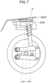
- FIGS. 6 to 7 are views respectively showing the camber angle and the caster angle of the driving wheel 300 according to the embodiment of the present invention.
- the rotation plate 800 may change the camber angle or the caster angle of the driving wheel 300 by being relatively rotated with respect to the base frame 100 or the vehicle body F.
- the rotation plate 800 with the upper and lower surfaces that extend in the diagonal directions from each other is relatively rotated with respect to the base frame 100 or the vehicle body F, the angle at which the base frame 100 is coupled to the coupling surface of the vehicle body F may be adjusted. Therefore, the camber angle and the caster angle of the driving wheel 300 coupled to the base frame 100 may vary at the same time.
- the driving wheel 300 may include a knuckle 310 coupled to the second end of the connection link 200 and a hub rotatably coupled to the knuckle 310.
- the independently driving wheel module may include: the driving device 700 fixed to the knuckle 310 and rotating the hub on the knuckle 310 when the driving device is operated.
- the knuckle 310 is coupled to the second end of the connection link 200, and as described below, the knuckle 310 may be rotatably coupled to the second end of the connection link 200.
- the hub may be rotatably coupled to the knuckle 310, and the hub may be rotated in a grounded state with the ground through a tire or the like.
- the driving device 700 may be an in-wheel motor, and may be securely coupled to the knuckle 310 to apply a rotation force to the hub when the driving device is operated.
- the driving wheel 300 includes the knuckle 310 coupled to the second end of the connection link 200 and the hub rotatably coupled to the knuckle 310.
- the knuckle 310 may be coupled to the second end of the connection link 200 so as to allow relative movement in a vertical direction with respect to the second end of the connection link 200.
- the knuckle 310 may be rotatably coupled to the second end of the connection link 200. As the knuckle 310 is rotatably coupled to the second end of the connection link 200, the knuckle 310 may be relatively moved upward and downward with respect to the second end of the connection link 200.
- the independently driving wheel module may include: a plurality of coupling links 400 that are disposed to be vertically spaced apart from each other, of which each first end is rotatably coupled to the second end of the connection link 200, and of which each second end is rotatably coupled to the knuckle 310.
- the plurality of coupling links 400 extends in a longitudinal direction according to a forward direction in which the driving wheel 300 travels by rotation thereof, and may be disposed to be spaced apart from each other in a vertical direction. Furthermore, the plurality of coupling links 400 is rotatably coupled to, at a first end thereof, to the second end of the connection link 200 while being spaced apart from each other, and the second end of the plurality of the coupling links may be rotatably coupled to the knuckle 310.
- connection link 200 and the knuckle 310 may provide a 4-bar linkage structure due to the plurality of coupling links 400, whereby the knuckle 310 may be moved upward and downward with respect to the second end of the connection link 200.
- the independently driving wheel module may include: a suspension device 500 of which a first end is coupled to the connection link 200 and a second end is connected to the driving wheel 300, the suspension device 500 absorbing vertical vibration of the driving wheel 300.
- the suspension device 500 may be a shock absorber.
- the first end of the suspension device 500 may be securely coupled to the connection link 200 and the second end thereof may be rotatably coupled to the knuckle 310 or the plurality of coupling links 400.
- the second end of the suspension device 500 may penetrate an upper coupling link 400 of the plurality of coupling links 400 and be rotatably coupled to a lower coupling link 400 thereof.
- the independently driving wheel module may include: a steering device 600 of which a first end is securely coupled to the upper end of the base frame 100, the steering device 600 configured to rotate the rotation part 110 or the connection link 200 with respect to the first end thereof.
- the steering device 600 may be a separate motor as the driving device 700.
- the steering device 600 may rotate the rotation part 110 or the connection link 200 with respect to the upper end of the base frame 100 securely coupled to the vehicle body F.
- the steering device 600 is integrally coupled to the rotation part 110 or the connection link 200.
- the steering device 600 may be rotated on the first end thereof fixed to the vehicle body F.
- the first end of the steering device 600 is connected to the upper end of the base frame 100 with a gear, thereby increasing steering torque.
- FIG. 8 is a flowchart showing a mounting method of the independently driving wheel module according to an embodiment of the present invention.
- the mounting method of the independently driving wheel module includes: interposing the rotation plate 800 between the base frame 100 and the vehicle body F in the relative rotatable manner with respect to the base frame 100 or the vehicle body F at S100; relatively rotating the rotation plate 800 with respect to the base frame 100 or the vehicle body F at S300; and securely coupling the rotation plate 800 to the base frame 100 or the vehicle body F at S400.
- the mounting method may include: primarily coupling the base frame 100 to the vehicle body F at S200 so as to prevent relative rotation.
- the rotation plate 800 obliquely inclined may be relatively rotated with respect to the base frame 100 or the vehicle body F so as to change the camber angle or the caster angle of the driving wheel 300.
- the rotation plate 800 may be securely coupled to the base frame 100 or the vehicle body F by being plastically deformed.
Landscapes
- Engineering & Computer Science (AREA)
- Mechanical Engineering (AREA)
- Chemical & Material Sciences (AREA)
- Combustion & Propulsion (AREA)
- Transportation (AREA)
- Vehicle Body Suspensions (AREA)
Claims (15)
- Fahrzeug mit einer Fahrzeugkarosserie (F) und einem unabhängig antreibenden Radmodul, mit:einem Grundrahmen (100) mit einem an einer Verbindungsfläche der Fahrzeugkarosserie (F) befestigten oberen Ende,einem ein erstes Ende und ein zweites Ende aufweisenden Verbindungsglied (200), das eine sich von dem ersten Ende des Verbindungsglieds (200) nach unten erstreckende Form aufweist; undeinem Antriebsrad (300), das auf einer Seite des zweiten Endes des Verbindungsglieds (200) angeordnet ist und mit dem zweiten Ende des Verbindungsglieds (200) verbunden ist;gekennzeichnet durchein Drehteil (110), das mit dem oberen Ende des Grundrahmens (100) derart verbunden ist, dass das Drehteil in Bezug auf das obere Ende des Grundrahmens (100) drehbar ist;wobei das erste Ende des Verbindungsglieds (200) einstückig mit dem Drehteil (110) verbunden ist;
undeine Drehplatte (800) mit einer Oberseite und einer Unterseite, die sich schräg in nicht aufeinander ausgerichtete Richtungen erstrecken, wobei die Drehplatte (800) zwischen dem Grundrahmen (100) und der Fahrzeugkarosserie (F) in Bezug auf den Grundrahmen (100) oder die Fahrzeugkarosserie (F) drehbar angeordnet ist. - Fahrzeug nach Anspruch 1, bei welchem die Drehplatte (800) mit dem Grundrahmen (100) oder der Fahrzeugkarosserie (F) derart sicher verbunden ist, dass die Drehplatte (800) in Bezug auf den Grundrahmen (100) oder die Fahrzeugkarosserie (F) drehbar ist.
- Fahrzeug nach Anspruch 2, bei welchem die Drehplatte (800) ferner ein langgestrecktes Loch aufweist, das sich entlang einer Bahn erstreckt, in welcher die Drehplatte (800) in Bezug auf den Grundrahmen (100) drehbar ist, und
wobei die Drehplatte (800) über das langgestreckte Loch mit dem Grundrahmen (100) oder der Fahrzeugkarosserie (F) verbunden ist. - Fahrzeug nach Anspruch 2, bei welchem der Grundrahmen (100) ferner eine Verbindungsnut (120) aufweist, welche in dem Grundrahmen (100) nach unten oder innen eingetieft ist, und
wobei die Drehplatte (800) durch Verriegeln in und Verbinden mit der Verbindungsnut (120) fixiert ist, während sie mit dem Grundrahmen (100) drehbar verbunden ist. - Fahrzeug nach Anspruch 1, bei welchem die Oberseite der Drehplatte (800) sich parallel zu der Verbindungsfläche der Fahrzeugkarosserie (F) erstreckt und die Unterseite der Drehplatte (800) sich parallel zu einer Oberseite des Grundrahmens (100) erstreckt, und
wobei die Verbindungsfläche der Fahrzugkarosserie (F) und die Oberseite des Grundrahmens (100) zueinander schräg geneigt sind. - Fahrzeug nach Anspruch 1, bei welchem ein Sturzwinkel oder ein Nachlaufwinkel des Antriebsrades (300) variiert, wenn die Drehplatte (800) in Bezug auf den Grundrahmen (100) oder die Fahrzeugkarosserie (F) gedreht wird.
- Fahrzeug nach Anspruch 1, bei welcher das Antriebsrad (300) einen Achsschenkel (310), der mit dem zweiten Ende des Verbindungsglieds (200) verbunden ist, und eine Nabe aufweist, die drehbar mit dem Achsschenkel (310) verbunden ist, und
wobei das unabhängig antreibende Radmodul ferner eine an dem Achsschenkel (310) befestigte und zum Drehen der Nabe auf dem Achsschenkel (310) betreibbare Antriebsvorrichtung (700) aufweist. - Fahrzeug nach Anspruch 1, bei welchem das Antriebsrad (300) einen Achsschenkel (310), der mit dem zweiten Ende des Verbindungsglieds (200) verbunden ist, und eine Nabe aufweist, die drehbar mit dem Achsschenkel (310) verbunden ist, und
wobei der Achsschenkel (310) mit dem zweiten Ende des Verbindungsglieds (200) derart verbunden ist, dass eine Relativbewegung des Achsschenkels (310) in einer vertikalen Richtung in Bezug auf das Verbindungsglied (200) möglich ist. - Fahrzeug nach Anspruch 8, ferner mit:
Verbindungsgliedern (400), die vertikal voneinander beabstandet angeordnet sind, wobei die Verbindungsglieder (400) jeweilige erste Enden, die drehbar mit dem zweiten Ende des Verbindungsglieds (200) verbunden sind, und jeweilige zweite Enden aufweist, die drehbar mit dem Achsschenkel (310) verbunden sind. - Fahrzeug nach Anspruch 1, ferner mit:
einer Federungsvorrichtung (500) mit einem ersten Ende, das mit dem Verbindungsglied (200) verbunden ist, und einem zweiten Ende, das mit dem Antriebsrad (300) verbunden ist, wobei die Federungsvorrichtung (500) dazu ausgebildet ist, vertikale Vibrationen des Antriebsrads (300) zu absorbieren. - Fahrzeug nach Anspruch 1, ferner mit:
einer Lenkvorrichtung (600) mit einem ersten Ende, das sicher mit dem oberen Ende des Grundrahmens (100) verbunden ist, wobei die Lenkvorrichtung (600) dazu ausgebildet ist, das Drehteil (110) oder das Verbindungsglied (200) an dem ersten Ende der Lenkvorrichtung (600) als Drehmittelpunkt zu drehen. - Verfahren zur Befestigung eines unabhängig antreibenden Radmoduls, gekennzeichnet durch den folgenden Schritt:
Vorsehen einer Fahrzeugkarosserie, wobei das unabhängig antreibende Radmodul aufweist:eine Drehplatte (800);einen Grundrahmen (100);ein ein erstes Ende und ein zweites Ende aufweisende Verbindungsglied (200), das eine sich von dem ersten Ende des Verbindungsglieds (200) nach unten erstreckende Form aufweist; undein Antriebsrad (300), das auf einer Seite des zweiten Endes des Verbindungsglieds (200) angeordnet ist und mit dem zweiten Ende des Verbindungsglieds (200) verbunden ist;wobei das Verfahren ferner durch die folgenden Schritte gekennzeichnet ist:Zwischenfügen der Drehplatte (800) zwischen den Grundrahmen (100) und die Fahrzeugkarosserie (F), und Befestigen eines oberen Endes des Grundrahmens (100) an einer Verbindungsfläche der Fahrzeugkarosserie (F) derart, dass die Drehplatte (800) in Bezug auf den Grundrahmen oder die Fahrzeugkarosserie drehbar ist;Drehen der Drehplatte (800) in Bezug auf den Grundrahmen (100) oder die Fahrzeugkarosserie (F); undsicheres Verbinden der Drehplatte (800) mit dem Grundrahmen (100) oder der Fahrzeugkarosserie (F),wobei der Grundrahmen (100) ein Drehteil (110) aufweist, das mit dem oberen Ende des Grundrahmens (100) derart verbunden ist, dass das Drehteil (110) in Bezug auf das obere Ende des Grundrahmens (100) drehbar ist,wobei die Drehplatte (800) eine Oberseite und eine Unterseite aufweist, die sich schräg in nicht aufeinander ausgerichtete Richtungen erstrecken. - Verfahren nach Anspruch 12, ferner mit dem Schritt:
nach dem Zwischenfügen der Drehplatte (800), primäres Verbinden des Grundrahmens (100) mit der Fahrzeugkarosserie (F), um das Drehen des Grundrahmens (100) in Bezug auf die Fahrzeugkarosserie (F) zu verhindern. - Verfahren nach Anspruch 12, bei welchem beim Drehen der Drehplatte (800), die Drehplatte (800) in Bezug auf den Grundrahmen (100) oder die Fahrzeugkarosserie (F) gedreht wird, um einen Sturzwinkel oder einen Nachlaufwinkel des Antriebsrads (300) zu verändern.
- Verfahren nach Anspruch 12, bei welchem das sichere Verbinden der Drehplatte (800) das sichere Verbinden der Drehplatte (800) mit dem Grundrahmen (100) oder dem Fahrzeugkörper (F) durch plastisches Verformen der Drehplatte (800) aufweist.
Applications Claiming Priority (1)
| Application Number | Priority Date | Filing Date | Title |
|---|---|---|---|
| KR1020200153702A KR102886000B1 (ko) | 2020-11-17 | 2020-11-17 | 독립 구동휠 모듈 및 이의 장착 방법 |
Publications (2)
| Publication Number | Publication Date |
|---|---|
| EP4000970A1 EP4000970A1 (de) | 2022-05-25 |
| EP4000970B1 true EP4000970B1 (de) | 2023-08-16 |
Family
ID=78695487
Family Applications (1)
| Application Number | Title | Priority Date | Filing Date |
|---|---|---|---|
| EP21207238.3A Active EP4000970B1 (de) | 2020-11-17 | 2021-11-09 | Fahrzeug und unabhängig angetriebenes radmodul und sein montageverfahren |
Country Status (4)
| Country | Link |
|---|---|
| US (2) | US11577783B2 (de) |
| EP (1) | EP4000970B1 (de) |
| KR (1) | KR102886000B1 (de) |
| CN (1) | CN114506183B (de) |
Families Citing this family (7)
| Publication number | Priority date | Publication date | Assignee | Title |
|---|---|---|---|---|
| KR102886000B1 (ko) * | 2020-11-17 | 2025-11-12 | 현대모비스 주식회사 | 독립 구동휠 모듈 및 이의 장착 방법 |
| KR102654193B1 (ko) | 2021-11-23 | 2024-04-03 | 현대모비스 주식회사 | 차량용 코너 모듈 장치 |
| KR102688427B1 (ko) * | 2022-06-03 | 2024-07-25 | 현대모비스 주식회사 | 차량용 코너 모듈 장치 |
| US12377693B2 (en) * | 2022-09-01 | 2025-08-05 | Aptera Motors Corp. | Rear suspension for vehicle having improved swing arm |
| IT202300001443A1 (it) * | 2023-01-31 | 2024-07-31 | Mario Burigo | Veicolo equipaggiato con moduli intercambiabili per il controllo attivo della rotazione di ogni ruota e della posizione ed orientamento del suo asse |
| WO2024215211A1 (en) * | 2023-04-14 | 2024-10-17 | Howard Wright Limited | A wheel assembly for a wheeled apparatus |
| CN118597255B (zh) * | 2024-03-13 | 2025-09-12 | 厦门金龙联合汽车工业有限公司 | 一种可控制高集成悬架角模块系统 |
Family Cites Families (30)
| Publication number | Priority date | Publication date | Assignee | Title |
|---|---|---|---|---|
| US4418938A (en) * | 1981-09-21 | 1983-12-06 | General Motors Corporation | Vehicle strut suspension with camber adjustment |
| KR0161336B1 (ko) * | 1995-07-20 | 1999-01-15 | 김상응 | 폴리글리콜산의 제조방법 |
| JP3072479B2 (ja) * | 1997-06-10 | 2000-07-31 | 丸石自転車株式会社 | 車椅子 |
| US5826894A (en) * | 1997-11-20 | 1998-10-27 | Chrysler Corporation | Alignment cam position limiter |
| US6557872B1 (en) * | 2000-10-31 | 2003-05-06 | Ingalls Engineering Company, Inc. | Replacement apparatus providing selectable camber/caster correction |
| JP2002211201A (ja) | 2001-01-12 | 2002-07-31 | Kaneda Kikai Seisakusho Ltd | 無人搬送車 |
| US7607668B2 (en) * | 2007-06-08 | 2009-10-27 | Maximum Motorsports | Caster-camber plate assemblies |
| US8075005B1 (en) * | 2008-10-06 | 2011-12-13 | Stempf Automotive Industries, Inc. | Wheel alignment apparatus |
| PL2414212T3 (pl) | 2010-05-28 | 2013-02-28 | John Victor Gano | Wielokierunkowy zespół kołowy i wielokierunkowy pojazd |
| US9296274B2 (en) * | 2012-02-27 | 2016-03-29 | John Victor Gano | Integrated system of independently-variable multi-wheel steering and road contact geometry |
| KR101448761B1 (ko) * | 2013-08-20 | 2014-10-08 | 현대자동차 주식회사 | 캐스터 능동 제어 장치 |
| US8820759B1 (en) * | 2013-10-01 | 2014-09-02 | Brian Croutcher | Plates allowing adjustment of caster and camber |
| CN107531091B (zh) * | 2015-03-13 | 2019-12-31 | 赛迈道依茨-法尔意大利股份公司 | 单个悬吊车轮转向系统以及牵引车或骑乘式割草机 |
| FR3042463B1 (fr) * | 2015-10-19 | 2018-07-13 | Poclain Hydraulics Industrie | Dispositif de braquage d'une roue directrice d'une machine roulante |
| DE102016203984A1 (de) * | 2016-03-10 | 2017-09-14 | Thyssenkrupp Ag | Radlenkbaugruppe für Kraftfahrzeuge mit Einzelradlenkung |
| DE102016209590A1 (de) * | 2016-06-01 | 2017-12-07 | Thyssenkrupp Ag | Federbeinlager zum Lagern eines Federbeins an einer Kraftfahrzeugkarosserie und ein Verfahren zum Einstellen von Fahrwerken von Kraftfahrzeugen |
| CN107160963B (zh) * | 2017-05-04 | 2020-08-21 | 大陆智源科技(北京)有限公司 | 轮式运动底盘 |
| CN207141175U (zh) * | 2017-06-09 | 2018-03-27 | 哈尔滨理工大学 | 一种医院巡检机器人用轮式足端装置 |
| DE102018107358A1 (de) | 2018-03-28 | 2019-10-02 | Schaeffler Technologies AG & Co. KG | Radmodul für ein Kraftfahrzeug |
| DE102018128060A1 (de) * | 2018-11-09 | 2020-05-14 | Schaeffler Technologies AG & Co. KG | Lenkeinrichtung für eine Kraftfahrzeuglenkung |
| JP7095121B2 (ja) * | 2019-01-08 | 2022-07-04 | 株式会社Fomm | サスペンションユニット及び車両 |
| JP2020111270A (ja) * | 2019-01-16 | 2020-07-27 | トヨタ自動車株式会社 | 転舵装置、および、それを備えた車両用車輪配設モジュール |
| DE102019106839A1 (de) * | 2019-03-18 | 2020-09-24 | Schaeffler Technologies AG & Co. KG | Radmodul |
| US10988176B2 (en) * | 2019-05-17 | 2021-04-27 | GM Global Technology Operations LLC | Component alignment system |
| JP7339930B2 (ja) * | 2020-08-19 | 2023-09-06 | 本田技研工業株式会社 | 操舵装置 |
| US11718139B2 (en) * | 2020-10-07 | 2023-08-08 | Hyundai Mobis Co., Ltd. | System and method for controlling vehicle |
| KR102886000B1 (ko) * | 2020-11-17 | 2025-11-12 | 현대모비스 주식회사 | 독립 구동휠 모듈 및 이의 장착 방법 |
| EP4019310B1 (de) * | 2020-12-28 | 2023-09-27 | Hyundai Mobis Co., Ltd. | Unabhängiges antriebsmodul |
| KR20220129934A (ko) * | 2021-03-17 | 2022-09-26 | 현대모비스 주식회사 | 모빌리티 인휠 구동모듈 |
| KR20230036598A (ko) * | 2021-09-06 | 2023-03-15 | 현대자동차주식회사 | 차량의 스케이트보드 플랫폼용 서스펜션 구조 |
-
2020
- 2020-11-17 KR KR1020200153702A patent/KR102886000B1/ko active Active
-
2021
- 2021-11-05 US US17/519,856 patent/US11577783B2/en active Active
- 2021-11-09 EP EP21207238.3A patent/EP4000970B1/de active Active
- 2021-11-17 CN CN202111361536.2A patent/CN114506183B/zh active Active
-
2023
- 2023-01-04 US US18/093,040 patent/US11851103B2/en active Active
Also Published As
| Publication number | Publication date |
|---|---|
| US11577783B2 (en) | 2023-02-14 |
| US20220153348A1 (en) | 2022-05-19 |
| EP4000970A1 (de) | 2022-05-25 |
| CN114506183B (zh) | 2023-07-18 |
| KR20220067219A (ko) | 2022-05-24 |
| CN114506183A (zh) | 2022-05-17 |
| US11851103B2 (en) | 2023-12-26 |
| KR102886000B1 (ko) | 2025-11-12 |
| US20230143749A1 (en) | 2023-05-11 |
Similar Documents
| Publication | Publication Date | Title |
|---|---|---|
| EP4000970B1 (de) | Fahrzeug und unabhängig angetriebenes radmodul und sein montageverfahren | |
| EP3403856B1 (de) | Aufhängungsvorrichtung für nichtgelenktes antriebsrad mit radmotor | |
| EP3398797B1 (de) | Automatisch neigendes fahrzeug | |
| WO2022134087A1 (zh) | 一种悬架结构、角模块系统及汽车 | |
| US20160068195A1 (en) | Battery arrangement in a two-track vehicle | |
| US12491928B2 (en) | Independent corner module | |
| US12017499B2 (en) | Suspension device for in-wheel motor | |
| US20110221157A1 (en) | Vehicle independent suspension | |
| JPH11222153A (ja) | 自動車の前輪懸架装置 | |
| US5887896A (en) | Reinforced front suspension structure of motor vehicle | |
| EP3140140B1 (de) | Radträger | |
| US7052024B2 (en) | Suspension assembly applicable to both manual and power steering systems | |
| JP2020050266A (ja) | 車両用サスペンションアーム | |
| KR20230038954A (ko) | 인휠모터용 서스펜션장치 | |
| GB2339175A (en) | A rear axle for industrial vehicles | |
| KR20230099255A (ko) | 전방 차체 구조 | |
| JPH0747844A (ja) | 自動車のパワートレイン支持構造 | |
| JP3873495B2 (ja) | サスペンション取付構造 | |
| CN223494585U (zh) | 转向角模块、车辆底盘及车辆 | |
| US10086666B2 (en) | Coupling structure for vehicle chassis members | |
| GB2577400A (en) | Crash Structure | |
| JP7816280B2 (ja) | ストラット式サスペンション装置 | |
| CN121424882A (zh) | 一种车辆悬架及底盘 | |
| KR20250179818A (ko) | 차량 프레임에 장착 가능한 인휠주행모듈 | |
| KR20250091462A (ko) | 차체 조향 및 현가 장치 |
Legal Events
| Date | Code | Title | Description |
|---|---|---|---|
| PUAI | Public reference made under article 153(3) epc to a published international application that has entered the european phase |
Free format text: ORIGINAL CODE: 0009012 |
|
| STAA | Information on the status of an ep patent application or granted ep patent |
Free format text: STATUS: REQUEST FOR EXAMINATION WAS MADE |
|
| 17P | Request for examination filed |
Effective date: 20211109 |
|
| AK | Designated contracting states |
Kind code of ref document: A1 Designated state(s): AL AT BE BG CH CY CZ DE DK EE ES FI FR GB GR HR HU IE IS IT LI LT LU LV MC MK MT NL NO PL PT RO RS SE SI SK SM TR |
|
| RBV | Designated contracting states (corrected) |
Designated state(s): AL AT BE BG CH CY CZ DE DK EE ES FI FR GB GR HR HU IE IS IT LI LT LU LV MC MK MT NL NO PL PT RO RS SE SI SK SM TR |
|
| RIC1 | Information provided on ipc code assigned before grant |
Ipc: B62D 7/15 20060101ALI20230130BHEP Ipc: B62D 7/06 20060101ALI20230130BHEP Ipc: B62D 5/04 20060101ALI20230130BHEP Ipc: B60G 3/01 20060101ALI20230130BHEP Ipc: B62D 17/00 20060101ALI20230130BHEP Ipc: B60G 7/00 20060101ALI20230130BHEP Ipc: B60G 7/02 20060101ALI20230130BHEP Ipc: B60G 3/20 20060101AFI20230130BHEP |
|
| GRAP | Despatch of communication of intention to grant a patent |
Free format text: ORIGINAL CODE: EPIDOSNIGR1 |
|
| STAA | Information on the status of an ep patent application or granted ep patent |
Free format text: STATUS: GRANT OF PATENT IS INTENDED |
|
| INTG | Intention to grant announced |
Effective date: 20230313 |
|
| GRAS | Grant fee paid |
Free format text: ORIGINAL CODE: EPIDOSNIGR3 |
|
| GRAA | (expected) grant |
Free format text: ORIGINAL CODE: 0009210 |
|
| STAA | Information on the status of an ep patent application or granted ep patent |
Free format text: STATUS: THE PATENT HAS BEEN GRANTED |
|
| AK | Designated contracting states |
Kind code of ref document: B1 Designated state(s): AL AT BE BG CH CY CZ DE DK EE ES FI FR GB GR HR HU IE IS IT LI LT LU LV MC MK MT NL NO PL PT RO RS SE SI SK SM TR |
|
| REG | Reference to a national code |
Ref country code: CH Ref legal event code: EP |
|
| REG | Reference to a national code |
Ref country code: DE Ref legal event code: R096 Ref document number: 602021004319 Country of ref document: DE |
|
| REG | Reference to a national code |
Ref country code: IE Ref legal event code: FG4D |
|
| P01 | Opt-out of the competence of the unified patent court (upc) registered |
Effective date: 20230922 |
|
| REG | Reference to a national code |
Ref country code: LT Ref legal event code: MG9D |
|
| REG | Reference to a national code |
Ref country code: NL Ref legal event code: MP Effective date: 20230816 |
|
| REG | Reference to a national code |
Ref country code: AT Ref legal event code: MK05 Ref document number: 1599706 Country of ref document: AT Kind code of ref document: T Effective date: 20230816 |
|
| PG25 | Lapsed in a contracting state [announced via postgrant information from national office to epo] |
Ref country code: GR Free format text: LAPSE BECAUSE OF FAILURE TO SUBMIT A TRANSLATION OF THE DESCRIPTION OR TO PAY THE FEE WITHIN THE PRESCRIBED TIME-LIMIT Effective date: 20231117 |
|
| PG25 | Lapsed in a contracting state [announced via postgrant information from national office to epo] |
Ref country code: IS Free format text: LAPSE BECAUSE OF FAILURE TO SUBMIT A TRANSLATION OF THE DESCRIPTION OR TO PAY THE FEE WITHIN THE PRESCRIBED TIME-LIMIT Effective date: 20231216 |
|
| PG25 | Lapsed in a contracting state [announced via postgrant information from national office to epo] |
Ref country code: SE Free format text: LAPSE BECAUSE OF FAILURE TO SUBMIT A TRANSLATION OF THE DESCRIPTION OR TO PAY THE FEE WITHIN THE PRESCRIBED TIME-LIMIT Effective date: 20230816 Ref country code: RS Free format text: LAPSE BECAUSE OF FAILURE TO SUBMIT A TRANSLATION OF THE DESCRIPTION OR TO PAY THE FEE WITHIN THE PRESCRIBED TIME-LIMIT Effective date: 20230816 Ref country code: PT Free format text: LAPSE BECAUSE OF FAILURE TO SUBMIT A TRANSLATION OF THE DESCRIPTION OR TO PAY THE FEE WITHIN THE PRESCRIBED TIME-LIMIT Effective date: 20231218 Ref country code: NO Free format text: LAPSE BECAUSE OF FAILURE TO SUBMIT A TRANSLATION OF THE DESCRIPTION OR TO PAY THE FEE WITHIN THE PRESCRIBED TIME-LIMIT Effective date: 20231116 Ref country code: NL Free format text: LAPSE BECAUSE OF FAILURE TO SUBMIT A TRANSLATION OF THE DESCRIPTION OR TO PAY THE FEE WITHIN THE PRESCRIBED TIME-LIMIT Effective date: 20230816 Ref country code: LV Free format text: LAPSE BECAUSE OF FAILURE TO SUBMIT A TRANSLATION OF THE DESCRIPTION OR TO PAY THE FEE WITHIN THE PRESCRIBED TIME-LIMIT Effective date: 20230816 Ref country code: LT Free format text: LAPSE BECAUSE OF FAILURE TO SUBMIT A TRANSLATION OF THE DESCRIPTION OR TO PAY THE FEE WITHIN THE PRESCRIBED TIME-LIMIT Effective date: 20230816 Ref country code: IS Free format text: LAPSE BECAUSE OF FAILURE TO SUBMIT A TRANSLATION OF THE DESCRIPTION OR TO PAY THE FEE WITHIN THE PRESCRIBED TIME-LIMIT Effective date: 20231216 Ref country code: HR Free format text: LAPSE BECAUSE OF FAILURE TO SUBMIT A TRANSLATION OF THE DESCRIPTION OR TO PAY THE FEE WITHIN THE PRESCRIBED TIME-LIMIT Effective date: 20230816 Ref country code: GR Free format text: LAPSE BECAUSE OF FAILURE TO SUBMIT A TRANSLATION OF THE DESCRIPTION OR TO PAY THE FEE WITHIN THE PRESCRIBED TIME-LIMIT Effective date: 20231117 Ref country code: FI Free format text: LAPSE BECAUSE OF FAILURE TO SUBMIT A TRANSLATION OF THE DESCRIPTION OR TO PAY THE FEE WITHIN THE PRESCRIBED TIME-LIMIT Effective date: 20230816 Ref country code: AT Free format text: LAPSE BECAUSE OF FAILURE TO SUBMIT A TRANSLATION OF THE DESCRIPTION OR TO PAY THE FEE WITHIN THE PRESCRIBED TIME-LIMIT Effective date: 20230816 |
|
| PG25 | Lapsed in a contracting state [announced via postgrant information from national office to epo] |
Ref country code: PL Free format text: LAPSE BECAUSE OF FAILURE TO SUBMIT A TRANSLATION OF THE DESCRIPTION OR TO PAY THE FEE WITHIN THE PRESCRIBED TIME-LIMIT Effective date: 20230816 |
|
| PG25 | Lapsed in a contracting state [announced via postgrant information from national office to epo] |
Ref country code: ES Free format text: LAPSE BECAUSE OF FAILURE TO SUBMIT A TRANSLATION OF THE DESCRIPTION OR TO PAY THE FEE WITHIN THE PRESCRIBED TIME-LIMIT Effective date: 20230816 |
|
| PG25 | Lapsed in a contracting state [announced via postgrant information from national office to epo] |
Ref country code: SM Free format text: LAPSE BECAUSE OF FAILURE TO SUBMIT A TRANSLATION OF THE DESCRIPTION OR TO PAY THE FEE WITHIN THE PRESCRIBED TIME-LIMIT Effective date: 20230816 Ref country code: RO Free format text: LAPSE BECAUSE OF FAILURE TO SUBMIT A TRANSLATION OF THE DESCRIPTION OR TO PAY THE FEE WITHIN THE PRESCRIBED TIME-LIMIT Effective date: 20230816 Ref country code: ES Free format text: LAPSE BECAUSE OF FAILURE TO SUBMIT A TRANSLATION OF THE DESCRIPTION OR TO PAY THE FEE WITHIN THE PRESCRIBED TIME-LIMIT Effective date: 20230816 Ref country code: EE Free format text: LAPSE BECAUSE OF FAILURE TO SUBMIT A TRANSLATION OF THE DESCRIPTION OR TO PAY THE FEE WITHIN THE PRESCRIBED TIME-LIMIT Effective date: 20230816 Ref country code: DK Free format text: LAPSE BECAUSE OF FAILURE TO SUBMIT A TRANSLATION OF THE DESCRIPTION OR TO PAY THE FEE WITHIN THE PRESCRIBED TIME-LIMIT Effective date: 20230816 Ref country code: CZ Free format text: LAPSE BECAUSE OF FAILURE TO SUBMIT A TRANSLATION OF THE DESCRIPTION OR TO PAY THE FEE WITHIN THE PRESCRIBED TIME-LIMIT Effective date: 20230816 Ref country code: SK Free format text: LAPSE BECAUSE OF FAILURE TO SUBMIT A TRANSLATION OF THE DESCRIPTION OR TO PAY THE FEE WITHIN THE PRESCRIBED TIME-LIMIT Effective date: 20230816 |
|
| REG | Reference to a national code |
Ref country code: DE Ref legal event code: R097 Ref document number: 602021004319 Country of ref document: DE |
|
| PLBE | No opposition filed within time limit |
Free format text: ORIGINAL CODE: 0009261 |
|
| STAA | Information on the status of an ep patent application or granted ep patent |
Free format text: STATUS: NO OPPOSITION FILED WITHIN TIME LIMIT |
|
| PG25 | Lapsed in a contracting state [announced via postgrant information from national office to epo] |
Ref country code: MC Free format text: LAPSE BECAUSE OF FAILURE TO SUBMIT A TRANSLATION OF THE DESCRIPTION OR TO PAY THE FEE WITHIN THE PRESCRIBED TIME-LIMIT Effective date: 20230816 |
|
| PG25 | Lapsed in a contracting state [announced via postgrant information from national office to epo] |
Ref country code: LU Free format text: LAPSE BECAUSE OF NON-PAYMENT OF DUE FEES Effective date: 20231109 |
|
| 26N | No opposition filed |
Effective date: 20240517 |
|
| PG25 | Lapsed in a contracting state [announced via postgrant information from national office to epo] |
Ref country code: MC Free format text: LAPSE BECAUSE OF FAILURE TO SUBMIT A TRANSLATION OF THE DESCRIPTION OR TO PAY THE FEE WITHIN THE PRESCRIBED TIME-LIMIT Effective date: 20230816 Ref country code: LU Free format text: LAPSE BECAUSE OF NON-PAYMENT OF DUE FEES Effective date: 20231109 Ref country code: IT Free format text: LAPSE BECAUSE OF FAILURE TO SUBMIT A TRANSLATION OF THE DESCRIPTION OR TO PAY THE FEE WITHIN THE PRESCRIBED TIME-LIMIT Effective date: 20230816 Ref country code: SI Free format text: LAPSE BECAUSE OF FAILURE TO SUBMIT A TRANSLATION OF THE DESCRIPTION OR TO PAY THE FEE WITHIN THE PRESCRIBED TIME-LIMIT Effective date: 20230816 |
|
| REG | Reference to a national code |
Ref country code: BE Ref legal event code: MM Effective date: 20231130 |
|
| REG | Reference to a national code |
Ref country code: IE Ref legal event code: MM4A |
|
| PG25 | Lapsed in a contracting state [announced via postgrant information from national office to epo] |
Ref country code: IE Free format text: LAPSE BECAUSE OF NON-PAYMENT OF DUE FEES Effective date: 20231109 |
|
| PG25 | Lapsed in a contracting state [announced via postgrant information from national office to epo] |
Ref country code: BE Free format text: LAPSE BECAUSE OF NON-PAYMENT OF DUE FEES Effective date: 20231130 |
|
| PG25 | Lapsed in a contracting state [announced via postgrant information from national office to epo] |
Ref country code: IE Free format text: LAPSE BECAUSE OF NON-PAYMENT OF DUE FEES Effective date: 20231109 Ref country code: BE Free format text: LAPSE BECAUSE OF NON-PAYMENT OF DUE FEES Effective date: 20231130 |
|
| PG25 | Lapsed in a contracting state [announced via postgrant information from national office to epo] |
Ref country code: BG Free format text: LAPSE BECAUSE OF FAILURE TO SUBMIT A TRANSLATION OF THE DESCRIPTION OR TO PAY THE FEE WITHIN THE PRESCRIBED TIME-LIMIT Effective date: 20230816 |
|
| PG25 | Lapsed in a contracting state [announced via postgrant information from national office to epo] |
Ref country code: BG Free format text: LAPSE BECAUSE OF FAILURE TO SUBMIT A TRANSLATION OF THE DESCRIPTION OR TO PAY THE FEE WITHIN THE PRESCRIBED TIME-LIMIT Effective date: 20230816 |
|
| REG | Reference to a national code |
Ref country code: CH Ref legal event code: PL |
|
| REG | Reference to a national code |
Ref country code: CH Ref legal event code: PL |
|
| PG25 | Lapsed in a contracting state [announced via postgrant information from national office to epo] |
Ref country code: CH Free format text: LAPSE BECAUSE OF NON-PAYMENT OF DUE FEES Effective date: 20241130 |
|
| PG25 | Lapsed in a contracting state [announced via postgrant information from national office to epo] |
Ref country code: CY Free format text: LAPSE BECAUSE OF FAILURE TO SUBMIT A TRANSLATION OF THE DESCRIPTION OR TO PAY THE FEE WITHIN THE PRESCRIBED TIME-LIMIT; INVALID AB INITIO Effective date: 20211109 |
|
| PGFP | Annual fee paid to national office [announced via postgrant information from national office to epo] |
Ref country code: GB Payment date: 20250922 Year of fee payment: 5 |
|
| PGFP | Annual fee paid to national office [announced via postgrant information from national office to epo] |
Ref country code: FR Payment date: 20250925 Year of fee payment: 5 |
|
| PG25 | Lapsed in a contracting state [announced via postgrant information from national office to epo] |
Ref country code: TR Free format text: LAPSE BECAUSE OF FAILURE TO SUBMIT A TRANSLATION OF THE DESCRIPTION OR TO PAY THE FEE WITHIN THE PRESCRIBED TIME-LIMIT Effective date: 20230816 |
|
| PGFP | Annual fee paid to national office [announced via postgrant information from national office to epo] |
Ref country code: DE Payment date: 20250922 Year of fee payment: 5 |
|
| PG25 | Lapsed in a contracting state [announced via postgrant information from national office to epo] |
Ref country code: HU Free format text: LAPSE BECAUSE OF FAILURE TO SUBMIT A TRANSLATION OF THE DESCRIPTION OR TO PAY THE FEE WITHIN THE PRESCRIBED TIME-LIMIT; INVALID AB INITIO Effective date: 20211109 |