EP4000908A1 - Kombination umfassend eine reifenheizpresse und einen reifencontainer - Google Patents
Kombination umfassend eine reifenheizpresse und einen reifencontainer Download PDFInfo
- Publication number
- EP4000908A1 EP4000908A1 EP21207388.6A EP21207388A EP4000908A1 EP 4000908 A1 EP4000908 A1 EP 4000908A1 EP 21207388 A EP21207388 A EP 21207388A EP 4000908 A1 EP4000908 A1 EP 4000908A1
- Authority
- EP
- European Patent Office
- Prior art keywords
- container
- tire
- press
- rails
- curing press
- Prior art date
- Legal status (The legal status is an assumption and is not a legal conclusion. Google has not performed a legal analysis and makes no representation as to the accuracy of the status listed.)
- Granted
Links
Images




Classifications
-
- B—PERFORMING OPERATIONS; TRANSPORTING
- B29—WORKING OF PLASTICS; WORKING OF SUBSTANCES IN A PLASTIC STATE IN GENERAL
- B29D—PRODUCING PARTICULAR ARTICLES FROM PLASTICS OR FROM SUBSTANCES IN A PLASTIC STATE
- B29D30/00—Producing pneumatic or solid tyres or parts thereof
- B29D30/06—Pneumatic tyres or parts thereof (e.g. produced by casting, moulding, compression moulding, injection moulding, centrifugal casting)
- B29D30/0601—Vulcanising tyres; Vulcanising presses for tyres
- B29D30/0603—Loading or unloading the presses
Definitions
- the invention relates to a combination comprising a tire curing press and a tire container.
- the vulcanization takes place in a vulcanization mold installed in a tire container, the tire container being mounted in an exchangeable manner in the tire curing press and the vulcanization mold can therefore be changed by exchanging the tire container in order to vulcanize tires of different sizes.
- the tire containers have a container bottom plate with a central receiving hole and a container top part. Since the tire containers weigh several hundred kilograms, they are transported to and from the tire curing press using industrial trucks (forklifts). In particular, it is currently common to push the tire container directly from the industrial truck into the tire curing press.
- the tire containers are aligned in the tire curing presses using a centering ring, which engages in the central receiving hole in the bottom plate of the container.
- the rotational alignment is done manually and by eye. Milled cutouts on the tire container and tire curing press serve as reference points. When replacing a tire container, a large number of steps must be carried out.
- steps include, among other things, closing steam valves, opening a drain valve, dismantling and disassembling the bladder, removing a sealing ring (O-ring), removing the screws holding the container bottom plate, loosening the screws holding the container top part, removing various sensors if necessary, dismantling the steam lines, removing the dismantled tire container from the tire curing press, inserting the desired tire container, centering and aligning the tire container using the millings mentioned, fixing the top part of the container to the top part of the press, attaching the steam lines to the top part of the press, fixing the top part of the container using the screws, fixing the bottom plate of the container to the Tire curing press using the screws, assembly of the adapter ring, calibration of the "Tire-Loader", preparation of the bladder and assembly of the O-ring as well as pre-heating of the tire curing press. Due to the large number of manual steps to be carried out, the entire replacement process takes around two hours.
- the object of the invention is to provide a combination of the type mentioned at the outset, by means of which the tire container in the tire heating mold can be replaced more efficiently and ergonomically than before, with the time required being reduced in particular and a high level of occupational safety being ensured. Furthermore, a corresponding method using the combination is to be shown.
- the combination according to the invention is characterized in particular by the use of a container changing trolley, a special positioning system and a special guidance system.
- the elements of the positioning system are located both on the tire curing press and on the tire container and enable an "automatic" translational, centric and rotational alignment of the tire container on the container changing trolley or the tire curing press.
- the guide system enables the tire container to be quickly inserted into and removed from the tire curing press and enables the container bottom plate to be quickly fixed.
- the exchange of a tire container is therefore at least largely automated, with--in comparison to the current procedure--the time required is significantly reduced and work safety is significantly increased.
- the rails on which the second positioning elements can be guided are U-rails which, when the tire container is placed in the tire curing press, clamp the lower container plate to the press plate via the second positioning elements in their blocking position.
- the U-rails are arranged on the side of the press platen on the tire curing press.
- the guide system on the container changing trolley located guide rails, which either connect to the rails arranged on the container changing trolley or, when the container changing trolley is coupled, connect to the rails arranged next to the press platen.
- the positioning system for the rotational alignment of the tire container on the container changing trolley has adapter pieces located on the container bottom plate as second positioning elements that can be guided on the rails of the guide system, which in particular each enclose an edge piece in the shape of a segment of a circle of the container bottom plate and one that runs parallel to the chord of the circle segment have side surface.
- the adapter pieces advantageously assume several functions, namely rotational alignment of the tire container on the container changing trolley, simple guidance of the tire container in or on the rails and--in combination with the U-rails--clamping of the lower container plate to the press plate.
- the positioning system for the translational alignment of the tire container in the tire curing press has at least one stop located on the tire curing press as the first positioning element, in particular as the first positioning element an end stop on each U-rail for the adapter pieces of the container bottom plate.
- the stop or the end stops is or are easy to implement. If the U-rails are equipped with the end stops, the adapter pieces have another function, they contribute to the translatory alignment of the tire container.
- the centric alignment is made possible by these measures in a simple and reliable manner.
- the combination comprises an assembly system for assembly of the container upper part on the press upper part when the tire curing press is closed, which is formed by T-slots formed in the container upper part and on the press upper part with pivoting clamping cylinders that can be brought into and out of engagement with the T-slots.
- Such a mounting system allows for quick and easy mounting and dismounting of the container top.
- the tire container can therefore be exchanged in a particularly efficient manner.
- Such a heating system contributes to the automation of the container changing process.
- the fixing device enables the container changing trolley to be quickly coupled and uncoupled and, at the same time, a corresponding alignment of the container changing trolley and thus also of the tire container to be mounted in the tire curing press.
- Such a container changing trolley enables the tire container to be handled particularly quickly and safely, in particular the tire container being easily pushed in and out, thereby reducing the time required for replacing a tire container and increasing occupational safety. It is therefore ideally suited for the combination according to the invention. Its use in combination therefore solves the task in a particularly advantageous manner.
- the container changing trolley has a support foot on the frame that can be variably adjusted in the vertical direction.
- the support leg forms in combination with the fixing and variable position detachable positioning pins a compensating mechanism, by means of which any unevenness on the ground can be compensated, whereby the tire container can be pushed into and out of the tire curing press very easily.
- the introduction and assembly of the tire container can be automated, at least to a large extent, and enables rapid assembly of the tire container in the tire curing press.
- FIG. 1 shows a combination of a tire curing press 1, a device that can be coupled to this and in 1 container changing trolley 2 coupled to this with a tire container 3.
- a substantially circular-cylindrical tire container 3 containing a vulcanization mold In order to vulcanize green tires by means of the tire curing press 1, a substantially circular-cylindrical tire container 3 containing a vulcanization mold must be mounted in a lying position. By exchanging the tire container 3 , differently designed, in particular differently dimensioned, green tires can be vulcanized in the tire curing press 1 .
- the tire container 3 is transported on a container changing trolley 2 by means of an industrial truck, in particular a low lift truck, then the container changing trolley 2 is coupled to the tire curing press 1, the tire container 3 is introduced into the tire curing press 1 and mounted in it.
- To replace a mounted tire container 3 it must first be dismantled, placed on the "empty" container changing trolley 2 coupled to the tire curing press 1, and the container changing trolley 2 must be uncoupled from the tire curing press 1 and moved away.
- the tire container 3 is removed from the container changing trolley 2, and the desired tire container 3 is placed on the container changing trolley 2.
- the container changing trolley 2 is then transported with the desired tire container 3 , the container changing trolley 2 is coupled and the desired tire container 3 is mounted in the tire curing press 1 .
- the combination according to the invention comprises a positioning system and a guidance system.
- the positioning system has first positioning elements formed on the tire curing press 1 and second positioning elements formed on the tire container 3 .
- the management system also includes elements on the tire curing press 1 and on the tire container 3. Furthermore, a mounting system for the tire container 3 is preferably provided.
- the basic design of the tire container 3, the container changing trolley 2 and the tire curing press 1 will be discussed first below.
- the elements of the guide system, the positioning system and the assembly system result from a subsequent functional description.
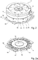
- the tire container 3 consists of a substantially annular container bottom plate 4 ( Figure 2a ) And one of these removable, essentially circular-cylindrical container shell 5 with a used circular container top plate 6 together.
- the container bottom plate 4 has a central receiving hole 4a passing through it, four pairs of elongated grooves 4b offset by 90° from one another, which pass through the container bottom plate 4 and extend from the outer circumference of the container bottom plate 4 in the radial direction into it, two diametrically opposed opposing adapter pieces 4d, each formed centrally between two pairs of elongated grooves 4a, and an integrated heating circuit (not visible) with two connection points 4c located on the outer circumference.
- the adapter pieces 4d each enclose an edge piece in the shape of a segment of a circle of the container lower plate 4 and each have a side surface 4d' running parallel to the chord of the segment of a circle and a receiving hole 4d" on its upper side 2
- the container upper part 5 next to the container upper plate 6 is provided with four T-grooves 5b offset by 90°, which are formed on the outer circumference, reach up to the container upper plate 6 and are formed essentially opposite to the elongated grooves 4b of the container lower plate 4.
- the upper part of the container 5 has an integrated heating circuit (not shown) with connection points 5a located on the outer circumference.
- the tire curing press 1 comprises a frame 7, a stationary, horizontally constructed, annular press plate 8 ( 1 ), a press upper part 9 that can be moved up and down in the vertical direction and has a housing-like heat shield 9a (in 10 shown without a heat shield 9a), a vertically movable heating bladder, not shown, and a two-part heating medium connection 10 ( 10 ) with a lower connecting part 10a ( 10 ) for the connection points 4c of the container bottom plate 4 ( 2 ) and an upper connection part 10b arranged on the press upper part 9 for the connection points 5a of the container upper part 5 ( 2 ).
- a heating medium can be introduced into the lower connection part 10a and into the upper connection part 10b, so that the mounted tire container 3 can be heated to the desired vulcanization temperature.
- the container changing trolley 2 has a cuboid frame 11 made up of a frame with fork mounts 11a on the underside Transport of the container change trolley 2 by means of the aforementioned industrial truck, two roller conveyors 12, two lateral guide rails 13 and a feed device 14.
- a tire container 3 positioned on the container changing trolley 2 can be displaced linearly in the direction indicated by the double arrow P 1 (transport direction).
- the two roller conveyors 12, the two guide rails 13 and the feed device 14 are located on the upper side of the frame 11.
- the guide rails 13 are aligned parallel to one another and are mounted on the frame 11 on the outside.
- the roller conveyors 12 are located next to each other in the area between the guide rails 13, are offset downwards relative to them and each have a large number of rollers 12a located in matching height positions, which are mounted horizontally and freely rotatably and are oriented perpendicular to the guide rails 13.
- the feed device 14 comprises a rectangular base plate 14a, two rod-shaped drivers 14b and a chain drive 14c.
- the rectangular base plate 14a can be displaced linearly in grooves 14a' formed in the guide rails 13 on the inside of the frame.
- the rod-shaped carriers 14b are pivoted in the vertical direction on the rectangular base plate 14a, are located next to the guide rails 13 and each have an engagement element 14b' ( Figure 3a ) for the mounting holes 4d" of the adapter pieces 4d of the container bottom plate 4 ( Figure 3a ) on.
- the chain drive 14c acts on the base plate 14a, has two gears 14c' located between the roller conveyors 12 and a hand crank 14c'' acting on at least one of the gears 14c' for actuating the chain drive 14c.
- the tire container is 3 (in Figure 3a only the container bottom plate 4 is shown) to be positioned on the container changing trolley 2 in such a way that the adapter pieces 4d rest against the guide rails 13 and the engagement elements 14b' of the drivers 14b can be inserted into the receiving holes 4d".
- the adapter pieces 4d therefore allow exactly two possible rotational alignments of the Tire container 3 on the container changing trolley 2, wherein the tire container 3 is to be positioned in the orientation explained on the container changing trolley 2. This also ensures that the mentioned connection points 4c, 5a ( 2 ) can be connected to the corresponding connection part 10a, 10b of the heating medium connection 10.
- the container changing trolley 2 can be coupled via its frame 11 to the frame 7 of the tire curing press 1 by means of a fixing device 15, with the components of the fixing device 15 being in corresponding positions partly on the frame 11 and partly on the frame 7.
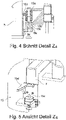
- the components of the positioning and fixing device 15 located on the frame 11 of the container changing trolley 2 are two plastic rollers 15a, which are arranged at the edge on the lower area of the frame 11, are oriented in the vertical direction, are designed as hollow cylinders, are freely rotatable and are each mounted on a positioning bushing 15b rest on a centering hole 15b' which is open towards the bottom ( 4 ).
- the components of the positioning and fixing device 15 located on the frame 7 of the tire curing press 1 are two positioning pins 15c arranged in the lower area of the frame 7 and one L-shaped angled guide plate 15d each located above the positioning pins 15c.
- the positioning pins 15c are aligned in the vertical direction to match the centering holes 15b' ( 4 ) formed and can be fixed and released in a variable vertical position.
- the container changing trolley 2 is then lowered by actuating the industrial truck accordingly, so that the positioning pins 15c are introduced into the centering holes 15b' ( 4 ).
- the positioning pins 15c can thus be brought into engagement with the centering bores 15b' in a releasable manner, so that the positioning pins 15c together with the positioning bushings 15b form two pin connections which can be fixed and released.
- a support foot 19 ( 3 ) which is located opposite to the rollers 15a. By adjusting the vertical positions of the support foot 19 and positioning pins 15c ( figure 5 ) any unevenness on the ground can be leveled out.
- the press plate 8 has a diameter that corresponds to the diameter of the tire container 3 shown, a horizontal, flat upper side 8a, a centering ring 8b formed centrally on this for the receiving hole 4a of the container lower plate 4 ( Figure 2a ) and an alignment element 8c formed on the upper side 8a and protruding from it (cf 6 ) for one of the elongated grooves 4b ( Figure 2a ) of the container bottom panel 4.
- the position and design of the centering ring 8b and the alignment element 8c correlates with the position and design of the receiving hole 4a or one of the elongated grooves 4b.
- the centering ring 8b is also designed in such a way that the aforementioned heating bladder can be raised from below through the centering ring 8b.
- U-rails 16 On the side of the press plate 8 are two diametrically opposite U-rails 16 which are aligned parallel to one another and have U-legs 16a ( 6 ), one end stop 16b each facing away from the coupled container changing trolley 2 (cf. 8 ) and a roller strip 16c ( 9 ).
- the U-rails 16 are each located on two hydraulic cylinders 17 attached to the frame 7 (see also Figures 6 to 9 ), by means of which the U-rails 16 can be raised and lowered in the vertical direction and thus in relation to the press platen 8 .
- 6 shows the U-rails 16 in the raised position (release position)
- 7 shows the U-rails 16 in the lowered position (blocking position).
- the tire container 3 can be pushed into the tire curing press 1 from the coupled container changing trolley 2, with a distance between the container lower plate 4 and the press plate 8 remains and the tire container 3 can be pushed over the centering ring 8b ( 6 ).
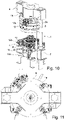
- the upper part of the press 9 has four pivoting clamping cylinders 18, which are arranged offset from one another by 90° and are provided with the T-slots 5b ( 2 ) of the upper container part 5 can be engaged in a releasable manner, so that the upper container part 5 can be coupled to and decoupled from the upper press part 9 .
- the tire container 3 to be brought in is preheated at a preheating station via the connection points 4c, 5a before it is placed on the container changing trolley 2.
- the tire container 3 is transported on the container changing trolley 2 and the container changing trolley 2 is coupled to the tire curing press 1 via the fixing device 15 ( 1 ). If necessary, any unevenness on the ground can be leveled out after coupling by means of the support foot 19 and the positioning pins 15c, as already mentioned. If not already done, the tire curing press 1 is opened, the U-rails 16 next to the press platen 8 are brought into their release position by actuating the hydraulic cylinders 17 ( 1 , 6 ) and the tire container 3 is connected to the feed device 14 in the manner described ( 1 , Figure 3a ).
- the tire container 3 By actuating the feed device 14, the tire container 3 is pushed over the press platen 8 ( 6 ), whereby the adapter pieces 4d of the container bottom plate 4 slide on the roller rails 16c into the U-rails 16 ( 9 ) until the adapter pieces 4d hit the end stops 16b ( 8 , 10 ), whereby a translational alignment of the tire container 3 in the tire curing press 1 is achieved.
- the tire container 3 is then uncoupled from the feed device 14 and the U-rails 16 are moved down with the hydraulic cylinders 17 (cf 6 With 7 ), as a result of which the adapter pieces 4d lose contact with the roller strips 16c and come into contact with the upper U-legs 16a of the U-rails 16 ( 7 ) and in this way the container bottom plate 4 is clamped to the press plate 8 in a non-positive manner ( 7 , blocking position of the U-rails 16), at the same time the alignment element 8c ( 6 ) engages in one of the elongated grooves 4b of the container bottom plate 4 and the centering ring 8b of the press plate 8 engages in the receiving hole 4a of the container bottom plate 4 ( 7 ), whereby the tire container 3 is rotationally and centrically aligned (finely adjusted).
- the container sub-plate 4 is preferably simultaneously connected via its connection points 4c ( 2 ) coupled to the lower connection part 10a of the heating medium connection 10 ( 10 ). Afterward the upper part of the press 9 is lowered and the upper part of the container 5 is fastened to the upper part of the press 9 via its T-slots 5b by means of the pivoting clamping cylinder 18 .
- the pivoting clamping cylinders 18 first engage in the T-slots 5b, are then rotated by 90° about a vertical axis (positive connection) and then pull the upper container part 5 in a vertical direction towards the upper press part 9 (positive connection), which preferably simultaneously pulls the upper container part 5 via its connection points 5a ( 2 ) is coupled to the upper connection part 10b of the heating medium connection 10 (in 2 the coupled state is indicated).
- the tire curing press 1 is then opened by moving the press upper part 9 upwards ( 10 ).
- the coupling of the lower container plate 3 to the lower connection part 10a of the heating medium connection 10 and the coupling of the upper container part 5 to the upper connection part 10b of the heating medium connection 10 can optionally only take place after the lower container plate 3 has been clamped by means of the U-rails 16 or after the Container upper part 5 was attached by means of the swivel clamp cylinder 18.
- the tire curing press 1 After uncoupling the container changing trolley 2 from the frame 7 of the tire curing press 1, the tire curing press 1 is ready for use. After inserting a green tire into the tire curing press 1, the tire curing press 1 is closed, with the press upper part 9 together with the coupled upper container part 5 moving down. The green tire is vulcanized, with the aforementioned heating bladder being retracted into the interior of the tire container 3 and inflated. The finished vulcanized tire is removed after the tire curing press 1 has been opened.
- the container changing trolley 2 is therefore coupled to the tire curing press 1 and, if necessary, any unevenness on the ground is leveled out, as already explained.
- the tire curing press 1 is closed and the pivoting clamping cylinders 18 are rotated so that the upper part of the container 5 is detached from the upper part of the press 9 .
- the tire curing press 1 is opened and the U-rails 16 are raised by means of the hydraulic cylinder 17, so that the alignment element 8c is lifted out of the corresponding elongated groove 4b of the container bottom plate 4 and the Tire container 3 is raised above the level of the centering ring 8b (ie the U-rails 16 are moved from the blocking position to the release position).
- the feed device 14 is connected to the adapter pieces 4d, the tire container 3 is pulled out of the tire curing press 1 and placed on the container changing trolley 2.
- the container changing trolley 2 can be moved away if necessary by means of an industrial truck.
- the guidance system, the positioning system and the assembly system which have already been mentioned at the outset, are therefore formed by the following elements.
- the guide system includes the vertically movable U-rails 16 on the tire curing press 1 and the guide rails 13 on the container changing trolley 2.
- the first positioning elements of the positioning system located on the tire curing press 1 are formed by the centering ring 8b located on the press plate 8, the alignment element 8c located thereon and by the end stops 16b of the U-rails 16.
- the second positioning elements located on the tire container 3 are the receiving hole 4a, the elongated grooves 4b and the adapter pieces 4d. The positioning system enables the translational, centric and rotational alignment of the tire container 3.
- the assembly system includes the pivoting clamping cylinder 18 on the upper press part 9 and the corresponding T-slots 5b in the upper container part 5.
- the assembly system enables the upper container part 5 to be mounted on the upper press part 9 when the tire container 3 is lowered onto the press plate 8.
- the invention is not limited to the exemplary embodiment described.
- the combination according to the invention comprises at least one container changing trolley.
- the combination can in particular comprise two container changing trolleys, namely a first one for the tire container to be dismantled located in the tire curing press and a second one for the respective one to be assembled in the tire curing press tire container.
- the desired tire container can already be positioned on this second container changing trolley while the tire container to be exchanged is being dismantled. The replacement process can be accelerated accordingly.
- the container changing trolley(s) 2 can have any drive, for example a rack and pinion drive, instead of the chain drive 14c.
- a spindle drive or the like can be provided, for example.
- the size of the tire container 3 is usually dependent on the size of the vulcanization mold and therefore on the respective tire dimension.
- the adapter pieces 4d of the lower container plate 4 are preferably made correspondingly larger.
- the mounting system for mounting the upper part of the container can be adapted to the size of the upper part of the container, in particular in a manner known per se.
- the container bottom plate 4 can in particular only have a single groove 4b or four grooves 4b, which are designed analogously to the pairs of grooves 4b in the exemplary embodiment.
- any suitable lifting device for raising and lowering the U-rails 16 can be provided.
- pneumatic cylinders, electrically operated cylinders or the like come into question.
- the guide system can include U-rails arranged on the side of the press plate 8 when the container changing trolley 2 is coupled, which can be moved in the vertical direction with a lifting device configured on the container changing trolley 2.
- the lifting device is therefore located on the container changing trolley 2.
- any suitable rails can be used instead of U-rails, in particular it is not necessary for the rails to clamp the lower container plate 4 to the press plate 8 in their blocking position (lowered position), since the lower container plate 4 can be clamped to the press plate 8 by means of the first and second Positioning is secured accordingly against displacement.
- the function of the end stops 16b can alternatively be accomplished by another or several other first positioning element(s) which are not arranged directly on the U-rails 16 or rails .
- the translational alignment of the tire container 3 in the tire curing press 1 could be accomplished by means of a stop located at a different position.
Landscapes
- Engineering & Computer Science (AREA)
- Mechanical Engineering (AREA)
- Heating, Cooling, Or Curing Plastics Or The Like In General (AREA)
- Moulds For Moulding Plastics Or The Like (AREA)
Abstract
Description
- Die Erfindung betrifft eine Kombination umfassend eine Reifenheizpresse und einen Reifencontainer.
- Bei der Reifenfertigung werden aufgebaute Reifenrohlinge in Reifenheizpressen vulkanisiert und derart die fertigen Reifen hergestellt. Die Vulkanisation erfolgt dabei in einer in einem Reifencontainer eingebauten Vulkanisationsform, wobei der Reifencontainer auf austauschbare Weise in der Reifenheizpresse montiert ist und sich daher durch Austausch des Reifencontainers die Vulkanisationsform wechseln lässt, um verschieden groß dimensionierte Reifen zu vulkanisieren. Die Reifencontainer weisen eine Containerunterplatte mit einem zentrischen Aufnahmeloch und einen Containeroberteil auf. Da die Reifencontainer mehrere hundert Kilogramm wiegen, werden diese mit Flurförderfahrzeugen (Gabelstaplern) zur Reifenheizpresse an- und abtransportiert. Insbesondere ist es aktuell üblich, die Reifencontainer direkt vom Flurförderfahrzeug in die Reifenheizpressen einzuschieben. Die Ausrichtung der Reifencontainer in den Reifenheizpressen erfolgt über einen Zentrierring, welcher in das zentrische Aufnahmeloch der Containerunterplatte greift. Die rotatorische Ausrichtung erfolgt händisch und per Augenmaß. Als Bezugspunkte dienen am Reifencontainer und der Reifenheizpresse vorhandene Ausfräsungen. Beim Austauschen eines Reifencontainers ist eine Vielzahl von Schritten durchzuführen. Zu diesen Schritten gehören unter anderem Schließen von Dampfventilen, Öffnen eines Ablassventils, Demontage und Auseinanderbauen des Heizbalges, Entfernen eines Dichtringes (O-Ring), Entfernen der die Containerunterplatte haltenden Schrauben, Lösen der den Containeroberteil haltenden Schrauben, ggf. Entfernung diverser Sensoren, Demontage der Dampfleitungen, Herausnahme des demontieren Reifencontainers aus der Reifenheizpresse, Einbringen des gewünschten Reifencontainers, Zentrieren und Ausrichten des Reifencontainers mittels der erwähnten Ausfräsungen, Fixieren des Containeroberteils am Pressenoberteil, Anbringen der Dampfleitungen am Pressenoberteil, Fixieren des Containeroberteils mittels der Schrauben, Fixieren der Containerunterplatte an der Reifenheizpresse mittels der Schrauben, Montage des Adapterringes, Kalibrieren des "Tire-Loaders", Vorbereitung des Heizbalges und Montage des O-Ringes sowie Vorheizen der Reifenheizpresse. Aufgrund der Vielzahl an manuell durchzuführenden Schritten dauert der gesamte Austauschvorgang zirka zwei Stunden.
- Der Erfindung liegt die Aufgabe zugrunde, eine Kombination der eingangs genannten Art zur Verfügung zu stellen, mittles welcher ein Austausch des Reifencontainers in der Reifenheizform auf rationellere und ergonomischere Weise als bisher durchführbar ist, wobei insbesondere der Zeitbedarf verringert und eine hohe Arbeitssicherheit sichergestellt werden sollen. Ferner soll ein entsprechendes Verfahren unter Verwendung der Kombination aufgezeigt werden.
- Gelöst wird die gestellte Aufgabe erfindungsgemäß durch eine Kombination aus
- a) einer Reifenheizpresse mit einer Pressenplatte und einem Pressenoberteil,
- b) einem in der Reifenheizpresse montierbaren Reifencontainer mit einer Containerunterplatte und einem Containeroberteil,
- c) einem an der Reifenheizpresse an- und/ abkoppelbaren Containerwechseltrolley,
- d) einem Führungssystem zum Ein- und Ausbringen des Reifencontainers bei angekoppeltem Containerwechseltrolley, welches seitlich der Pressenplatte angeordnete Schienen oder am Containerwechseltrolley angeordnete, bei angekoppelten Containerwechseltrolley seitlich der Pressenplatte positionierbare Schienen umfasst, wobei die Schienen in vertikaler Richtung verfahrbar und durch Absenken in eine Blockierposition und durch Anheben in eine Freigabeposition bringbar sind,
- e) einem Positioniersystem zur translatorischen, zentrischen und rotatorischen Ausrichtung des Reifencontainers umfassend erste Positionierelemente an der
- Reifenheizpresse und zweite an der Containerunterplatte befindliche Positionierelemente, zu welchen auf den Schienen des Führungssystems führbare zweite Positionierelemente gehören,
- wobei die ersten und die zweiten Positionierelemente derart zusammenwirken, dass bei angekoppelten Containerwechseltrolley und in Freigabeposition befindlichen Schienen der Reifencontainer in die Reifenheizpresse ein- und aus dieser ausschiebbar ist und
- bei in die Reifenheizpresse eingeschobenen Reifencontainer und in Blockierposition befindlichen Schienen der Reifencontainer ausgerichtet ist.
- Die erfindungsgemäße Kombination zeichnet sich insbesondere durch den Einsatz eines Containerwechseltrolleys, eines speziellen Positioniersystems und eines speziellen Führungssystems aus. Die Elemente des Positioniersystems befindenden sich dabei sowohl an der Reifenheizpresse als auch am Reifencontainer und ermöglichen eine "automatische" translatorische, zentrische und rotatorische Ausrichtung des Reifencontainers am Containerwechseltrolley bzw. der Reifenheizpresse. Das Führungssystem ermöglicht ein schnelles Einbringen des Reifencontainers in und ein schnelles Ausbringen des Reifencontainers aus der Reifenheizpresse und ermöglicht eine schnelle Fixierung des Containerunterplatte. Der Austausch eines Reifencontainers erfolgt daher zumindest weitgehend automatisiert, wobei - im Vergleich zur derzeit üblichen Vorgangsweise - der Zeitaufwand deutlich verringert und die Arbeitssicherheit deutlich erhöht sind.
- Gemäß einer bevorzugten Ausführung sind die Schienen, auf welchen die zweiten Positionierelemente führbar sind, U-Schienen, welche bei in der Reifenheizpresse eingebrachten Reifencontainer in ihrer Blockierposition die Containerunterplatte über die zweiten Positionierelemente an die Pressenplatte klemmen. Diese ermöglichen eine zusätzliche Sicherung (Fixierung) der ausgerichteten Containerunterplatte an der Pressenplatte.
- Bei dieser Ausführung ist es bevorzugt, wenn die U-Schienen seitlich der Pressenplatte an der Reifenheizpresse angeordnet sind.
- Gemäß einer weiteren bevorzugten Ausführung weist das Führungssystem am Containerwechseltrolley befindliche Führungsleisten auf, welche
entweder an die am Containerwechseltrolley angeordneten Schienen anschließen oder bei angekoppeltem Containerwechseltrolley an die neben der Pressenplatte angeordnete Schienen anschließen. - Dies ermöglich ein besonders komfortables Handling des Reifencontainers.
- Gemäß einer weiteren bevorzugten Ausführung weist das Positioniersystem zur rotatorischen Ausrichtung des Reifencontainers auf dem Containerwechseltrolley als zweite, auf den Schienen des Führungssystems führbare Positionierelemente an der Containerunterplatte befindliche Adapterstücke auf, welche insbesondere jeweils ein kreissegmentförmiges Randstück der Containerunterplatte einfassen und eine parallel zur Sehne des Kreissegmentes verlaufende Seitenfläche aufweisen. Die Adapterstücke übernehmen vorteilhafter Weise mehrere Funktionen, nämlich eine rotatorische Ausrichtung des Reifencontainers am Containerwechseltrolley, eine einfache Führung des Reifencontainers in bzw. auf den Schienen sowie - in Kombination mit den U-Schienen - das Klemmen der Containerunterplatte an die Pressenplatte.
- Gemäß einer weiteren bevorzugten Ausführung weist das Positioniersystem zur translatorischen Ausrichtung des Reifencontainers in der Reifenheizpresse als erstes Positionierelement zumindest einen an der Reifenheizpresse befindlichen Anschlag, insbesondere als erste Positionierelemente je einen Endanschlag an jeder U-Schiene für die Adapterstücke der Containerunterplatte, auf. Der Anschlag bzw. die Endanschläge ist bzw. sind einfach zu realisieren. Sind die U-Schienen mit den Endanschlägen versehen, kommt den Adapterstücken eine weitere Funktion zu, sie tragen zur translatorischen Ausrichtung des Reifencontainers bei.
- Ferner ist es bevorzugt, wenn das Positioniersystem zur rotatorischen Ausrichtung des Reifencontainers in der Reifenheizpresse
- als zweites Positionierelement eine in der Containerunterplatte ausgebildete Nut und als erstes Positionierelement ein auf der Pressenplatte befindliches Ausrichtelement aufweist,
- wobei bei in Blockierposition befindlichen Schienen das Ausrichtelement in die Nut eingreift und bei in Freigabeposition befindlichen Schienen das Ausrichtelement mit der Nut außer Eingriff ist.
- Der Blockiervorgang und die rotatorische Ausrichtung (Feinjustierung) des Reifencontainers bzw. der Containerunterplatte sind durch diese Maßnahmen auf geschickte Weise miteinander gekoppelt.
- Gemäß einer weiteren bevorzugten Ausführung weist das Positioniersystem zur zentrischen Ausrichtung des Reifencontainers in der Reifenheizpresse
- als zweites Positionierelement ein in der Containerunterplatte ausgebildetes zentrisches Aufnahmeloch und
- als erstes Positionierelement einen auf der Pressenplatte befindlichen Zentrierring aufweist, wobei bei in Blockierposition befindlichen Schienen der Zentrierring in das Aufnahmeloch eingreift und bei in Freigabeposition befindlichen Schienen mit dem Aufnahmeloch außer Eingriff ist.
- Die zentrische Ausrichtung ist durch diese Maßnahmen auf einfache und zuverlässige Weise ermöglicht.
- Bei einer weiteren bevorzugten Ausführung umfasst die Kombination ein Montagesystem zur Montage des Containeroberteils am Pressenoberteil bei geschlossener Reifenheizpresse, welches von im Containeroberteil ausgebildeten T-Nuten und am Pressenoberteil befindlichen, mit den T-Nuten in und außer Eingriff bringbaren Schwenkklemmzylindern gebildet ist.
- Ein derartiges Montagesystem ermöglicht ein schnelles und einfaches Montieren und Demontieren des Containeroberteils. Der Reifencontainer lässt sich daher auf besonders rationelle Weise austauschen.
- Gemäß einer weiteren bevorzugten Ausführung weist die Kombination ein Heizsystem zum Erwärmen des montierten Reifencontainers auf, welches Folgendes umfasst:
- Einen in der Containerunterplatte integrierten Heizkreislauf mit Anschlussstellen,
- einen im Containeroberteil integrierten Heizkreislauf mit Anschlussstellen und
- einen Heizmediumanschluss mit einem an die Anschlussstellen der Containerunterplatte ankoppelbaren Anschlussteil und einem an die Anschlussstellen des Containeroberteils ankoppelbaren Anschlussteil.
- Ein derartiges Heizsystem trägt zur Automatisierung des Containerwechselvorganges bei.
- Eine weitere bevorzugte Ausführung der Kombination ist dadurch gekennzeichnet, dass sie eine Fixiereinrichtung zum An- und Abkoppeln des Containerwechseltrolleys an der Reifenheizpresse aufweist, welche Folgendes umfasst:
- Zwei am Containerwechseltrolley angebrachte, auf je einer Positionierungsbuchse aufsitzende, frei drehbar gelagerte, in vertikaler Richtung ausgerichtete Rollen,
- zwei an der Reifenheizpresse angebrachte, L-förmig gewinkelte Führungsplatten, an welchen die Rollen abrollbar sind, und
- zwei an der Reifenheizpresse angebrachte mit den Positionierungsbuchsen in und außer Eingriff bringbare, insbesondere in variabler vertikaler Position, fixier- und lösbare Positionierungsstifte.
- Die Fixiereinrichtung ermöglicht ein schnelles und An- und Abkoppeln des Containerwechseltrolleys sowie gleichzeitig eine entsprechende Ausrichtung des Containerwechseltrolleys und damit auch des in der Reifenheizpresse zu montierenden Reifencontainers.
- Die Erfindung betrifft ferner einen Containerwechseltrolley für eine erfindungsgemäße Kombination umfassend:
- Ein Gestell mit Gabelzinkenaufnahmen,
- zumindest einen am Gestell angeordneten Rollenförderer, auf welchem der Reifencontainer verschiebbar ist,
- zwei seitlich am Gestell angeordnete parallele Führungsleisten zur Führung des Reifencontainers und
- eine am Gestell angeordnete, in den Führungsleisten verschiebbare, an die Containerunterplatte des Reifencontainers an- und abkoppelbare Vorschubeinrichtung zum linearen Bewegen des Reifencontainers auf dem Rollenförderer.
- Ein derartiger Containerwechseltrolley ermöglicht ein besonders schnelles und sicheres Handling des Reifencontainers, insbesondere ein einfaches Ein- und Ausschieben des Reifencontainers, wodurch der Zeitbedarf für den Austausch eines Reifencontainers verringert und die Arbeitssicherheit erhöht sind. Er ist daher ideal für die erfindungsgemäße Kombination geeignet. Seine Verwendung in der Kombination löst die gestellte Aufgabe daher auf eine besonders vorteilhafte Weise.
- Es ist bevorzugt, wenn der Containerwechseltrolley am Gestell einen in vertikaler Richtung variabel verstellbaren Stützfuß aufweist. Ist ferner die erwähnte Fixierungseinrichtung vorgesehen, bildet der Stützfuß in Kombination mit den in variabler Position fixier- und lösbaren Positionierungsstiften einen Ausgleichmechanismus, mittels welchem sich etwaige Unebenheiten am Untergrund ausgleichen lassen, wodurch sich der Reifencontainer sehr komfortabel in die Reifenheizpresse einschieben und aus dieser herausschieben lässt.
- Was das Verfahren betrifft, wird die gestellte Aufgabe erfindungsgemäß gelöst unter Verwendung der erfindungsgemäßen Kombination sowie insbesondere unter Verwendung des erfindungsgemäßen Containerwechseltrolleys, wobei das Verfahren folgende, nacheinander ablaufende Schritte aufweist:
- i. Ankoppeln eines den Reifencontainer tragenden Containerwechseltrolleys an der Reifenheizpresse,
- ii. Einschieben des Reifencontainers in die geöffnete Reifenheizpresse, wobei der Reifencontainer mittels des Positioniersystems translatorisch ausgerichtet wird,
- iii. Zentrisches und rotatorisches Ausrichten des Reifencontainers in der Reifenheizpresse mittels der Positioniersystems,
- iv. Schließen der Reifenheizpresse,
- v. Montage des Containeroberteils am Pressenoberteil,
- vi. In Schritt iii. oder nach Schritt v. Anklemmen der Containerunterplatte an der Pressenplatte.
- Das Einbringen und Montieren des Reifencontainers lässt sich bei diesem Verfahren zumindest Großteils automatisieren und ermöglicht ein rasches Montieren des Reifencontainers in der Reifenheizpresse.
- Weitere Merkmale, Vorteile und Einzelheiten der Erfindung werden nun anhand der Zeichnung, die schematisch ein Ausführungsbeispiel der Erfindung zeigt, näher erläutert. Dabei zeigen
-
Fig. 1 eine Kombination aus einer Reifenheizpresse, einem Reifencontainer und einem Containerwechseltrolley gemäß einer Ausführungsvariante der Erfindung, -
Fig. 2 den Reifencontainer, -
Fig. 2a eine Containerunterplatte des Reifencontainers, -
Fig. 3 den Containerwechseltrolley, -
Fig. 3a eine Ansicht auf ein Detail des Containerwechseltrolleys ausFig. 3 , -
Fig. 4 ein Schnittansicht des Details Z4 derFig. 1 , -
Fig. 5 eine Ansicht im Bereich des Details Z4, wobei nur der zur Reifenheizpresse gehörende Bereich gezeigt ist, -
Fig. 6 eine vereinfachte Rückansicht gemäß der inFig. 1 durch den Peil S6 angedeuteten Sichtrichtung mit einem Teilschnitt, wobei sich der Reifencontainer in der Reifenheizpresse befindet, -
Fig. 7 eine weitere, zuFig. 6 analoge Rückansicht, -
Fig. 8 eine Detailansicht gemäß der inFig. 1 durch den Peil S8 angedeuteten Sichtrichtung, wobei sich der Reifencontainer in der Reifenheizpresse befindet, -
Fig. 9 eine Detailansicht gemäß der inFig. 1 durch den Peil S9 angedeuteten Sichtrichtung, wobei sich der Reifencontainer in der Reifenheizpresse befindet, -
Fig. 10 die Reifenheizpresse mit montiertem Reifencontainer und -
Fig. 11 eine vereinfachte Draufsicht auf die Reifenheizpresse. - In einigen Figuren sind zum besseren Verständnis der Erfindung einzelne Bauteile bzw. Elemente nicht gezeigt.
-
Fig. 1 zeigt eine Kombination aus einer Reifenheizpresse 1, einem an dieser ankoppelbaren und inFig. 1 an dieser ankoppelten Containerwechseltrolley 2 mit einem Reifencontainer 3. - Um mittels der Reifenheizpresse 1 Reifenrohlinge zu vulkanisieren, ist in dieser ein eine Vulkanisationsform enthaltender, im Wesentlichen kreiszylindrischer Reifencontainer 3 in liegender Position zu montieren. Durch Austausch des Reifencontainers 3 können in der Reifenheizpresse 1 unterschiedlich ausgeführte, insbesondere unterschiedlich dimensionierte, Reifenrohlinge vulkanisiert werden.
- Der Reifencontainer 3 wird auf einem Containerwechseltrolley 2 mittels eines Flurförderfahrzeuges, insbesondere einem Niederhubwagen, antransportiert, anschließend wird der Containerwechseltrolley 2 an die Reifenheizpresse 1 angekoppelt, der Reifencontainer 3 in die Reifenheizpresse 1 eingebracht und in dieser montiert. Zum Austausch eines montierten Reifencontainers 3 ist dieser vorab zu demontieren, auf den "leeren" an der Reifenheizpresse 1 angekoppelten Containerwechseltrolley 2 aufzubringen und der Containerwechseltrolley 2 von der Reifenheizpresse 1 abzukoppeln und wegzubewegen. Der Reifencontainer 3 wird vom Containerwechseltrolley 2 abgenommen, und der gewünschten Reifencontainer 3 wird auf den Containerwechseltrolley 2 aufgebracht. Nachfolgend wird der Containerwechseltrolley 2 mit dem gewünschten Reifencontainer 3 antransportiert, der Containerwechseltrolley 2 wird angekoppelt und der gewünschte Reifencontainer 3 in der Reifenheizpresse 1 montiert.
- Die erfindungsgemäße Kombination umfasst ein Positioniersystem und ein Führungssystem. Das Positioniersystem weist an der Reifenheizpresse 1 ausgebildete erste Positionierelemente und am Reifencontainer 3 ausgebildete zweite Positionierelemente auf. Das Führungssystem umfasst ebenfalls Elemente an der Reifenheizpresse 1 und am Reifencontainer 3. Ferner ist bevorzugt noch ein Montagesystem für den Reifencontainer 3 vorgesehen. Nachfolgend wird zuerst auf die grundsätzliche Ausgestaltung des Reifencontainers 3, des Containerwechseltrolleys 2 und der Reifenheizpresse 1 eingegangen. Im Rahmen einer anschließenden Funktionsbeschreibung ergeben sich die Elemente des Führungssystems, des Positioniersystems und des Montagesystems.
-
Fig. 2 zeigt einen Reifencontainer 3. Der Reifencontainer 3 setzt sich aus einer im Wesentlichen kreisringförmigen Containerunterplatte 4 (Fig. 2a ) und einem von dieser abnehmbaren, im Wesentlichen kreiszylindrischen Containeroberteil 5 mit einer eingesetzten kreisförmigen Containeroberplatte 6 zusammen. WieFig. 2a zeigt, weist die Containerunterplatte 4 ein sie durchsetzendes, zentrisches Aufnahmeloch 4a, vier zueinander um 90° versetzt ausgebildete Paare von länglichen Nuten 4b, welche die Containerunterplatte 4 durchsetzen und sich vom äußeren Umfang der Containerunterplatte 4 in radialer Richtung in diese hineinerstrecken, zwei einander diametral gegenüberliegende, jeweils mittig zwischen zwei Paaren von länglichen Nuten 4a ausgebildete Adapterstücke 4d und einen integrierten Heizkreislauf (nicht sichtbar) mit zwei am äußeren Umfang befindlichen Anschlussstellen 4c auf. Die Adapterstücke 4d fassen jeweils ein kreissegmentförmiges Randstück der Containerunterplatte 4 ein und weisen jeweils eine parallel zur Sehne des Kreissegmentes verlaufende Seitenfläche 4d' und an ihrer Oberseite ein Aufnahmeloch 4d" auf. GemäßFig. 2 ist der Containeroberteil 5 neben der Containeroberplatte 6 mit vier zueinander um 90° versetzt ausgebildeten T-Nuten 5b versehen, welche am äußeren Umfang ausgebildet sind, bis zur Containeroberplatte 6 reichen und im Wesentlichen gegenüberliegend zu den länglichen Nuten 4b der Containerunterplatte 4 ausgebildet sind. Ferner weist der Containeroberteil 5 einen integrierten Heizkreislauf (nicht gezeigt) mit am äußeren Umfang befindlichen Anschlussstellen 5a auf. - Gemäß
Fig. 1 undFig. 10 umfasst die Reifenheizpresse 1 ein Gestell 7, eine ortsfeste, waagrecht ausgebildete, kreisringförmige Pressenplatte 8 (Fig. 1 ), einen in vertikaler Richtung auf- und abbewegbaren Pressenoberteil 9 mit gehäuseartigem Hitzeschild 9a (inFig. 10 ohne Hitzeschild 9a gezeigt), einen vertikal verfahrbaren nicht gezeigten Heizbalg und einen zweigeteilten Heizmediumanschluss 10 (Fig. 10 ) mit einem neben der Pressenplatte 8 am Gestell 7 angeordneten unteren Anschlussteil 10a (Fig. 10 ) für die Anschlussstellen 4c der Containerunterplatte 4 (Fig. 2 ) und einem am Pressenoberteil 9 angeordneten oberen Anschlussteil 10b für die Anschlussstellen 5a des Containeroberteils 5 (Fig. 2 ). In den unteren Anschlussteil 10a und in den oberen Anschlussteil 10b ist ein Heizmedium einleitbar, sodass der montierte Reifencontainer 3 auf die gewünschte Vulkanisationstemperatur erhitzt werden kann. - Gemäß
Fig. 3 weist der Containerwechseltrolley 2 ein quaderförmiges, aus Rahmen aufgebautes Gestell 11 mit an der Unterseite befindlichen Gabelzinkenaufnahmen 11a zum Transport des Containerwechseltrolleys 2 mittels des erwähnten Flurförderfahrzeuges, zwei Rollenförderer 12, zwei seitliche Führungsleisten 13 und eine Vorschubeinrichtung 14 auf. Ein am Containerwechseltrolley 2 positionierter Reifencontainer 3 ist gemäß der durch den Doppelpfeil P1 angedeuteten Richtung auf lineare Weise verschiebbar (Transportrichtung). - Die zwei Rollenförderer 12, die zwei Führungsleisten 13 und die Vorschubeinrichtung 14 befinden sich an der Oberseite des Gestells 11. Die Führungsleisten 13 sind parallel zueinander ausgerichtet und außenseitig auf dem Gestell 11 montiert. Die Rollenförderer 12 befinden sich nebeneinander im Bereich zwischen den Führungsleisten 13, sind gegenüber diesen nach unten abgesetzt und weisen jeweils eine Vielzahl von in übereinstimmenden Höhenpositionen befindliche Rollen 12a auf, welche horizontal sowie frei drehbar gelagert und senkrecht zu den Führungsleisten 13 orientiert sind. Die Vorschubeinrichtung 14 umfasst eine rechteckige Basisplatte 14a, zwei stabförmige Mitnehmer 14b und einen Kettenantrieb 14c. Die rechteckige Basisplatte 14a ist in gestellinnenseitig in den Führungsleisten 13 ausgebildeten Nuten 14a' linear verschiebbar. Die stabförmigen Mitnehmer 14b sind an der rechteckigen Basisplatte 14a in vertikaler Richtung schwenkbar gelagert, befinden sich neben den Führungsleisten 13 und weisen je ein Eingriffelement 14b' (
Fig. 3a ) für die Aufnahmelöcher 4d" der Adapterstücke 4d der Containerunterplatte 4 (Fig. 3a ) auf. Der Kettenantrieb 14c wirkt auf die Basisplatte 14a, weist zwei zwischen den Rollenförderern 12 befindliche Zahnräder 14c' und eine zumindest auf eines der Zahnräder 14c' wirkende Handkurbel 14c" zur Betätigung des Kettenantriebes 14c auf. - Wie insbesondere
Fig. 3a zeigt, ist der Reifencontainer 3 (inFig. 3a ist nur die Containerunterplatte 4 gezeigt) derart am Containerwechseltrolley 2 zu positionieren, dass die Adapterstücke 4d an den Führungsleisten 13 anliegen und die Eingriffelemente 14b' der Mitnehmer 14b in die Aufnahmelöcher 4d" einbringbar sind. Die Adapterstücke 4d gestatten daher genau zwei mögliche rotatorische Ausrichtungen des Reifencontainers 3 am Containerwechseltrolley 2, wobei der Reifencontainer 3 in der erläuterten Ausrichtung am Containerwechseltrolley 2 zu positionieren ist. Dadurch ist gleichzeitig sichergestellt, dass die erwähnten Anschlussstellen 4c, 5a (Fig. 2 ) an den entsprechenden Anschlussteil 10a, 10b des Heizmediumanschlusses 10 anschließbar sind. - Gemäß
Fig. 1 ist der Containerwechseltrolley 2 über sein Gestell 11 am Gestell 7 der Reifenheizpresse 1 mittels einer Fixiereinrichtung 15 ankoppelbar, wobei sich die Bauteile der Fixiereinrichtung 15 in korrespondierenden Positionen zum Teil am Gestell 11 und zum Teil am Gestell 7 befinden. WieFig. 3 zeigt, sind die am Gestell 11 des Containerwechseltrolleys 2 befindlichen Bauteile der Positionier- und Fixereinrichtung 15 zwei randseitig am unteren Bereich des Gestells 11 angeordnete, in vertikaler Richtung orientierte, als Hohlzylinder ausgeführte, frei drehbar gelagerte Kunststoffrollen 15a, welche jeweils auf einer Positionierungsbuchse 15b mit einer nach unten geöffneten Zentrierbohrung 15b' aufsitzen (Fig. 4 ). GemäßFig. 5 sind die am Gestell 7 der Reifenheizpresse 1 befindlichen Bauteile der Positionier- und Fixereinrichtung 15 zwei am unteren Bereich des Gestells 7 angeordnete Positionierungsstifte 15c und je eine oberhalb der Positionierungsstifte 15c befindliche L-förmig gewinkelte Führungsplatte 15d. Die Positionierungsstifte 15c sind in vertikaler Richtung ausgerichtet, passend zu den Zentrierbohrungen 15b' (Fig. 4 ) ausgebildet und in variabler vertikaler Position fixier- und lösbar. Zum Ankoppeln eines Containerwechseltrolleys 2 wird dieser mittels des Flurförderfahrzeuges an die Reifenheizpresse 1 herangefahren, wobei die Kunststoffrollen 15a (Fig. 3 ,Fig. 4 ) an den Führungsplatten 15d (Fig. 5 ) abrollen und derart die Zentrierbohrungen 15b' gegenüber den Positionierungsstiften 15c ausgerichtet werden. Anschließend wird der Containerwechseltrolley 2 durch entsprechendes Betätigen des Flurförderfahrzeuges abgesenkt, sodass die Positionierungsstifte 15c in die Zentrierbohrungen 15b' eingebracht werden (Fig. 4 ). Die Positionierungsstifte 15c sind somit auflösbare Weise mit den Zentrierbohrungen 15b' in Eingriff bringbar, sodass die Positionierungsstifte 15c gemeinsam mit den Positionierungsbuchsen 15b zwei fixier- und lösbare Stiftverbindung bilden. - Ferner ist am unteren Bereich des Gestelles 11 des Containerwechseltrolleys 2 ein in vertikaler Richtung variabel verstellbarer Stützfuß 19 (
Fig. 3 ) angeordnet, welcher sich gegenüberliegend zu den Rollen 15a befindet. Durch Einstellen der vertikalen Positionen des Stützfußes 19 und der Positionierungsstifte 15c (Fig. 5 ) lassen sich etwaige Unebenheiten am Untergrund ausgleichen. - Wie
Fig. 1 ferner zeigt, weist die Pressenplatte 8 eine mit dem Durchmesser des gezeigten Reifencontainers 3 korrespondieren Durchmesser, eine waagrechte, ebene Oberseite 8a, einen zentrisch auf dieser ausgebildeten Zentrierring 8b für das Aufnahmeloch 4a der Containerunterplatte 4 (Fig. 2a ) und ein auf der Oberseite 8a ausgebildetes, von dieser abragendes Ausrichtelement 8c (vergleicheFig. 6 ) für eine der länglichen Nuten 4b (Fig. 2a ) der Containerunterplatte 4 auf. Die Position und Ausführung des Zentrierringes 8b und des Ausrichtelementes 8c korreliert mit der Position und Ausführung des Aufnahmeloches 4a bzw. einer der länglichen Nuten 4b. Der Zentrierring 8b ist ferner derart ausgeführt, dass der erwähnte Heizbalg von unten durch den Zentrierring 8b hochfahrbar ist. - Seitlich der Pressenplatte 8 befinden sich zwei einander diametral gegenüberliegende, parallel zueinander ausgerichtete, liegende U-Schienen 16 mit zur Oberseite 8a der Pressenplatte 8 und zueinander weisenden U-Schenkeln 16a (
Fig. 6 ), je einem dem angekoppelten Containerwechseltrolley 2 abgewandten Endanschlag 16b (vergl.Fig. 8 ) und einer an ihrem unteren U-Schenkel 16a eingebauten Rollenleiste 16c (Fig. 9 ). Die U-Schienen 16 befinden sind jeweils auf zwei am Gestell 7 befestigten Hydraulikzylindern 17 (siehe auchFig. 6 bis 9 ), mittels welchen die U-Schienen 16 in vertikaler Richtung und somit gegenüber der Pressenplatte 8 anheb- und absenkbar sind.Fig. 6 zeigt die U-Schienen 16 in angehobener Position (Freigabeposition),Fig. 7 zeigt die U-Schienen 16 in abgesenkter Position (Blockierposition). In Freigabeposition der U-Schienen 16 und nachdem erforderlichenfalls mittels des Stützfußes 19 und der Positionierungsstifte 15c etwaige Unebenheiten am Untergrund ausgeglichen wurden, ist der Reifencontainer 3 vom angekoppelten Containerwechseltrolley 2 in die Reifenheizpresse 1 einschiebbar, wobei zwischen der Containerunterplatte 4 und der Pressenplatte 8 ein Abstand verbleibt und der Reifencontainer 3 über den Zentrierring 8b schiebbar ist (Fig. 6 ). - Wie
Fig. 10 in Kombination mitFig. 11 zeigt, weist der Pressenoberteil 9 vier Schwenkklemmzylinder 18 auf, welche um 90° zueinander versetzt angeordnet und mit den T-Nuten 5b (Fig. 2 ) des Containeroberteils 5 auflösbare Weise in Eingriff bringbar sind, sodass der Containeroberteil 5 am Pressenoberteil 9 an- und abkoppelbar ist. - Nachfolgend wird die Vorgangsweise zum Ein- und Ausbringen bzw. zum Austauschen eines Reifencontainers 3 erläutert.
- Zunächst kann es vorgesehen sein, den einzubringenden Reifencontainer 3 vor dem Aufbringen auf den Containerwechseltrolley 2 an einer Vorheizstation, über die Anschlussstellen 4c, 5a vorzuwärmen.
- Der Reifencontainer 3 wird auf dem Containerwechseltrolley 2 antransportiert und der Containerwechseltrolley 2 an der Reifenheizpresse 1 über die Fixiereinrichtung 15 angekoppelt (
Fig. 1 ). Falls erforderlich werden nach dem Ankoppeln mittels des Stützfußes 19 und der Positionierungsstifte 15c etwaige Unebenheiten am Untergrund ausgeglichen, wie bereists erwähnt. Falls noch nicht geschehen, wird die Reifenheizpresse 1 geöffnet, die U-Schienen 16 neben der Pressenplatte 8 durch Betätigen der Hydraulikzylinder 17 in ihre Freigabeposition gebracht (Fig. 1 ,Fig. 6 ) und der Reifencontainer 3 wird mit der Vorschubeinrichtung 14 auf die beschriebene Weise verbunden (Fig. 1 ,Fig. 3a ). Durch Betätigen der Vorschubeinrichtung 14 wird der Reifencontainer 3 über die Pressenplatte 8 geschoben (Fig. 6 ), wobei die Adapterstücke 4d der Containerunterplatte 4 auf den Rollenleisten 16c in die U-Schienen 16 gleiten (Fig. 9 ) bis die Adapterstücke 4d an den Endanschlägen 16b anschlagen (Fig. 8 ,Fig. 10 ), wodurch eine translatorische Ausrichtung des Reifencontainers 3 in der Reifenheizpresse 1 erreicht ist. Anschließend wird der Reifencontainer 3 von der Vorschubeinrichtung 14 abgekoppelt und die U-Schienen 16 werden mit den Hydraulikzylindern 17 nach unten gefahren (vergleicheFig. 6 mitFig. 7 ), wodurch die Adapterstücke 4d den Kontakt zu den Rollenleisten 16c verlieren und mit den oberen U-Schenkeln 16a der U-Schienen 16 in Kontakt treten (Fig. 7 ) und derart die Containerunterplatte 4 kraftschlüssig auf die Pressenplatte 8 geklemmt wird (Fig. 7 , Blockierposition der U-Schienen 16), wobei gleichzeitig das Ausrichtelement 8c (Fig. 6 ) in eine der länglichen Nuten 4b der Containerunterplatte 4 und der Zentrierring 8b der Pressenplatte 8 in das Aufnahmeloch 4a der Containerunterplatte 4 greift (Fig. 7 ), wodurch der Reifencontainer 3 rotatorisch und zentrisch ausgerichtet (feinjustiert) wird. Ferner wird die Containerunterplatte 4 dabei vorzugsweise gleichzeitig über ihre Anschlussstellen 4c (Fig. 2 ) an den unteren Anschlussteil 10a des Heizmediumanschlusses 10 angekoppelt (Fig. 10 ). Anschließend wird der Pressenoberteil 9 heruntergefahren und der Containeroberteil 5 über seine T-Nuten 5b mittels der Schwenkklemmzylinder 18 am Pressenoberteil 9 befestigt. Dabei greifen die Schwenkklemmzylinder 18 zunächst in die T-Nuten 5b, werden anschließend um eine Hochachse um 90° verdreht (formschlüssige Verbindung) und ziehen den Containeroberteil 5 nachfolgend in vertikaler Richtung an den Pressenoberteil 9 heran (kraftschlüssige Verbindung), wodurch bevorzugt gleichzeitig der Containeroberteil 5 über seine Anschlussstellen 5a (Fig. 2 ) an den oberen Anschlussteil 10b des Heizmediumanschlusses 10 angekoppelt wird (inFig. 2 ist der angekoppelte Zustand angedeutet). Nachfolgend wird die Reifenheizpresse 1 durch Nachobenfahren des Pressenoberteils 9 geöffnet (Fig. 10 ). Das Ankoppeln der Containerunterplatte 3 an den unteren Anschlussteil 10a des Heizmediumanschlusses 10 sowie das Ankoppeln des Containeroberteils 5 an den oberen Anschlussteil 10b des Heizmediumanschlusses 10 kann optional jeweils auch erst dann erfolgen, nachdem die Containerunterplatte 3 mittels der U-Schienen 16 geklemmt bzw. nachdem der Containeroberteil 5 mittles der Schwenkklemmzylinder 18 befestigt wurde. - Nach Abkoppeln des Containerwechseltrolleys 2 vom Gestell 7 der Reifenheizpresse 1 ist die Reifenheizpresse 1 einsatzbereit. Nach Einbringen eines Reifenrohlings in die Reifenheizpresse 1 wird die Reifenheizpresse 1 geschlossen, wobei der Pressenoberteil 9 mitsamt angekoppeltem Containeroberteil 5 nach unten fährt. Der Reifenrohling wird vulkanisiert, wobei der erwähnte Heizbalg ins Innere des Reifencontainers 3 eingefahren und aufgeblasen wird. Der fertig vulkanisierte Reifen wird nach Öffnen der Reifenheizpresse 1 entnommen.
- Zur Demontage des Reifencontainers 3 wird in entsprechend umgekehrter Reihenfolge vorgegangen. Es wird also der Containerwechseltrolley 2 an die Reifenheizpresse 1 angekoppelt und falls erforderlich werden etwaige Unebenheiten am Untergrund ausgeglichen, wie bereits erläutert. Die Reifenheizpresse 1 wird geschlossen und die Schwenkklemmzylinder 18 werden verdreht, sodass der Containeroberteil 5 vom Pressenoberteil 9 gelöst wird. Die Reifenheizpresse 1 wird geöffnet und die U-Schienen 16 werden mittels der Hydraulikzylinder 17 hochgefahren, sodass das Ausrichtelement 8c aus der entsprechenden länglichen Nut 4b der Containerunterplatte 4 gehoben und der Reifencontainer 3 über das Niveau des Zentrierringes 8b angehoben wird (d.h. die U-Schienen 16 werden von der Blockierposition in die Freigabeposition bewegt). Die Vorschubeinrichtung 14 wird an die Adapterstücke 4d angebunden, der Reifencontainer 3 aus der Reifenheizpresse 1 herausgezogen und auf den Containerwechseltrolley 2 aufgebracht. Mittles eines Flurförderfahrzeuges kann der Containerwechseltrolley 2 bei Bedarf weggefahren werden.
- Das Führungssystem, das Positioniersystem und das Montagesystem, welche eingangs bereits erwähnt wurden, sind daher durch folgende Elemente gebildet.
- Das Führungssystem umfasst die vertikal verfahrbaren U-Schienen 16 an der Reifenheizpresse 1 sowie die Führungsleisten 13 am Containerwechseltrolley 2.
- Die ersten, an der Reifenheizpresse 1 befindlichen Positionierelemente des Positioniersystems sind durch den an der Pressenplatte 8 befindlichen Zentrierring 8b, das an dieser befindliche Ausrichtelement 8c sowie durch die Endanschläge 16b der U-Schienen 16 gebildet. Die am Reifencontainer 3 befindlichen zweiten Positionierelemente sind das Aufnahmeloch 4a, die länglichen Nuten 4b und die Adapterstücke 4d. Das Positioniersystem ermöglicht die translatorische, zentrische und rotatorische Ausrichtung des Reifencontainers 3.
- Das Montagesystem umfasst die am Pressenoberteil 9 befindlichen Schwenkklemmzylinder 18 und die korrespondieren T-Nuten 5b im Containeroberteil 5. Das Montagesystem ermöglicht die Montage des Containeroberteils 5 am Pressenoberteil 9 bei auf die Pressenplatte 8 abgesenktem Reifencontainer 3.
- Die Erfindung ist auf das beschriebene Ausführungsbeispiel nicht beschränkt.
- Die erfindungsgemäße Kombination umfasst zumindest einen Containerwechseltrolley. Ferner kann die Kombination insbesondere zwei Containerwechseltrolleys umfassen, nämlich einen ersten für den in der Reifenheizpresse befindlichen, zu demontierenden Reifencontainer und einen zweiten für den jeweils in der Reifenheizpresse zu montierenden Reifencontainer. Auf diesem zweiten Containerwechseltrolley kann der jeweils gewünschte Reifencontainer bereits positioniert werden, während der auszutauschende Reifencontainer gerade demontiert wird. Der Austauschvorgang lässt sich dementsprechend beschleunigen.
- Der bzw. die Containerwechseltrolley(s) 2 kann bzw. können anstelle des Kettenantriebes 14c einen beliebigen Antrieb, beispielsweise einen Zahnstangenantrieb, aufweisen. Anstatt der erwähnten Handkurbel 14c" kann beispielsweise ein Spindelantrieb oder dergleichen vorgesehen sein.
- Die Größe der Reifencontainer 3 ist üblicherweise von der Größe der Vulkanisationsform und daher von der jeweiligen Reifendimension abhängig. Bevorzugt sind bei kleineren Reifencontainern 3 - im Vergleich zu größeren Reifencontainern 3 - die Adapterstücke 4d der Containerunterplatte 4 entsprechend größer ausgeführt. Das Montagesystem zur Montage des Containeroberteils lässt sich insbesondere in an sich bekannter Weise an die Größe des Containeroberteils entsprechend anpassen.
- Die Containerunterplatte 4 kann insbesondere nur eine einzige Nut 4b oder vier Nuten 4b, welche analog zu den Paaren Nuten 4b im Ausführungsbeispiel ausgebildet sind, aufweisen.
- Anstelle der erwähnten Hydraulikzylinder 17 kann eine beliebige geeignete Hubeinrichtung zum Anheben und Absenken der U-Schienen 16 vorgesehen sein. Beispielsweise kommen Pneumatikzylinder, elektrische betätigbare Zylinder oder dergleichen in Frage.
- Das Führungssystem kann anstelle der neben der Pressenplatte 8 befindlichen U-Schienen 16 am Containerwechseltrolley 2 befindliche, bei angekoppelten Containerwechseltrolley 2 seitlich der Pressenplatte 8 angeordnete U-Schienen umfassen, welche mit einer am Containerwechseltrolley 2 ausgebildeten Hubeinrichtung in vertikaler Richtung verfahrbar sind. Bei dieser Variante befindet sich die Hubeinrichtung also am Containerwechseltrolley 2. Diese U-Schienen werden beim Ein- und Ausbringen eines Reifencontainers 3 in vertikaler Richtung entsprechend verfahren und der Containerwechseltrolley 2 bleibt bevorzugt während der Vulkanisation an der Reifenheizpresse angekoppelt. Alternativ kann auch vorgesehen sein, dass die U-Schienen nachdem sie in ihre Blockierposition gefahren sind (d.h. nach Einbringen und Absenken des Reifencontainers auf die Pressenplatte) durch Wegbewegen (Abkoppeln) des Containerwechseltrolleys aus der Reifenheizpresse herausgezogen werden.
- Bei sämtlichen Varianten können anstelle von U-Schienen beliebig geeignete Schienen verwendet werden, insbesondere ist es nicht erforderlich, dass die Schienen in ihrer Blockierposition (abgesenkte Position) die Containerunterplatte 4 an die Pressenplatte 8 klemmen, da die Containerunterplatte 4 mittels der ersten und der zweiten Positionierelemente entsprechend gegen ein Verschieben gesichert ist.
- Die Funktion der Endanschläge 16b (translatorische Ausrichtung des Reifencontainers 3 in der Reifenheizpresse 1) kann alternativ durch ein anderes oder mehrere andere erste Positionierelement(e), welches bzw. welche nicht unmittelbar an den U-Schienen 16 bzw. Schienen angeordnet sind, bewerkstelligt werden. Beispielsweise könnte die translatorische Ausrichtung des Reifencontainers 3 in der Reifenheizpresse 1 mittels eines an einer anderen Position befindlichen Anschlages bewerkstelligt werden.
- Bei der Montage eines Reifencontainers 3 ist es lediglich erforderlich, dass der Reifencontainer 3 auf der Pressenplatte 8 aufliegt, sich die jeweiligen Schienen daher in ihrer Blockierposition befinden.
-
- 1
- Reifenheizpresse
- 2
- Containerwechseltrolley
- 3
- Reifencontainer
- 4
- Containerunterplatte
- 4a
- Aufnahmeloch
- 4b
- längliche Nut
- 4c
- Anschlussstelle
- 4d
- Adapterstück
- 4d'
- Seitenfläche
- 4d"
- Aufnahmeloch
- 5
- Containeroberteil
- 5a
- Anschlussstelle
- 5b
- T-Nut
- 6
- Containeroberplatte
- 7
- Gestell
- 8
- Pressenplatte
- 8a
- Oberseite
- 8b
- Zentrierring
- 8c
- Ausrichtelement
- 9
- Pressenoberteil
- 9a
- Hitzeschild
- 10
- zweigeteilter Heizmediumanschluss
- 10a
- unterer Anschlussteil
- 10b
- oberer Anschlussteil
- 11
- Gestell
- 11a
- Gabelzinkenaufnahme
- 12
- Rollenförderer
- 12a
- Rolle
- 13
- Führungsleiste
- 14
- Vorschubeinrichtung
- 14a
- Basisplatte
- 14a"
- Nut
- 14b
- Mitnehmer
- 14b'
- Eingriffelement
- 14c
- Kettenantrieb
- 14c'
- Zahnrad
- 14c"
- Handkurbel
- 15
- Fixiereinrichtung
- 15a
- Kunststoffrolle
- 15b
- Positionierungsbuchse
- 15b'
- Zentrierbohrung
- 15c
- Positionierungsstift
- 15d
- Führungsplatte
- 16
- U-Schiene
- 16a
- U-Schenkel
- 16b
- Endanschlag
- 16c
- Rollenleiste
- 17
- Hydraulikzylinder
- 18
- Schwenkklemmzylinder
- 19
- Stützfuß
- S6, S8, S9
- Pfeil (Sichtrichtung)
- P1
- Pfeil (Transportrichtung)
- Z4, Z5
- Detail
Claims (14)
- Kombination ausa) einer Reifenheizpresse (1) mit einer Pressenplatte (8) und einem Pressenoberteil (9),b) einem in der Reifenheizpresse (1) montierbaren Reifencontainer (3) mit einer Containerunterplatte (4) und einem Containeroberteil (5),c) einem an der Reifenheizpresse (1) an- und/ abkoppelbaren Containerwechseltrolley (2),d) einem Führungssystem zum Ein- und Ausbringen des Reifencontainers (3) bei angekoppeltem Containerwechseltrolley (2), welches seitlich der Pressenplatte (8) angeordnete Schienen (16) oder am Containerwechseltrolley (2) angeordnete, bei angekoppelten Containerwechseltrolley (2) seitlich der Pressenplatte (8) befindliche bzw. positionierbare Schienen umfasst,
wobei die Schienen (16) in vertikaler Richtung verfahrbar und durch Absenken in eine Blockierposition und durch Anheben in eine Freigabeposition bringbar sind,e) einem Positioniersystem zur translatorischen, zentrischen und rotatorischen Ausrichtung des Reifencontainers (3) umfassend erste Positionierelemente (8b, 8c, 16b) an der Reifenheizpresse (1) und zweite an der Containerunterplatte (4) befindliche Positionierelemente (4a, 4b, 4d), zu welchen auf den Schienen (16) des Führungssystems führbare zweite Positionierelemente (4d) gehören,wobei die ersten und die zweiten Positionierelemente (4a, 4b, 4d, 8a, 8c, 16b) derart zusammenwirken, dassbei angekoppelten Containerwechseltrolley (2) und in Freigabeposition befindlichen Schienen (16) der Reifencontainer (3) in die Reifenheizpresse (1) ein- und aus dieser ausschiebbar ist undbei in die Reifenheizpresse (1) eingeschobenen Reifencontainer (3) und in Blockierposition befindlichen Schienen (16) der Reifencontainer (3) ausgerichtet ist. - Kombination nach Anspruch 1, dadurch gekennzeichnet, dass die Schienen, auf welchen die zweiten Positionierelemente (4d) führbar sind, U-Schienen (16) sind, welche bei in der Reifenheizpresse (1) eingebrachten Reifencontainer (3) in ihrer Blockierposition die Containerunterplatte (4) über die zweiten Positionierelemente (4d) an die Pressenplatte (8) klemmen.
- Kombination nach Anspruch 2, dadurch gekennzeichnet, dass die U-Schienen (16) seitlich der Pressenplatte (8) an der Reifenheizpresse (1) angeordnet sind.
- Kombination nach einem der Ansprüche 1 bis 3, dadurch gekennzeichnet, dass das Führungssystem am Containerwechseltrolley (2) befindliche Führungsleisten (13) aufweist, welcheentweder an die am Containerwechseltrolley (2) angeordneten Schienen (16) anschließen oderbei angekoppeltem Containerwechseltrolley (2) an die neben der Pressenplatte (8) angeordnete Schienen (16) anschließen.
- Kombination nach einem der Ansprüche 1 bis 4, dadurch gekennzeichnet, dass das Positioniersystem zur rotatorischen Ausrichtung des Reifencontainers (3) auf dem Containerwechseltrolley (2)als zweite, auf den Schienen (16) des Führungssystems führbare Positionierelemente (4d) an der Containerunterplatte (4) befindliche Adapterstücke (4d) aufweist, welche insbesondere jeweils einkreissegmentförmiges Randstück der Containerunterplatte (4) einfassen und eine parallel zur Sehne des Kreissegmentes verlaufende Seitenfläche (4d') aufweisen.
- Kombination nach einem der Ansprüche 1 bis 5, dadurch gekennzeichnet, dass das Positioniersystem zur translatorischen Ausrichtung des Reifencontainers (3) in der Reifenheizpresse (1)
als erstes Positionierelement zumindest einen an der Reifenheizpresse (1) befindlichen Anschlag, insbesondere als erste Positionierelemente je einen Endanschlag (16b) an jeder U-Schiene (16) für die Adapterstücke (4d) der Containerunterplatte (4), aufweist. - Kombination nach einem der Ansprüche 1 bis 6, dadurch gekennzeichnet, dass das Positioniersystem zur rotatorischen Ausrichtung des Reifencontainers (3) in der Reifenheizpresse (1)als zweites Positionierelement eine in der Containerunterplatte (4) ausgebildete Nut (4b) undals erstes Positionierelement ein auf der Pressenplatte (8) befindliches Ausrichtelement (8c) aufweist,wobei bei in Blockierposition befindlichen Schienen (16) das Ausrichtelement (8c) in die Nut (4b) eingreift und bei in Freigabeposition befindlichen Schienen (16) das Ausrichtelement (8c) mit der Nut (4b) außer Eingriff ist.
- Kombination nach einem der Ansprüche 1 bis 7, dadurch gekennzeichnet, dass das Positioniersystem zur zentrischen Ausrichtung des Reifencontainers (3) in der Reifenheizpresse (1)als zweites Positionierelement ein in der Containerunterplatte (4) ausgebildetes zentrisches Aufnahmeloch (4a) undals erstes Positionierelement einen auf der Pressenplatte (8) befindlichen Zentrierring (8b) aufweist,wobei bei in Blockierposition befindlichen Schienen (16) der Zentrierring (8b) in das Aufnahmeloch (4a) eingreift und bei in Freigabeposition befindlichen Schienen (16) mit dem Aufnahmeloch (4a) außer Eingriff ist.
- Kombination nach einem der Ansprüche 1 bis 8, dadurch gekennzeichnet, dass diese ein Montagesystem zur Montage des Containeroberteils (5) am Pressenoberteil (9) bei geschlossener Reifenheizpresse (1) umfasst, welches von im Containeroberteil (5) ausgebildeten T-Nuten (5b) und am Pressenoberteil (9) befindlichen, mit den T-Nuten (5b) in und außer Eingriff bringbaren Schwenkklemmzylindern (18) gebildet ist.
- Kombination nach einem der Ansprüche 1 bis 9, dadurch gekennzeichnet, dass diese ein Heizsystem zum Erwärmen des montierten Reifencontainers (3) aufweist, welches Folgendes umfasst:- Einen in der Containerunterplatte (4) integrierten Heizkreislauf mit Anschlussstellen (4c),- einen im Containeroberteil (5) integrierten Heizkreislauf mit Anschlussstellen (5a) und- einen Heizmediumanschluss (10) mit einem an die Anschlussstellen (4a) der Containerunterplatte (4) ankoppelbaren Anschlussteil (10a) und einem an die Anschlussstellen (5a) des Containeroberteils (5) ankoppelbaren Anschlussteil (10b).
- Kombination nach einem der Ansprüche 1 bis 10, dadurch gekennzeichnet, dass sie eine Fixiereinrichtung (15) zum An- und Abkoppeln des Containerwechseltrolleys (2) an der Reifenheizpresse (1) aufweist, welche Folgendes umfasst:- Zwei am Containerwechseltrolley (2) angebrachte, auf je einer Positionierungsbuchse (15b) aufsitzende, frei drehbar gelagerte, in vertikaler Richtung ausgerichtete Rollen (15a),- zwei an der Reifenheizpresse (1) angebrachte, L-förmig gewinkelte Führungsplatten (15d), an welchen die Rollen (15a) abrollbar sind, und- zwei an der Reifenheizpresse (1) angebrachte mit den Positionierungsbuchsen (15b) in und außer Eingriff bringbare, insbesondere in variabler vertikaler Position, fixier- und lösbare
Positionierungsstifte (15c). - Containerwechseltrolley (2) für eine Kombination nach einem der Ansprüche 1 bis 11 umfassend:- Ein Gestell (11) mit Gabelzinkenaufnahmen (11a),- zumindest einen am Gestell (11) angeordneten Rollenförderer (12), auf welchem der Reifencontainer (3) verschiebbar ist,- zwei seitlich am Gestell (11) angeordnete parallele Führungsleisten (13) zur Führung des Reifencontainers (3) und- eine am Gestell (11) angeordnete, in den Führungsleisten (13) verschiebbare, an die Containerunterplatte (4) des Reifencontainers (3) an- und abkoppelbare Vorschubeinrichtung (14) zum linearen Bewegen des Reifencontainers (3) auf dem Rollenförderer (12).
- Containerwechseltrolley (2) nach Anspruch 12, dadurch gekennzeichnet, dass dieser am Gestell (11) einen in vertikaler Richtung variabel verstellbaren Stützfuß (19) aufweist.
- Verfahren zum Montieren (3) eines Reifencontainers (3) in der Reifenheizpresse (1) unter Verwendung der Kombination nach einem der Ansprüche 1 bis 11 sowie insbesondere unter Verwendung des Containerwechseltrolleys (2) nach Anspruch 12 oder 13, mit folgenden nacheinander ablaufenden Schritten:i. Ankoppeln eines den Reifencontainer (3) tragenden Containerwechseltrolleys (2) an der Reifenheizpresse (1),ii. Einschieben des Reifencontainers (3) in die geöffnete Reifenheizpresse (1), wobei der Reifencontainer (3) mittels des Positioniersystems translatorisch ausgerichtet wird,iii. Zentrisches und rotatorisches Ausrichten des Reifencontainers in der Reifenheizpresse mittels der Positioniersystems,iv. Schließen der Reifenheizpresse (1),v. Montage des Containeroberteils (5) am Pressenoberteil (9),vi. In Schritt iii. oder nach Schritt v. Anklemmen der Containerunterplatte (4) an der Pressenplatte (8).
Applications Claiming Priority (1)
| Application Number | Priority Date | Filing Date | Title |
|---|---|---|---|
| DE102020214143.6A DE102020214143A1 (de) | 2020-11-11 | 2020-11-11 | Kombination umfassend eine Reifenheizpresse und einen Reifencontainer |
Publications (3)
| Publication Number | Publication Date |
|---|---|
| EP4000908A1 true EP4000908A1 (de) | 2022-05-25 |
| EP4000908B1 EP4000908B1 (de) | 2024-02-21 |
| EP4000908B8 EP4000908B8 (de) | 2024-03-27 |
Family
ID=78592705
Family Applications (1)
| Application Number | Title | Priority Date | Filing Date |
|---|---|---|---|
| EP21207388.6A Active EP4000908B8 (de) | 2020-11-11 | 2021-11-10 | Kombination umfassend eine reifenheizpresse und einen reifencontainer |
Country Status (2)
| Country | Link |
|---|---|
| EP (1) | EP4000908B8 (de) |
| DE (1) | DE102020214143A1 (de) |
Citations (3)
| Publication number | Priority date | Publication date | Assignee | Title |
|---|---|---|---|---|
| US4744739A (en) * | 1987-02-02 | 1988-05-17 | Nrm Corporation | Tire curing press |
| JPH0780845A (ja) * | 1993-09-14 | 1995-03-28 | Mitsubishi Heavy Ind Ltd | タイヤ加硫設備 |
| EP0754530A2 (de) * | 1995-07-20 | 1997-01-22 | Mitsubishi Jukogyo Kabushiki Kaisha | Rohreifenzuführeinrichtung für eine Reifenvulkanisieranlage |
-
2020
- 2020-11-11 DE DE102020214143.6A patent/DE102020214143A1/de active Pending
-
2021
- 2021-11-10 EP EP21207388.6A patent/EP4000908B8/de active Active
Patent Citations (3)
| Publication number | Priority date | Publication date | Assignee | Title |
|---|---|---|---|---|
| US4744739A (en) * | 1987-02-02 | 1988-05-17 | Nrm Corporation | Tire curing press |
| JPH0780845A (ja) * | 1993-09-14 | 1995-03-28 | Mitsubishi Heavy Ind Ltd | タイヤ加硫設備 |
| EP0754530A2 (de) * | 1995-07-20 | 1997-01-22 | Mitsubishi Jukogyo Kabushiki Kaisha | Rohreifenzuführeinrichtung für eine Reifenvulkanisieranlage |
Also Published As
| Publication number | Publication date |
|---|---|
| DE102020214143A1 (de) | 2022-05-12 |
| EP4000908B8 (de) | 2024-03-27 |
| EP4000908B1 (de) | 2024-02-21 |
Similar Documents
| Publication | Publication Date | Title |
|---|---|---|
| DE69526171T2 (de) | Reifenvulkanisiervorrichtung | |
| DE10007019B4 (de) | Reifenfüllstation und Verfahren zur Reifenfüllung | |
| DE1729743B2 (de) | Vorrichtung zum vulkanisieren von reifen | |
| DE69522043T2 (de) | Vorrichtung zum Vulkanisieren von Reifen | |
| DE60303956T2 (de) | Vorrichtung zum verriegeln einer reifenvulkanisierpresse. | |
| DE112010004993B4 (de) | Reifenvulkanisiervorrichtung | |
| DE2514826C3 (de) | Presse, insbesondere zur Vulkanisation von Luftreifen | |
| EP2792511A1 (de) | Reifenfüllvorrichtung | |
| DE3878722T2 (de) | Reifenvulkanisierpresse mit vorrichtung zum laden und entladen der reifen. | |
| DE68923682T2 (de) | Klemmvorrichtung des Oberteils einer Metallform einer Reifenvulkanisiermaschine. | |
| EP4000908B1 (de) | Kombination umfassend eine reifenheizpresse und einen reifencontainer | |
| DE102010048000A1 (de) | Spritzgießmaschine | |
| DE3882137T2 (de) | Verfahren und vorrichtung zum schmieden einer laufrollenfelge aus einem stück. | |
| EP2813345A1 (de) | Verfahren zum Werkzeugwechsel | |
| EP1207999A1 (de) | Reifenaufbaumaschine mit andrückeinheiten | |
| EP0296151B1 (de) | Vorrichtung mit einem hubgestell zum bearbeiten von werkstücken | |
| DE3128803C2 (de) | ||
| DE68918224T2 (de) | Zentrier- und Klemmvorrichtung einer Metallform einer Reifenvulkanisiermaschine. | |
| EP3829848B1 (de) | Plastifiziereinheit, spritzeinheit und spritzgiessmaschine | |
| DE19618081C2 (de) | Reifenvulkanisierform und Verfahren zur Herstellung eines Reifens | |
| EP4276437B1 (de) | Felgenverriegelung | |
| DE102004033484B3 (de) | Verfahren und Vorrichtung zur Inspektion und/oder Instandsetzung von Zylinderkolbenanordnungen einer Plattenpresse, insbesondere Einetagenpresse | |
| DE4243350A1 (en) | System to apply beads in tyre prodn. - has cylinder which moves bead application ring obliquely up and down and is mounted on structure which slides along horizontal track | |
| DE2319422C3 (de) | Reifenvulkanisierpresse mit Beschickungseinrichtung | |
| EP4026610B1 (de) | Dichtungsvorrichtung |
Legal Events
| Date | Code | Title | Description |
|---|---|---|---|
| PUAI | Public reference made under article 153(3) epc to a published international application that has entered the european phase |
Free format text: ORIGINAL CODE: 0009012 |
|
| STAA | Information on the status of an ep patent application or granted ep patent |
Free format text: STATUS: THE APPLICATION HAS BEEN PUBLISHED |
|
| AK | Designated contracting states |
Kind code of ref document: A1 Designated state(s): AL AT BE BG CH CY CZ DE DK EE ES FI FR GB GR HR HU IE IS IT LI LT LU LV MC MK MT NL NO PL PT RO RS SE SI SK SM TR |
|
| STAA | Information on the status of an ep patent application or granted ep patent |
Free format text: STATUS: REQUEST FOR EXAMINATION WAS MADE |
|
| 17P | Request for examination filed |
Effective date: 20221125 |
|
| RBV | Designated contracting states (corrected) |
Designated state(s): AL AT BE BG CH CY CZ DE DK EE ES FI FR GB GR HR HU IE IS IT LI LT LU LV MC MK MT NL NO PL PT RO RS SE SI SK SM TR |
|
| GRAP | Despatch of communication of intention to grant a patent |
Free format text: ORIGINAL CODE: EPIDOSNIGR1 |
|
| STAA | Information on the status of an ep patent application or granted ep patent |
Free format text: STATUS: GRANT OF PATENT IS INTENDED |
|
| INTG | Intention to grant announced |
Effective date: 20230405 |
|
| GRAJ | Information related to disapproval of communication of intention to grant by the applicant or resumption of examination proceedings by the epo deleted |
Free format text: ORIGINAL CODE: EPIDOSDIGR1 |
|
| STAA | Information on the status of an ep patent application or granted ep patent |
Free format text: STATUS: REQUEST FOR EXAMINATION WAS MADE |
|
| P01 | Opt-out of the competence of the unified patent court (upc) registered |
Effective date: 20230724 |
|
| INTC | Intention to grant announced (deleted) | ||
| GRAP | Despatch of communication of intention to grant a patent |
Free format text: ORIGINAL CODE: EPIDOSNIGR1 |
|
| STAA | Information on the status of an ep patent application or granted ep patent |
Free format text: STATUS: GRANT OF PATENT IS INTENDED |
|
| INTG | Intention to grant announced |
Effective date: 20230918 |
|
| GRAS | Grant fee paid |
Free format text: ORIGINAL CODE: EPIDOSNIGR3 |
|
| GRAA | (expected) grant |
Free format text: ORIGINAL CODE: 0009210 |
|
| STAA | Information on the status of an ep patent application or granted ep patent |
Free format text: STATUS: THE PATENT HAS BEEN GRANTED |
|
| AK | Designated contracting states |
Kind code of ref document: B1 Designated state(s): AL AT BE BG CH CY CZ DE DK EE ES FI FR GB GR HR HU IE IS IT LI LT LU LV MC MK MT NL NO PL PT RO RS SE SI SK SM TR |
|
| REG | Reference to a national code |
Ref country code: GB Ref legal event code: FG4D Free format text: NOT ENGLISH |
|
| REG | Reference to a national code |
Ref country code: CH Ref legal event code: PK Free format text: BERICHTIGUNG B8 Ref country code: CH Ref legal event code: EP |
|
| REG | Reference to a national code |
Ref country code: DE Ref legal event code: R096 Ref document number: 502021002752 Country of ref document: DE |
|
| RAP4 | Party data changed (patent owner data changed or rights of a patent transferred) |
Owner name: CONTINENTAL REIFEN DEUTSCHLAND GMBH |
|
| REG | Reference to a national code |
Ref country code: IE Ref legal event code: FG4D Free format text: LANGUAGE OF EP DOCUMENT: GERMAN |
|
| REG | Reference to a national code |
Ref country code: LT Ref legal event code: MG9D |
|
| REG | Reference to a national code |
Ref country code: NL Ref legal event code: MP Effective date: 20240221 |
|
| PG25 | Lapsed in a contracting state [announced via postgrant information from national office to epo] |
Ref country code: IS Free format text: LAPSE BECAUSE OF FAILURE TO SUBMIT A TRANSLATION OF THE DESCRIPTION OR TO PAY THE FEE WITHIN THE PRESCRIBED TIME-LIMIT Effective date: 20240621 |
|
| PG25 | Lapsed in a contracting state [announced via postgrant information from national office to epo] |
Ref country code: LT Free format text: LAPSE BECAUSE OF FAILURE TO SUBMIT A TRANSLATION OF THE DESCRIPTION OR TO PAY THE FEE WITHIN THE PRESCRIBED TIME-LIMIT Effective date: 20240221 |
|
| PG25 | Lapsed in a contracting state [announced via postgrant information from national office to epo] |
Ref country code: GR Free format text: LAPSE BECAUSE OF FAILURE TO SUBMIT A TRANSLATION OF THE DESCRIPTION OR TO PAY THE FEE WITHIN THE PRESCRIBED TIME-LIMIT Effective date: 20240522 |
|
| PG25 | Lapsed in a contracting state [announced via postgrant information from national office to epo] |
Ref country code: RS Free format text: LAPSE BECAUSE OF FAILURE TO SUBMIT A TRANSLATION OF THE DESCRIPTION OR TO PAY THE FEE WITHIN THE PRESCRIBED TIME-LIMIT Effective date: 20240521 Ref country code: HR Free format text: LAPSE BECAUSE OF FAILURE TO SUBMIT A TRANSLATION OF THE DESCRIPTION OR TO PAY THE FEE WITHIN THE PRESCRIBED TIME-LIMIT Effective date: 20240221 Ref country code: NL Free format text: LAPSE BECAUSE OF FAILURE TO SUBMIT A TRANSLATION OF THE DESCRIPTION OR TO PAY THE FEE WITHIN THE PRESCRIBED TIME-LIMIT Effective date: 20240221 |
|
| PG25 | Lapsed in a contracting state [announced via postgrant information from national office to epo] |
Ref country code: ES Free format text: LAPSE BECAUSE OF FAILURE TO SUBMIT A TRANSLATION OF THE DESCRIPTION OR TO PAY THE FEE WITHIN THE PRESCRIBED TIME-LIMIT Effective date: 20240221 |
|
| PG25 | Lapsed in a contracting state [announced via postgrant information from national office to epo] |
Ref country code: RS Free format text: LAPSE BECAUSE OF FAILURE TO SUBMIT A TRANSLATION OF THE DESCRIPTION OR TO PAY THE FEE WITHIN THE PRESCRIBED TIME-LIMIT Effective date: 20240521 Ref country code: NO Free format text: LAPSE BECAUSE OF FAILURE TO SUBMIT A TRANSLATION OF THE DESCRIPTION OR TO PAY THE FEE WITHIN THE PRESCRIBED TIME-LIMIT Effective date: 20240521 Ref country code: NL Free format text: LAPSE BECAUSE OF FAILURE TO SUBMIT A TRANSLATION OF THE DESCRIPTION OR TO PAY THE FEE WITHIN THE PRESCRIBED TIME-LIMIT Effective date: 20240221 Ref country code: LT Free format text: LAPSE BECAUSE OF FAILURE TO SUBMIT A TRANSLATION OF THE DESCRIPTION OR TO PAY THE FEE WITHIN THE PRESCRIBED TIME-LIMIT Effective date: 20240221 Ref country code: IS Free format text: LAPSE BECAUSE OF FAILURE TO SUBMIT A TRANSLATION OF THE DESCRIPTION OR TO PAY THE FEE WITHIN THE PRESCRIBED TIME-LIMIT Effective date: 20240621 Ref country code: HR Free format text: LAPSE BECAUSE OF FAILURE TO SUBMIT A TRANSLATION OF THE DESCRIPTION OR TO PAY THE FEE WITHIN THE PRESCRIBED TIME-LIMIT Effective date: 20240221 Ref country code: GR Free format text: LAPSE BECAUSE OF FAILURE TO SUBMIT A TRANSLATION OF THE DESCRIPTION OR TO PAY THE FEE WITHIN THE PRESCRIBED TIME-LIMIT Effective date: 20240522 Ref country code: FI Free format text: LAPSE BECAUSE OF FAILURE TO SUBMIT A TRANSLATION OF THE DESCRIPTION OR TO PAY THE FEE WITHIN THE PRESCRIBED TIME-LIMIT Effective date: 20240221 Ref country code: ES Free format text: LAPSE BECAUSE OF FAILURE TO SUBMIT A TRANSLATION OF THE DESCRIPTION OR TO PAY THE FEE WITHIN THE PRESCRIBED TIME-LIMIT Effective date: 20240221 Ref country code: BG Free format text: LAPSE BECAUSE OF FAILURE TO SUBMIT A TRANSLATION OF THE DESCRIPTION OR TO PAY THE FEE WITHIN THE PRESCRIBED TIME-LIMIT Effective date: 20240221 |
|
| PG25 | Lapsed in a contracting state [announced via postgrant information from national office to epo] |
Ref country code: PT Free format text: LAPSE BECAUSE OF FAILURE TO SUBMIT A TRANSLATION OF THE DESCRIPTION OR TO PAY THE FEE WITHIN THE PRESCRIBED TIME-LIMIT Effective date: 20240621 Ref country code: PL Free format text: LAPSE BECAUSE OF FAILURE TO SUBMIT A TRANSLATION OF THE DESCRIPTION OR TO PAY THE FEE WITHIN THE PRESCRIBED TIME-LIMIT Effective date: 20240221 |
|
| PG25 | Lapsed in a contracting state [announced via postgrant information from national office to epo] |
Ref country code: SE Free format text: LAPSE BECAUSE OF FAILURE TO SUBMIT A TRANSLATION OF THE DESCRIPTION OR TO PAY THE FEE WITHIN THE PRESCRIBED TIME-LIMIT Effective date: 20240221 Ref country code: PT Free format text: LAPSE BECAUSE OF FAILURE TO SUBMIT A TRANSLATION OF THE DESCRIPTION OR TO PAY THE FEE WITHIN THE PRESCRIBED TIME-LIMIT Effective date: 20240621 Ref country code: PL Free format text: LAPSE BECAUSE OF FAILURE TO SUBMIT A TRANSLATION OF THE DESCRIPTION OR TO PAY THE FEE WITHIN THE PRESCRIBED TIME-LIMIT Effective date: 20240221 Ref country code: LV Free format text: LAPSE BECAUSE OF FAILURE TO SUBMIT A TRANSLATION OF THE DESCRIPTION OR TO PAY THE FEE WITHIN THE PRESCRIBED TIME-LIMIT Effective date: 20240221 |
|
| PG25 | Lapsed in a contracting state [announced via postgrant information from national office to epo] |
Ref country code: DK Free format text: LAPSE BECAUSE OF FAILURE TO SUBMIT A TRANSLATION OF THE DESCRIPTION OR TO PAY THE FEE WITHIN THE PRESCRIBED TIME-LIMIT Effective date: 20240221 |
|
| PG25 | Lapsed in a contracting state [announced via postgrant information from national office to epo] |
Ref country code: SM Free format text: LAPSE BECAUSE OF FAILURE TO SUBMIT A TRANSLATION OF THE DESCRIPTION OR TO PAY THE FEE WITHIN THE PRESCRIBED TIME-LIMIT Effective date: 20240221 |
|
| PG25 | Lapsed in a contracting state [announced via postgrant information from national office to epo] |
Ref country code: CZ Free format text: LAPSE BECAUSE OF FAILURE TO SUBMIT A TRANSLATION OF THE DESCRIPTION OR TO PAY THE FEE WITHIN THE PRESCRIBED TIME-LIMIT Effective date: 20240221 Ref country code: EE Free format text: LAPSE BECAUSE OF FAILURE TO SUBMIT A TRANSLATION OF THE DESCRIPTION OR TO PAY THE FEE WITHIN THE PRESCRIBED TIME-LIMIT Effective date: 20240221 |
|
| PG25 | Lapsed in a contracting state [announced via postgrant information from national office to epo] |
Ref country code: SK Free format text: LAPSE BECAUSE OF FAILURE TO SUBMIT A TRANSLATION OF THE DESCRIPTION OR TO PAY THE FEE WITHIN THE PRESCRIBED TIME-LIMIT Effective date: 20240221 |
|
| PG25 | Lapsed in a contracting state [announced via postgrant information from national office to epo] |
Ref country code: SM Free format text: LAPSE BECAUSE OF FAILURE TO SUBMIT A TRANSLATION OF THE DESCRIPTION OR TO PAY THE FEE WITHIN THE PRESCRIBED TIME-LIMIT Effective date: 20240221 Ref country code: SK Free format text: LAPSE BECAUSE OF FAILURE TO SUBMIT A TRANSLATION OF THE DESCRIPTION OR TO PAY THE FEE WITHIN THE PRESCRIBED TIME-LIMIT Effective date: 20240221 Ref country code: RO Free format text: LAPSE BECAUSE OF FAILURE TO SUBMIT A TRANSLATION OF THE DESCRIPTION OR TO PAY THE FEE WITHIN THE PRESCRIBED TIME-LIMIT Effective date: 20240221 Ref country code: EE Free format text: LAPSE BECAUSE OF FAILURE TO SUBMIT A TRANSLATION OF THE DESCRIPTION OR TO PAY THE FEE WITHIN THE PRESCRIBED TIME-LIMIT Effective date: 20240221 Ref country code: DK Free format text: LAPSE BECAUSE OF FAILURE TO SUBMIT A TRANSLATION OF THE DESCRIPTION OR TO PAY THE FEE WITHIN THE PRESCRIBED TIME-LIMIT Effective date: 20240221 Ref country code: CZ Free format text: LAPSE BECAUSE OF FAILURE TO SUBMIT A TRANSLATION OF THE DESCRIPTION OR TO PAY THE FEE WITHIN THE PRESCRIBED TIME-LIMIT Effective date: 20240221 |
|
| REG | Reference to a national code |
Ref country code: DE Ref legal event code: R097 Ref document number: 502021002752 Country of ref document: DE |
|
| PG25 | Lapsed in a contracting state [announced via postgrant information from national office to epo] |
Ref country code: IT Free format text: LAPSE BECAUSE OF FAILURE TO SUBMIT A TRANSLATION OF THE DESCRIPTION OR TO PAY THE FEE WITHIN THE PRESCRIBED TIME-LIMIT Effective date: 20240221 |
|
| PLBE | No opposition filed within time limit |
Free format text: ORIGINAL CODE: 0009261 |
|
| STAA | Information on the status of an ep patent application or granted ep patent |
Free format text: STATUS: NO OPPOSITION FILED WITHIN TIME LIMIT |
|
| PG25 | Lapsed in a contracting state [announced via postgrant information from national office to epo] |
Ref country code: IT Free format text: LAPSE BECAUSE OF FAILURE TO SUBMIT A TRANSLATION OF THE DESCRIPTION OR TO PAY THE FEE WITHIN THE PRESCRIBED TIME-LIMIT Effective date: 20240221 |
|
| 26N | No opposition filed |
Effective date: 20241122 |
|
| PG25 | Lapsed in a contracting state [announced via postgrant information from national office to epo] |
Ref country code: SI Free format text: LAPSE BECAUSE OF FAILURE TO SUBMIT A TRANSLATION OF THE DESCRIPTION OR TO PAY THE FEE WITHIN THE PRESCRIBED TIME-LIMIT Effective date: 20240221 |
|
| REG | Reference to a national code |
Ref country code: CH Ref legal event code: PL |
|
| PG25 | Lapsed in a contracting state [announced via postgrant information from national office to epo] |
Ref country code: MC Free format text: LAPSE BECAUSE OF FAILURE TO SUBMIT A TRANSLATION OF THE DESCRIPTION OR TO PAY THE FEE WITHIN THE PRESCRIBED TIME-LIMIT Effective date: 20240221 |
|
| PG25 | Lapsed in a contracting state [announced via postgrant information from national office to epo] |
Ref country code: LU Free format text: LAPSE BECAUSE OF NON-PAYMENT OF DUE FEES Effective date: 20241110 |
|
| REG | Reference to a national code |
Ref country code: CH Ref legal event code: PL |
|
| PG25 | Lapsed in a contracting state [announced via postgrant information from national office to epo] |
Ref country code: CH Free format text: LAPSE BECAUSE OF NON-PAYMENT OF DUE FEES Effective date: 20241130 |
|
| REG | Reference to a national code |
Ref country code: BE Ref legal event code: MM Effective date: 20241130 |
|
| PG25 | Lapsed in a contracting state [announced via postgrant information from national office to epo] |
Ref country code: BE Free format text: LAPSE BECAUSE OF NON-PAYMENT OF DUE FEES Effective date: 20241130 |
|
| PG25 | Lapsed in a contracting state [announced via postgrant information from national office to epo] |
Ref country code: IE Free format text: LAPSE BECAUSE OF NON-PAYMENT OF DUE FEES Effective date: 20241110 |
|
| PGFP | Annual fee paid to national office [announced via postgrant information from national office to epo] |
Ref country code: DE Payment date: 20251130 Year of fee payment: 5 |
|
| PGFP | Annual fee paid to national office [announced via postgrant information from national office to epo] |
Ref country code: AT Payment date: 20260113 Year of fee payment: 5 |
|
| PGFP | Annual fee paid to national office [announced via postgrant information from national office to epo] |
Ref country code: FR Payment date: 20251126 Year of fee payment: 5 |
|
| PG25 | Lapsed in a contracting state [announced via postgrant information from national office to epo] |
Ref country code: HU Free format text: LAPSE BECAUSE OF FAILURE TO SUBMIT A TRANSLATION OF THE DESCRIPTION OR TO PAY THE FEE WITHIN THE PRESCRIBED TIME-LIMIT; INVALID AB INITIO Effective date: 20211110 |
|
| PG25 | Lapsed in a contracting state [announced via postgrant information from national office to epo] |
Ref country code: CY Free format text: LAPSE BECAUSE OF FAILURE TO SUBMIT A TRANSLATION OF THE DESCRIPTION OR TO PAY THE FEE WITHIN THE PRESCRIBED TIME-LIMIT; INVALID AB INITIO Effective date: 20211110 |