EP4000571A1 - Hublift zum heben von rollstühlen - Google Patents
Hublift zum heben von rollstühlen Download PDFInfo
- Publication number
- EP4000571A1 EP4000571A1 EP20208273.1A EP20208273A EP4000571A1 EP 4000571 A1 EP4000571 A1 EP 4000571A1 EP 20208273 A EP20208273 A EP 20208273A EP 4000571 A1 EP4000571 A1 EP 4000571A1
- Authority
- EP
- European Patent Office
- Prior art keywords
- platform
- lift
- base frame
- chassis
- elevator
- Prior art date
- Legal status (The legal status is an assumption and is not a legal conclusion. Google has not performed a legal analysis and makes no representation as to the accuracy of the status listed.)
- Granted
Links
Images



Classifications
-
- A—HUMAN NECESSITIES
- A61—MEDICAL OR VETERINARY SCIENCE; HYGIENE
- A61G—TRANSPORT, PERSONAL CONVEYANCES, OR ACCOMMODATION SPECIALLY ADAPTED FOR PATIENTS OR DISABLED PERSONS; OPERATING TABLES OR CHAIRS; CHAIRS FOR DENTISTRY; FUNERAL DEVICES
- A61G3/00—Ambulance aspects of vehicles; Vehicles with special provisions for transporting patients or disabled persons, or their personal conveyances, e.g. for facilitating access of, or for loading, wheelchairs
- A61G3/02—Loading or unloading personal conveyances; Facilitating access of patients or disabled persons to, or exit from, vehicles
- A61G3/06—Transfer using ramps, lifts or the like
- A61G3/063—Transfer using ramps, lifts or the like using lifts separate from the vehicle, e.g. fixed on the pavement
Definitions
- the invention relates to a lift for lifting wheelchairs, in particular for entering and/or exiting vehicles, e.g. B. on a platform, with the features of the preamble of claim 1.
- lifts are used, which can be moved freely on the platform and positioned in the area in front of a vehicle door.
- the lift has a platform that can be lifted relative to its chassis. In its lowest position, a wheelchair user can access the platform from the platform.
- a ramp is usually folded out so that the wheelchair user can get onto the platform almost step-free and without too great an incline.
- the platform is then moved to an upper position in which the platform is approximately level with the floor of the vehicle.
- another ramp is provided, which can be folded out so that the wheelchair user can change from the platform to the vehicle via the ramp.
- Such lifts are z. B. from the documents DE 4 342 373 A1 and WO 2007/068126 A1 known.
- the lifts disclosed there comprise a U-shaped support frame for support relative to the ground, a lifting column arranged laterally on a middle leg of the support frame, and a platform that can be lifted.
- the longitudinal direction of the platform runs parallel to the middle leg of the support frame and extends over the two other legs of the support frame projecting from the middle leg, with a wheelchair user being able to climb onto and off the platform in a forward direction.
- a swiveling ramp is provided on the platform to enable step-free driving up and down.
- lifts are known whose platform that can be lifted can only be accessed from one side. i.e. a wheelchair user can B. in the forward direction on the platform and the platform can then be raised to the vehicle level. In order to get into the vehicle, the wheelchair user must reverse off the platform.
- a lift is z. B. from the document DE 299 16 236 U1 known.
- the object of the invention is to further develop a lifting device in such a way that the entry and exit times and/or the space requirement during use can be reduced, in particular without restricting the comfort of the wheelchair user and/or the operating personnel.
- a platform of a lift from a normal driving position in which an underside of the platform has a minimum distance to the ground level, so that the lift can be moved freely over the platform, z. B. to place it appropriately in front of a vehicle door, can be lowered in a targeted manner, so that a wheelchair user can drive onto or off the platform from floor level essentially step-free.
- a lifting lift according to the invention can be provided in particular for use on a platform, in order to enable wheelchair users to get on and off the platform in a vehicle whose floor level is different from the floor level of the platform is different.
- a lifting device can also be used in other places, e.g. B. at venues for which flexible accessibility is to be created, at least temporarily.
- the chassis can in particular include rollers or wheels, so that the lift can be moved relative to the ground as easily as possible. According to a simple design, the lift can be moved purely manually. However, motor support can also be provided for moving the lift.
- the lift has a platform that can be lifted relative to the chassis.
- a wheelchair user can drive onto the platform.
- the platform is raised or lowered by a lifting movement so that the wheelchair user can exit the platform at the desired level.
- the lift has at least three positions: a driving position, a lower loading position and an upper loading position.
- the driving position is characterized in that an underside of the platform has a predetermined distance from the floor level and that the lifting device can be moved relative to the floor.
- a predetermined minimum distance from the platform to the ground level is important in order to provide the necessary ground clearance, so that z. B. bumps and smaller obstacles can be driven over by the lift without the risk of touching down or damaging the platform.
- the distance between the platform and the ground level in the driving position must not be too great. The greater the distance, the more unstable the lift can be moved due to the associated shift in the center of gravity upwards in the vertical direction.
- the driving position also serves as the position in which a wheelchair user can drive onto the platform from floor level or drive down from the platform to floor level.
- a ramp is provided, which is arranged on the platform so that it can be folded out.
- the lower loading position is provided so that a wheelchair user can drive onto the platform from the ground level or drive down from the platform to the ground level.
- the platform in the lower loading position is deliberately lowered in relation to the driving position, so that the distance between the underside of the platform and the ground level is minimized as much as possible. Due to the reduced distance between the platform and the floor level, a wheelchair user can drive onto and off the platform without any loss of comfort, even without a ramp.
- the amount of time required to fold the ramp out and in again in the lifts known from the prior art is reduced accordingly.
- the space required for the lifting device is also reduced, since there is no need for a ramp to have free space beyond the platform. i.e. a lift according to the invention can also be used in narrow areas.
- the platform is moved to the upper loading position so that a wheelchair user can drive off or onto the platform at a level that is higher than the ground level. In this position, the platform is raised relative to the driving position for entry and exit at the higher level than ground level.
- the lift according to the invention is used in which a wheelchair user drives onto the platform in a lower loading position and leaves the platform again in the upper loading position, e.g. B. to enter from a platform in a vehicle with respect to the ground level increased level. Even if this is not explained separately, the explanations apply accordingly to the reverse usage situation, in which a wheelchair user drives onto the platform in an upper loading position and leaves the platform again in the lower loading position, e.g. B. to get out of a vehicle at a higher level than the ground level and to get onto the platform.
- the platform has two opposite end sections in the driving over direction, with the platform being accessible from each of the two end sections.
- a type of charging is possible. i.e. a wheelchair user can drive onto the platform in a forward direction via one end section and can also exit the platform again in a forward direction via the opposite end section.
- the platform in one embodiment according to the invention therefore has a ramp on at least one of the end sections for driving onto the platform or for driving off the platform.
- the ramp can in particular be formed integrally from the platform, z. B. by the platform being flattened towards the end section.
- An angle of inclination of the ramp is preferably not greater than 6°.
- the ramp In the upper loading position is a height difference between the platform and z.
- B. the ground level of a vehicle ideally completely eliminated.
- a remaining lateral and/or vertical distance between the platform and the vehicle can be bridged by a ramp provided on the platform.
- the ramp can be arranged on the platform so that it can be folded out or extended. In this way, the ramp can be folded out or extended specifically for driving onto the ramp or driving down from the ramp. When folded or retracted, the ramp is largely stowed away so that it takes up as little space as possible.
- the ramp if the ramp is arranged on the platform so that it can be folded out, it can also serve as a roll-off safety device for a wheelchair user in its folded-up position.
- other safety elements can be provided for roll-off protection, e.g. B. a bracket, a chain, a band or similar.
- the chassis has an essentially U-shaped base frame. This includes two freely ending legs and a connecting leg connecting these two legs.
- the base frame is oriented essentially in the horizontal direction and serves as a support element, via which the lifting device is supported at least indirectly on the floor via any rollers or wheels.
- the platform is positioned and oriented relative to the base frame in such a way that, in the lower loading position, the platform is lowered into or even below a free space delimited by the base frame. i.e. in the lower loading position, a distance between the underside of the platform and the floor level is not limited by the fact that sufficient space must remain for parts of the base frame that are located between the floor level and the platform below the platform. Rather, the base frame can be lowered into or even below the free space defined by the U-shaped base frame. Ideally, the platform can be lowered to ground level.
- the platform In the lower loading position, the platform can be oriented to the base frame in such a way that an end section for driving onto the platform from ground level—seen in projection onto the base frame—is arranged between the two freely ending legs. i.e. the end portion is positioned in the area of the open end of the U-shaped base frame.
- a height to be overcome in order to get from the floor level to the platform is not determined by the height of the base frame. Rather, one can drive onto the platform directly from the ground level via the end section of the latter.
- the height to be overcome is thus essentially determined by the strength of the platform and in particular the end section in the area of the open end, which can be kept comparatively small.
- a ramp can be provided in the area of the end section for driving onto the platform.
- this end section is seen according to the above-mentioned embodiment in projection onto the base frame in the area of connecting leg of the base frame.
- the connecting leg limits the minimum height from which the platform can be driven off in the upper loading position. However, this is not critical, as the increased level is usually well above the height of the base frame.
- a lifting column with a lifting drive can be provided for performing the lifting movement. It can be a manually or automatically operated lifting drive. Specifically, the lifting drive can be a hydraulic drive or a belt drive.
- the lifting column with the lifting drive can be arranged in the area of one of the freely ending legs of the base frame.
- this arrangement makes it possible to drive over the platform without changing direction when the end section for driving on the platform from ground level is in the lower loading position in the region of the open end of the U-shaped base frame.
- a further lifting column with a further lifting drive for the lifting movement of the platform can be provided in addition to the lifting column.
- the further lifting column is arranged in particular on the other freely ending leg of the base frame, as a result of which a largely symmetrical structure can be achieved.
- the additional lifting drive can be synchronized with the lifting drive.
- the platform can be rotated relative to the chassis about a vertical axis of rotation.
- the platform can be rotated about a vertical axis of rotation together with the chassis.
- it is thus possible, in particular, to specifically change the orientation of the platform in the different positions of the lift.
- the platform in the upper loading position, can be rotated about the vertical axis relative to the lower loading position, e.g. B. at an angle in the range of 80 to 110 ° and in particular at an angle in the range of 90 °.
- the platform in the lower loading position, can be oriented such that the driving direction onto the platform is oriented parallel to the longitudinal direction of the platform.
- the platform in the upper loading position, can be rotated by 90°, so that the direction of departure from the platform is oriented transversely to the longitudinal direction of the platform. In this way, on the one hand, it can be achieved that a wheelchair user can drive over the platform for boarding and alighting without changing direction relative to the platform.
- the orientation of the platform changes, e.g. B. relative to the platform.
- the fact that there is sufficient space in the longitudinal direction of the platform can be exploited and therefore a longer ramp and/or ramps for driving onto the platform are not a problem.
- a pivot bearing can be provided for this purpose.
- a slewing ring and/or turntable is provided for rotating the platform about the vertical axis of rotation. If the platform is rotatable relative to the chassis, the pivot bearing z. B. between the platform and the chassis.
- the slewing ring can be arranged, for example, under the platform and/or on the chassis.
- the lift can have a rotary position in which the underside of the platform has a predetermined distance from the base frame of the chassis in the vertical direction and in which the platform is released for rotation about the vertical axis.
- a rotation of the platform about the vertical axis of rotation z. B. be prevented in the lower or upper loading position.
- the specified distance is specified in particular by the fact that the platform is located above the base frame in the pivoted position and can therefore rotate freely over it.
- the specified distance from the base frame is preferably as small as possible, so that good stability is provided even despite the raised platform.
- the predetermined distance can be determined, for example, by how far the platform has to be lowered so that a turntable rotatably arranged on the underside of the platform comes into contact with the ground, so that over the turntable the weight of the lift is supported on the ground.
- the platform is not lowered any further, but rather the base frame is raised relative to the platform and relative to the ground until a desired ground clearance is reached.
- the platform can be rotated about the vertical axis of rotation together with the base frame relative to the turntable.
- the lifting column can be arranged in the area of half and preferably the third of the freely ending leg of the base frame in which its free end is located.
- the vertical axis of rotation is - viewed in projection onto the base frame - essentially at the same height as the lifting column and essentially between the two freely ending legs.
- this arrangement achieves a stable structure in which the vertical axis of rotation has the smallest possible distance from the lifting column.
- the vertical axis of rotation is positioned in such a way that during the rotation, the end of the platform that is longer in relation to the vertical axis of rotation is rotated towards a vehicle and can therefore be used in the upper loading position to drive off the platform into the vehicle.
- a greater distance from the vehicle can be bridged by the platform.
- a positioning aid is provided.
- the positioning aid indicates the position of the end section of the platform for driving onto and off the platform in the upper loading position.
- the position is preferably at least in the Driving position and / or displayed on special activation by operating personnel using the positioning aid.
- the position can be displayed in relation to one or more spatial directions. For entering or exiting a vehicle z. B. be displayed in the entry or exit direction, where the end section for driving on or leaving the platform will be in the upper loading position.
- the position of the end section can be displayed in projection onto the vehicle wall by means of a light projection onto the vehicle wall.
- the positioning aid can include two light sources, with each of which a point of light is generated. The points of light can visualize the lateral extent of the end section for entering or exiting the platform relative to the vehicle.
- a light projection onto the ground may also be provided to indicate where the end portion terminates relative to the ground, thus visualizing the distance to the vehicle.
- the positioning aid can be a simple marking, e.g. B. act highlighted colored stripes on the platform or chassis.
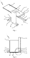
- figure 1 shows an embodiment of a lift 1 according to the invention.
- the lift 1 has a chassis 2 and a platform 3 that can be lifted relative to the chassis 2 .
- the chassis 2 comprises a U-shaped base frame 4 with two freely ending legs 5, 6 and a connecting leg 7 which connects the two freely ending legs 5, 6.
- the lift 1 has a lifting column 10 with a lifting drive, not shown in detail.
- the lifting column 10 is arranged in the area of one of the two freely ending legs 5 , 6 .
- the platform 3 is dimensioned and arranged in such a way that it - viewed in projection onto the base frame 4 - is located within the free space 11 delimited by the base frame 4 and optionally only in the area of the open end of the U-shaped base frame 4 with a End section 12 protrudes beyond this.
- a ramp 13 is provided in the area of the end section 12 .
- a ramp 15 is arranged at the end portion 14 of the platform 3, which is opposite the end portion 12, a ramp 15 is arranged.
- the ramp 15 In the in the Figures 1 to 4 shown driving position of the lift 1, the ramp 15 is shown in its folded-up position. However, it can be unfolded in an upper loading position of the lift 1, as shown in figure 7 shown.
- the lift 1 is shown in its driving position.
- the platform 3 In the driving position, the platform 3 is aligned essentially parallel to the floor 9 and an underside 16 of the platform 3 has a predetermined minimum distance 17 from the floor level 18 .
- the minimum distance 17 is selected so that there is sufficient ground clearance between the platform 3 and the floor 9 and the lift 1 can also be moved over small obstacles without the risk of the lift 1 touching down and/or damaging the platform 3 consists.
- the underside 16 of the platform 3 in the driving position can, for example, be approximately level with the underside 19 of the base frame 4 of the chassis 2 .
- a wheelchair user In the driving position, a wheelchair user would therefore have to overcome at least the minimum distance 17 in order to get from the floor level 18 to the platform 3 . He would therefore have to overcome a quite considerable level.
- one would have to sufficiently flat ramp to be arranged as an extension of the platform 3, so that driving onto the platform 3 would be possible without too great an incline.
- the platform 3 In the lift 1 according to the invention, however, the platform 3 can be specifically lowered into a lower loading position in order to make it easier to drive onto the platform 3 .
- the lower loading position is in the Figures 5 and 6 illustrated.
- the platform 3 is lowered further compared to the driving position, so that the distance between the underside 16 of the platform 3 and the floor level 18 is reduced compared to the minimum distance 17 .
- the distance can be reduced to zero or almost zero, so that a wheelchair user can drive onto the platform 3 via the ramp 13 in a substantially step-free manner.
- the fact that the distance can be reduced to such an extent is achieved in particular by the dimensioning and arrangement of the platform 3 .
- the platform is dimensioned and arranged in relation to the base frame 4 in such a way that it can be lowered into and even below the free space 11 defined by the base frame 4 .
- the end section 12, via which a wheelchair user can access the platform 3, is in the area of the open end of the U-shaped base frame 4. The height to be overcome is therefore not determined by the height of the base frame 4, but by the thickness of the platform 3.
- the lift 1 is shown in its upper loading position, in which the platform 3 is raised relative to the driving position, so that entry and exit at a level that is higher than the ground level 18 is possible. Entry and exit takes place via the end section 14 and the ramp 15 arranged in this area. a wheelchair user can drive over the platform 3 in the crossing direction 20 without a change of direction being required for boarding or alighting.
- the ramp 15 can act as a roll-off safety device.
- further safety elements can be provided for roll-off safety, in particular in the area of the end section 12 and in the side areas of the platform 3.
- a degree of freedom of rotation about a vertical axis of rotation is provided.
- the platform 3 z. B. together with the chassis 2 and the lifting column 10 arranged thereon are rotated about the vertical axis of rotation 21, as in figure 10 implied.
- the platform 3 In the rotary position, the platform 3 is lowered in relation to the chassis 2 to such an extent that a turntable 22, which is rotatably arranged on the underside 16 of the platform 3, is in contact with the floor 9 and the chassis 2 is even lifted off the floor 9, as in FIG figure 9 indicated by the distance 23. Due to the ground clearance achieved in this way, the platform 3 can be rotated about the vertical axis of rotation 21 together with the chassis 2 relative to the turntable 22 .
- the degree of rotational freedom can be used as follows: For a transfer of a wheelchair user from the platform to a vehicle, the lift 1 is placed in its driving position on the platform in such a way that the direction 20 of the platform 3 is oriented approximately parallel to the longitudinal direction of the platform. The lift 1 is then transferred to the lower loading position in which the wheelchair user on the ramp 13 z. B. can drive onto the platform 3 in the forward direction. In the next step, the lift 1 is transferred to the turning position. The platform 3 is rotated in the position shown in figure 10 shown, e.g. B. rotated counterclockwise by about 90 °.
- the orientation of the platform 3 changes relative to the platform, so that the crossing direction 20 is ultimately oriented approximately transversely to the longitudinal direction of the platform.
- the end section 14 with the ramp 15 now points in the direction of a platform edge and a vehicle standing there.
- the platform is now raised to the desired elevated level by the lifting drive.
- the wheelchair user can drive off the platform 3 in the overrun direction 20 and in particular further in the forward direction via the end section 14 and the ramp 15 and get into the vehicle.
- a vehicle can also be exited.
Landscapes
- Health & Medical Sciences (AREA)
- Public Health (AREA)
- Life Sciences & Earth Sciences (AREA)
- Animal Behavior & Ethology (AREA)
- General Health & Medical Sciences (AREA)
- Veterinary Medicine (AREA)
- Vehicle Step Arrangements And Article Storage (AREA)
Abstract
Description
- Die Erfindung betrifft einen Hublift zum Heben von Rollstühlen insbesondere für einen Ein- und/oder Ausstieg in Fahrzeuge, z. B. an einem Bahnsteig, mit den Merkmalen des Oberbegriffs von Anspruch 1.
- Um Rollstuhlfahrern z. B. den Einstieg in ein Schienenfahrzeug zu erleichtern, kommen Hublifte zum Einsatz, die auf dem Bahnsteig frei verfahren und im Bereich vor einer Fahrzeugtür positioniert werden können. Der Hublift weist eine Plattform auf, die gegenüber seinem Fahrgestell hubbeweglich ist. In seiner untersten Stellung kann ein Rollstuhlfahrer vom Bahnsteig auf die Plattform gelangen. Um eine Stufe zwischen dem Bahnsteig und der Plattform zu überbrücken, wird üblicherweise eine Rampe ausgeklappt, so dass der Rollstuhlfahrer nahezu stufenfrei und ohne eine zu große Steigung auf die Plattform gelangen kann. Anschließend wird die Plattform in eine obere Position bewegt, in der sich die Plattform in etwa auf Höhe des Fahrzeugbodens befindet. Um einen Abstand zwischen der Plattform und dem Fahrzeug zu überbrücken, ist eine weitere Rampe vorgesehen, die ausgeklappt werden kann, so dass der Rollstuhlfahrer von der Plattform über die Rampe in das Fahrzeug wechseln kann.
- Derartige Hublifte sind z. B. aus den Dokumenten
DE 4 342 373 A1 undWO 2007/068126 A1 bekannt. Die dort offenbarten Hublifte umfassen einen U-förmigen Stützrahmen zur Abstützung gegenüber dem Boden, eine seitlich an einem mittleren Schenkel des Stützrahmens angeordnete Hubsäule und eine hubbewegliche Plattform. Die Längsrichtung der Plattform verläuft parallel zum mittleren Schenkel des Stützrahmens und erstreckt sich über die beiden von dem mittleren Schenkel abragenden weiteren Schenkel des Stützrahmens, wobei ein Rollstuhlfahrer in Vorwärtsrichtung auf die Plattform auf- und auch wieder von ihr abfahren kann. Um ein stufenfreies Auf- bzw. Abfahren zu ermöglichen, ist an der Plattform eine verschwenkbare Rampe vorgesehen. - Daneben sind Hublifte bekannt, deren hubbewegliche Plattform lediglich von einer Seite befahren werden kann. D. h. ein Rollstuhlfahrer kann z. B. in Vorwärtsrichtung auf die Plattform auffahren und die Plattform kann dann auf das Fahrzeugniveau angehoben werden. Um in das Fahrzeug zu gelangen, muss der Rollstuhlfahrer in Rückwärtsrichtung von der Plattform abfahren. Ein derartiger Hublift ist z. B. aus dem Dokument
DE 299 16 236 U1 bekannt. - Aufgabe der Erfindung ist es, einen Hublift so weiterzuentwickeln, dass die Ein- bzw. Ausstiegszeiten und/oder der Platzbedarf bei der Benutzung verringert werden kann, insbesondere ohne Komforteinschränkungen für den Rollstuhlfahrer und/oder das Bedienpersonal.
- Die erfindungsgemäße Aufgabe wird gelöst durch einen Hublift mit den Merkmalen des unabhängigen Anspruchs 1.
- Erfindungsgemäß wurde erkannt, der Einsatz von ausklappbaren Rampen bei Hubliften für einen möglichst komfortablen Ein-/Ausstieg von Rollstuhlfahrern ein limitierender Faktor ist. Zum einen können derartige Hublifte nur auf ausreichend breiten Bahnsteigen eingesetzt werden, bei denen auch bei ausgeklappter Rampe in Verlängerung der Rampe ausreichend viel Platz für einen Rollstuhlfahrer vorhanden ist. Zum anderen verzögern sich durch das Aus- und Einklappen der Rampe die Ein- und Ausstiegszeiten. Der Erfindung liegt die Erkenntnis zugrunde, dass auf eine solche Rampe verzichtet werden kann, ohne dass es zu Komforteinbußen kommt. Erfindungsgemäß ist dazu vorgesehen, dass eine Plattform eines Hublifts aus einer normalen Fahrstellung, in der eine Unterseite der Plattform einen Mindestabstand zum Bodenniveau aufweist, so dass der Hublift frei über den Bahnsteig bewegt werden kann, z. B. um ihn passend vor einer Fahrzeugtür zu platzieren, gezielt abgesenkt werden kann, so dass ein Rollstuhlfahrer vom Bodenniveau aus im Wesentlichen stufenfrei auf die Plattform auffahren oder von dieser abfahren kann.
- Ein erfindungsgemäßer Hublift kann insbesondere für den Einsatz an einem Bahnsteig vorgesehen sein, um Rollstuhlfahrern einen Ein- bzw. Ausstieg von dem Bahnsteig in ein Fahrzeug zu ermöglichen, dessen Bodenniveau vom Bodenniveau des Bahnsteigs verschieden ist. Daneben kann ein solcher Hublift aber auch an anderen Orten zum Einsatz kommen, z. B. an Veranstaltungsorten, für die zumindest vorübergehend eine flexible Barrierefreiheit geschaffen werden soll.
- Um den Hublift flexibel auf einer Fläche bewegen zu können, weist dieser ein Fahrgestell auf. Das Fahrgestell kann insbesondere Rollen bzw. Räder umfassen, so dass der Hublift möglichst leicht relativ zum Boden verfahren werden kann. Gemäß einer einfach gehaltenen Ausführung lässt sich der Hublift rein manuell verfahren. Es kann aber auch eine Motorunterstützung zum Verfahren des Hublifts vorgesehen sein.
- Ferner weist der Hublift eine Plattform auf, die relativ zu dem Fahrgestell hubbeweglich ist. Im Betrieb des Hublifts kann ein Rollstuhlfahrer auf die Plattform auffahren. Durch eine Hubbewegung wird die Plattform so weit angehoben bzw. abgesenkt, dass der Rollstuhlfahrer auf dem gewünschten Niveau wieder von der Plattform abfahren kann.
- Erfindungsgemäß weist der Hublift mindestens drei Stellungen auf: eine Fahrstellung, eine untere Ladestellung und eine obere Ladestellung.
- Die Fahrstellung zeichnet sich dadurch aus, dass eine Unterseite der Plattform einen vorgegebenen Abstand zum Bodenniveau aufweist und dass der Hublift relativ zum Boden verfahren werden kann. Ein vorgegebener Mindestabstand der Plattform zum Bodenniveau ist dabei wichtig, um die nötige Bodenfreiheit bereitzustellen, so dass z. B. auch Bodenwellen und kleinere Hindernisse von dem Hublift überfahren werden können, ohne dass die Gefahr eines Aufsetzens oder einer Beschädigung der Plattform besteht. Gleichzeitig darf der Abstand der Plattform zum Bodenniveau in der Fahrstellung nicht zu groß sein. Je größer der Abstand ist, desto instabiler lässt sich der Hublift verfahren aufgrund der damit einhergehenden Schwerpunktsverlagerung in vertikaler Richtung nach oben.
- Bei den aus dem Stand der Technik bekannten Hubliften dient die Fahrstellung gleichzeitig als die Stellung, in der ein Rollstuhlfahrer vom Bodenniveau aus auf die Plattform auffahren bzw. von der Plattform auf das Bodenniveau abfahren kann. Zur Überbrückung des vorgegebenen Mindestabstands der Plattform zum Bodenniveau ist dabei eine Rampe vorgesehen, die ausklappbar an der Plattform angeordnet ist.
- Erfindungsgemäß ist demgegenüber die untere Ladestellung dafür vorgesehen, dass ein Rollstuhlfahrer von dem Bodenniveau aus auf die Plattform auffahren bzw. von der Plattform auf das Bodenniveau abfahren kann. Dabei ist die Plattform in der unteren Ladestellung gezielt gegenüber der Fahrstellung abgesenkt, so dass der Abstand zwischen der Unterseite der Plattform und dem Bodenniveau möglichst minimiert ist. Durch den reduzierten Abstand zwischen der Plattform und dem Bodenniveau kann ein Rollstuhlfahrer ohne Komforteinbußen auch ohne eine Rampe auf die Plattform auf- bzw. von dieser abfahren. Entsprechend reduziert sich der Zeitaufwand, der für das Aus- und wieder Einklappen der Rampe bei den aus dem Stand der Technik bekannten Hubliften erforderlich ist. Ferner sinkt auch der Platzbedarf des Hublifts, da kein über die Plattform hinausgehender Freiraum für eine Rampe vorhanden sein muss. D. h. ein erfindungsgemäßer Hublift kann auch in engen Bereichen eingesetzt werden.
- Damit ein Rollstuhlfahrer auf einem gegenüber dem Bodenniveau erhöhten Niveau von der Plattform abfahren bzw. auf diese auffahren kann, wird die Plattform in die obere Ladestellung bewegt. In dieser ist die Plattform gegenüber der Fahrstellung angehoben für einen Ein- bzw. Ausstieg in dem gegenüber dem Bodenniveau erhöhten Niveau. Dabei ist ein Höhenunterschied zwischen der Plattform und z. B. dem Bodenniveau eines Fahrzeugs im Idealfall vollständig eliminiert.
- Im Folgenden wird im Regelfall von einer Nutzungssituation des erfindungsgemäßen Hublifts ausgegangen, bei der ein Rollstuhlfahrer in einer unteren Ladestellung auf die Plattform auffährt und in der oberen Ladestellung wieder von der Plattform abfährt, z. B. um von einem Bahnsteig in ein Fahrzeug mit gegenüber dem Bodenniveau erhöhtem Niveau einzusteigen. Auch wenn dies nicht gesondert erläutert wird, gelten die Erläuterungen entsprechend für die umgekehrte Nutzungssituation, in der ein Rollstuhlfahrer in einer oberen Ladestellung auf die Plattform auffährt und in der unteren Ladestellung wieder von der Plattform abfährt, z. B. um aus einem Fahrzeug mit einem gegenüber dem Bodenniveau erhöhtem Niveau auszusteigen und auf den Bahnsteig zu gelangen.
- Für ein möglichst einfaches Auf- und Abfahren von der Rampe weist die Plattform gemäß einer erfindungsgemäßen Ausführungsform zwei in Überfahrrichtung gegenüberliegende Endabschnitte auf, wobei die Plattform von jedem der beiden Endabschnitte befahrbar ist. Insbesondere ist so eine Art Durchladung möglich. D. h. ein Rollstuhlfahrer kann über einen Endabschnitt in Vorwärtsrichtung auf die Plattform auffahren und kann auch in Vorwärtsrichtung über den gegenüberliegenden Endabschnitt wieder von der Plattform abfahren.
- In der unteren Ladestellung ist ein Abstand zwischen der befahrbaren Fläche der Plattform und dem Bodenniveau weitgehend minimiert. Da die Plattform eine gewisse Stärke aufweisen muss, um die nötige Stabilität bereitzustellen, kann der Abstand jedoch nicht auf Null reduziert werden. Um einen weitgehend stufenfreien Ein- bzw. Ausstieg zu ermöglichen, weist die Plattform daher bei einer erfindungsgemäßen Ausführungsform an zumindest einem der Endabschnitte zum Auffahren auf die Plattform bzw. zum Abfahren von der Plattform eine Auffahrschräge auf. Die Auffahrschräge kann dabei insbesondere integral von der Plattform ausgebildet sein, z. B. indem die Plattform zu dem Endabschnitt hin abgeflacht ist. Ein Neigungswinkel der Auffahrschräge ist dabei vorzugsweise nicht größer als 6°.
- In der oberen Ladestellung ist ein Höhenunterschied zwischen der Plattform und z. B. dem Bodenniveau eines Fahrzeugs im Idealfall vollständig eliminiert. Ein verbleibender lateraler und/oder vertikaler Abstand zwischen der Plattform und dem Fahrzeug kann durch eine an der Plattform vorgesehene Rampe überbrückt werden. Die Rampe kann dabei ausklappbar oder ausfahrbar an der Plattform angeordnet sein. So kann die Rampe gezielt für ein Auffahren auf die Rampe bzw. Abfahren von der Rampe ausgeklappt oder ausgefahren werden. Im eingeklappten bzw. eingefahrenen Zustand ist die Rampe weitgehend verstaut, so dass diese möglichst wenig Raum in Anspruch nimmt. Insbesondere wenn die Rampe ausklappbar an der Plattform angeordnet ist, kann diese in ihrer hochgeklappten Stellung auch als Abrollsicherung für einen Rollstuhlfahrer dienen. Alternativ oder zusätzlich können andere Sicherungselement zur Abrollsicherung vorgesehen sein, z. B. ein Bügel, eine Kette, ein Band o. ä.
- Gemäß einer Ausführungsform weist das Fahrgestell einen im Wesentlichen U-förmigen Grundrahmen auf. Dieser umfasst zwei frei endende Schenkel sowie einen diese beiden Schenkel verbindenden Verbindungsschenkel auf. Der Grundrahmen ist im Wesentlichen in horizontaler Richtung orientiert und dient als Stützelement, über das sich der Hublift zumindest indirekt über etwaige Rollen oder Räder an dem Boden abstützt. Die Plattform ist insbesondere derart zu dem Grundrahmen positioniert und orientiert, dass die Plattform in der unteren Ladestellung in oder sogar bis unter einen von dem Grundrahmen begrenzten Freiraum abgesenkt ist. D. h. in der unteren Ladestellung ist ein Abstand zwischen der Unterseite der Plattform und dem Bodenniveau nicht dadurch begrenzt, dass ausreichend Platz für Teile des Grundrahmens verbleiben muss, die sich zwischen dem Bodenniveau und der Plattform unterhalb der Plattform befinden. Vielmehr lässt sich der Grundrahmen in oder sogar bis unter den von dem U-förmigen Grundrahmen definierten Freiraum absenken. Im Idealfall kann die Plattform bis auf das Bodenniveau abgesenkt werden.
- In der unteren Ladestellung kann die Plattform derart zu dem Grundrahmen orientiert sein, dass ein Endabschnitt zum Auffahren auf die Plattform von dem Bodenniveau - in Projektion auf den Grundrahmen gesehen - zwischen den beiden frei endenden Schenkeln angeordnet ist. D. h. der Endabschnitt ist im Bereich des offenen Endes des U-förmigen Grundrahmens positioniert. Somit muss z. B. zum Auffahren auf die Plattform nicht der Grundrahmen überwunden werden. Entsprechend wird eine zu überwindende Höhe, um von dem Bodenniveau auf die Plattform zu gelangen, nicht durch die Höhe des Grundrahmens bestimmt. Vielmehr kann man direkt von dem Bodenniveau über den Endabschnitt der Plattform auf diese auffahren. Die zu überwindende Höhe wird somit im Wesentlichen durch die Stärke der Plattform und insbesondere den im Bereich des offenen Endes liegenden Endabschnitt bestimmt, welche vergleichsweise gering gehalten werden kann. Für einen möglichst stufenfreien Ein- bzw. Ausstieg kann im Bereich des Endabschnitts zum Befahren der Plattform eine Auffahrschräge vorgesehen sein.
- Wenn die Plattform ohne Richtungswechsel überfahrbar ist und der gegenüberliegende Endabschnitt z. B. zum Abfahren in der oberen Ladestellung dient, liegt dieser Endabschnitt gemäß der voranstehend genannten Ausführungsform in Projektion auf den Grundrahmen gesehen im Bereich des Verbindungsschenkels des Grundrahmens. Der Verbindungsschenkel begrenzt dabei prinzipiell die minimale Höhe, von der in der oberen Ladestellung von der Plattform abgefahren werden kann. Dies ist jedoch unkritisch, da das erhöhte Niveau im Regelfall deutlich über der Höhe des Grundrahmens liegt.
- Zum Ausführen der Hubbewegung kann eine Hubsäule mit einem Hubantrieb vorgesehen sein. Es kann sich dabei um einen manuell oder automatisch betätigten Hubantrieb handeln. Konkret kann es sich bei dem Hubantrieb um einen hydraulischen Antrieb oder einen Gurtantrieb handeln.
- Die Hubsäule mit dem Hubantrieb kann im Bereich eines der frei endenden Schenkel des Grundrahmens angeordnet sein. Insbesondere kann durch diese Anordnung erreicht werden, dass die Plattform ohne Richtungswechsel überfahren werden kann, wenn der Endabschnitt zum Befahren der Plattform vom Bodenniveau aus in der unteren Ladestellung im Bereich des offenen Endes des U-förmigen Grundrahmens liegt.
- Für eine möglichst gute Abstützung der Plattform kann neben der Hubsäule eine weitere Hubsäule mit einem weiteren Hubantrieb für die Hubbewegung der Plattform vorgesehen sein. Die weitere Hubsäule ist dabei insbesondere an dem anderen frei endenden Schenkel des Grundrahmens angeordnet, wodurch ein weitgehend symmetrischer Aufbau erreicht werden kann. Um eine möglichst gleichförmige Hubbewegung zu erreichen, kann der weitere Hubantrieb dabei mit dem Hubantrieb synchronisiert sein.
- Gemäß einer Ausführungsform ist die Plattform gegenüber dem Fahrgestell um eine vertikale Drehachse drehbar. Alternativ oder zusätzlich kann die Plattform gemeinsam mit dem Fahrgestell um eine vertikale Drehachse drehbar sein. Für den Einsatz an einem Bahnsteig ist es so insbesondere möglich, die Ausrichtung der Plattform in den verschiedenen Stellungen des Hublifts gezielt zu ändern.
- Konkret kann die Plattform in der oberen Ladestellung gegenüber der unteren Ladestellung um die vertikale Achse gedreht sein, z. B. um einen Winkel im Bereich von 80 bis 110° und insbesondere um einen Winkel im Bereich von 90°. Beispielsweise kann die Plattform in der unteren Ladestellung so orientiert sein, dass die Auffahrrichtung auf die Plattform parallel zur Bahnsteiglängsrichtung orientiert ist. In der oberen Ladestellung kann die Plattform demgegenüber um 90° gedreht sein, so dass die Abfahrrichtung von der Plattform quer zu der Bahnsteiglängsrichtung orientiert ist. So lässt sich einerseits erreichen, dass ein Rollstuhlfahrer die Plattform für den Ein- bzw. Ausstieg ohne Richtungswechsel relativ zur Plattform überfahren kann. Gleichzeitig ändert sich jedoch die Orientierung der Plattform z. B. relativ zum Bahnsteig. So kann ausgenutzt werden, dass in Längsrichtung des Bahnsteigs ausreichend viel Platz vorhanden ist und somit auch eine längere Auffahrschräge und/oder Rampen zum Auffahren auf die Plattform kein Problem darstellen.
- Zur Realisierung der Drehbarkeit um die vertikale Drehachse gibt es verschiedene Möglichkeiten. Insbesondere kann hierfür ein Drehlager vorgesehen sein. Gemäß einer Ausführungsform ist zum Drehen der Plattform um die vertikale Drehachse ein Drehkranz und/oder Drehteller vorgesehen. Wenn die Plattform gegenüber dem Fahrgestell drehbar ist, kann das Drehlager z. B. zwischen der Plattform und dem Fahrgestell angeordnet sein. Für eine gemeinsame Drehung der Plattform mit dem Fahrgestell kann der Drehkranz beispielsweise unter der Plattform und/oder an dem Fahrgestell angeordnet sein.
- In weiterer Ausgestaltung kann der Hublift eine Drehstellung aufweisen, in der die Unterseite der Plattform in vertikaler Richtung einen vorgegebenen Abstand zu dem Grundrahmen des Fahrgestells aufweist und in der die Plattform für eine Drehung um die vertikale Achse freigegeben ist. Demgegenüber kann eine Drehung der Plattform um die vertikale Drehachse z. B. in der unteren oder oberen Ladestellung verhindert sein. Beispielsweise kann dazu eine mechanische Arretierung sein oder eine entsprechende Steuerung vorgesehen sein.
- Wenn sich die Plattform relativ zu dem Grundrahmen drehen kann, ist der vorgegebene Abstand insbesondere dadurch vorgegeben, dass sich die Plattform in der Drehstellung oberhalb des Grundrahmens befindet und sich somit frei über diesen hinweg drehen kann. Dabei ist der vorgegebene Abstand zu dem Grundrahmen vorzugsweise möglichst gering, so dass auch trotz der angehobenen Plattform eine gute Stabilität gegeben ist.
- Wenn sich die Plattform gemeinsam mit der Plattform dreht, kann der vorgegebene Abstand beispielsweise dadurch bestimmt sein, wie weit die Plattform abgesenkt werden muss, so dass ein an der Unterseite der Plattform drehbar angeordneter Drehteller mit dem Boden in Kontakt kommt, so dass über den Drehteller das Gewicht des Hublifts an dem Boden abgestützt wird. Bei einer weiteren Hubbewegung wird nicht die Plattform weiter abgesenkt, sondern der Grundrahmen gegenüber der Plattform und gegenüber dem Boden angehoben, bis eine gewünschte Bodenfreiheit erreicht ist. In der so erreichten Drehstellung kann die Plattform gemeinsam mit dem Grundrahmen gegenüber dem Drehteller um die vertikale Drehachse gedreht werden.
- Wenn die Plattform um eine vertikale Drehachse drehbar ist und das Drehgestell einen U-förmigen Grundrahmen aufweist, kann eine besondere Positionierung der Hubsäule relativ zu dem Grundrahmen vorgesehen sein. Konkret kann die Hubsäule im Bereich der Hälfte und bevorzugt des Drittels des frei endenden Schenkels des Grundrahmens angeordnet sein, in dem sich dessen freies Ende befindet. Die vertikale Drehachse liegt dabei - in Projektion auf den Grundrahmen gesehen - im Wesentlichen auf gleicher Höhe wie die Hubsäule und im Wesentlichen zwischen den beiden frei endenden Schenkeln. Durch diese Anordnung wird einerseits ein stabiler Aufbau erreicht, bei der die vertikale Drehachse einen möglichst geringen Abstand zu der Hubsäule aufweist. Andererseits ist die vertikale Drehachse so positioniert, dass bei der Drehung das in Bezug auf die vertikale Drehachse gesehen längere Ende der Plattform auf ein Fahrzeug zu gedreht wird und somit in der oberen Ladestellung zum Abfahren von der Plattform in das Fahrzeug genutzt werden kann. Somit kann in der gedrehten Stellung durch die Plattform ein größerer Abstand zu dem Fahrzeug überbrückt werden.
- Insbesondere wenn die Plattform drehbar ist, kann es für Personal schwierig sein, den Hublift so zu positionieren, dass der Endabschnitt der Plattform, über den diese in der oberen Ladestellung verlassen werden kann, fluchtend z. B. mit einem Fahrzeugeinstieg angeordnet ist. Daher ist gemäß einer Ausführungsform eine Positionierhilfe vorgesehen. Die Positionierhilfe zeigt die Position des Endabschnitts der Plattform zum Auffahren auf die bzw. zum Abfahren von der Plattform in der oberen Ladestellung an. Die Position wird dabei vorzugsweise zumindest in der Fahrstellung und/oder auf besondere Aktivierung durch Bedienpersonal mittels der Positionierhilfe angezeigt.
- Die Position kann in Bezug auf eine oder auch mehrere Raumrichtungen angezeigt werden. Für einen Ein- bzw. Ausstieg in ein Fahrzeug kann z. B. in Einstiegs- bzw. Ausstiegsrichtung angezeigt werden, wo sich der Endabschnitt zum Befahren bzw. Verlassen der Plattform in der oberen Ladestellung befinden wird. Konkret kann dazu mittels einer Lichtprojektion auf die Fahrzeugwandung die Position des Endabschnitts in Projektion auf die Fahrzeugwandung angezeigt werden. Z. B. kann die Positionierhilfe zwei Lichtquellen umfassen, mit denen jeweils ein Lichtpunkt erzeugt wird. Die Lichtpunkte können dabei die seitliche Erstreckung des Endabschnitts zum Befahren bzw. Verlassen der Plattform relativ zu dem Fahrzeug visualisieren. Auch kann eine Lichtprojektion auf den Boden vorgesehen sein, um anzuzeigen, wo der Endabschnitt relativ zum Boden endet, und so den Abstand zum Fahrzeug zu visualisieren. Alternativ oder zusätzlich kann es sich bei der Positionierhilfe um eine einfache Markierung, z. B. hervorgehobene farbige Streifen an der Plattform oder dem Fahrgestell handeln.
- Vorteilhafte Weiterbildungen der Erfindung ergeben sich aus den Ansprüchen, der Beschreibung und den Zeichnungen. Die in der Beschreibung genannten Vorteile von Merkmalen und von Kombinationen mehrerer Merkmale sind lediglich beispielhaft und können alternativ oder kumulativ zur Wirkung kommen, ohne dass die Vorteile zwingend von erfindungsgemäßen Ausführungsformen erzielt werden müssen. Die in den Ansprüchen und der Beschreibung genannten Merkmale sind bezüglich ihrer Anzahl so zu verstehen, dass genau diese Anzahl oder eine größere Anzahl als die genannte Anzahl vorhanden ist, ohne dass es einer expliziten Verwendung des Begriffs "mindestens" bedarf. Wenn also beispielsweise von einer Positionierhilfe die Rede ist, so ist dies so zu verstehen, dass genau eine Positionierhilfe, zwei Positionierhilfen oder mehrere Positionierhilfen vorhanden sind. Diese Merkmale können durch andere Merkmale ergänzt werden oder die einzigen Merkmale sein, aus denen das jeweilige Erzeugnis besteht. Die in den Ansprüchen enthaltenen Bezugszeichen stellen keine Beschränkung des Umfangs der durch die Ansprüche geschützten Gegenstände dar. Sie dienen lediglich dem Zweck, die Ansprüche leichter verständlich zu machen.
- Weitere, die Erfindung verbessernde Maßnahmen werden nachstehend gemeinsam mit der Beschreibung bevorzugter Ausführungsbeispiele der Erfindung anhand der Figuren näher dargestellt. Es zeigt:
- Figur 1
- eine perspektivische Ansicht eines erfindungsgemäßen Hublifts in seiner Fahrstellung,
- Figur 2
- eine Draufsicht auf den Hublift gemäß
Figur 1 in seiner Fahrstellung, - Figur 3
- eine Seitenansicht des Hublifts gemäß
Figur 1 in seiner Fahrstellung, - Figur 4
- ein Detail von
Figur 3 , - Figur 5
- eine Seitenansicht des Hublifts gemäß
Figur 1 in seiner unteren Ladestellung, - Figur 6
- ein Detail von
Figur 5 , - Figur 7
- eine perspektivische Ansicht des Hublifts gemäß
Figur 1 in seiner oberen Ladestellung, - Figur 8
- eine Seitenansicht eines erfindungsgemäßen Hublifts in seiner Drehstellung,
- Figur 9
- ein Detail von
Figur 8 , - Figur 10
- den Hublift gemäß
Figur 8 in einer Draufsicht. -
Figur 1 zeigt eine Ausführungsform eines erfindungsgemäßen Hublifts 1. Der Hublift 1 weist ein Fahrgestell 2 und ein gegenüber dem Fahrgestell 2 hubbewegliche Plattform 3 auf. - Das Fahrgestell 2 umfasst einen U-förmigen Grundrahmen 4 mit zwei frei endenden Schenkeln 5, 6 und einem Verbindungsschenkel 7, der die beiden frei endenden Schenkel 5, 6 verbindet. An dem Grundrahmen 4 sind insgesamt vier Räder 8 angeordnet, durch die der Hublift 1 relativ zum Boden 9 flexibel verfahren werden kann.
- Um die Plattform 3 gegenüber dem Fahrgestell 2 anheben und absenken zu können, weist der Hublift 1 eine Hubsäule 10 mit einem nicht näher dargestellten Hubantrieb auf. Die Hubsäule 10 ist im Bereich eines der beiden frei endenden Schenkel 5, 6 angeordnet.
- Wie insbesondere aus
Figur 2 ersichtlich ist, ist die Plattform 3 so dimensioniert und angeordnet, dass sich diese - in Projektion auf den Grundrahmen 4 gesehen - innerhalb des von dem Grundrahmen 4 begrenzten Freiraums 11 befindet und optional lediglich im Bereich des offenen Endes des U-förmigen Grundrahmens 4 mit einem Endabschnitt 12 über diesen übersteht. Im Bereich des Endabschnitts 12 ist eine Auffahrschräge 13 vorgesehen. - An dem Endabschnitt 14 der Plattform 3, der dem Endabschnitt 12 gegenüberliegt, ist eine Rampe 15 angeordnet. In der in den
Figuren 1 bis 4 gezeigten Fahrstellung des Hublifts 1 ist die Rampe 15 in ihrer hochgeklappten Stellung gezeigt. Sie kann jedoch in einer oberen Ladestellung des Hublifts 1 ausgeklappt werden, wie inFigur 7 gezeigt. - In den
Figuren 1 bis 4 ist der Hublift 1 in seiner Fahrstellung gezeigt. In der Fahrstellung ist die Plattform 3 im Wesentlichen parallel zu dem Boden 9 ausgerichtet und eine Unterseite 16 der Plattform 3 weist einen vorgegebenen Mindestabstand 17 zum Bodenniveau 18 auf. Der Mindestabstand 17 ist dabei so gewählt, dass genügend Bodenfreiheit zwischen der Plattform 3 und dem Boden 9 gegeben ist und der Hublift 1 auch über kleinere Hindernisse bewegt werden kann, ohne dass die Gefahr eines Aufsetzens des Hublifts 1 und/oder einer Beschädigung der Plattform 3 besteht. Wie in denFiguren 3 und 4 gezeigt, kann die Unterseite 16 der Plattform 3 in der Fahrstellung beispielsweise in etwa auf einer Höhe mit der Unterseite 19 des Grundrahmens 4 des Fahrgestells 2 liegen. - In der Fahrstellung müsste ein Rollstuhlfahrer somit mindestens den Mindestabstand 17 überwinden, um von dem Bodenniveau 18 auf die Plattform 3 zu gelangen. Er müsste somit eine durchaus beachtliche Stufe überwinden. Alternativ müsste eine ausreichend flache Rampe in Verlängerung der Plattform 3 angeordnet werden, damit ein Auffahren auf die Plattform 3 ohne allzu große Steigung möglich wäre. Bei dem erfindungsgemäßen Hublift 1 kann die Plattform 3 jedoch gezielt in eine untere Ladestellung abgesenkt werden, um ein Auffahren auf die Plattform 3 zu erleichtern.
- Die untere Ladestellung ist in den
Figuren 5 und 6 veranschaulicht. In der unteren Ladestellung ist die Plattform 3 gegenüber der Fahrstellung weiter abgesenkt, so dass der Abstand zwischen der Unterseite 16 der Plattform 3 und dem Bodenniveau 18 im Vergleich zu dem Mindestabstand 17 reduziert ist. Im Idealfall kann der Abstand auf Null oder nahezu Null reduziert werden, so dass ein Rollstuhlfahrer im Wesentlichen stufenfrei über die Auffahrschräge 13 auf die Plattform 3 auffahren kann. Dass der Abstand so weit reduziert werden kann, wird insbesondere durch die Dimensionierung und Anordnung der Plattform 3 erreicht. Die Plattform ist dazu in Bezug auf den Grundrahmen 4 so dimensioniert und angeordnet, dass sie in und sogar bis unter den Freiraum 11, der durch den Grundrahmen 4 definiert ist, abgesenkt werden kann. Dabei liegt der Endabschnitt 12, über den ein Rollstuhlfahrer auf die Plattform 3 gelangen kann, im Bereich des offenen Endes des U-förmigen Grundrahmens 4. Die zu überwindende Höhe wird somit nicht durch die Höhe des Grundrahmens 4 bestimmt, sondern durch die Stärke der Plattform 3. - In
Figur 7 ist der Hublift 1 in seiner oberen Ladestellung gezeigt, in der die Plattform 3 gegenüber der Fahrstellung angehoben ist, so dass ein Ein- bzw. Ausstieg auf einem gegenüber dem Bodenniveau 18 erhöhten Niveau möglich ist. Der Ein- bzw. Ausstieg erfolgt dabei über den Endabschnitt 14 und die in diesem Bereich angeordnete Rampe 15. D. h. ein Rollstuhlfahrer kann die Plattform 3 in Überfahrrichtung 20 überfahren, ohne dass für einen Einstiegs- bzw. Ausstiegsvorgang ein Richtungswechsel erforderlich ist. - Wenn die Rampe 15 hochgeklappt ist, kann diese als Abrollsicherung fungieren. Zusätzlich können weitere, in den Figuren nicht dargestellte Sicherungselemente zur Abrollsicherung vorgesehen sein, insbesondere im Bereich des Endabschnitts 12 sowie in den Seitenbereichen der Plattform 3.
- Gemäß einer Ausführungsform der Erfindung ist ein Drehfreiheitsgrad um eine vertikale Drehachse vorgesehen. Konkret kann die Plattform 3 z. B. gemeinsam mit dem Fahrgestell 2 sowie der daran angeordneten Hubsäule 10 um die vertikale Drehachse 21 gedreht werden, wie in
Figur 10 angedeutet. Für eine Drehung um die vertikale Drehachse 21 wird der Hublift 1 in ein in denFiguren 8 und9 näher gezeigte Drehstellung überführt. In der Drehstellung ist die Plattform 3 gegenüber dem Fahrgestell 2 so weit abgesenkt, dass ein an der Unterseite 16 der Plattform 3 drehbar angeordneter Drehteller 22 in Kontakt mit dem Boden 9 ist und das Fahrgestell 2 sogar von dem Boden 9 abgehoben ist, wie inFigur 9 durch den Abstand 23 angedeutet. Durch die so erreichte Bodenfreiheit kann die Plattform 3 gemeinsam mit dem Fahrgestell 2 gegenüber dem Drehteller 22 um die vertikale Drehachse 21 gedreht werden. - Der Drehfreiheitsgrad kann folgendermaßen genutzt werden: Für einen Transfer eines Rollstuhlfahrers vom Bahnsteig in ein Fahrzeug wird der Hublift 1 in seiner Fahrstellung so auf dem Bahnsteig platziert, dass die Überfahrrichtung 20 der Plattform 3 in etwa parallel zur Längsrichtung des Bahnsteigs orientiert ist. Der Hublift 1 wird dann in die untere Ladestellung überführt, in der der Rollstuhlfahrer über die Auffahrschräge 13 z. B. in Vorwärtsrichtung auf die Plattform 3 auffahren kann. Im nächsten Schritt wird der Hublift 1 in die Drehstellung überführt. Die Plattform 3 wird in der Drehstellung, wie in
Figur 10 dargestellt, z. B. gegen den Uhrzeigersinn um ca. 90° gedreht. Infolge der Drehung ändert sich die Orientierung der Plattform 3 relativ zu dem Bahnsteig, so dass die Überfahrrichtung 20 letztlich in etwa quer zur Bahnsteiglängsrichtung orientiert ist. Der Endabschnitt 14 mit der Rampe 15 weist nun in Richtung eines Bahnsteigrands und zu einem dort stehenden Fahrzeug hin. Die Plattform wird nun durch den Hubantrieb auf das gewünschte erhöhte Niveau angehoben. Wenn die obere Ladestellung erreicht ist, kann der Rollstuhlfahrer in Überfahrrichtung 20 und insbesondere weiterhin in Vorwärtsrichtung über den Endabschnitt 14 und die Rampe 15 von der Plattform 3 abfahren und in das Fahrzeug gelangen. - In umgekehrter Weise kann auch ein Ausstieg aus einem Fahrzeug erfolgen.
-
- 1
- Hublift
- 2
- Fahrgestell
- 3
- Plattform
- 4
- Grundrahmen
- 5
- Schenkel
- 6
- Schenkel
- 7
- Verbindungsschenkel
- 8
- Rad
- 9
- Boden
- 10
- Hubsäule
- 11
- Freiraum
- 12
- Endabschnitt
- 13
- Auffahrschräge
- 14
- Endabschnitt
- 15
- Rampe
- 16
- Unterseite
- 17
- Abstand
- 18
- Bodenniveau
- 19
- Unterseite
- 20
- Überfahrrichtung
- 21
- Drehachse
- 22
- Drehteller
- 23
- Abstand
Claims (15)
- Hublift (1) zum Heben von Rollstühlen, insbesondere für einen Ein- und/oder Ausstieg in Fahrzeuge, z. B. an einem Bahnsteig, mit- einem Fahrgestell (2) zum Verfahren des Hublifts (1) relativ zum Boden (9) und- einer relativ zu dem Fahrgestell (2) hubbeweglichen Plattform (3),dadurch gekennzeichnet, dass
der Hublift (1) mindestens drei Stellungen aufweist:- eine Fahrstellung, in der eine Unterseite (16) der Plattform (3) einen vorgegebenen Abstand (17) zum Bodenniveau (18) aufweist und in der der Hublift (1) relativ zu dem Boden (9) verfahrbar ist,- eine obere Ladestellung, in der die Plattform (3) gegenüber der Fahrstellung angehoben ist für einen Ein- und/oder Ausstieg auf einem gegenüber dem Bodenniveau (18) erhöhten Niveau, und- eine untere Ladestellung, in der die Plattform (3) gegenüber der Fahrstellung abgesenkt ist für einen Ein- und/oder Ausstieg von dem Bodenniveau (18). - Hublift (1) nach Anspruch 1,
dadurch gekennzeichnet, dass
die Plattform (3) zwei in Überfahrrichtung (20) gegenüberliegende Endabschnitte (12, 14) aufweist, wobei die Plattform (3) von jedem der beiden Endabschnitte (12, 14) befahrbar ist. - Hublift (1) nach einem der vorhergehenden Ansprüche,
dadurch gekennzeichnet, dass
an einem der Endabschnitte (12, 14) der Plattform (3) zum Auffahren auf die bzw. Abfahren von der Plattform (3) eine Auffahrschräge (13) vorgesehen ist. - Hublift (1) nach einem der vorhergehenden Ansprüche,
dadurch gekennzeichnet, dass
an einem Endabschnitt (12, 14) der Plattform (3) zum Auffahren auf die bzw. Abfahren von der Plattform (3) eine ausklappbare und/oder ausfahrbare Rampe (15) angeordnet ist. - Hublift (1) nach einem der vorhergehenden Ansprüche,
dadurch gekennzeichnet, dass
das Fahrgestell (2) einen im Wesentlichen U-förmigen Grundrahmen (4) mit zwei frei endenden Schenkeln (5, 6) und einem die beiden Schenkel (5, 6) verbindenden Verbindungsschenkel (7) aufweist, wobei die Plattform (3) derart zu dem Grundrahmen (4) positioniert und orientiert ist, dass die Plattform (3) in der unteren Ladestellung in oder bis unter einen von dem Grundrahmen (4) begrenzten Freiraum (11) abgesenkt ist. - Hublift (1) nach Anspruch 5,
dadurch gekennzeichnet, dass
die Plattform (3) in der unteren Ladestellung zum Grundrahmen (4) derart orientiert ist, dass einer der Endabschnitte (12, 14) der Plattform (3) zum Auffahren auf die bzw. Abfahren von der Plattform (3) in Projektion auf den Grundrahmen (4) zwischen den beiden frei endenden Schenkeln (5, 6) angeordnet ist. - Hublift (1) nach Anspruch 5 oder 6,
dadurch gekennzeichnet, dass
eine Hubsäule (10) mit einem Hubantrieb für die Hubbewegung der Plattform (3) im Bereich eines der frei endenden Schenkeln (5, 6) des Grundrahmens (4) angeordnet ist. - Hublift (1) nach Anspruch 7,
dadurch gekennzeichnet, dass
eine weitere Hubsäule (10) mit einem weiteren Hubantrieb für die Hubbewegung der Plattform (3) im Bereich des anderen frei endenden Schenkels (5, 6) des Grundrahmens (4) angeordnet ist. - Hublift (1) nach Anspruch 8,
dadurch gekennzeichnet, dass
der weitere Hubantrieb mit dem Hubantrieb synchronisiert ist. - Hublift (1) nach einem der vorhergehenden Ansprüche,
dadurch gekennzeichnet, dass
die Plattform (3) gegenüber dem Fahrgestell (2) oder die Plattform (3) gemeinsam mit dem Fahrgestell (2) um eine vertikale Drehachse (21) drehbar ist. - Hublift (1) nach Anspruch 10,
dadurch gekennzeichnet, dass
die Plattform (3) in der oberen Ladestellung gegenüber der unteren Ladestellung um die vertikale Drehachse (21) gedreht ist, insbesondere um einen Winkel zwischen 80 und 110°. - Hublift (1) nach Anspruch 10 oder 11,
dadurch gekennzeichnet, dass
zwischen der Plattform (3) und dem Fahrgestell (2) und/oder an der Plattform (3) ein Drehkranz und/oder ein Drehteller (22) vorgesehen ist zum Drehen der Plattform (3) um die vertikale Drehachse (21). - Hublift (1) nach einem der Ansprüche 10 bis 12,
dadurch gekennzeichnet, dass
der Hublift (1) eine Drehstellung aufweist, in der die Plattform (3) in vertikaler Richtung einen vorgegebenen Abstand zum Grundrahmen (4) des Fahrgestells (2) aufweist und in der die Plattform (3) für eine Drehung um die vertikale Drehachse (21) freigegeben ist. - Hublift (1) nach einem der Ansprüche 10 bis 13 in Rückbeziehung auf Anspruch 8,
dadurch gekennzeichnet, dass- die Hubsäule (10) im Bereich der Hälfte und insbesondere des Drittels des frei endenden Schenkels (5, 6) angeordnet ist, in der/dem sich sein freies Ende befindet, und- die vertikale Drehachse (21) - in Projektion auf den U-förmigen Grundrahmen (4) des Fahrgestells (2) - im Wesentlichen auf Höhe der Hubsäule (10) und im Wesentlichen mittig zwischen den beiden frei endenden Schenkeln (5, 6) positioniert ist. - Hublift (1) nach einem der vorhergehenden Ansprüche,
dadurch gekennzeichnet, dass
eine Positionierhilfe vorgesehen ist zum Anzeigen der Position eines/des Endabschnitts (12, 14) der Plattform (3) zum Auffahren auf die bzw. Abfahren von der Plattform (3) in der oberen Ladestellung, wobei die Position mit der Positionierhilfe insbesondere in Form einer Lichtprojektion anzeigbar ist.
Priority Applications (1)
| Application Number | Priority Date | Filing Date | Title |
|---|---|---|---|
| EP20208273.1A EP4000571B8 (de) | 2020-11-18 | 2020-11-18 | Hublift zum heben von rollstühlen |
Applications Claiming Priority (1)
| Application Number | Priority Date | Filing Date | Title |
|---|---|---|---|
| EP20208273.1A EP4000571B8 (de) | 2020-11-18 | 2020-11-18 | Hublift zum heben von rollstühlen |
Publications (4)
| Publication Number | Publication Date |
|---|---|
| EP4000571A1 true EP4000571A1 (de) | 2022-05-25 |
| EP4000571C0 EP4000571C0 (de) | 2024-11-13 |
| EP4000571B1 EP4000571B1 (de) | 2024-11-13 |
| EP4000571B8 EP4000571B8 (de) | 2024-12-18 |
Family
ID=73475937
Family Applications (1)
| Application Number | Title | Priority Date | Filing Date |
|---|---|---|---|
| EP20208273.1A Active EP4000571B8 (de) | 2020-11-18 | 2020-11-18 | Hublift zum heben von rollstühlen |
Country Status (1)
| Country | Link |
|---|---|
| EP (1) | EP4000571B8 (de) |
Cited By (1)
| Publication number | Priority date | Publication date | Assignee | Title |
|---|---|---|---|---|
| CN115818508A (zh) * | 2022-11-16 | 2023-03-21 | 北京环境特性研究所 | 一种适合地平场地坑的防水行走装置 |
Citations (9)
| Publication number | Priority date | Publication date | Assignee | Title |
|---|---|---|---|---|
| US2792079A (en) * | 1955-01-12 | 1957-05-14 | Raymond Corp | Material handling apparatus |
| US3806092A (en) * | 1973-02-12 | 1974-04-23 | Autoquip Corp | Wheel activator for ambulatory truck loading elevator |
| US5105915A (en) * | 1990-12-24 | 1992-04-21 | Gary Jerry M | Wheelchair lifting device |
| DE4342373A1 (de) | 1993-12-13 | 1995-06-29 | Modie Trans Gmbh | Hubvorrichtung, insbesondere für Rollstühle |
| JPH08301588A (ja) * | 1995-04-28 | 1996-11-19 | Shimadzu Corp | 車椅子用段差解消機 |
| US5848668A (en) * | 1995-11-08 | 1998-12-15 | Ez Life Products, Inc. | Portable lifting system for easy movement of moderately heavy items |
| DE29916236U1 (de) | 1998-09-15 | 1999-12-09 | Bestgroup S.R.L., Torino | Mobile Vorrichtung für behinderte Personen |
| US6062809A (en) * | 1994-03-07 | 2000-05-16 | American Airlines Incorporated | Lift for physically-challenged passengers and method of operation |
| WO2007068126A1 (en) | 2005-12-16 | 2007-06-21 | Thomson & Leonard | Vertical lift assembly |
-
2020
- 2020-11-18 EP EP20208273.1A patent/EP4000571B8/de active Active
Patent Citations (9)
| Publication number | Priority date | Publication date | Assignee | Title |
|---|---|---|---|---|
| US2792079A (en) * | 1955-01-12 | 1957-05-14 | Raymond Corp | Material handling apparatus |
| US3806092A (en) * | 1973-02-12 | 1974-04-23 | Autoquip Corp | Wheel activator for ambulatory truck loading elevator |
| US5105915A (en) * | 1990-12-24 | 1992-04-21 | Gary Jerry M | Wheelchair lifting device |
| DE4342373A1 (de) | 1993-12-13 | 1995-06-29 | Modie Trans Gmbh | Hubvorrichtung, insbesondere für Rollstühle |
| US6062809A (en) * | 1994-03-07 | 2000-05-16 | American Airlines Incorporated | Lift for physically-challenged passengers and method of operation |
| JPH08301588A (ja) * | 1995-04-28 | 1996-11-19 | Shimadzu Corp | 車椅子用段差解消機 |
| US5848668A (en) * | 1995-11-08 | 1998-12-15 | Ez Life Products, Inc. | Portable lifting system for easy movement of moderately heavy items |
| DE29916236U1 (de) | 1998-09-15 | 1999-12-09 | Bestgroup S.R.L., Torino | Mobile Vorrichtung für behinderte Personen |
| WO2007068126A1 (en) | 2005-12-16 | 2007-06-21 | Thomson & Leonard | Vertical lift assembly |
Cited By (1)
| Publication number | Priority date | Publication date | Assignee | Title |
|---|---|---|---|---|
| CN115818508A (zh) * | 2022-11-16 | 2023-03-21 | 北京环境特性研究所 | 一种适合地平场地坑的防水行走装置 |
Also Published As
| Publication number | Publication date |
|---|---|
| EP4000571C0 (de) | 2024-11-13 |
| EP4000571B1 (de) | 2024-11-13 |
| EP4000571B8 (de) | 2024-12-18 |
Similar Documents
| Publication | Publication Date | Title |
|---|---|---|
| DE69936644T2 (de) | Rollstuhllift mit faltbarer hebeplattform | |
| EP4155130B1 (de) | Zugangsvorrichtung für ein arbeitsgerät | |
| DE1506107A1 (de) | Rampe zum Be- und Entladen von Fahrzeugen | |
| WO1986006707A1 (fr) | Cric | |
| DE3123546A1 (de) | Rollstuhl- und lastenlift zum be- und entladen eines fahrzeuges | |
| DE60302852T2 (de) | Vergnügungsvorrichtung | |
| EP2020358A2 (de) | Hubwagen mit Lastarmen | |
| EP4000571B1 (de) | Hublift zum heben von rollstühlen | |
| DE102008038637B4 (de) | Ladekorb für ein Flugzeug | |
| DE19531284A1 (de) | Schienenfahrzeug für den Personenverkehr | |
| DE60104934T2 (de) | Teleskopische Stuktur und Hubarbeitsbühne mit solcher Struktur | |
| DE60318088T2 (de) | Koffervorrichtung für ein auto | |
| DE8816941U1 (de) | Rollstuhl-Einstieg im Bereich des Fahrerplatzes von Fahrzeugen zur Personenbeförderung, insbesondere Linienbusse | |
| EP3806802B1 (de) | Transportsystem | |
| DE2705979B2 (de) | Lastwagen mit in seiner Längsrichtung verschiebbarem Ladebodenabschnitt | |
| WO1994020708A1 (de) | Mechanische parkeinrichtung | |
| DE202014103231U1 (de) | Hubvorrichtung und Fahrzeug | |
| DE102011018618B4 (de) | Einstieghilfe | |
| DE2852228A1 (de) | Kraftfahrzeug mit hubeinrichtung | |
| EP1595737B1 (de) | Ausfahrbare Einstiegsrampe für Fahrzeuge des öffentlichen Personennah- und -fernverkehrs | |
| EP4261081A1 (de) | Hubladebühne für fahrzeuge | |
| DE3529069A1 (de) | Hebebuehne fuer autowerkstaette mit gegenseitig getrennten tragbruecken sowie rampenteilen fuer das auf- und abfahren eines autos an die tragbruecken | |
| EP3372470B1 (de) | Vorrichtung zur überwindung von höhenunterschieden, insbesondere für fahrzeuge des öffentlichen personennah- und fernverkehrs | |
| EP2066538A1 (de) | Waschportal und verfahren zur montage eines waschportals | |
| DE8619081U1 (de) | Fahrzeug mit einem kastenförmigen Aufbau und einer Hubmechanik |
Legal Events
| Date | Code | Title | Description |
|---|---|---|---|
| PUAI | Public reference made under article 153(3) epc to a published international application that has entered the european phase |
Free format text: ORIGINAL CODE: 0009012 |
|
| STAA | Information on the status of an ep patent application or granted ep patent |
Free format text: STATUS: THE APPLICATION HAS BEEN PUBLISHED |
|
| AK | Designated contracting states |
Kind code of ref document: A1 Designated state(s): AL AT BE BG CH CY CZ DE DK EE ES FI FR GB GR HR HU IE IS IT LI LT LU LV MC MK MT NL NO PL PT RO RS SE SI SK SM TR |
|
| STAA | Information on the status of an ep patent application or granted ep patent |
Free format text: STATUS: REQUEST FOR EXAMINATION WAS MADE |
|
| 17P | Request for examination filed |
Effective date: 20220726 |
|
| RBV | Designated contracting states (corrected) |
Designated state(s): AL AT BE BG CH CY CZ DE DK EE ES FI FR GB GR HR HU IE IS IT LI LT LU LV MC MK MT NL NO PL PT RO RS SE SI SK SM TR |
|
| GRAP | Despatch of communication of intention to grant a patent |
Free format text: ORIGINAL CODE: EPIDOSNIGR1 |
|
| STAA | Information on the status of an ep patent application or granted ep patent |
Free format text: STATUS: GRANT OF PATENT IS INTENDED |
|
| INTG | Intention to grant announced |
Effective date: 20240610 |
|
| GRAS | Grant fee paid |
Free format text: ORIGINAL CODE: EPIDOSNIGR3 |
|
| GRAA | (expected) grant |
Free format text: ORIGINAL CODE: 0009210 |
|
| STAA | Information on the status of an ep patent application or granted ep patent |
Free format text: STATUS: THE PATENT HAS BEEN GRANTED |
|
| AK | Designated contracting states |
Kind code of ref document: B1 Designated state(s): AL AT BE BG CH CY CZ DE DK EE ES FI FR GB GR HR HU IE IS IT LI LT LU LV MC MK MT NL NO PL PT RO RS SE SI SK SM TR |
|
| REG | Reference to a national code |
Ref country code: GB Ref legal event code: FG4D Free format text: NOT ENGLISH |
|
| REG | Reference to a national code |
Ref country code: CH Ref legal event code: EP |
|
| REG | Reference to a national code |
Ref country code: DE Ref legal event code: R096 Ref document number: 502020009740 Country of ref document: DE |
|
| REG | Reference to a national code |
Ref country code: CH Ref legal event code: PK Free format text: BERICHTIGUNG B8 |
|
| REG | Reference to a national code |
Ref country code: IE Ref legal event code: FG4D Free format text: LANGUAGE OF EP DOCUMENT: GERMAN |
|
| RAP4 | Party data changed (patent owner data changed or rights of a patent transferred) |
Owner name: LIFTWERK GMBH |
|
| U01 | Request for unitary effect filed |
Effective date: 20241113 |
|
| U07 | Unitary effect registered |
Designated state(s): AT BE BG DE DK EE FI FR IT LT LU LV MT NL PT RO SE SI Effective date: 20241118 |
|
| U20 | Renewal fee for the european patent with unitary effect paid |
Year of fee payment: 5 Effective date: 20250123 |
|
| PG25 | Lapsed in a contracting state [announced via postgrant information from national office to epo] |
Ref country code: HR Free format text: LAPSE BECAUSE OF FAILURE TO SUBMIT A TRANSLATION OF THE DESCRIPTION OR TO PAY THE FEE WITHIN THE PRESCRIBED TIME-LIMIT Effective date: 20241113 Ref country code: IS Free format text: LAPSE BECAUSE OF FAILURE TO SUBMIT A TRANSLATION OF THE DESCRIPTION OR TO PAY THE FEE WITHIN THE PRESCRIBED TIME-LIMIT Effective date: 20250313 |
|
| PG25 | Lapsed in a contracting state [announced via postgrant information from national office to epo] |
Ref country code: ES Free format text: LAPSE BECAUSE OF FAILURE TO SUBMIT A TRANSLATION OF THE DESCRIPTION OR TO PAY THE FEE WITHIN THE PRESCRIBED TIME-LIMIT Effective date: 20241113 |
|
| PG25 | Lapsed in a contracting state [announced via postgrant information from national office to epo] |
Ref country code: NO Free format text: LAPSE BECAUSE OF FAILURE TO SUBMIT A TRANSLATION OF THE DESCRIPTION OR TO PAY THE FEE WITHIN THE PRESCRIBED TIME-LIMIT Effective date: 20250213 |
|
| PG25 | Lapsed in a contracting state [announced via postgrant information from national office to epo] |
Ref country code: GR Free format text: LAPSE BECAUSE OF FAILURE TO SUBMIT A TRANSLATION OF THE DESCRIPTION OR TO PAY THE FEE WITHIN THE PRESCRIBED TIME-LIMIT Effective date: 20250214 |
|
| PG25 | Lapsed in a contracting state [announced via postgrant information from national office to epo] |
Ref country code: PL Free format text: LAPSE BECAUSE OF FAILURE TO SUBMIT A TRANSLATION OF THE DESCRIPTION OR TO PAY THE FEE WITHIN THE PRESCRIBED TIME-LIMIT Effective date: 20241113 |
|
| PG25 | Lapsed in a contracting state [announced via postgrant information from national office to epo] |
Ref country code: RS Free format text: LAPSE BECAUSE OF FAILURE TO SUBMIT A TRANSLATION OF THE DESCRIPTION OR TO PAY THE FEE WITHIN THE PRESCRIBED TIME-LIMIT Effective date: 20250213 |
|
| REG | Reference to a national code |
Ref country code: CH Ref legal event code: PL |
|
| PG25 | Lapsed in a contracting state [announced via postgrant information from national office to epo] |
Ref country code: SM Free format text: LAPSE BECAUSE OF FAILURE TO SUBMIT A TRANSLATION OF THE DESCRIPTION OR TO PAY THE FEE WITHIN THE PRESCRIBED TIME-LIMIT Effective date: 20241113 |
|
| REG | Reference to a national code |
Ref country code: CH Ref legal event code: PL |
|
| PG25 | Lapsed in a contracting state [announced via postgrant information from national office to epo] |
Ref country code: CH Free format text: LAPSE BECAUSE OF NON-PAYMENT OF DUE FEES Effective date: 20241130 |
|
| PG25 | Lapsed in a contracting state [announced via postgrant information from national office to epo] |
Ref country code: SK Free format text: LAPSE BECAUSE OF FAILURE TO SUBMIT A TRANSLATION OF THE DESCRIPTION OR TO PAY THE FEE WITHIN THE PRESCRIBED TIME-LIMIT Effective date: 20241113 |
|
| PG25 | Lapsed in a contracting state [announced via postgrant information from national office to epo] |
Ref country code: CZ Free format text: LAPSE BECAUSE OF FAILURE TO SUBMIT A TRANSLATION OF THE DESCRIPTION OR TO PAY THE FEE WITHIN THE PRESCRIBED TIME-LIMIT Effective date: 20241113 |
|
| PG25 | Lapsed in a contracting state [announced via postgrant information from national office to epo] |
Ref country code: MC Free format text: LAPSE BECAUSE OF FAILURE TO SUBMIT A TRANSLATION OF THE DESCRIPTION OR TO PAY THE FEE WITHIN THE PRESCRIBED TIME-LIMIT Effective date: 20241113 |
|
| PLBE | No opposition filed within time limit |
Free format text: ORIGINAL CODE: 0009261 |
|
| STAA | Information on the status of an ep patent application or granted ep patent |
Free format text: STATUS: NO OPPOSITION FILED WITHIN TIME LIMIT |
|
| 26N | No opposition filed |
Effective date: 20250814 |
|
| PG25 | Lapsed in a contracting state [announced via postgrant information from national office to epo] |
Ref country code: IE Free format text: LAPSE BECAUSE OF NON-PAYMENT OF DUE FEES Effective date: 20241118 |
|
| GBPC | Gb: european patent ceased through non-payment of renewal fee |
Effective date: 20250213 |
|
| U20 | Renewal fee for the european patent with unitary effect paid |
Year of fee payment: 6 Effective date: 20251117 |
|
| PG25 | Lapsed in a contracting state [announced via postgrant information from national office to epo] |
Ref country code: GB Free format text: LAPSE BECAUSE OF NON-PAYMENT OF DUE FEES Effective date: 20250213 |
|
| PG25 | Lapsed in a contracting state [announced via postgrant information from national office to epo] |
Ref country code: HU Free format text: LAPSE BECAUSE OF FAILURE TO SUBMIT A TRANSLATION OF THE DESCRIPTION OR TO PAY THE FEE WITHIN THE PRESCRIBED TIME-LIMIT; INVALID AB INITIO Effective date: 20201118 |
|
| PG25 | Lapsed in a contracting state [announced via postgrant information from national office to epo] |
Ref country code: CY Free format text: LAPSE BECAUSE OF FAILURE TO SUBMIT A TRANSLATION OF THE DESCRIPTION OR TO PAY THE FEE WITHIN THE PRESCRIBED TIME-LIMIT; INVALID AB INITIO Effective date: 20201118 |