EP4000127B1 - Übertragungsmechanismus für basisstationsantenne und basisstationsantenne - Google Patents
Übertragungsmechanismus für basisstationsantenne und basisstationsantenne Download PDFInfo
- Publication number
- EP4000127B1 EP4000127B1 EP21854863.4A EP21854863A EP4000127B1 EP 4000127 B1 EP4000127 B1 EP 4000127B1 EP 21854863 A EP21854863 A EP 21854863A EP 4000127 B1 EP4000127 B1 EP 4000127B1
- Authority
- EP
- European Patent Office
- Prior art keywords
- gear
- transmission mechanism
- base station
- station antenna
- worm
- Prior art date
- Legal status (The legal status is an assumption and is not a legal conclusion. Google has not performed a legal analysis and makes no representation as to the accuracy of the status listed.)
- Active
Links
Images




Classifications
-
- F—MECHANICAL ENGINEERING; LIGHTING; HEATING; WEAPONS; BLASTING
- F16—ENGINEERING ELEMENTS AND UNITS; GENERAL MEASURES FOR PRODUCING AND MAINTAINING EFFECTIVE FUNCTIONING OF MACHINES OR INSTALLATIONS; THERMAL INSULATION IN GENERAL
- F16H—GEARING
- F16H19/00—Gearings comprising essentially only toothed gears or friction members and not capable of conveying indefinitely-continuing rotary motion
- F16H19/02—Gearings comprising essentially only toothed gears or friction members and not capable of conveying indefinitely-continuing rotary motion for interconverting rotary or oscillating motion and reciprocating motion
- F16H19/04—Gearings comprising essentially only toothed gears or friction members and not capable of conveying indefinitely-continuing rotary motion for interconverting rotary or oscillating motion and reciprocating motion comprising a rack
-
- F—MECHANICAL ENGINEERING; LIGHTING; HEATING; WEAPONS; BLASTING
- F16—ENGINEERING ELEMENTS AND UNITS; GENERAL MEASURES FOR PRODUCING AND MAINTAINING EFFECTIVE FUNCTIONING OF MACHINES OR INSTALLATIONS; THERMAL INSULATION IN GENERAL
- F16H—GEARING
- F16H55/00—Elements with teeth or friction surfaces for conveying motion; Worms, pulleys or sheaves for gearing mechanisms
- F16H55/02—Toothed members; Worms
- F16H55/26—Racks
-
- H—ELECTRICITY
- H01—ELECTRIC ELEMENTS
- H01Q—ANTENNAS, i.e. RADIO AERIALS
- H01Q1/00—Details of, or arrangements associated with, antennas
- H01Q1/12—Supports; Mounting means
- H01Q1/1207—Supports; Mounting means for fastening a rigid aerial element
- H01Q1/1228—Supports; Mounting means for fastening a rigid aerial element on a boom
-
- H—ELECTRICITY
- H01—ELECTRIC ELEMENTS
- H01Q—ANTENNAS, i.e. RADIO AERIALS
- H01Q1/00—Details of, or arrangements associated with, antennas
- H01Q1/12—Supports; Mounting means
- H01Q1/22—Supports; Mounting means by structural association with other equipment or articles
- H01Q1/24—Supports; Mounting means by structural association with other equipment or articles with receiving set
- H01Q1/241—Supports; Mounting means by structural association with other equipment or articles with receiving set used in mobile communications, e.g. GSM
- H01Q1/246—Supports; Mounting means by structural association with other equipment or articles with receiving set used in mobile communications, e.g. GSM specially adapted for base stations
-
- H—ELECTRICITY
- H01—ELECTRIC ELEMENTS
- H01Q—ANTENNAS, i.e. RADIO AERIALS
- H01Q3/00—Arrangements for changing or varying the orientation or the shape of the directional pattern of the waves radiated from an antenna or antenna system
- H01Q3/26—Arrangements for changing or varying the orientation or the shape of the directional pattern of the waves radiated from an antenna or antenna system varying the relative phase or relative amplitude of energisation between two or more active radiating elements; varying the distribution of energy across a radiating aperture
- H01Q3/30—Arrangements for changing or varying the orientation or the shape of the directional pattern of the waves radiated from an antenna or antenna system varying the relative phase or relative amplitude of energisation between two or more active radiating elements; varying the distribution of energy across a radiating aperture varying the relative phase between the radiating elements of an array
- H01Q3/32—Arrangements for changing or varying the orientation or the shape of the directional pattern of the waves radiated from an antenna or antenna system varying the relative phase or relative amplitude of energisation between two or more active radiating elements; varying the distribution of energy across a radiating aperture varying the relative phase between the radiating elements of an array by mechanical means
Definitions
- the present invention generally relates to a communication system. More particularly, the present invention relates to a transmission mechanism for a base station antenna, and a base station antenna including such transmission mechanism.
- a cellular communication system is used to provide wireless communication to fixed and mobile users.
- the cellular communication system may include a plurality of base stations, and each base station provides a wireless cellular service for a designated coverage area (generally referred to as a "cell").
- Each base station may include one or more base station antennas, and the base station antenna is used to transmit radio frequency ("RF") signals to a user located in a cell served by the base station and receive RF signals from the user.
- RF radio frequency
- the base station antenna is a directional device that can concentrate RF energy transmitted in certain directions or received from certain directions.
- a modern base station antenna usually includes two, three or more linear (or planar) arrays of radiating elements, where each linear array has an electronically adjustable downtilt angle.
- the linear array usually includes a cross-polarized radiating element, and is provided with a separate phase shifter for electronically adjusting the downtilt angle of antenna beams for each polarization, so that the antenna can include twice the phase shifters of the linear array.
- a separate transmitting and receiving phase shifter is provided so that transmitting and receiving radiation patterns can be adjusted independently. This would again doubles the number of phase shifters. Therefore, it is not surprising that the base station antenna has eight, twelve, eighteen, thirty-two, or more phase shifters for applying remote electrical downtilt angles to linear arrays.
- a remote electrical tilt (“RET") actuator and an associated transmission mechanism may be provided in the base station antenna to adjust the phase shifter.
- each phase shifter is equipped with a separate RET actuator, which results in the base station antenna including a large number of RET actuators, thereby significantly increasing the size, weight, and cost of the base station antenna. Therefore, in some cases, it is necessary to use a RET actuator including a single motor to simultaneously drive a plurality of phase shifters.
- Fig. 1 shows a transmission mechanism 1 of the prior art, which attempts to use a single motor 2 to drive a plurality of shifters 3.
- the transmission mechanism 1 includes a driving rod 5 driven by the motor 2 via a screw 4 and a plurality of connecting rods 6 parallel to the driving rod 5 and spaced apart from each other in a transverse direction perpendicular to an axial direction of the driving rod 5.
- Each connecting rod 6 can drive one or more phase shifters to adjust downtilt angles thereof.
- a plurality of connecting rods 6 are fixed together via one or more connecting plates 7 to simultaneously move axially when driven by the driving rod 5, thereby driving a plurality of phase shifters.
- the transmission mechanism 1 of the prior art can only drive a limited number of phase shifters.
- a motor usually used in a base station antenna can generate a pulling force of about 10 lbf, while a pulling force of about 0.7 lbf is needed to drive a phase shifter. Therefore, a motor can only drive up to 14 phase shifters.
- each connecting rod 6 since the plurality of connecting rods 6 are spaced apart from each other in the transverse direction, each connecting rod 6 has a moment arm as compared with the driving rod 5, and has torque as a result. Since each connecting rod 6 has a different moment arm size compared with the driving rod 5, the generated torque is also different, which will cause the plurality of connecting rods 6 to generate uneven driving forces and therefore affect the adjustment accuracy of the corresponding phase shifters.
- each connecting rod 6 drives a movable element 9 of each phase shifter via a connecting element 8 fixed thereon to make the movable element 9 move in an arc-shaped groove 10.
- a pulling force 11 generated by the connecting rod 6 will generate a tangential component 12 and a radial component 13, of which only the tangential component 12 can be used to drive the movable element 9. This reduces the effective pulling force generated by the connecting rod 6, thereby further reducing the number of phase shifters that can be driven by a single motor 2.
- the movable element 9 when the movable element 9 moves to both ends of the arc-shaped groove 10, the movable element 9 may be stuck at the end portions of the arc-shaped groove 10 and be difficult to move out. Therefore, a larger force is required, which further reduces the number of phase shifters that can be driven by a single motor 2.
- An object of the present invention is to provide a transmission mechanism for a base station antenna and a base station antenna including the transmission mechanism, which can overcome at least one defect in the prior art.
- the invention is described in independent claim 1; preferred embodiments being seen in the dependent claims.
- a transmission mechanism for a base station antenna includes: a worm gear unit, which includes a worm driven by a motor and a worm gear meshed and connected with the worm; at plurality of gear pairs, each gear pair including a small gear and a large gear that mesh with each other, the small gear and the worm gear being mounted on a common first drive shaft so that the small gear and the worm gear rotate synchronously, the small gears being spaced apart from each other, each of the large gears being mounted spaced apart from each other on a second drive shaft; a plurality of connecting rods, each connecting rod including a first rack element fixedly mounted thereon, wherein the large gear of each gear pair is meshed and connected with the first rack element on a corresponding connecting rod so as to axially move the connecting rod via the first rack element when the large gear of each gear pair rotates.
- the transmission mechanism may further include an arc-shaped connecting member adapted to be fixedly connected to a movable element of a phase shifter, and the arc-shaped connecting member is configured to be rotationally driven to cause the movable element of the phase shifter to move along an arc.
- the arc-shaped connecting member may be configured as an arc-shaped rack, a plurality of teeth are provided on a front end surface of the arc-shaped rack, each connecting rod may include at least one second rack element mounted thereon, and the second rack element is meshed and connected with the plurality of teeth of the arc-shaped rack so as to rotate the arc-shaped rack when the connecting rod moves axially.
- the worm may extend in a direction of the connecting rods, and the first drive shaft may extend in a direction perpendicular to the connecting rods.
- the gear ratio of the worm gear and the worm may be from 15 to 50.
- the first drive shaft may have a non-circular cross section
- the small gear may have a non-circular hole used for the first drive shaft
- the first drive shaft may be integrally formed with the worm gear and/or the small gear.
- each gear pair may include a supporting member used for the small gear.
- the small gear may include a body including a tooth portion provided with teeth and a shaft portion adapted to be mounted in the supporting member to enable the small gear to rotate.
- the supporting member may include an annular sleeve, and the shaft portion of the small gear may be rotatably mounted in the annular sleeve.
- the first rack element may include a bottom plate, a vertical plate extending vertically upward from one side of the bottom plate, and a rack located at a top end of the vertical plate, and the vertical plate is provided with a connecting element for connecting with the connecting rods.
- the connecting element may include one or more selected from the group consisting of a post, a snap clip, a bolt, a hook and a connecting fastener, and a groove.
- the transmission mechanism may be configured to simultaneously drive at least 32 phase shifters by a single motor.
- a base station antenna is provided.
- the base station antenna may include the transmission mechanism for a base station antenna according to any one embodiment of the present invention.
- an element when it is described that an element is “on” another element, “attached” to another element, “connected” to another element, “coupled” to another element, or “in contact with” another element, etc., the element may be directly on another element, attached to another element, connected to another element, coupled to another element, or in contact with another element, or an intermediate element may be present.
- spatial relations such as “upper”, “lower”, “front”, “rear”, “top”, and “bottom” may describe the relation between one feature and another feature in the attached drawings. It should be understood that, in addition to the orientations shown in the attached drawings, the terms expressing spatial relations further include different orientations of a device in use or operation. For example, when a device in the attached drawings is turned upside down, the features originally described as being “below” other features now can be described as being “above” the other features. The device may also be oriented in other directions (rotated by 90 degrees or in other orientations), and in this case, a relative spatial relation will be explained accordingly.
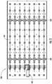
- the transmission mechanism 100 includes a plurality of connecting rods 101 arranged in parallel.
- the plurality of connecting rods 101 may be driven by a single motor 102 simultaneously to move axially, and each connecting rod 101 may drive a movable element (for example, a brush piece of a rotating brush-type phase shifter) of one or more phase shifters 103 when moving axially to adjust a directional angle (for example, an elevation angle or a downtilt angle) of antenna beams generated by the base station antenna.
- a directional angle for example, an elevation angle or a downtilt angle
- the transmission mechanism 100 includes eight connecting rods 101 arranged in parallel, and each connecting rod 101 can simultaneously drive two pairs of shifters 103 spaced apart in the axial direction of the connecting rod 101. Therefore, the transmission mechanism 100 can simultaneously drive 32 phase shifters.
- the present invention is not limited thereto, and the transmission mechanism 100 of the present invention may be used to drive any other number of phase shifters.
- the connecting rod 101 may be made of glass fiber, other plastics, or metal.
- the transmission mechanism 100 includes a worm gear unit.
- the worm gear unit includes a worm 104 extending in the direction of the connecting rod 101 and a worm gear 105 meshed and connected with the worm 104.
- the worm 104 is configured to be driven by the motor 102 to rotate about its longitudinal axis.
- one end of the worm 104 may be directly or indirectly connected with an output shaft of the motor 102, and the other end of the worm 104 may be supported by a supporting element 106.
- the worm gear 105 may be arranged above the worm 104 and rotate driven by the worm 104.
- the central axis of the worm gear 105 may be arranged to be perpendicular to the worm 104.
- the output torque of the motor 102 may be amplified to varying degrees by selecting the gear ratio of the worm gear 105 and the worm 104 of the worm gear unit, so that a single motor 102 can drive a larger number of phase shifters.
- the number of heads of the worm 104 may be 1 to 5, and the number of teeth of the worm gear 105 may be several times the number of the heads of the worm 104.
- the number of heads of the worm 104 may be 1, and the number of teeth of the worm gear 105 may be 15 to 50. Therefore, the gear ratio of the worm gear 105 and the worm 104 is from 15 to 50.
- the worm gear unit can amplify the output torque of the motor 102 by 15 to 50 times, so that when the same motor is used for driving, the pulling force generated by the transmission mechanism 100 is 15 to 50 times the pulling force generated by the transmission mechanism 1 in the prior art.
- the gear ratio of the worm gear 105 and the worm 104 may also be in other appropriate ranges, such as 5 to 50, 10 to 50, 5 to 40, 5 to 35, 5 to 30, 5 to 20, and so on.
- the worm gear unit can reduce the output rotation speed of the motor 102 while amplifying the output torque of the motor 102, and a lower rotation speed makes it possible to adjust the phase shifter more accurately.
- the worm 104 of the worm gear unit can have a smaller length, which can reduce the space occupied by the transmission mechanism 100 in the base station antenna.
- the transmission mechanism 100 further includes a plurality of gear pairs, and each gear pair is used to drive a corresponding connecting rod 101.
- each gear pair is used to further amplify the output torque of the motor 102.
- each gear pair includes a small gear 106 and a large gear 107 meshed with the small gear 106. All the small gears 106 of the plurality of gear pairs and the worm gear 105 are mounted on a common drive shaft 108 so that the small gears 106 rotate synchronously with the worm gear 105.
- the drive shaft 108 extends in a direction perpendicular to the connecting rod 101, and the small gears 106 of the plurality of gear pairs are spaced apart from each other on the drive shaft 108.
- the drive shaft 108 can ensure that the small gears 106 of the plurality of gear pairs have the same rotation speed, and can evenly transmit the output torque of the worm gear 105 to each small gear 106 via the drive shaft 108. This can solve the problem that the driving forces of the plurality of connecting rods 6 are uneven in the transmission mechanism 1 in the prior art, and thus can more accurately adjust a plurality of phase shifters in the base station antenna synchronously.
- all the large gears 107 of the plurality of gear pairs are also mounted on a common drive shaft 109 and are spaced apart from each other.
- the drive shaft 109 makes all the large gears 107 of the plurality of gear pairs have the same rotation speed and therefore have a uniform output torque.
- the output torque of the motor 102 may be further amplified to varying degrees and the output rotation speed of the motor 102 may be reduced at the same by selecting the gear ratio of the large gear 107 and the small gear 106. This makes it possible not only to use a single motor 102 to drive a larger number of phase shifters at the same time, but also to adjust the phase shifters more accurately at a lower speed.
- the drive shaft 108 may have a non-circular (for example, rectangular) cross-section, which extends through a non-circular hole provided in the center of the small gear 106 for matching with the non-circular cross section of the drive shaft 108, so that the small gear 106 is not rotatable relative to the drive shaft 108.
- the drive shaft 109 may have a non-circular (for example, rectangular) cross section, which extends through a non-circular hole provided in the center of the large gear 107 for matching with the non-circular cross section of the drive shaft 109, so that the large gear 107 is not rotatable relative to the drive shaft 109.
- the drive shaft 108 may be integrally formed with the small gear 106 and the worm gear 105, and the drive shaft 109 may be integrally formed with the large gear 107.
- a supporting member 110 may be further provided for each small gear of the plurality of gear pairs.
- Fig. 7a and Fig. 7b respectively show the specific structures of the small gear 106 and the supporting member 110 according to an embodiment of the present invention.
- the small gear 106 may include a body having a non-circular hole 111.
- the body includes a tooth portion 112 provided with teeth and a shaft portion 113 adapted to be mounted in the supporting member 110 to enable the small gear to rotate. Both ends of the shaft portion 113 are provided with flanges 114 and 115, and the flanges 114 and 115 restrict the translation of the small gear 106 relative to the supporting member 110.
- the supporting member 110 may include a base 116, a body 117 extending upright from the base 116, and an annular sleeve 118 at the top end of the body 117.
- the base 116 may be fixed in the base station antenna.
- the shaft portion 113 of the small gear 106 may be rotatably mounted in the annular sleeve 118, wherein the flanges 114 and 115 are respectively located on two sides of the annular sleeve 118 to restrict the translation of the small gear 106 relative to the supporting member 110.
- the supporting member 110 may be configured as a separate structure for ease of the installation of the small gear 106.
- each gear pair of the transmission mechanism 100 drives a corresponding connecting rod 101 through a rack element 119 meshed and connected with the large gear 107.
- the rack element 119 may be fixedly mounted on the connecting rod 101.
- the large gear 107 can axially move the connecting rod 101 via the rack element 119, thereby moving the movable element of one or more phase shifters 103.
- Each large gear 107 can drive the corresponding connecting rod 101 more stably and efficiently through the rack element 119.
- Fig. 8 shows the specific structure of the rack element 119 according to an embodiment of the present invention.
- the rack element 119 may include a bottom plate 120, a vertical plate 121 extending vertically upward from one side of the bottom plate 120, and a rack 122 located at the top end of the vertical plate 121.
- the rack 122 includes a plurality of teeth to be meshed with the large gear 107.
- the vertical plate 121 is provided with a connecting element for connecting with the connecting rod 101.
- the connecting element may include a series of posts 123 and a pair of snap clips 124.
- the post 123 is accommodated in a corresponding cylindrical hole in the corresponding connecting rod 101, and the snap clip 124 holds the connecting rod 101 in place when the post is inserted into the cylindrical hole of the connecting rod 101, thereby causing the rack element 119 to be fixed to the connecting rod 101.
- any one of a variety of connecting elements may be used, for example, a post, a bolt, a hook and a connecting fastener, a groove, etc.
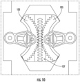
- the transmission mechanism 100 of the present invention further includes an arc-shaped connecting member 125 adapted to drive the movable element of the phase shifter to move together along an arc.
- the arc-shaped connecting member 125 is configured in the form of an arc-shaped rack, and teeth 126 are provided on the front end surface of the arc-shaped connecting member 125.
- the movable element (for example, a brush piece of a rotating brush type phase shifter) of the phase shifter may be fixedly connected with the arc-shaped connecting member 125 at the central position of the arc-shaped connecting member 125 so as to move driven by the arc-shaped connecting member 125.
- the teeth of the arc-shaped connecting member 125 are meshed with teeth 128 of a rack element 127 fixed on the connecting rod 101, so that the arc-shaped connecting member 125 rotates when the rack element 127 moves axially, thereby driving the movable element of the phase shifter to rotate.
- the rack element 127 includes a bottom plate 129.
- One surface of the bottom plate 129 is provided with a rack 129 including a plurality of teeth 128, and the opposite surface of the bottom plate 129 is provided with a connecting element such as a post and a snap clip to fix the rack element 127 on the connecting rod 101.
- each rack element 127 fixed on the connecting rod 101 can drive the movable elements of a pair of phase shifters. Therefore, the rack element 127 may include two sets of teeth 128 arranged in a mirror image, and each set of teeth 128 is meshed with the teeth 126 of an arc-shaped connecting member 125. Accordingly, the two movable elements in each pair of phase shifters are arranged so that their end portions with which the arc-shaped connecting members 125 are connected face each other.
- the pulling force of the connecting rod 101 is always maintained in the axial direction of the connecting rod 101 without component in any other directions.
- the pulling force of the connecting rod 101 can all be used to move the movable element of the phase shifter without any efficiency loss.
- the arc-shaped connecting member 125 is used, the arc-shaped groove 10 in the prior art is no longer needed. Therefore, there will not be the problem that the removable element of the phase shifter get stuck in the arc-shaped groove 10 and is difficult to move out.
- the worm gear 105, the small gear 106, the large gear 107, the rack elements 119 and 127, and the arc-shaped connecting member 125 may all be made of plastic, and the drive shafts 108 and 109 may be made of glass fiber. In order to further enhance the torsional strength of the drive shafts 108 and 109, the drive shafts 108 and 109 may also be made of metal or other materials with high torsional strength.
Landscapes
- Engineering & Computer Science (AREA)
- General Engineering & Computer Science (AREA)
- Mechanical Engineering (AREA)
- Computer Networks & Wireless Communication (AREA)
- Variable-Direction Aerials And Aerial Arrays (AREA)
- Transmission Devices (AREA)
Claims (13)
- Getriebemechanismus für eine Basisstationsantenne, beinhaltend:eine Schneckengetriebeeinheit, die eine von einem Motor (102) angetriebene Schnecke (104) und ein mit der Schnecke in Eingriff stehendes und verbundenes Schneckenrad (105) beinhaltet;wobei der Getriebemechanismus dadurch gekennzeichnet ist, dass er umfasst:eine Vielzahl von Zahnradpaaren, wobei jedes Zahnradpaar ein kleines Zahnrad (106) und ein großes Zahnrad (108) beinhaltet, die miteinander in Eingriff stehen, wobei das kleine Zahnrad und das Schneckenrad auf einer gemeinsamen ersten Antriebswelle (108) montiert sind, sodass sich das kleine Zahnrad und das Schneckenrad synchron drehen, wobei die kleinen Zahnräder voneinander beabstandet sind, wobei jedes der großen Zahnräder auf einer zweiten Antriebswelle (109) voneinander beabstandet montiert ist; undeine Vielzahl von parallel angeordneten Verbindungsstangen (101), wobei jede Verbindungsstange ein erstes Zahnstangenelement (122) beinhaltet, das fest darauf montiert ist, wobei das große Zahnrad (108) jedes Zahnradpaares mit dem ersten Zahnstangenelement (122) auf einer entsprechenden Verbindungsstange (101) in Eingriff steht und damit verbunden ist, um die Verbindungsstange (101) über das erste Zahnstangenelement (122) axial zu bewegen, wenn sich das große Zahnrad (108) jedes Zahnradpaares dreht.
- Getriebemechanismus für eine Basisstationsantenne nach Anspruch 1, wobei der Getriebemechanismus ferner ein bogenförmiges Verbindungselement (125) beinhaltet, das dazu geeignet ist, fest mit einem beweglichen Element eines Phasenschiebers verbunden zu werden, und das bogenförmige Verbindungselement dazu ausgebildet ist, drehend angetrieben zu werden, um das bewegliche Element des Phasenschiebers zu veranlassen, sich entlang eines Bogens zu bewegen.
- Getriebemechanismus für eine Basisstationsantenne nach Anspruch 2, wobei das bogenförmige Verbindungselement (125) als eine bogenförmige Zahnstange ausgebildet ist und eine Vielzahl von Zähnen (126) an einer vorderen Endfläche der bogenförmigen Zahnstange vorgesehen ist; und wobei jede Verbindungsstange (101) mindestens ein zweites Zahnstangenelement (128) beinhaltet, das daran montiert ist, und das zweite Zahnstangenelement (128) mit der Vielzahl von Zähnen (126) der bogenförmigen Zahnstange in Eingriff steht und mit diesen verbunden ist, um die bogenförmige Zahnstange zu drehen, wenn sich die Verbindungsstange (101) axial bewegt.
- Getriebemechanismus für eine Basisstationsantenne nach Anspruch 1, wobei sich die Schnecke (104) in einer Richtung der Verbindungsstangen (101) erstreckt und sich die erste Antriebswelle (108) in einer Richtung senkrecht zu den Verbindungsstangen (101) erstreckt.
- Getriebemechanismus für eine Basisstationsantenne nach Anspruch 1, wobei ein Übersetzungsverhältnis des Schneckenrads (105) und der Schnecke (104) von 15 bis 50 beträgt.
- Getriebemechanismus für eine Basisstationsantenne nach Anspruch 1, wobei die erste Antriebswelle (108) einen nicht kreisförmigen Querschnitt aufweist und das kleine Zahnrad (106) ein nicht kreisförmiges Loch (111) aufweist, das für die erste Antriebswelle (108) verwendet wird.
- Getriebemechanismus für eine Basisstationsantenne nach Anspruch 1, wobei die erste Antriebswelle (108) einstückig mit dem Schneckenrad (105) und/oder dem kleinen Zahnrad (106) ausgebildet ist.
- Getriebemechanismus für eine Basisstationsantenne nach Anspruch 1, wobei jedes Zahnradpaar ein Stützelement (110) beinhaltet, das für das kleine Zahnrad (106) verwendet wird.
- Getriebemechanismus für eine Basisstationsantenne nach Anspruch 8, wobei das kleine Zahnrad (106) einen Körper beinhaltet, der einen mit Zähnen versehenen Zahnabschnitt (112) und einen Wellenabschnitt (113) beinhaltet, der geeignet ist, in dem Stützelement (110) montiert zu werden, um dem kleinen Zahnrad (106) zu ermöglichen, sich zu drehen, und wobei das Stützelement (110) eine ringförmige Hülse (118) beinhaltet und der Wellenabschnitt des kleinen Zahnrads (106) drehbar in der ringförmigen Hülse (118) montiert ist.
- Getriebemechanismus für eine Basisstationsantenne nach Anspruch 1, wobei das erste Zahnstangenelement (122) eine Bodenplatte (120), eine vertikale Platte (121), die sich von einer Seite der Bodenplatte (120) vertikal nach oben erstreckt, und eine Zahnstange (122) beinhaltet, die an einem oberen Ende der vertikalen Platte angeordnet ist, und die vertikale Platte (212) mit einem Verbindungselement (123, 124) für eine Verbindung mit den Verbindungsstangen (101) vorgesehen ist.
- Getriebemechanismus für eine Basisstationsantenne nach Anspruch 10, wobei das Verbindungselement (123, 124) eines oder mehrere beinhaltet, ausgewählt aus der Gruppe bestehend aus einem Pfosten, einem Schnappverschluss, einem Bolzen, einem Haken und einem Verbindungselement und einer Nut.
- Getriebemechanismus für eine Basisstationsantenne nach Anspruch 1, wobei der Getriebemechanismus dazu ausgebildet ist, mindestens 32 Phasenschieber gleichzeitig durch einen einzigen Motor anzutreiben.
- Basisstationsantenne, beinhaltend den Getriebemechanismus für eine Basisstationsantenne nach einem der Ansprüche 1 bis 12.
Applications Claiming Priority (2)
| Application Number | Priority Date | Filing Date | Title |
|---|---|---|---|
| CN202010840645.1A CN114079144A (zh) | 2020-08-20 | 2020-08-20 | 用于基站天线的传动机构和基站天线 |
| PCT/US2021/044131 WO2022039915A1 (en) | 2020-08-20 | 2021-08-02 | Transmission mechanism for base station antenna and base station antenna |
Publications (3)
| Publication Number | Publication Date |
|---|---|
| EP4000127A1 EP4000127A1 (de) | 2022-05-25 |
| EP4000127A4 EP4000127A4 (de) | 2023-07-12 |
| EP4000127B1 true EP4000127B1 (de) | 2025-06-04 |
Family
ID=80282926
Family Applications (1)
| Application Number | Title | Priority Date | Filing Date |
|---|---|---|---|
| EP21854863.4A Active EP4000127B1 (de) | 2020-08-20 | 2021-08-02 | Übertragungsmechanismus für basisstationsantenne und basisstationsantenne |
Country Status (5)
| Country | Link |
|---|---|
| US (1) | US11984662B2 (de) |
| EP (1) | EP4000127B1 (de) |
| CN (1) | CN114079144A (de) |
| FI (1) | FI4000127T3 (de) |
| WO (1) | WO2022039915A1 (de) |
Families Citing this family (2)
| Publication number | Priority date | Publication date | Assignee | Title |
|---|---|---|---|---|
| WO2022141325A1 (zh) * | 2020-12-30 | 2022-07-07 | 华为技术有限公司 | 一种天线齿轮箱传动机构以及天线 |
| CN116845529B (zh) * | 2023-07-06 | 2024-05-14 | 广东博纬通信科技有限公司 | 一种基站天线传动装置 |
Family Cites Families (15)
| Publication number | Priority date | Publication date | Assignee | Title |
|---|---|---|---|---|
| KR101314269B1 (ko) * | 2011-10-05 | 2013-10-02 | (주)하이게인안테나 | 안테나 위상 변위기 |
| CN111129715B (zh) * | 2015-12-31 | 2021-12-10 | 华为技术有限公司 | 包含波束成形装置的天线 |
| CN105720370B (zh) | 2016-01-25 | 2019-01-25 | 华为技术有限公司 | 一种天线方位角调节装置 |
| CN206274548U (zh) | 2016-11-01 | 2017-06-23 | 昆山恩电开通信设备有限公司 | 低剖面多阵列天线移相传动装置 |
| CN109755747B (zh) | 2017-11-07 | 2025-02-07 | 普罗斯通信技术(苏州)有限公司 | 一种天线移相器传动装置 |
| DE102018119418A1 (de) * | 2018-08-09 | 2020-02-13 | Maul Konstruktionen GmbH | Zahnstangengetriebe |
| CN120767589A (zh) * | 2018-08-10 | 2025-10-10 | 户外无线网络有限公司 | 移相器组件 |
| CN111412261A (zh) * | 2019-01-04 | 2020-07-14 | 康普技术有限责任公司 | 用于基站天线的操纵器组件 |
| CN110492246B (zh) * | 2019-08-13 | 2021-05-28 | 中信科移动通信技术有限公司 | 基站天线电下倾角调节传动机构及基站天线 |
| CN110931980B (zh) * | 2019-12-12 | 2021-06-11 | 罗森伯格技术有限公司 | 一种移相器传动装置 |
| CN111180893A (zh) * | 2020-01-06 | 2020-05-19 | 武汉虹信通信技术有限责任公司 | 传动装置及电调天线 |
| CN213602013U (zh) * | 2020-12-29 | 2021-07-02 | 罗森伯格技术有限公司 | 用于天线的传动装置 |
| CN115207603A (zh) * | 2021-04-14 | 2022-10-18 | 康普技术有限责任公司 | 用于基站天线的传动机构和基站天线 |
| CN114465005B (zh) * | 2022-03-24 | 2025-12-23 | 广东博纬通信科技有限公司 | 一种电下倾角调整装置及基站天线 |
| CN116053786A (zh) * | 2022-08-23 | 2023-05-02 | 普罗斯通信技术(苏州)有限公司 | 一种移相器 |
-
2020
- 2020-08-20 CN CN202010840645.1A patent/CN114079144A/zh active Pending
-
2021
- 2021-08-02 FI FIEP21854863.4T patent/FI4000127T3/fi active
- 2021-08-02 WO PCT/US2021/044131 patent/WO2022039915A1/en not_active Ceased
- 2021-08-02 EP EP21854863.4A patent/EP4000127B1/de active Active
- 2021-08-02 US US17/632,096 patent/US11984662B2/en active Active
Also Published As
| Publication number | Publication date |
|---|---|
| CN114079144A (zh) | 2022-02-22 |
| EP4000127A1 (de) | 2022-05-25 |
| US11984662B2 (en) | 2024-05-14 |
| FI4000127T3 (fi) | 2025-09-02 |
| US20230307830A1 (en) | 2023-09-28 |
| EP4000127A4 (de) | 2023-07-12 |
| WO2022039915A1 (en) | 2022-02-24 |
Similar Documents
| Publication | Publication Date | Title |
|---|---|---|
| US11909095B2 (en) | Transmission mechanism for base station antenna and base station antenna | |
| US20210408679A1 (en) | Switchable transmission mechanism for a base station antenna | |
| US11600920B2 (en) | Remote electronic tilt actuators for controlling multiple phase shifters and base station antennas with remote electronic tilt actuators | |
| US11289799B2 (en) | Base station antennas with compact remote electronic tilt actuators for controlling multiple phase shifters | |
| US11984662B2 (en) | Transmission mechanism for base station antenna and base station antenna | |
| CN110476299B (zh) | 可配置用于进行独立或共同下倾控制的基站天线和相关方法 | |
| US20200373663A1 (en) | Base station antennas with remote electronic tilt actuators for controlling multiple phase shifters | |
| US20230053624A1 (en) | Remote electronic tilt base station antennas having adjustable ret linkages | |
| JP4815574B2 (ja) | 移動通信基地局のアンテナビーム制御装置 | |
| CN100426588C (zh) | 用于蜂窝通信的天线波束控制系统 | |
| EP4503333A1 (de) | Elektrische downtilt-winkelanpassungsvorrichtung und basisstationsantenne | |
| CN112751163A (zh) | 具有可调ret杆支撑件的远程电子倾斜基站天线 | |
| CN111180893A (zh) | 传动装置及电调天线 | |
| US12183965B2 (en) | Transmission mechanism for base station antenna and base station antenna | |
| WO2021120736A1 (zh) | 天线传动装置及天线 | |
| US20230139300A1 (en) | Remote electronic tilt actuators for controlling multiple phase shifters and base station antennas with remote electronic tilt actuators | |
| US20200358170A1 (en) | Base station antennas with mechanical linkages having flexible drive shafts | |
| US12537297B2 (en) | Transmission mechanism for base station antenna | |
| US12519224B2 (en) | Transmission device for base station antenna and base station antenna | |
| CN117673748A (zh) | 一种超大大规模mimo多波束透镜天线系统 | |
| KR102728668B1 (ko) | 틸트구조를 갖는 직구동 타입의 위성안테나. | |
| US12368233B2 (en) | Base station antenna with mutual downtilt in multiple frequency bands | |
| US20260045686A1 (en) | Three-sector base station antenna | |
| JP2000031733A (ja) | 偏波切換アンテナ装置 | |
| CN117410670A (zh) | 一种全向天线 |
Legal Events
| Date | Code | Title | Description |
|---|---|---|---|
| STAA | Information on the status of an ep patent application or granted ep patent |
Free format text: STATUS: UNKNOWN |
|
| STAA | Information on the status of an ep patent application or granted ep patent |
Free format text: STATUS: THE INTERNATIONAL PUBLICATION HAS BEEN MADE |
|
| PUAI | Public reference made under article 153(3) epc to a published international application that has entered the european phase |
Free format text: ORIGINAL CODE: 0009012 |
|
| STAA | Information on the status of an ep patent application or granted ep patent |
Free format text: STATUS: REQUEST FOR EXAMINATION WAS MADE |
|
| 17P | Request for examination filed |
Effective date: 20220217 |
|
| AK | Designated contracting states |
Kind code of ref document: A1 Designated state(s): AL AT BE BG CH CY CZ DE DK EE ES FI FR GB GR HR HU IE IS IT LI LT LU LV MC MK MT NL NO PL PT RO RS SE SI SK SM TR |
|
| A4 | Supplementary search report drawn up and despatched |
Effective date: 20230609 |
|
| RIC1 | Information provided on ipc code assigned before grant |
Ipc: F16H 19/04 20060101ALI20230602BHEP Ipc: H01Q 1/24 20060101ALI20230602BHEP Ipc: H01Q 1/12 20060101AFI20230602BHEP |
|
| DAV | Request for validation of the european patent (deleted) | ||
| DAX | Request for extension of the european patent (deleted) | ||
| STAA | Information on the status of an ep patent application or granted ep patent |
Free format text: STATUS: EXAMINATION IS IN PROGRESS |
|
| 17Q | First examination report despatched |
Effective date: 20240314 |
|
| RAP3 | Party data changed (applicant data changed or rights of an application transferred) |
Owner name: COMMSCOPE TECHNOLOGIES LLC |
|
| RAP1 | Party data changed (applicant data changed or rights of an application transferred) |
Owner name: OUTDOOR WIRELESS NETWORKS LLC |
|
| GRAP | Despatch of communication of intention to grant a patent |
Free format text: ORIGINAL CODE: EPIDOSNIGR1 |
|
| STAA | Information on the status of an ep patent application or granted ep patent |
Free format text: STATUS: GRANT OF PATENT IS INTENDED |
|
| INTG | Intention to grant announced |
Effective date: 20241204 |
|
| GRAS | Grant fee paid |
Free format text: ORIGINAL CODE: EPIDOSNIGR3 |
|
| GRAA | (expected) grant |
Free format text: ORIGINAL CODE: 0009210 |
|
| STAA | Information on the status of an ep patent application or granted ep patent |
Free format text: STATUS: THE PATENT HAS BEEN GRANTED |
|
| AK | Designated contracting states |
Kind code of ref document: B1 Designated state(s): AL AT BE BG CH CY CZ DE DK EE ES FI FR GB GR HR HU IE IS IT LI LT LU LV MC MK MT NL NO PL PT RO RS SE SI SK SM TR |
|
| REG | Reference to a national code |
Ref country code: GB Ref legal event code: FG4D |
|
| REG | Reference to a national code |
Ref country code: CH Ref legal event code: EP |
|
| REG | Reference to a national code |
Ref country code: DE Ref legal event code: R096 Ref document number: 602021031928 Country of ref document: DE |
|
| REG | Reference to a national code |
Ref country code: IE Ref legal event code: FG4D |
|
| REG | Reference to a national code |
Ref country code: FI Ref legal event code: FGE |
|
| REG | Reference to a national code |
Ref country code: SE Ref legal event code: TRGR |
|
| REG | Reference to a national code |
Ref country code: NL Ref legal event code: MP Effective date: 20250604 |
|
| PG25 | Lapsed in a contracting state [announced via postgrant information from national office to epo] |
Ref country code: ES Free format text: LAPSE BECAUSE OF FAILURE TO SUBMIT A TRANSLATION OF THE DESCRIPTION OR TO PAY THE FEE WITHIN THE PRESCRIBED TIME-LIMIT Effective date: 20250604 |
|
| PGFP | Annual fee paid to national office [announced via postgrant information from national office to epo] |
Ref country code: FI Payment date: 20250828 Year of fee payment: 5 |
|
| REG | Reference to a national code |
Ref country code: LT Ref legal event code: MG9D |
|
| PG25 | Lapsed in a contracting state [announced via postgrant information from national office to epo] |
Ref country code: NO Free format text: LAPSE BECAUSE OF FAILURE TO SUBMIT A TRANSLATION OF THE DESCRIPTION OR TO PAY THE FEE WITHIN THE PRESCRIBED TIME-LIMIT Effective date: 20250904 Ref country code: GR Free format text: LAPSE BECAUSE OF FAILURE TO SUBMIT A TRANSLATION OF THE DESCRIPTION OR TO PAY THE FEE WITHIN THE PRESCRIBED TIME-LIMIT Effective date: 20250905 |
|
| PG25 | Lapsed in a contracting state [announced via postgrant information from national office to epo] |
Ref country code: PL Free format text: LAPSE BECAUSE OF FAILURE TO SUBMIT A TRANSLATION OF THE DESCRIPTION OR TO PAY THE FEE WITHIN THE PRESCRIBED TIME-LIMIT Effective date: 20250604 |
|
| PG25 | Lapsed in a contracting state [announced via postgrant information from national office to epo] |
Ref country code: BG Free format text: LAPSE BECAUSE OF FAILURE TO SUBMIT A TRANSLATION OF THE DESCRIPTION OR TO PAY THE FEE WITHIN THE PRESCRIBED TIME-LIMIT Effective date: 20250604 |
|
| PG25 | Lapsed in a contracting state [announced via postgrant information from national office to epo] |
Ref country code: HR Free format text: LAPSE BECAUSE OF FAILURE TO SUBMIT A TRANSLATION OF THE DESCRIPTION OR TO PAY THE FEE WITHIN THE PRESCRIBED TIME-LIMIT Effective date: 20250604 |
|
| PGFP | Annual fee paid to national office [announced via postgrant information from national office to epo] |
Ref country code: AT Payment date: 20251020 Year of fee payment: 5 |
|
| PGFP | Annual fee paid to national office [announced via postgrant information from national office to epo] |
Ref country code: SE Payment date: 20250829 Year of fee payment: 5 |
|
| PG25 | Lapsed in a contracting state [announced via postgrant information from national office to epo] |
Ref country code: RS Free format text: LAPSE BECAUSE OF FAILURE TO SUBMIT A TRANSLATION OF THE DESCRIPTION OR TO PAY THE FEE WITHIN THE PRESCRIBED TIME-LIMIT Effective date: 20250904 |
|
| PG25 | Lapsed in a contracting state [announced via postgrant information from national office to epo] |
Ref country code: LV Free format text: LAPSE BECAUSE OF FAILURE TO SUBMIT A TRANSLATION OF THE DESCRIPTION OR TO PAY THE FEE WITHIN THE PRESCRIBED TIME-LIMIT Effective date: 20250604 |
|
| PG25 | Lapsed in a contracting state [announced via postgrant information from national office to epo] |
Ref country code: NL Free format text: LAPSE BECAUSE OF FAILURE TO SUBMIT A TRANSLATION OF THE DESCRIPTION OR TO PAY THE FEE WITHIN THE PRESCRIBED TIME-LIMIT Effective date: 20250604 |
|
| PG25 | Lapsed in a contracting state [announced via postgrant information from national office to epo] |
Ref country code: PT Free format text: LAPSE BECAUSE OF FAILURE TO SUBMIT A TRANSLATION OF THE DESCRIPTION OR TO PAY THE FEE WITHIN THE PRESCRIBED TIME-LIMIT Effective date: 20251006 |
|
| REG | Reference to a national code |
Ref country code: AT Ref legal event code: MK05 Ref document number: 1801301 Country of ref document: AT Kind code of ref document: T Effective date: 20250604 |
|
| PG25 | Lapsed in a contracting state [announced via postgrant information from national office to epo] |
Ref country code: IS Free format text: LAPSE BECAUSE OF FAILURE TO SUBMIT A TRANSLATION OF THE DESCRIPTION OR TO PAY THE FEE WITHIN THE PRESCRIBED TIME-LIMIT Effective date: 20251004 |
|
| PG25 | Lapsed in a contracting state [announced via postgrant information from national office to epo] |
Ref country code: SM Free format text: LAPSE BECAUSE OF FAILURE TO SUBMIT A TRANSLATION OF THE DESCRIPTION OR TO PAY THE FEE WITHIN THE PRESCRIBED TIME-LIMIT Effective date: 20250604 Ref country code: AT Free format text: LAPSE BECAUSE OF FAILURE TO SUBMIT A TRANSLATION OF THE DESCRIPTION OR TO PAY THE FEE WITHIN THE PRESCRIBED TIME-LIMIT Effective date: 20250604 |
|
| PG25 | Lapsed in a contracting state [announced via postgrant information from national office to epo] |
Ref country code: CZ Free format text: LAPSE BECAUSE OF FAILURE TO SUBMIT A TRANSLATION OF THE DESCRIPTION OR TO PAY THE FEE WITHIN THE PRESCRIBED TIME-LIMIT Effective date: 20250604 |
|
| PG25 | Lapsed in a contracting state [announced via postgrant information from national office to epo] |
Ref country code: EE Free format text: LAPSE BECAUSE OF FAILURE TO SUBMIT A TRANSLATION OF THE DESCRIPTION OR TO PAY THE FEE WITHIN THE PRESCRIBED TIME-LIMIT Effective date: 20250604 |
|
| PG25 | Lapsed in a contracting state [announced via postgrant information from national office to epo] |
Ref country code: SK Free format text: LAPSE BECAUSE OF FAILURE TO SUBMIT A TRANSLATION OF THE DESCRIPTION OR TO PAY THE FEE WITHIN THE PRESCRIBED TIME-LIMIT Effective date: 20250604 Ref country code: RO Free format text: LAPSE BECAUSE OF FAILURE TO SUBMIT A TRANSLATION OF THE DESCRIPTION OR TO PAY THE FEE WITHIN THE PRESCRIBED TIME-LIMIT Effective date: 20250604 |
|
| PG25 | Lapsed in a contracting state [announced via postgrant information from national office to epo] |
Ref country code: IT Free format text: LAPSE BECAUSE OF FAILURE TO SUBMIT A TRANSLATION OF THE DESCRIPTION OR TO PAY THE FEE WITHIN THE PRESCRIBED TIME-LIMIT Effective date: 20250604 |
|
| REG | Reference to a national code |
Ref country code: DE Ref legal event code: R119 Ref document number: 602021031928 Country of ref document: DE |
|
| REG | Reference to a national code |
Ref country code: CH Ref legal event code: H13 Free format text: ST27 STATUS EVENT CODE: U-0-0-H10-H13 (AS PROVIDED BY THE NATIONAL OFFICE) Effective date: 20260324 |
|
| PG25 | Lapsed in a contracting state [announced via postgrant information from national office to epo] |
Ref country code: MC Free format text: LAPSE BECAUSE OF FAILURE TO SUBMIT A TRANSLATION OF THE DESCRIPTION OR TO PAY THE FEE WITHIN THE PRESCRIBED TIME-LIMIT Effective date: 20250604 |
|
| PLBE | No opposition filed within time limit |
Free format text: ORIGINAL CODE: 0009261 |
|
| STAA | Information on the status of an ep patent application or granted ep patent |
Free format text: STATUS: NO OPPOSITION FILED WITHIN TIME LIMIT |
|
| PG25 | Lapsed in a contracting state [announced via postgrant information from national office to epo] |
Ref country code: DK Free format text: LAPSE BECAUSE OF FAILURE TO SUBMIT A TRANSLATION OF THE DESCRIPTION OR TO PAY THE FEE WITHIN THE PRESCRIBED TIME-LIMIT Effective date: 20250604 |
|
| PG25 | Lapsed in a contracting state [announced via postgrant information from national office to epo] |
Ref country code: LU Free format text: LAPSE BECAUSE OF NON-PAYMENT OF DUE FEES Effective date: 20250802 |
|
| REG | Reference to a national code |
Ref country code: CH Ref legal event code: L10 Free format text: ST27 STATUS EVENT CODE: U-0-0-L10-L00 (AS PROVIDED BY THE NATIONAL OFFICE) Effective date: 20260416 |
|
| PG25 | Lapsed in a contracting state [announced via postgrant information from national office to epo] |
Ref country code: CH Free format text: LAPSE BECAUSE OF NON-PAYMENT OF DUE FEES Effective date: 20250831 |
|
| 26N | No opposition filed |
Effective date: 20260305 |