EP4503333A1 - Elektrische downtilt-winkelanpassungsvorrichtung und basisstationsantenne - Google Patents
Elektrische downtilt-winkelanpassungsvorrichtung und basisstationsantenne Download PDFInfo
- Publication number
- EP4503333A1 EP4503333A1 EP23773585.7A EP23773585A EP4503333A1 EP 4503333 A1 EP4503333 A1 EP 4503333A1 EP 23773585 A EP23773585 A EP 23773585A EP 4503333 A1 EP4503333 A1 EP 4503333A1
- Authority
- EP
- European Patent Office
- Prior art keywords
- transmission
- bevel gear
- position selection
- gear
- angle adjustment
- Prior art date
- Legal status (The legal status is an assumption and is not a legal conclusion. Google has not performed a legal analysis and makes no representation as to the accuracy of the status listed.)
- Pending
Links
Images


Classifications
-
- H—ELECTRICITY
- H01—ELECTRIC ELEMENTS
- H01Q—ANTENNAS, i.e. RADIO AERIALS
- H01Q1/00—Details of, or arrangements associated with, antennas
- H01Q1/12—Supports; Mounting means
- H01Q1/125—Means for positioning
- H01Q1/1264—Adjusting different parts or elements of an aerial unit
-
- H—ELECTRICITY
- H01—ELECTRIC ELEMENTS
- H01P—WAVEGUIDES; RESONATORS, LINES, OR OTHER DEVICES OF THE WAVEGUIDE TYPE
- H01P1/00—Auxiliary devices
- H01P1/18—Phase-shifters
-
- H—ELECTRICITY
- H01—ELECTRIC ELEMENTS
- H01Q—ANTENNAS, i.e. RADIO AERIALS
- H01Q1/00—Details of, or arrangements associated with, antennas
- H01Q1/12—Supports; Mounting means
-
- H—ELECTRICITY
- H01—ELECTRIC ELEMENTS
- H01Q—ANTENNAS, i.e. RADIO AERIALS
- H01Q1/00—Details of, or arrangements associated with, antennas
- H01Q1/12—Supports; Mounting means
- H01Q1/20—Resilient mountings
-
- H—ELECTRICITY
- H01—ELECTRIC ELEMENTS
- H01Q—ANTENNAS, i.e. RADIO AERIALS
- H01Q1/00—Details of, or arrangements associated with, antennas
- H01Q1/12—Supports; Mounting means
- H01Q1/22—Supports; Mounting means by structural association with other equipment or articles
- H01Q1/24—Supports; Mounting means by structural association with other equipment or articles with receiving set
- H01Q1/241—Supports; Mounting means by structural association with other equipment or articles with receiving set used in mobile communications, e.g. GSM
- H01Q1/246—Supports; Mounting means by structural association with other equipment or articles with receiving set used in mobile communications, e.g. GSM specially adapted for base stations
-
- H—ELECTRICITY
- H01—ELECTRIC ELEMENTS
- H01Q—ANTENNAS, i.e. RADIO AERIALS
- H01Q3/00—Arrangements for changing or varying the orientation or the shape of the directional pattern of the waves radiated from an antenna or antenna system
- H01Q3/26—Arrangements for changing or varying the orientation or the shape of the directional pattern of the waves radiated from an antenna or antenna system varying the relative phase or relative amplitude of energisation between two or more active radiating elements; varying the distribution of energy across a radiating aperture
- H01Q3/30—Arrangements for changing or varying the orientation or the shape of the directional pattern of the waves radiated from an antenna or antenna system varying the relative phase or relative amplitude of energisation between two or more active radiating elements; varying the distribution of energy across a radiating aperture varying the relative phase between the radiating elements of an array
- H01Q3/34—Arrangements for changing or varying the orientation or the shape of the directional pattern of the waves radiated from an antenna or antenna system varying the relative phase or relative amplitude of energisation between two or more active radiating elements; varying the distribution of energy across a radiating aperture varying the relative phase between the radiating elements of an array by electrical means
-
- H—ELECTRICITY
- H01—ELECTRIC ELEMENTS
- H01Q—ANTENNAS, i.e. RADIO AERIALS
- H01Q3/00—Arrangements for changing or varying the orientation or the shape of the directional pattern of the waves radiated from an antenna or antenna system
- H01Q3/26—Arrangements for changing or varying the orientation or the shape of the directional pattern of the waves radiated from an antenna or antenna system varying the relative phase or relative amplitude of energisation between two or more active radiating elements; varying the distribution of energy across a radiating aperture
- H01Q3/30—Arrangements for changing or varying the orientation or the shape of the directional pattern of the waves radiated from an antenna or antenna system varying the relative phase or relative amplitude of energisation between two or more active radiating elements; varying the distribution of energy across a radiating aperture varying the relative phase between the radiating elements of an array
- H01Q3/32—Arrangements for changing or varying the orientation or the shape of the directional pattern of the waves radiated from an antenna or antenna system varying the relative phase or relative amplitude of energisation between two or more active radiating elements; varying the distribution of energy across a radiating aperture varying the relative phase between the radiating elements of an array by mechanical means
Definitions
- the present invention relates to the technical field of antennas, in particular to an electric downtilt angle adjustment apparatus and a base station antenna.
- the antenna downtilt is mainly adjusted by mechanical downtilt and electric downtilt.
- the electric downtilt can be controlled by remote electric adjustment, which has low cost, so it has been widely used.
- the object of the present invention is to provide an antenna electrical downtilt angle adjustment apparatus which has a simple structure, is easy to manufacture, has a low cost, a light weight, a small size and a reliable quality, that is, a base station antenna using the antenna electrical downtilt angle adjustment apparatus.
- the moving switching mechanism comprises a transmission shaft and a position selection rack, wherein both ends of the position selection rack are respectively provided with position selection fixing holes, and the position selection fixing holes at both ends are respectively provided with transmission gears; the transmission shaft passes through the position selection fixing holes and the holes of the transmission gears, and both ends are respectively connected with the support frame; and the position selection rack is provided with a position selection input gear, and the rotation of the position selection input gear is capable of driving the position selection rack and the transmission gear to slide along an axial direction of the transmission shaft.
- a further improvement is that a circular shaft elastic arm is arranged on the transmission gear, and the circular shaft elastic arm is capable of rotating in the position selection fixing hole of the position selection rack; and an end part of the transmission gear is provided with an reverse buckle buckled on the position selection fixing hole.
- the driving member comprises a transmission input bevel gear and a first bevel gear; the first bevel gear is sleeved on the transmission shaft, the rotation of the first bevel gear is capable of driving the transmission shaft and the transmission gear to rotate synchronously, and the rotation of the transmission input bevel gear is capable of driving the first bevel gear to rotate.
- a further improvement is that the second guide shaft is provided with a plurality of clamp grooves, and a backstop surface of the transmission intermediate wheel is provided with a clamp ring; after passing through the holes of the transmission intermediate wheels one by one, the second guide shaft is buckled in the corresponding clamp groove on the second guide shaft by the clamp ring.
- phase shift assembly comprises a fixed seat located at one side of the position selection transmission assembly;
- driven member comprises an internal thread strip and an external thread column, wherein the internal thread strip is installed in a guide groove of the fixed seat, and the external thread column is placed below the internal thread strip;
- the rotation of the transmission intermediate wheel is capable of driving the external thread column to rotate, and the rotation of the external thread column is capable of driving the internal thread strip to slide in the guide groove.
- the driven member further comprises a third bevel gear, a second bevel gear is arranged on the transmission intermediate wheel, and the second bevel gear is meshed with the corresponding third bevel gear;
- the third bevel gear sequentially passes through a first circular hole of the fixed seat, a through hole of the external thread column and a second circular hole of the fixed seat;
- the third bevel gear is in transmission connection with the external thread column, and the third bevel gear is capable of rotating in the first circular hole and the second circular hole of the fixed seat.
- a further improvement is that a damping ring is arranged between the third bevel gear and the first circular hole of the fixed seat.
- a further improvement is that a rear part of the third bevel gear is provided with a elastic buckle, and the elastic buckle is buckled on an end face of the second circular hole of the fixed seat to prevent the third bevel gear from coming loose from the fixed seat.
- a second aspect of the present invention provides a base station antenna, including the electric downtilt angle adjustment apparatus according to the first aspect.
- the present invention has the following beneficial effects:
- the rotation of the transmission input bevel gear is capable of driving the rotation of the first bevel gear, thereby driving the synchronous rotation of the transmission shaft and the transmission gear.
- the rotation of the transmission gear is capable of driving the rotation of a certain transmission intermediate wheel meshed with it.
- the transmission intermediate wheel Because the second bevel gear of the transmission intermediate wheel is meshed with the third bevel gear, and under the action of the clamp ring, the transmission intermediate wheel has been fixed along the axial direction of the second guide shaft and can only rotate along the axial center of the second guide shaft, while the rotation of the transmission intermediate wheel is capable of driving the rotation of the third bevel gear, thus driving the internal thread strip to move back and forth in the guide groove, and the end of the internal thread strip can be connected with the corresponding phase shifter, thus realizing the adjustment of the tilt angle of the phase shifter.
- the electric downtilt angle adjustment apparatus provided by the present invention has the advantages of simple structure, convenient manufacture, low cost, light weight, small size and reliable quality.
- an lock hook is arranged on the support frame, the two ends of the transmission shaft are provided with circular grooves, and the lock hook of the support frame is clamped in the circular grooves of the transmission shaft, so that the support frame can be prevented from falling off; the position selection transmission assembly is integrated, which is convenient for the turnover and installation of the position selection transmission assembly as a module on the production line.
- a damping ring is added between the third bevel gear and the first circular hole of the fixed seat, so that the internal thread strip can be prevented from sliding back and forth when the third bevel gear is in a non-working state, such as jitter in the product transportation process; and by arranging the elastic buckle, the elastic buckle is buckled on the end face of the second circular hole of the fixed seat, so that the third bevel gear can be prevented from loosening from the fixed seat, so that the phase shift assembly is integrated, and the turnover and installation of the phase shift assembly as a module on the production line are facilitated.
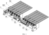
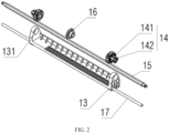
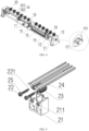
- Position selection transmission assembly 2. Phase shift assemblies; 10. Position selection input gear; 11. Transmission input bevel gear; 12. Support frame; 13. Position selection rack; 14. Transmission gear; 141, Circular shaft elastic arm; 142. Reverse buckle; 15. Transmission shaft; 16. First bevel gear; 17. First guide shaft; 18. Transmission intermediate wheel; 181, Second bevel gear; 182, Backstop surface; 19. Second guide shaft; 191, clamp groove; 20, clamp ring; 21. Fixed seat; 211. The first circular hole; 212, the second circular hole; 22. The third bevel gear; 221, snap; 23. External thread column; 24, internal thread; 25. Damping ring.
- first and second in the present invention do not represent the specific number and order, but are only used to distinguish names.
- FIGs 1- 7 An embodiment of the present invention will be described in detail with reference to FIGs 1- 7 :
- An embodiment of the first aspect of the present invention provides an electric downtilt angle adjustment apparatus.
- the application solution of the present invention consists of the following components:
- the moving switching mechanism includes a transmission shaft 15 and a position selection rack 13, wherein both ends of the position selection rack 13 are respectively provided with positioning fixing holes 131, and the positioning fixing holes 131 at both ends are respectively provided with transmission gears 14; the transmission shaft 15 passes through the positioning fixing holes 131 and the holes of the transmission gear 14, and both ends are respectively connected with the support frame 12; and the position selection rack 13 is provided with a positioning input gear 10, and the rotation of the positioning input gear 10 is capable of driving the position selection rack 13 and the transmission gear 14 to slide along the axial direction of the transmission shaft 15.
- the driving member includes a transmission input bevel gear 11 and a first bevel gear 16, and the first bevel gear 16 is sleeved on the transmission shaft 15.
- the rotation of the first bevel gear 16 is capable of driving the transmission shaft 15 and the transmission gear 14 to rotate synchronously, and the rotation of the transmission input bevel gear 11 is capable of driving the first bevel gear 16 to rotate.
- the transmission gear 14 is symmetrically installed on the position selection fixing holes 131 at both ends of the position selection rack 13.
- the transmission gear 14 is provided with a circular shaft elastic arm 141, which is capable of rotating in the position selection fixing hole 131 of the position selection rack 13, and the end of the transmission gear 14 is provided with a reverse buckle 142, which can be buckled on the position selection fixing hole 131.
- the transmission shaft 15 passes through the holes of the transmission gear 14, the first bevel gear 16 and another transmission gear 14 respectively, and the transmission shaft 15 can be matched with the transmission gear 14 and the first bevel gear 16 by a spline structure, therefore the rotation of the first bevel gear 16 is capable of driving the transmission shaft 15 and the transmission gear 14 to rotate synchronously.
- the support frame 12 is also provided with a first guide shaft 17, which passes through both ends of the position selection rack 13, and the position selection rack 13 is capable of driving the transmission gear 14 buckled on the fixing hole 131 to slide freely along the axial direction of the transmission shaft 15 (or the first guide shaft 17) as a whole, so that the sliding of the position selection rack 13 is more stable under the joint action of the first guide shaft 17 and the transmission shaft 15.
- the second guide shaft 19 is provided with a plurality of clamp grooves 191, and the backstop surface 182 of the transmission intermediate wheel 18 is provided with a clamp ring 20.
- the second guide shaft 19 passes through the holes of the transmission intermediate wheels 18 one by one, the second guide shaft 19 is correspondingly buckled in the corresponding clamp groove 191 with the clamp ring 20, so that the transmission intermediate wheels 18 are evenly and symmetrically distributed on both sides of the second guide shaft 19.
- the transmission intermediate wheel 18 can freely rotate along the axis of the first guide shaft 17, and the clamp ring 20 is placed on the backstop surface 182 of the transmission intermediate wheel 18 to prevent the transmission intermediate wheel 18 from sliding to the other side along the axis direction of the second guide shaft 19.
- the installation position and number of the clamp ring 20 and the transmission intermediate wheel 18 can be adjusted according to the requirements of antenna implementation, and the embodiment of the present invention adopts 12 paths for explanation.
- the support frame 12 is installed at both ends of the first guide shaft 17, the second guide shaft 19 and the transmission shaft 15, and plays a role in supporting and positioning the first guide shaft 17, the second guide shaft 19 and the transmission shaft 15.
- the transmission shaft 15 can freely rotate in the fixing holes at both ends of the support frame 12, and the support frame 12 is provided with lock hooks 121, and both ends of the transmission shaft 15 are provided with circular grooves 151, and the lock hooks 121 of the support frame 12 are clamped in the circular grooves 151 of the transmission shaft 15, so that the support frame 12 can be prevented from falling off, and the position selection transmission assembly 1 is integrated, which is convenient for the rotation and installation of the position selection transmission assembly 1 as a module on the production line.
- the rotation of the position selection input gear 10 is capable of driving the position selection rack 13 to slide along the axial direction of the transmission shaft 15 (or the first guide shaft 17), and the sliding of the position selection rack 13 is capable of driving the transmission gear 14 buckled on the position selection fixing hole 131 to move correspondingly.
- the transmission gear 14 can be sequentially meshed with the transmission intermediate wheels 18 fixed on the second guide shaft 19, thus completing the position selection of the transmission intermediate wheels 18 at different positions.
- the number of transmission gears 14 can be designed as one or several (the number of transmission gears 14 in this example is two) according to the efficiency requirement of gear shifting. When one of the transmission gears 14 is meshed with any transmission intermediate wheel 18, the transmission gears 14 in other positions need to be completely separated from the transmission intermediate wheel 18.
- the phase shift assembly 2 includes a fixed seat 21 located at one side of the position selection transmission assembly 1, and the driven member includes an internal thread strip 24 and an external thread column 23.
- the internal thread strip 24 is installed in a guide groove of the fixed seat 21, and the internal thread strip 24 can freely slide in the guide groove, and the external thread column 23 is placed below the internal thread strip 24.
- other transmission modes such as worm gear and screw can be adopted between the external thread column 23 and the internal thread strip 24.
- the rotation of the transmission intermediate wheel 18 is capable of driving the external thread column 23 to rotate, and the rotation of the external thread column 23 is capable of driving the internal thread strip 24 to slide in the guide groove.
- the driven member also includes a third bevel gear 22, and a second bevel gear 181 is arranged on the transmission intermediate wheel 18; the second bevel gear 181 is meshed with the corresponding third bevel gear 22, and a damping ring 25 is arranged between the third bevel gear 22 and the first circular hole 211 of the fixed seat 21.
- the third bevel gear 22 passes through the damping ring 25, the first circular hole 211 of the fixed seat 21, the through hole of the external thread column 23 and the second circular hole 212 of the fixed seat 21 in turn, and the third bevel gear 22 is in a drivable connection with the external thread column 23.
- the drivable connection between the third bevel gear 22 and the external thread column 23 can be realized by cooperation of a spline structural.
- the third bevel gear 22 can freely rotate in the first circular hole 211 and the second circular hole 212 of the fixed seat 21.
- the rotation of the third bevel gear 22 is capable of driving the external thread column 23 to rotate together, and the rotation of the external thread column 23 is capable of driving the internal thread strip 24 to move back and forth in the guide groove of the fixed seat 21.
- the damping ring 25 is added between the third bevel gear 22 and the first circular hole 211 of the fixed seat 21, so that the internal thread strip 24 can be prevented from sliding back and forth when the third bevel gear 22 is in a non-working state, such as jitter during product transportation.
- the rear part of the third bevel gear 22 can also be designed with an elastic buckle 221, which is buckled on the end face of the second circular hole 212 of the fixed seat 21 to prevent the third bevel gear 22 from loosening from the fixed seat 21, so that the phase shift assembly 2 can be integrated, which is convenient for the turnover and installation of the phase shift assembly 2 as a module on the production line.
- an elastic buckle 221 which is buckled on the end face of the second circular hole 212 of the fixed seat 21 to prevent the third bevel gear 22 from loosening from the fixed seat 21, so that the phase shift assembly 2 can be integrated, which is convenient for the turnover and installation of the phase shift assembly 2 as a module on the production line.
- the working principle of the present invention is that the transmission shaft 15 passes through the holes of the transmission gear 14 and the first bevel gear 16 respectively, and the transmission shaft 15 is splined with the holes of the first bevel gear 16 and the transmission gear 14, so that the rotation of the transmission input bevel gear 11 drives the rotation of the first bevel gear 16, thereby driving the synchronous rotation of the transmission shaft 15 and the transmission gear 14.
- the rotation of the transmission gear 14 drives the rotation of a certain transmission intermediate wheel 18 engaged with it.
- the transmission intermediate wheel 18 has been fixed along the axial direction of the second guide shaft 19, and can only rotate along the axial center of the second guide shaft 19, while the rotation of the transmission intermediate wheel 18 can drive the third bevel gear 22 to rotate, thereby driving the internal thread strip 24 to move back and forth in the guide groove; and the end of the internal thread strip 24 can be connected with a corresponding phase shifter (not shown), so that the tilt angle of the phase shifter (not shown) can be adjusted.
- the phase shift assembly 2 can be designed as a group of one or more circuits (this example uses two circuits as a group to explain). According to the actual needs of the antenna, the phase shift assembly 2, the transmission intermediate wheel 18 and the clamp ring 20 can be increased or decreased accordingly in number, thus realizing the modularization of the product, improving the applicability of the product and saving the cost.
- An embodiment of the second aspect of the present invention proposes a base station antenna, which includes an electric downtilt angle adjustment apparatus as described in any of the embodiments of the first aspect. Since other parts of the base station antenna belong to the prior art, and can be realized by a person skilled in the art with reference to the prior art, which will not be described in detail here in this embodiment.
Landscapes
- Engineering & Computer Science (AREA)
- Computer Networks & Wireless Communication (AREA)
- Transmission Devices (AREA)
Applications Claiming Priority (2)
| Application Number | Priority Date | Filing Date | Title |
|---|---|---|---|
| CN202210296874.0A CN114465005B (zh) | 2022-03-24 | 2022-03-24 | 一种电下倾角调整装置及基站天线 |
| PCT/CN2023/079430 WO2023179334A1 (zh) | 2022-03-24 | 2023-03-03 | 一种电下倾角调整装置及基站天线 |
Publications (2)
| Publication Number | Publication Date |
|---|---|
| EP4503333A1 true EP4503333A1 (de) | 2025-02-05 |
| EP4503333A4 EP4503333A4 (de) | 2026-03-04 |
Family
ID=81416460
Family Applications (1)
| Application Number | Title | Priority Date | Filing Date |
|---|---|---|---|
| EP23773585.7A Pending EP4503333A4 (de) | 2022-03-24 | 2023-03-03 | Elektrische downtilt-winkelanpassungsvorrichtung und basisstationsantenne |
Country Status (3)
| Country | Link |
|---|---|
| EP (1) | EP4503333A4 (de) |
| CN (1) | CN114465005B (de) |
| WO (1) | WO2023179334A1 (de) |
Cited By (1)
| Publication number | Priority date | Publication date | Assignee | Title |
|---|---|---|---|---|
| CN120566080A (zh) * | 2025-07-30 | 2025-08-29 | 中兴通讯股份有限公司 | 多路天线换挡装置、天线设备 |
Families Citing this family (4)
| Publication number | Priority date | Publication date | Assignee | Title |
|---|---|---|---|---|
| CN114079144A (zh) * | 2020-08-20 | 2022-02-22 | 康普技术有限责任公司 | 用于基站天线的传动机构和基站天线 |
| CN114465005B (zh) * | 2022-03-24 | 2025-12-23 | 广东博纬通信科技有限公司 | 一种电下倾角调整装置及基站天线 |
| CN118899663B (zh) * | 2024-06-13 | 2025-12-26 | 中信科移动通信技术股份有限公司 | 天线下倾角调节装置和基站天线 |
| CN119852680B (zh) * | 2025-01-16 | 2025-11-25 | 中信科移动通信技术股份有限公司 | 天线下倾角调节装置及基站天线 |
Family Cites Families (10)
| Publication number | Priority date | Publication date | Assignee | Title |
|---|---|---|---|---|
| KR101721926B1 (ko) * | 2015-11-25 | 2017-03-31 | 한국항공우주연구원 | 안테나 성능 측정용 장치 |
| CN109755747B (zh) * | 2017-11-07 | 2025-02-07 | 普罗斯通信技术(苏州)有限公司 | 一种天线移相器传动装置 |
| CN111412261A (zh) * | 2019-01-04 | 2020-07-14 | 康普技术有限责任公司 | 用于基站天线的操纵器组件 |
| CN109768392B (zh) * | 2019-03-15 | 2024-03-01 | 深圳市兆威机电股份有限公司 | 天线调节装置 |
| CN110165412A (zh) * | 2019-05-27 | 2019-08-23 | 武汉虹信通信技术有限责任公司 | 电调天线传动切换装置及基站天线 |
| US11600920B2 (en) * | 2019-12-13 | 2023-03-07 | Commscope Technologies Llc | Remote electronic tilt actuators for controlling multiple phase shifters and base station antennas with remote electronic tilt actuators |
| CN111682318A (zh) * | 2020-05-14 | 2020-09-18 | 摩比天线技术(深圳)有限公司 | 天线的下倾角调节装置及天线 |
| CN113809504A (zh) * | 2020-06-17 | 2021-12-17 | 无锡语讯通信技术有限公司 | 一种电调天线的传动机构 |
| CN114465005B (zh) * | 2022-03-24 | 2025-12-23 | 广东博纬通信科技有限公司 | 一种电下倾角调整装置及基站天线 |
| CN216903355U (zh) * | 2022-03-24 | 2022-07-05 | 广东博纬通信科技有限公司 | 一种电下倾角调整装置及基站天线 |
-
2022
- 2022-03-24 CN CN202210296874.0A patent/CN114465005B/zh active Active
-
2023
- 2023-03-03 EP EP23773585.7A patent/EP4503333A4/de active Pending
- 2023-03-03 WO PCT/CN2023/079430 patent/WO2023179334A1/zh not_active Ceased
Cited By (2)
| Publication number | Priority date | Publication date | Assignee | Title |
|---|---|---|---|---|
| CN120566080A (zh) * | 2025-07-30 | 2025-08-29 | 中兴通讯股份有限公司 | 多路天线换挡装置、天线设备 |
| CN120566080B (zh) * | 2025-07-30 | 2025-10-17 | 中兴通讯股份有限公司 | 多路天线换挡装置、天线设备 |
Also Published As
| Publication number | Publication date |
|---|---|
| CN114465005A (zh) | 2022-05-10 |
| WO2023179334A1 (zh) | 2023-09-28 |
| CN114465005B (zh) | 2025-12-23 |
| EP4503333A4 (de) | 2026-03-04 |
Similar Documents
| Publication | Publication Date | Title |
|---|---|---|
| CN114465005B (zh) | 一种电下倾角调整装置及基站天线 | |
| US11303019B2 (en) | Transmission device for antenna phase shifter | |
| CN108321538B (zh) | 天线方位角转换调节装置 | |
| EP4075591B1 (de) | Übertragungsmechanismus für basisstationsantenne und basisstationsantenne | |
| CN111853195B (zh) | 切换驱动装置及基站天线 | |
| CN110911841B (zh) | 天线、传动装置及切换机构 | |
| CN106505319B (zh) | 一种模块化传动装置及多频天线 | |
| US11417937B2 (en) | Phase shifter transmission device | |
| CN112821075B (zh) | 多频天线及其调相用切换控制机构 | |
| CN114221130B (zh) | 多频天线及其选频移相装置 | |
| CN111064005B (zh) | 天线、传动装置及切换机构 | |
| CN110165412A (zh) | 电调天线传动切换装置及基站天线 | |
| CN106785450B (zh) | 天线及其下倾角控制装置 | |
| CN112886250A (zh) | 一种换挡式电调天线传动装置及基站天线 | |
| CN115986410B (zh) | 选频移相装置及多频天线 | |
| CN112688078B (zh) | 多频天线、移相装置及传动机构 | |
| EP4369520A1 (de) | Phasenschieber und kommunikationsvorrichtung damit | |
| CN113540797B (zh) | 可选调相控制机构、选频调相装置及多频天线 | |
| CN111048905A (zh) | 天线、传动装置及切换机构 | |
| CN110931979B (zh) | 天线、传动装置及切换机构 | |
| WO2021120736A1 (zh) | 天线传动装置及天线 | |
| CN113540796B (zh) | 多频天线、选频调相机构及装置 | |
| CN216903355U (zh) | 一种电下倾角调整装置及基站天线 | |
| CN113540798B (zh) | 多频天线、调频控制机构及装置 | |
| CN111146594A (zh) | 天线、传动装置及切换机构 |
Legal Events
| Date | Code | Title | Description |
|---|---|---|---|
| STAA | Information on the status of an ep patent application or granted ep patent |
Free format text: STATUS: THE INTERNATIONAL PUBLICATION HAS BEEN MADE |
|
| PUAI | Public reference made under article 153(3) epc to a published international application that has entered the european phase |
Free format text: ORIGINAL CODE: 0009012 |
|
| STAA | Information on the status of an ep patent application or granted ep patent |
Free format text: STATUS: REQUEST FOR EXAMINATION WAS MADE |
|
| 17P | Request for examination filed |
Effective date: 20240709 |
|
| AK | Designated contracting states |
Kind code of ref document: A1 Designated state(s): AL AT BE BG CH CY CZ DE DK EE ES FI FR GB GR HR HU IE IS IT LI LT LU LV MC ME MK MT NL NO PL PT RO RS SE SI SK SM TR |
|
| DAV | Request for validation of the european patent (deleted) | ||
| DAX | Request for extension of the european patent (deleted) | ||
| REG | Reference to a national code |
Ref country code: DE Ref legal event code: R079 Free format text: PREVIOUS MAIN CLASS: H01Q0003320000 Ipc: H01Q0001120000 |
|
| A4 | Supplementary search report drawn up and despatched |
Effective date: 20260130 |
|
| RIC1 | Information provided on ipc code assigned before grant |
Ipc: H01Q 1/12 20060101AFI20260126BHEP Ipc: H01Q 1/24 20060101ALI20260126BHEP Ipc: H01P 1/18 20060101ALI20260126BHEP Ipc: H01Q 3/32 20060101ALN20260126BHEP |