EP3992726B1 - Image forming apparatus - Google Patents
Image forming apparatus Download PDFInfo
- Publication number
- EP3992726B1 EP3992726B1 EP21198776.3A EP21198776A EP3992726B1 EP 3992726 B1 EP3992726 B1 EP 3992726B1 EP 21198776 A EP21198776 A EP 21198776A EP 3992726 B1 EP3992726 B1 EP 3992726B1
- Authority
- EP
- European Patent Office
- Prior art keywords
- image forming
- supporting member
- cartridge
- forming apparatus
- cartridge supporting
- Prior art date
- Legal status (The legal status is an assumption and is not a legal conclusion. Google has not performed a legal analysis and makes no representation as to the accuracy of the status listed.)
- Active
Links
Images


Classifications
-
- G—PHYSICS
- G03—PHOTOGRAPHY; CINEMATOGRAPHY; ANALOGOUS TECHNIQUES USING WAVES OTHER THAN OPTICAL WAVES; ELECTROGRAPHY; HOLOGRAPHY
- G03G—ELECTROGRAPHY; ELECTROPHOTOGRAPHY; MAGNETOGRAPHY
- G03G21/00—Arrangements not provided for by groups G03G13/00 - G03G19/00, e.g. cleaning, elimination of residual charge
- G03G21/16—Mechanical means for facilitating the maintenance of the apparatus, e.g. modular arrangements
- G03G21/18—Mechanical means for facilitating the maintenance of the apparatus, e.g. modular arrangements using a processing cartridge, whereby the process cartridge comprises at least two image processing means in a single unit
- G03G21/1839—Means for handling the process cartridge in the apparatus body
- G03G21/1842—Means for handling the process cartridge in the apparatus body for guiding and mounting the process cartridge, positioning, alignment, locks
-
- G—PHYSICS
- G03—PHOTOGRAPHY; CINEMATOGRAPHY; ANALOGOUS TECHNIQUES USING WAVES OTHER THAN OPTICAL WAVES; ELECTROGRAPHY; HOLOGRAPHY
- G03G—ELECTROGRAPHY; ELECTROPHOTOGRAPHY; MAGNETOGRAPHY
- G03G21/00—Arrangements not provided for by groups G03G13/00 - G03G19/00, e.g. cleaning, elimination of residual charge
- G03G21/16—Mechanical means for facilitating the maintenance of the apparatus, e.g. modular arrangements
- G03G21/1604—Arrangement or disposition of the entire apparatus
- G03G21/1623—Means to access the interior of the apparatus
-
- G—PHYSICS
- G03—PHOTOGRAPHY; CINEMATOGRAPHY; ANALOGOUS TECHNIQUES USING WAVES OTHER THAN OPTICAL WAVES; ELECTROGRAPHY; HOLOGRAPHY
- G03G—ELECTROGRAPHY; ELECTROPHOTOGRAPHY; MAGNETOGRAPHY
- G03G21/00—Arrangements not provided for by groups G03G13/00 - G03G19/00, e.g. cleaning, elimination of residual charge
- G03G21/16—Mechanical means for facilitating the maintenance of the apparatus, e.g. modular arrangements
- G03G21/18—Mechanical means for facilitating the maintenance of the apparatus, e.g. modular arrangements using a processing cartridge, whereby the process cartridge comprises at least two image processing means in a single unit
- G03G21/1839—Means for handling the process cartridge in the apparatus body
- G03G21/1842—Means for handling the process cartridge in the apparatus body for guiding and mounting the process cartridge, positioning, alignment, locks
- G03G21/1853—Means for handling the process cartridge in the apparatus body for guiding and mounting the process cartridge, positioning, alignment, locks the process cartridge being mounted perpendicular to the axis of the photosensitive member
-
- G—PHYSICS
- G03—PHOTOGRAPHY; CINEMATOGRAPHY; ANALOGOUS TECHNIQUES USING WAVES OTHER THAN OPTICAL WAVES; ELECTROGRAPHY; HOLOGRAPHY
- G03G—ELECTROGRAPHY; ELECTROPHOTOGRAPHY; MAGNETOGRAPHY
- G03G2221/00—Processes not provided for by group G03G2215/00, e.g. cleaning or residual charge elimination
- G03G2221/16—Mechanical means for facilitating the maintenance of the apparatus, e.g. modular arrangements and complete machine concepts
- G03G2221/1678—Frame structures
- G03G2221/1684—Frame structures using extractable subframes, e.g. on rails or hinges
-
- G—PHYSICS
- G03—PHOTOGRAPHY; CINEMATOGRAPHY; ANALOGOUS TECHNIQUES USING WAVES OTHER THAN OPTICAL WAVES; ELECTROGRAPHY; HOLOGRAPHY
- G03G—ELECTROGRAPHY; ELECTROPHOTOGRAPHY; MAGNETOGRAPHY
- G03G2221/00—Processes not provided for by group G03G2215/00, e.g. cleaning or residual charge elimination
- G03G2221/16—Mechanical means for facilitating the maintenance of the apparatus, e.g. modular arrangements and complete machine concepts
- G03G2221/18—Cartridge systems
- G03G2221/183—Process cartridge
- G03G2221/1853—Process cartridge having a submodular arrangement
- G03G2221/1869—Cartridge holders, e.g. intermediate frames for placing cartridge parts therein
Definitions
- the present invention relates to an image forming apparatus, to which a cartridge is detachably mountable, for forming an image on a recording material (medium).
- the image forming apparatus forms the image on the recording material by using, e.g., an image forming process such as an electrophotographic process, an electrostatic recording process or a magnetic recording process.
- the image forming apparatus includes a copying machine, a printer (an LED printer, a laser beam printer, or the like), a facsimile machine, a multi-function machine of these machines, and the like.
- the recording material On the recording material, the image is formed by the image forming apparatus, and the recording material may include, e.g., paper, an OHT sheet, a label, and the like.
- the cartridge is, e.g., a process cartridge or a developing cartridge, and contributes to the image forming process, for forming the image on the recording material, in a state in which the cartridge is detachably mounted in an apparatus main assembly of the image forming apparatus.
- the apparatus main assembly is an apparatus constituent portion obtained by removing the cartridge from constituent elements (members) of the image forming apparatus.
- the process cartridge is prepared by integrally assembling an image bearing member on which a latent image is formed, and at least one of process means acting on the image bearing member, such as a charging means, a developing means and a cleaning means, into a cartridge (unit), which is detachably mountable to the apparatus main assembly.
- the image bearing member is an electrophotographic photosensitive member in the electrophotographic process, an electrostatic recording dielectric member in the electrostatic recording process, a magnetic recording magnetic member in the magnetic recording process, and the like.
- the process cartridge is mountable to and demountable from the apparatus main assembly by a user himself (herself). For that reason, maintenance of the apparatus main assembly can be easily performed.
- the process cartridge includes a cartridge which is prepared by integrally assembling the image bearing member and the developing means as the process means into a cartridge (unit), which is detachably mountable to the apparatus main assembly.
- the process cartridge integrally including the image bearing member and the developing means is referred to as a so-called integral type process cartridge.
- the process cartridge integrally includes the image bearing member and the process means other than the developing means is referred to as a so-called (function) separation type process cartridge. That is, the developing means is provided in a developing unit other than the process cartridge, and the process cartridge for forming the image by being paired with the developing unit is referred to as the so-called separation type process cartridge.
- the developing cartridge includes a developing roller (developer carrying member) and accommodates a developer (toner) used for developing the latent image, formed on the image bearing member, by the developing roller, and is detachably mountable to the apparatus main assembly. Also the developing cartridge can be mounted to and demounted from the apparatus main assembly by the user himself (herself). For that reason, the maintenance of the apparatus main assembly can be easily performed.
- the image bearing member is mounted in the apparatus main assembly or a cartridge supporting member.
- the image bearing member is provided in the so-called separation type process cartridge.
- the process cartridge does not include the developing means.
- the cartridge includes the so-called integral type process cartridge or the so-called separation type process cartridge. Further, the cartridge includes the case where the so-called separation type process cartridge and the developing cartridge are used in a pair. Further, the cartridge includes the case where the image bearing member is fixedly mounted in the apparatus main assembly or the cartridge supporting member and the developing cartridge is used so as to be actable on the image bearing member and so as to be detachably mountable. Further, the cartridge includes a developer cartridge in which the developer (toner) to be supplied to the process cartridge, the developing cartridge, or the like.
- an electrophotographic image forming apparatus such as a printer using the electrophotographic process will be described as an example.
- the electrophotographic photosensitive member as the image bearing member is electrically charged uniformly and then is subjected to selective exposure to light, so that the latent image is formed. Then, the latent image is developed with the developer to be visualized as a developer image, and then the developer image is transferred onto the recording material. By applying heat and pressure to the transferred developer image, the developer image is fixed as a fixed image on the recording material to record (form) an image.
- Such an electrophotographic image forming apparatus was involved in developer supply or maintenance of various process means.
- a means for facilitating the developer supplying operation or the maintenance all or part of the electrophotographic photosensitive member, the charging means, the developing means, the cleaning means, and the like is integrally (collectively) assembled into a cartridge.
- a cartridge type in which the cartridge is detachably mountable to the apparatus main assembly of the electrophotographic image forming apparatus is employed.
- the maintenance of the apparatus can be performed by the user himself (herself) in a manner of cartridge exchange, and therefore operativity was able to be remarkably improved. Therefore, the cartridge type has been widely used in the electrophotographic image forming apparatus.
- the electrophotographic image forming apparatus in which a plurality of cartridges is provided and arranged in a substantially horizontal direction.
- a constitution in which the plurality of cartridges is integrally pulled out has been proposed (see JP 2007-213012 A ).
- a supporting member which is a movably member capable of being inserted into and pulled out from the electrophotographic image forming apparatus is provided, and the plurality of cartridges is mounted on the supporting member.
- US 7 962 062 B2 shows an image forming apparatus for forming an image on a plurality of recording materials.
- the image forming apparatus comprises an accommodating portion for accommodating the plurality of recording materials; feeding means for feeding the recording materials from an end side of said accommodating portion; and a cartridge supporting member provided above said accommodating portion with respect to a vertical direction of said image forming apparatus, wherein said cartridge supporting member is movable, in a direction perpendicular to an axial direction of said feeding means, to a mounting and demounting position where a plurality of cartridges is detachably mountable outside a main assembly of said image forming apparatus and to an image forming position where the plurality of cartridges is capable of forming the image inside the main assembly, and wherein at the image forming position, such a side of said cartridge supporting member as opposes another end side of said accommodating portion with respect to the vertical direction is lower with respect to the vertical direction than such a side of said cartridge supporting member as opposes the end side of said accommodating portion.
- US 2009/324283 A1 shows an image forming apparatus for forming an image on a plurality of recording materials
- the image forming apparatus comprising: an accommodating portion for accommodating the plurality of recording materials; feeding means for feeding the recording materials from an end side of the accommodating portion; and a cartridge supporting member provided above the accommodating portion with respect to a vertical direction of the image forming apparatus, wherein the cartridge supporting member is movable, in a direction perpendicular to an axial direction of the feeding means, to a mounting and demounting position where a plurality of cartridges is detachably mountable outside a main assembly of the image forming apparatus and to an image forming position where the plurality of cartridges is capable of forming the image inside the main assembly, wherein each of the cartridges is detachably mountable to the cartridge supporting member, and either each cartridge includes a drum or the cartridge supporting member includes photosensitive drums, and a transfer member onto which a developer image formed on the photosensitive drums is to be transferred.
- US 2010/239271 A1 shows an image forming apparatus configuration in which a cartridge supporting member is horizontally movable to a mounting and demounting position where a plurality of cartridges is detachably mountable outside a main assembly of the image forming apparatus and to an image forming position where the plurality of cartridges is capable of forming the image inside the main assembly.
- the object of the present invention is achieved by an image forming apparatus having the features of claim 1 or claim 5.
- an image forming apparatus which size can be downsized.
- Figure 1 is a perspective view of an outer appearance of the image forming apparatus 100 in this embodiment
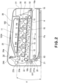
- Figure 2 is a sectional view of the image forming apparatus 100.
- the image forming apparatus 100 is a four color-based full-color laser printer using an electrophotographic process, and executes image formation on a recording material (sheet) on the basis of an electrical image signal inputted from an external host device (not shown) such as a personal computer or an image reader.
- a front side (front surface side) means the side where an apparatus opening/closing door 31 is provided.
- a rear side is the side opposite to the front side.
- a front-rear direction includes a frontward direction toward front as seen from the rear side of the apparatus main assembly 100A and a rearward direction opposite to the frontward direction.
- the left and right sides means the left and right sides as seen from the front side of the apparatus main assembly 100A.
- a left-right direction includes a leftward direction from right toward left as seen from the front side and a rightward direction opposite to the leftward direction.
- each cartridge P in this embodiment is prepared by integrally assembling an electrophotographic photosensitive drum 1 as a first image bearing member, and as process means acting on the drum 1, a charging device 2, a developing device 3 and the cleaning device 4, in a cartridge frame 5 ( Figures 7 and 8 ).
- the charging device 2 is contact charging roller, and in a developer container, a developer (toner) is accommodated.
- the cleaning device is of a blade type.
- the developing device 3 of the first cartridge PY accommodate yellow (Y) toner, and on the surface of the drum 1, a toner (developer) image of yellow (Y) is formed.
- the developing device 3 of the second cartridge PM accommodates magenta (M) toner, and on the surface of the drum 1, a toner image of magenta (M) is formed.
- the developing device 3 of the third cartridge PC accommodates cyan (C) toner, and on the surface of the drum 1, a toner image of cyan (C) is formed.
- the developing device 3 of the fourth cartridge PK accommodates black (K) toner, and on the surface of the drum 1, a toner image of black (K) is formed.
- a laser scanner unit 11 is provided above the cartridges P.
- This scanner unit 11 outputs laser light L modulated correspondingly to image information for each color inputted from the external host device to subject the drum surface of each cartridge P to scanning exposure through an exposure window 6 ( Figures 7 and 8 ) provided at an upper surface of the cartridge frame 5.
- the belt unit 12 includes, as an intermediary transfer member (second image bearing member), an endless belt which is formed of a dielectric material and which has flexibility, and includes a driving roller 14 and a tension roller 15 around which the belt 13 is extended and stretched to be moved and circulated.
- the driving roller 14 is disposed on the rear side of the apparatus main assembly 100A.
- the tension roller 15 is disposed on the front side of the apparatus main assembly 100A.
- the drum 1 of each cartridge P contacts, at its lower surface, an upper surface of an upper belt portion of the belt 13.
- four primary transfer rollers 17 are provided opposed to the drum 1 of the corresponding cartridge P through the upper belt portion of the belt 3.
- a secondary transfer roller 22 is contacted to the belt 13.
- a sheet feeding unit 18 is disposed, and includes a sheet feeding tray 19, a pick-up roller 60 as a feeding means, a feeding roller 20, and a separation roller 21, and the like.
- the sheet feeding tray 19 as a recording material accommodating portion can be finely inserted into and taken out from the apparatus main assembly 100A from the front side (front loading).
- the sheet feeding tray 19 is constituted so as to be movable in a direction crossing axes of the pick-up roller 60, the sheet feeding roller 20 and the separation roller 21.
- a stay 16 as a partitioning member is provided between the belt unit 12 and the sheet feeding unit 1.
- the stay 16 partitions the belt 13 and the sheet feeding unit 18 with respect to the vertical direction.
- a fixing device 23 and a sheet discharging roller pair 24 are provided at an upper portion in the rear side of the apparatus main assembly 100A. Further, an upper surface of the apparatus main assembly 100A is configured as a sheet discharging tray 25.
- the fixing device 23 includes a fixation film assembly 23a and a pressing roller 23b.
- the sheet discharging roller pair 24 includes sheet discharging rollers 24a and 24b.
- Each cartridge P in a state in which it is mounted in the apparatus main assembly 100A at a mounting position is held in a state in which each cartridge P is fixed at a predetermined positioning portion described later. Further, to a driving force input portion of the cartridge P, a driving force output portion of the apparatus main assembly 100A is connected. Further, to an electrical contact of the cartridge P, an electric energy supplying system of the apparatus main assembly 100A is electrically connected.
- An operation for forming a full-color image is as follows.
- the drum 1 of each of the first to fourth cartridges P is rotationally driven at a predetermined control speed. Further, also the belt 13 is rotationally driven.
- the scanner unit 11 is also driven. In synchronization with the driving of the scanner unit 11, the charging roller 2 in each cartridge P uniformly electrically charges the surface of the drum 1 to predetermined polarity and potential at predetermined control timing.
- the scanner unit 11 scans (exposes) the surface of each drum 1 with the laser light L modulated correspondingly to the image signal for an associated color. As a result, an electrostatic latent image corresponding to the image signal for the associated color is formed on the surface of the drum 1. T thus formed electrostatic latent image is developed by the developing device 3 into a toner image.
- a magenta toner image which corresponds to the magenta component of the full-color image is formed, and this toner image is primary-transferred onto the belt 13 so that it is superposed on the yellow toner image which has already been transferred on the belt 13.
- a cyan toner image which corresponds to the cyan component of the full-color image is formed, and this toner image is primary-transferred onto the belt 13 so that it is superposed on the yellow and magenta toner images which have already been transferred the belt 13.
- a black toner image which corresponds to the black component of the full-color image is formed, and this toner image is primary-transferred onto the belt 13 so that it is superposed on the yellow, magenta, and cyan toner images which have already been transferred on the belt 13.
- an unfixed full-color toner image is synthetically formed on the belt 13 by the yellow, magenta, cyan and black toner images.
- a transfer residual toner remaining on the surface of the drum 1 at each cartridge P is removed by the cleaning device 4.
- the pick-up roller 60 is rotationally driven at predetermined control timing.
- One of sheets Pa as the recording material stacked on the sheet feeding tray 19 is fed from an (one) end side of the sheet feeding tray 19 with respect to a feeding direction of the sheet Pa.
- the sheets Pa are separated and fed one by one by the sheet feeding roller 20 and the separation roller 21, thus being conveyed to a conveying roller pair 61 (61a, 61b).
- the conveying roller pair 61 conveys the sheet Pa to a nip (secondary transfer nip), between the secondary transfer roller 22 and the belt 13, which is a transfer position provided in a downstream side with respect to the feeding direction of the sheet Pa.
- the sheet Pa is separated from the surface of the belt 13 and introduced into the fixing device 23, and is heated and pressed in a fixing nip of the fixing device 23. As a result, color mixing of the respective color toner images and fixation thereof on the sheet Pa are performed. Thereafter, the sheet Pa is moved out of the fixing device 23, and then is discharged as a full-color image formation product onto the sheet discharge tray 25 by the sheet discharging roller pair 24.
- a secondary-transfer residual toner remaining on the surface of the belt 13 is, in this embodiment, electrostatically deposited on the drum 1 surface at the primary transfer portion of, e.g., the first process cartridge PY and is removed by the cleaning device 4.
- a cartridge exchanging (replacing) method will be described with reference to Figures 1 to 11 .
- the developer (toner) accommodated in the developing device 3 is consumed. Then, when the developer is consumed to such an extent that an image of a quality satisfactory to a user who has purchased the cartridge P cannot be formed, the exchange of the cartridge P is required.
- the image forming apparatus is provided with a means (not shown) for detecting an amount of the developer remaining in individual cartridge P.
- the detected amount of the developer in each cartridge P is compared, by the controller, with a threshold (value) preset for providing a prewarning or warning of its lifetime of the cartridge P.
- a threshold value preset for providing a prewarning or warning of its lifetime of the cartridge P.
- the prewarning or warning of the lifetime of the cartridge P is displayed on a display portion.
- the image forming apparatus prompts the user to prepare a cartridge for exchange, or to replace the cartridge P with a fresh cartridge, in order to maintain an output image quality.
- the exchange (replacement) of the cartridge P is performed through a method in which the cartridge P is placed on a tray to be pulled out and then is replaced in a front-access manner in order to improve usability.
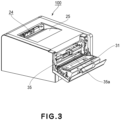
- an opening 30 ( Figure 2 ) through which the cartridge P passes in order that the cartridge P is inserted into the apparatus main assembly 100A and is taken out from the apparatus main assembly 100A is provided.
- a door (opening/closing member) 31 movable between a closing position where the opening 30 is closed and an opening position where the opening 30 is open.
- the door 31 can be opened and closed and can be rotationally moved relative to the apparatus main assembly 100A about a horizontal (lateral) shaft (hinge shaft) 32 provided at a lower portion of the door 31. That is, the door 31 is rotated about the hinge shaft 32 so that it can be placed in a closed state with respect to the apparatus main assembly 100 as shown in Figures 1 and 2 .
- the opening 30 is closed.
- the door 31 is rotated frontward with respect to the apparatus main assembly 100a, about the hinge shaft 32 so that it can be placed in an open state from the apparatus main assembly 100A as shown in Figures 3 and 4 .
- a finger placement portion 31a for opening/closing the door 31 is provided to the door 31.
- a cartridge tray 35 as a cartridge supporting member is held slidably movable in arrow D1 and D2 directions.
- the movement direction of the tray 35 is constituted so that the tray 35 is, similarly as in the case of the sheet feeding tray 19, movable in the direction crossing the axes of the pick-up roller 60, the sheet feeding roller 20 and the separation roller 21.
- positioning accuracy is improved by ease of ensuring of dimensional accuracy and a small amount of deformation due to thermal expansion.
- a constitution for enabling such arrangement of the positioning shape portion 35g and the tray positioning shape portion 47 will be described later.
- the tray 35 is pulled out sufficiently through the opening 30 to a mounting and demounting position located outside the apparatus main assembly 100A.
- the entire four (first to fourth) cartridges P held by the tray 35 pass through the opening 30 and are exposed to the outside of the apparatus main assembly 100A, so that upper (top) surfaces of all the cartridge P are exposed.
- the tray 35 is pulled out by a sufficient predetermined distance, the tray 35 is prevented by an unshown stopper portion from being pulled out further.
- the tray 35 is held in a predetermined mounting and demounting position state by a tray holding rail and the door 31.
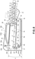
- the tray 35 supports each cartridge P so as to be detachably movable upward (in an arrow C1 direction). Further, the tray 35 supports each cartridge P by moving each carriage P downward (in an arrow C2 direction). As shown by a broken line in Figure 6 , a spent cartridge P to be replaced is raised and removed above from the tray 35 in the arrow C1 direction. Then, a fresh cartridge P is engaged in and placed on the tray 35 from above.
- the tray 35 is the movable member provided movably in the direction crossing the axial direction of the drum 1 of each cartridge P. Further, the tray 35 is moved to a mounting and demounting position ( Figure 6 ), an image forming position ( Figure 2 ) and an inside position ( Figure 4 ). At the mounting and demounting position ( Figure 6 ), each cartridge P is detachably mountable to the apparatus main assembly 100A in the outside of the apparatus main assembly 100A. At the image forming portion ( Figure 2 ), the electrostatic latent image can be formed on the drum 1 and further the drum 1 contacts the belt 13 and thus the developer image formed on the drum 1 is transferable onto the belt 13.
- the tray 35 is moved upward from the image forming position and can be made movable between the inside position of the apparatus main assembly A and the mounting and demounting position in a state in which the drum 1 is spaced from the belt 13.
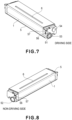
- Figures 7 and 8 are perspective views each showing an outer appearance of the cartridge.
- Figure 7 is the perspective view as seen from a driving side
- Figure 8 is the perspective view as seen from a non-driving side.
- the cartridge is an assembly having a laterally elongated box-like shape in which the axial direction of the drum 1 is the left-right direction which is a longitudinal direction.
- the drum 1 is provided and supported rotatably between bearing portions 51 and 52 which are provided at a right-side surface portion and a left-side surface portion, respectively, of the cartridge frame 5.
- the right-side bearing portion 51 is provided with a coupling engaging portion 53 as a drum-driving force inputting portion.
- a coupling engaging portion 54 as a developing roller-driving force inputting portion for driving the developing roller 3a is provided at the right-side surface portion.
- the side where the coupling engaging portions 53 and 54 are provided is the driving side
- the left-side surface portion in an opposite side to the driving side is the non-driving side
- the cartridge is provided with a rotation stopper 57 and a projection 56 in each of the left and right sides.
- Figure 9 is a perspective view of an outer appearance of the tray 35.
- the tray 35 includes a rectangular large frame portion, and the inside of the large frame portion is substantially equally partitioned into four areas by three partitioning plates 35b with respect to the front-rear direction thereof, so that first to fourth elongated small frame portions 35(1) to 35(4) from a rear frame plate 35c side to a front frame plate 35b side are formed in this order.
- Each of the small frame portions 35(1) to 35(4) is a portion where the cartridge P is to be held.
- bearing portion 37 and a groove (slot) 36 are provided in each of the left and right sides of each of the small frame portions 35(1) to 35(4).
- Figure 10 and 11 are schematic views each for illustrating a state in which each cartridge P is mounted in a pulled-out state of the tray 35 shown in Figure 5 .
- the bearing portion 52 of the cartridge P contacts the bearing portion 37, so that the cartridge P is supported.
- the projection 56 of the cartridge P enters the groove 36 to stop rotation of the cartridge P. However, there is play between the projection 56 and the groove 36, so that the cartridge P is held rotatably correspondingly to the play.
- FIG 12 is a perspective view showing a state the door 31 is opened and the inside of the apparatus main assembly 100A is seen from the opening 35 side in a state in which the tray 35 is removed, wherein a side plate 41 is provided with rotation stopper shape portions 42 at four positions corresponding to the cartridge P. Further, in alignment with the rotation stopper shape portions 42, a tray positioning shape portion 47 for positioning the tray 35 is provided. Similarly, also a side plate in the opposite side is provided with the four rotation stopper shape portion 42 and the tray positioning shape portion 47 (not shown).
- the door 31 is provided with an arm member 33, and the side plate 41 is provided with a cam plate 44, and a slidable plate 43 is provided movably on the cam plate 44 in the front-rear direction.
- the slidable plate 43 is moved in the front-rear direction by the arm member 33 ((a) and (b) of Figure13 ).
- Parts (a) and (b) of Figure 14 are perspective views each showing a state in which the cam plate 44 and its peripheral portion are extracted, and the door 31 and the side plate 41 are omitted from illustration.
- a rail 45 and a positioning plate 46 are provided inside the side plate (not shown).
- the positioning plate 46 constitutes a part of a main assembly casing of the image forming apparatus 100 similarly as the side plate 41 and is provided with a positioning portion 46a.
- the rail 45 is provided with bosses 45a and 45b, and enters a cam shape portion 44a of the cam plate 44 through a hole (not shown), and further the boss 45a is inserted into a hole 43a of the slidable plate 43.
- the state of the door 31 (not shown) is changed from an open state of (a) of Figure 14 to a closed state of (b) of Figure 14 , so that the arm member 33 is rotated to move the slidable plate 43 rearward, thus pushing the boss 45a of the rail 45 to move the rail 45 rearward.
- Parts (a) and (b) of Figure 15 are sectional views each showing a state of a combination of the tray 35 and the cartridge P, and (a) and (b) of Figure 15 are side views each showing the state of the combination of the tray 35 and the cartridges P, in which (a) of each of Figures 14 and 15 shows the open state of the portion 31, and (b) of each of Figures 14 and 15 shows the closed state.
- the tray 35 is supported by the rail 45 at its left and right ends, and is moved upward and downward with raising and lowering of the rail 45 in a state a pulling-out direction of the tray 35 is positionally determined by the tray positioning shape portion 47, and the positioning shape portion 35g and stopper claw 35f on the tray 35 ( Figure 17 ). From the state of (a) of each of Figures 15 and 16 , the portion 31 is closed, so that the tray 35 and the cartridges P mounted on the tray 35 are lowered to the state of (b) of each of the Figures 15 and 16 . Thus, the bearing portion 52 of the cartridge P is engaged with the positioning portion 46a of the positioning plate 46.
- the rotation stopper 57 is engaged with the rotation stopper shape portion 42 to stop the rotation of the cartridge P, so that the positioning of the cartridge P relative to the apparatus main assembly 100A and the stop of the rotation of the cartridge P are completed.
- a lowering amount of the rail 45 is set so that the tray 35 can be lowered even after the bearing portion 52 of the cartridge P is engaged with the positioning portion 46a of the positioning plate 46 to stop the lowering of the tray 35.
- a gap is created between the bearing portion 37 of the tray 35 and the bearing portion 52 of the cartridge P, so that the positioning of the cartridge P is prevented from being adversely affected.
- play is provided also between the groove 36 of the tray 35 and the projection 56 of the cartridge P.
- a guidable amount of the play is set so that the rotation stopper 57 can be engaged with the rotation stopper shape portion 42 during the lowering of the tray 35 and the cartridge P.
- the above description was made with respect to the non-driving side, but the same constitution is employed also in the driving side.
- the rotation stopper shape portion 42 and the tray positioning shape portion 47 are cylindrical bosses and are metal shafts which are clamped to the side plates 40 and 41.
- the portions 42 and 47 can also be a shape portion 42a formed by bending the side plates 40 and 41, thus reducing the number of parts to realize cost reduction.
- the rotation stopper is provided in both the driving side and the non-driving side.
- the rotation stopper may also be provided in either one side if the process cartridge has sufficient rigidity and can hold its attribute by itself. That is, as in this embodiment, the constitution in which the rotation stopper is provided in both sides to decrease the rigidity of the process cartridge as a member to be exchanged (replaced), thus realizing the cost reduction may also be employed.
- the rail 45 was constituted so that it had the above-described shape portions only at a lower portion of the tray 35 but had not the shape portions between the tray 35 or the process cartridge and each of the side plates 40 and 41.
- the cartridges P are disposed in an inclined state with respect to the front-rear direction.
- the belt 13 was used as the intermediary transfer member.
- the mounting and demounting mechanism of the process cartridge can be similarly realized in this embodiment.
- a mounting and demounting operation is performed by the moving operation of the tray 35 in the arrangement direction of the cartridges P, a height necessary for the operation is prevented from being increased by providing a cover or the like for being opened upward and being closed during not only the image formation but also the exchange of the cartridge. Further, while providing an easy process cartridge exchanging means through the operation of the apparatus main assembly 100A from the front surface, the positioning and rotation stop of each cartridge P during the image formation can be performed with high accuracy the image forming apparatus main assembly 100A without via the tray 35. (Inclined arrangement of tray)
- the rail 45 is provided with an inclined portion having an inclination angle ⁇ with respect to the horizontal direction.
- the rail 45 is provided in the apparatus main assembly 100A so as to be located above with respect to the vertical direction in a side in the neighborhood of the opening/closing door 31 and be located below with respect to the vertical direction in the rear side of the apparatus main assembly 100A is an obliquely inclined state. Further, also the tray 35 movably supported by the rail 45 is in the inclined state with the angle ⁇ with respect to the horizontal direction at the image forming position and the inside position.
- the tray 35 is, at the image forming position and the inside position, in a state in which a portion of the tray in a side opposing, with respect to the vertical direction, another side of the sheet feeding tray 19 with respect to the feeding direction is lower (in height) than a portion of the tray 35 in a side opposing a (one) side of the sheet feeding tray 19 with respect to the vertical direction.
- the tray 35 is pulled out, as shown in Figure 6 , the tray 35 is moved so as to be slid obliquely downward along the rail 49. Further, the tray 35 is moved to the mounting and demounting position in a state in which the inclination angle ⁇ is maintained.
- the cartridges PY and PM which are disposed in the upstream side with respect to the pulling-out direction of the tray 35 are in a state in which the cartridges are easily mounted and demounted.
- the rail 45 is somewhat translated upward in interrelation with the opening/closing door 31 in order to space the drum 1 from the belt 13, but the inclination angle of the rail 45 is not changed, so that there is no generation of a large dead space.
- the stay 16 as the partitioning member is inclined in the same direction as that of the rail 45.
- the inclination angle of the stay 16 is not required to be made equal to the inclination angle ⁇ of a guide rail 24 but may only be required to have the same inclination direction.
- members such as the belt 13 and the scanner unit 11 which are provided above the stay 16 are provided in an inclined state with respect to the same direction with the angle ⁇ .
- the inclination direction of the upper surface 26 is the same as those of the rail 45, the stay 16 and the like.
- a space 227 between a state feeding cassette 202 and the stay 216 there was a space 227 between a state feeding cassette 202 and the stay 216.
- the space 227 is not used for some purpose but constitutes the dead space. That is, a sheet feeding portion constituted by a sheet feeding roller 203, a separation roller 204, a conveying roller 205 and the like is required to be provided above a bundle of sheets Pa stacked in the sheet feeding cassette 202 by any means in the constitution. Further, there is a need to provide a transfer portion, constituted by an intermediary transfer belt 211, a secondary transfer belt 213 and the like, above the sheet feeding portion.
- the space 227 had to be provided between the sheet feeding cassette 202 and the intermediary transfer belt 211.
- the sheet feeding portion is downsized in the up-down direction, but when the sheet feeding portion is excessively downsized, curvature of a conveying path of the sheet Pa becomes large, so that there is a possibility that the downsized sheet feeding portion adversely affects a feeding performance of the sheet Pa.
- a broken line indicated at an upper right portion of the image forming apparatus 100 in Figure 2 shows a contour of a casing of the conventional image forming apparatus.
- this contour is compared with a contour of the image forming apparatus 100 in this embodiment, it is understood that the casing of the image forming apparatus 100 in this embodiment is downsized compared with that of the conventional image forming apparatus by an amount corresponding to the space at the upper right portion on the upper surface 26 of the image forming apparatus 100.
- the four cartridges P are mounted on the tray 35.
- a force such that the tray 35 is slid downward along the inclined portion is applied by the self-weight of the cartridges P. The force assists the pulling-out operation, so that an operating force when the tray 35 is pulled out is reduced.
- a rear-side end portion 16b of the stay 16 was disposed above an upper outer-diameter portion of the conveying roller pair 61. This is similar to that in the conventional image forming apparatus. However, a front-side end portion 16a of the stay 16 is disposed below a lower outer-diameter portion of the conveying roller pair 61 with respect to the vertical direction. That is, a horizontal line H passing through the front-side end portion 16a of the stay 16 in Figure 2 passes below the lower outer-diameter portion of the conveying roller pair 61.
- a value of the inclination angle ⁇ of the rail 45 is not particularly limited.
- the cartridge P supported by the tray 35 was described by using the process cartridge.
- a drum cartridge for supporting the drum 1 and the developing cartridge for supporting the developing roller 3 may also be supported by the tray 35 as separate members.
- a constitution in which the drum 1 is directly supported by the tray 35 and the developing cartridge for supporting the developing roller 3 is detachably mountable to the tray 35 may also be employed.
- the image forming apparatus can be downsized by effectively using a space above an accommodating portion, with respect to the vertical direction, for accommodating the recording material.
Landscapes
- Physics & Mathematics (AREA)
- General Physics & Mathematics (AREA)
- Engineering & Computer Science (AREA)
- Computer Vision & Pattern Recognition (AREA)
- Electrophotography Configuration And Component (AREA)
- Color Electrophotography (AREA)
Priority Applications (1)
| Application Number | Priority Date | Filing Date | Title |
|---|---|---|---|
| EP24211705.9A EP4495703A3 (en) | 2012-05-21 | 2013-05-14 | Image forming apparatus |
Applications Claiming Priority (2)
| Application Number | Priority Date | Filing Date | Title |
|---|---|---|---|
| JP2012115845A JP6128754B2 (ja) | 2012-05-21 | 2012-05-21 | 画像形成装置 |
| EP13167641.3A EP2667263B1 (en) | 2012-05-21 | 2013-05-14 | Image forming apparatus |
Related Parent Applications (2)
| Application Number | Title | Priority Date | Filing Date |
|---|---|---|---|
| EP13167641.3A Division EP2667263B1 (en) | 2012-05-21 | 2013-05-14 | Image forming apparatus |
| EP13167641.3A Division-Into EP2667263B1 (en) | 2012-05-21 | 2013-05-14 | Image forming apparatus |
Related Child Applications (2)
| Application Number | Title | Priority Date | Filing Date |
|---|---|---|---|
| EP24211705.9A Division EP4495703A3 (en) | 2012-05-21 | 2013-05-14 | Image forming apparatus |
| EP24211705.9A Division-Into EP4495703A3 (en) | 2012-05-21 | 2013-05-14 | Image forming apparatus |
Publications (2)
| Publication Number | Publication Date |
|---|---|
| EP3992726A1 EP3992726A1 (en) | 2022-05-04 |
| EP3992726B1 true EP3992726B1 (en) | 2024-12-18 |
Family
ID=48576722
Family Applications (3)
| Application Number | Title | Priority Date | Filing Date |
|---|---|---|---|
| EP21198776.3A Active EP3992726B1 (en) | 2012-05-21 | 2013-05-14 | Image forming apparatus |
| EP13167641.3A Active EP2667263B1 (en) | 2012-05-21 | 2013-05-14 | Image forming apparatus |
| EP24211705.9A Pending EP4495703A3 (en) | 2012-05-21 | 2013-05-14 | Image forming apparatus |
Family Applications After (2)
| Application Number | Title | Priority Date | Filing Date |
|---|---|---|---|
| EP13167641.3A Active EP2667263B1 (en) | 2012-05-21 | 2013-05-14 | Image forming apparatus |
| EP24211705.9A Pending EP4495703A3 (en) | 2012-05-21 | 2013-05-14 | Image forming apparatus |
Country Status (6)
| Country | Link |
|---|---|
| US (1) | US9052688B2 (https=) |
| EP (3) | EP3992726B1 (https=) |
| JP (1) | JP6128754B2 (https=) |
| KR (1) | KR101721013B1 (https=) |
| CN (1) | CN103425021B (https=) |
| RU (1) | RU2549217C2 (https=) |
Families Citing this family (19)
| Publication number | Priority date | Publication date | Assignee | Title |
|---|---|---|---|---|
| JP6128754B2 (ja) | 2012-05-21 | 2017-05-17 | キヤノン株式会社 | 画像形成装置 |
| US9158221B2 (en) * | 2012-12-27 | 2015-10-13 | Brother Kogyo Kabushiki Kaisha | Removable waste toner storage configuration for an image forming apparatus |
| JP6278665B2 (ja) * | 2013-11-20 | 2018-02-14 | キヤノン株式会社 | 画像形成装置 |
| JP6395490B2 (ja) * | 2014-07-30 | 2018-09-26 | キヤノン株式会社 | 画像形成装置 |
| JP6432375B2 (ja) | 2015-02-06 | 2018-12-05 | ブラザー工業株式会社 | 画像形成装置 |
| JP6409602B2 (ja) | 2015-02-06 | 2018-10-24 | ブラザー工業株式会社 | 画像形成装置および移動部材 |
| JP6390457B2 (ja) | 2015-02-06 | 2018-09-19 | ブラザー工業株式会社 | 画像形成装置 |
| JP6481395B2 (ja) | 2015-02-06 | 2019-03-13 | ブラザー工業株式会社 | 画像形成装置 |
| JP6428332B2 (ja) | 2015-02-06 | 2018-11-28 | ブラザー工業株式会社 | 画像形成装置 |
| JP6409603B2 (ja) | 2015-02-06 | 2018-10-24 | ブラザー工業株式会社 | 画像形成装置 |
| JP6414480B2 (ja) | 2015-02-06 | 2018-10-31 | ブラザー工業株式会社 | 画像形成装置 |
| JP6946628B2 (ja) | 2016-09-30 | 2021-10-06 | ブラザー工業株式会社 | 画像形成装置 |
| JP6972531B2 (ja) | 2016-10-18 | 2021-11-24 | ブラザー工業株式会社 | 画像形成装置 |
| JP6849396B2 (ja) * | 2016-11-01 | 2021-03-24 | キヤノン株式会社 | 画像形成装置 |
| WO2019027424A2 (en) * | 2017-07-31 | 2019-02-07 | Hewlett-Packard Development Company, L.P. | PLATE COVER EXTENSION DEVICES |
| KR102323007B1 (ko) | 2018-01-22 | 2021-11-10 | 휴렛-팩커드 디벨롭먼트 컴퍼니, 엘.피. | 트레이에 소모품 카트리지 장착을 위한 가이드 부재를 포함하는 화상형성장치 |
| US10656592B1 (en) * | 2019-01-09 | 2020-05-19 | Lexmark International, Inc. | Toner cartridge having positioning features |
| JP7362289B2 (ja) | 2019-04-10 | 2023-10-17 | キヤノン株式会社 | 画像形成装置 |
| JP7347029B2 (ja) * | 2019-09-02 | 2023-09-20 | ブラザー工業株式会社 | 画像形成装置 |
Family Cites Families (15)
| Publication number | Priority date | Publication date | Assignee | Title |
|---|---|---|---|---|
| JP3094229B2 (ja) | 1990-08-28 | 2000-10-03 | コニカ株式会社 | カラー画像形成装置 |
| JP2005107109A (ja) * | 2003-09-30 | 2005-04-21 | Minolta Co Ltd | 画像形成装置 |
| JP4134985B2 (ja) * | 2004-12-27 | 2008-08-20 | ブラザー工業株式会社 | 画像形成装置、及びカートリッジ |
| BR122018006712B1 (pt) | 2005-03-04 | 2019-08-20 | Canon Kabushiki Kaisha | Recipiente de suprimento de revelador e sistema de suprimento de revelador |
| JP4298669B2 (ja) * | 2005-03-16 | 2009-07-22 | キヤノン株式会社 | 画像形成装置 |
| JP4626370B2 (ja) * | 2005-04-11 | 2011-02-09 | ブラザー工業株式会社 | 画像形成装置 |
| JP4769699B2 (ja) | 2006-01-11 | 2011-09-07 | キヤノン株式会社 | 電子写真画像形成装置 |
| JP4508273B2 (ja) * | 2008-06-30 | 2010-07-21 | ブラザー工業株式会社 | 画像形成装置 |
| JP4459295B1 (ja) | 2008-09-29 | 2010-04-28 | キヤノン株式会社 | カラー電子写真画像形成装置 |
| JP4916557B2 (ja) * | 2008-09-29 | 2012-04-11 | キヤノン株式会社 | カラー電子写真画像形成装置 |
| JP4689750B2 (ja) * | 2008-09-29 | 2011-05-25 | キヤノン株式会社 | 電子写真画像形成装置 |
| JP5051118B2 (ja) | 2008-12-24 | 2012-10-17 | ブラザー工業株式会社 | 画像形成装置 |
| JP4916523B2 (ja) * | 2009-03-19 | 2012-04-11 | キヤノン株式会社 | 画像形成装置 |
| JP5821331B2 (ja) * | 2011-06-30 | 2015-11-24 | ブラザー工業株式会社 | 画像形成装置 |
| JP6128754B2 (ja) | 2012-05-21 | 2017-05-17 | キヤノン株式会社 | 画像形成装置 |
-
2012
- 2012-05-21 JP JP2012115845A patent/JP6128754B2/ja active Active
-
2013
- 2013-05-14 EP EP21198776.3A patent/EP3992726B1/en active Active
- 2013-05-14 EP EP13167641.3A patent/EP2667263B1/en active Active
- 2013-05-14 EP EP24211705.9A patent/EP4495703A3/en active Pending
- 2013-05-15 US US13/894,473 patent/US9052688B2/en active Active
- 2013-05-20 KR KR1020130056355A patent/KR101721013B1/ko active Active
- 2013-05-20 RU RU2013123016/28A patent/RU2549217C2/ru active
- 2013-05-21 CN CN201310188510.1A patent/CN103425021B/zh active Active
Also Published As
| Publication number | Publication date |
|---|---|
| US20130308976A1 (en) | 2013-11-21 |
| EP4495703A3 (en) | 2025-04-23 |
| CN103425021B (zh) | 2017-05-10 |
| EP4495703A2 (en) | 2025-01-22 |
| EP3992726A1 (en) | 2022-05-04 |
| EP2667263A3 (en) | 2017-07-26 |
| KR101721013B1 (ko) | 2017-03-29 |
| RU2013123016A (ru) | 2014-11-27 |
| JP6128754B2 (ja) | 2017-05-17 |
| JP2013242439A (ja) | 2013-12-05 |
| KR20130129847A (ko) | 2013-11-29 |
| EP2667263A2 (en) | 2013-11-27 |
| EP2667263B1 (en) | 2021-11-03 |
| RU2549217C2 (ru) | 2015-04-20 |
| US9052688B2 (en) | 2015-06-09 |
| CN103425021A (zh) | 2013-12-04 |
Similar Documents
| Publication | Publication Date | Title |
|---|---|---|
| EP3992726B1 (en) | Image forming apparatus | |
| EP2592496B1 (en) | Image forming apparatus and cartridge | |
| EP2069869B1 (en) | Electrophotographic image forming apparatus | |
| US7773911B2 (en) | Electrophotographic image forming apparatus having a drawing member positionable at mount and drawn positions for mounting plural process cartridges | |
| US8442412B2 (en) | Electrophotographic color image forming apparatus carrying process cartridges on a movable member | |
| US8290395B2 (en) | Electrophotographic image forming apparatus | |
| US10108141B2 (en) | Electrophotographic image forming apparatus, process cartridge and developing cartridge | |
| US8437660B2 (en) | Image forming apparatus with movable member for supporting cartridges | |
| US9069329B2 (en) | Image forming apparatus | |
| EP2945023B1 (en) | Image forming apparatus | |
| US8204404B2 (en) | Image forming apparatus | |
| US9223242B2 (en) | Image forming apparatus |
Legal Events
| Date | Code | Title | Description |
|---|---|---|---|
| PUAI | Public reference made under article 153(3) epc to a published international application that has entered the european phase |
Free format text: ORIGINAL CODE: 0009012 |
|
| STAA | Information on the status of an ep patent application or granted ep patent |
Free format text: STATUS: THE APPLICATION HAS BEEN PUBLISHED |
|
| AC | Divisional application: reference to earlier application |
Ref document number: 2667263 Country of ref document: EP Kind code of ref document: P |
|
| AK | Designated contracting states |
Kind code of ref document: A1 Designated state(s): AL AT BE BG CH CY CZ DE DK EE ES FI FR GB GR HR HU IE IS IT LI LT LU LV MC MK MT NL NO PL PT RO RS SE SI SK SM TR |
|
| STAA | Information on the status of an ep patent application or granted ep patent |
Free format text: STATUS: REQUEST FOR EXAMINATION WAS MADE |
|
| 17P | Request for examination filed |
Effective date: 20221104 |
|
| RBV | Designated contracting states (corrected) |
Designated state(s): AL AT BE BG CH CY CZ DE DK EE ES FI FR GB GR HR HU IE IS IT LI LT LU LV MC MK MT NL NO PL PT RO RS SE SI SK SM TR |
|
| GRAP | Despatch of communication of intention to grant a patent |
Free format text: ORIGINAL CODE: EPIDOSNIGR1 |
|
| STAA | Information on the status of an ep patent application or granted ep patent |
Free format text: STATUS: GRANT OF PATENT IS INTENDED |
|
| INTG | Intention to grant announced |
Effective date: 20240229 |
|
| RAP3 | Party data changed (applicant data changed or rights of an application transferred) |
Owner name: CANON KABUSHIKI KAISHA |
|
| RIN1 | Information on inventor provided before grant (corrected) |
Inventor name: SEKIDO, KOTA |
|
| GRAJ | Information related to disapproval of communication of intention to grant by the applicant or resumption of examination proceedings by the epo deleted |
Free format text: ORIGINAL CODE: EPIDOSDIGR1 |
|
| STAA | Information on the status of an ep patent application or granted ep patent |
Free format text: STATUS: REQUEST FOR EXAMINATION WAS MADE |
|
| GRAP | Despatch of communication of intention to grant a patent |
Free format text: ORIGINAL CODE: EPIDOSNIGR1 |
|
| STAA | Information on the status of an ep patent application or granted ep patent |
Free format text: STATUS: GRANT OF PATENT IS INTENDED |
|
| INTC | Intention to grant announced (deleted) | ||
| INTG | Intention to grant announced |
Effective date: 20240711 |
|
| GRAS | Grant fee paid |
Free format text: ORIGINAL CODE: EPIDOSNIGR3 |
|
| GRAA | (expected) grant |
Free format text: ORIGINAL CODE: 0009210 |
|
| STAA | Information on the status of an ep patent application or granted ep patent |
Free format text: STATUS: THE PATENT HAS BEEN GRANTED |
|
| AC | Divisional application: reference to earlier application |
Ref document number: 2667263 Country of ref document: EP Kind code of ref document: P |
|
| AK | Designated contracting states |
Kind code of ref document: B1 Designated state(s): AL AT BE BG CH CY CZ DE DK EE ES FI FR GB GR HR HU IE IS IT LI LT LU LV MC MK MT NL NO PL PT RO RS SE SI SK SM TR |
|
| REG | Reference to a national code |
Ref country code: CH Ref legal event code: EP |
|
| REG | Reference to a national code |
Ref country code: DE Ref legal event code: R096 Ref document number: 602013086390 Country of ref document: DE |
|
| REG | Reference to a national code |
Ref country code: IE Ref legal event code: FG4D |
|
| REG | Reference to a national code |
Ref country code: LT Ref legal event code: MG9D |
|
| PG25 | Lapsed in a contracting state [announced via postgrant information from national office to epo] |
Ref country code: HR Free format text: LAPSE BECAUSE OF FAILURE TO SUBMIT A TRANSLATION OF THE DESCRIPTION OR TO PAY THE FEE WITHIN THE PRESCRIBED TIME-LIMIT Effective date: 20241218 |
|
| PG25 | Lapsed in a contracting state [announced via postgrant information from national office to epo] |
Ref country code: FI Free format text: LAPSE BECAUSE OF FAILURE TO SUBMIT A TRANSLATION OF THE DESCRIPTION OR TO PAY THE FEE WITHIN THE PRESCRIBED TIME-LIMIT Effective date: 20241218 |
|
| PG25 | Lapsed in a contracting state [announced via postgrant information from national office to epo] |
Ref country code: BG Free format text: LAPSE BECAUSE OF FAILURE TO SUBMIT A TRANSLATION OF THE DESCRIPTION OR TO PAY THE FEE WITHIN THE PRESCRIBED TIME-LIMIT Effective date: 20241218 |
|
| PG25 | Lapsed in a contracting state [announced via postgrant information from national office to epo] |
Ref country code: NO Free format text: LAPSE BECAUSE OF FAILURE TO SUBMIT A TRANSLATION OF THE DESCRIPTION OR TO PAY THE FEE WITHIN THE PRESCRIBED TIME-LIMIT Effective date: 20250318 |
|
| REG | Reference to a national code |
Ref country code: NL Ref legal event code: MP Effective date: 20241218 |
|
| PG25 | Lapsed in a contracting state [announced via postgrant information from national office to epo] |
Ref country code: LV Free format text: LAPSE BECAUSE OF FAILURE TO SUBMIT A TRANSLATION OF THE DESCRIPTION OR TO PAY THE FEE WITHIN THE PRESCRIBED TIME-LIMIT Effective date: 20241218 Ref country code: GR Free format text: LAPSE BECAUSE OF FAILURE TO SUBMIT A TRANSLATION OF THE DESCRIPTION OR TO PAY THE FEE WITHIN THE PRESCRIBED TIME-LIMIT Effective date: 20250319 |
|
| PG25 | Lapsed in a contracting state [announced via postgrant information from national office to epo] |
Ref country code: RS Free format text: LAPSE BECAUSE OF FAILURE TO SUBMIT A TRANSLATION OF THE DESCRIPTION OR TO PAY THE FEE WITHIN THE PRESCRIBED TIME-LIMIT Effective date: 20250318 |
|
| PG25 | Lapsed in a contracting state [announced via postgrant information from national office to epo] |
Ref country code: NL Free format text: LAPSE BECAUSE OF FAILURE TO SUBMIT A TRANSLATION OF THE DESCRIPTION OR TO PAY THE FEE WITHIN THE PRESCRIBED TIME-LIMIT Effective date: 20241218 |
|
| REG | Reference to a national code |
Ref country code: AT Ref legal event code: MK05 Ref document number: 1752721 Country of ref document: AT Kind code of ref document: T Effective date: 20241218 |
|
| PG25 | Lapsed in a contracting state [announced via postgrant information from national office to epo] |
Ref country code: SM Free format text: LAPSE BECAUSE OF FAILURE TO SUBMIT A TRANSLATION OF THE DESCRIPTION OR TO PAY THE FEE WITHIN THE PRESCRIBED TIME-LIMIT Effective date: 20241218 |
|
| PG25 | Lapsed in a contracting state [announced via postgrant information from national office to epo] |
Ref country code: PL Free format text: LAPSE BECAUSE OF FAILURE TO SUBMIT A TRANSLATION OF THE DESCRIPTION OR TO PAY THE FEE WITHIN THE PRESCRIBED TIME-LIMIT Effective date: 20241218 |
|
| PGFP | Annual fee paid to national office [announced via postgrant information from national office to epo] |
Ref country code: DE Payment date: 20250423 Year of fee payment: 13 |
|
| PG25 | Lapsed in a contracting state [announced via postgrant information from national office to epo] |
Ref country code: ES Free format text: LAPSE BECAUSE OF FAILURE TO SUBMIT A TRANSLATION OF THE DESCRIPTION OR TO PAY THE FEE WITHIN THE PRESCRIBED TIME-LIMIT Effective date: 20241218 |
|
| PG25 | Lapsed in a contracting state [announced via postgrant information from national office to epo] |
Ref country code: IS Free format text: LAPSE BECAUSE OF FAILURE TO SUBMIT A TRANSLATION OF THE DESCRIPTION OR TO PAY THE FEE WITHIN THE PRESCRIBED TIME-LIMIT Effective date: 20250418 |
|
| PG25 | Lapsed in a contracting state [announced via postgrant information from national office to epo] |
Ref country code: PT Free format text: LAPSE BECAUSE OF FAILURE TO SUBMIT A TRANSLATION OF THE DESCRIPTION OR TO PAY THE FEE WITHIN THE PRESCRIBED TIME-LIMIT Effective date: 20250421 |
|
| PG25 | Lapsed in a contracting state [announced via postgrant information from national office to epo] |
Ref country code: EE Free format text: LAPSE BECAUSE OF FAILURE TO SUBMIT A TRANSLATION OF THE DESCRIPTION OR TO PAY THE FEE WITHIN THE PRESCRIBED TIME-LIMIT Effective date: 20241218 |
|
| PGFP | Annual fee paid to national office [announced via postgrant information from national office to epo] |
Ref country code: FR Payment date: 20250423 Year of fee payment: 13 |
|
| PG25 | Lapsed in a contracting state [announced via postgrant information from national office to epo] |
Ref country code: RO Free format text: LAPSE BECAUSE OF FAILURE TO SUBMIT A TRANSLATION OF THE DESCRIPTION OR TO PAY THE FEE WITHIN THE PRESCRIBED TIME-LIMIT Effective date: 20241218 Ref country code: AT Free format text: LAPSE BECAUSE OF FAILURE TO SUBMIT A TRANSLATION OF THE DESCRIPTION OR TO PAY THE FEE WITHIN THE PRESCRIBED TIME-LIMIT Effective date: 20241218 |
|
| PG25 | Lapsed in a contracting state [announced via postgrant information from national office to epo] |
Ref country code: SK Free format text: LAPSE BECAUSE OF FAILURE TO SUBMIT A TRANSLATION OF THE DESCRIPTION OR TO PAY THE FEE WITHIN THE PRESCRIBED TIME-LIMIT Effective date: 20241218 |
|
| PG25 | Lapsed in a contracting state [announced via postgrant information from national office to epo] |
Ref country code: CZ Free format text: LAPSE BECAUSE OF FAILURE TO SUBMIT A TRANSLATION OF THE DESCRIPTION OR TO PAY THE FEE WITHIN THE PRESCRIBED TIME-LIMIT Effective date: 20241218 |
|
| PG25 | Lapsed in a contracting state [announced via postgrant information from national office to epo] |
Ref country code: IT Free format text: LAPSE BECAUSE OF FAILURE TO SUBMIT A TRANSLATION OF THE DESCRIPTION OR TO PAY THE FEE WITHIN THE PRESCRIBED TIME-LIMIT Effective date: 20241218 |
|
| PG25 | Lapsed in a contracting state [announced via postgrant information from national office to epo] |
Ref country code: SE Free format text: LAPSE BECAUSE OF FAILURE TO SUBMIT A TRANSLATION OF THE DESCRIPTION OR TO PAY THE FEE WITHIN THE PRESCRIBED TIME-LIMIT Effective date: 20241218 |
|
| REG | Reference to a national code |
Ref country code: DE Ref legal event code: R097 Ref document number: 602013086390 Country of ref document: DE |
|
| PG25 | Lapsed in a contracting state [announced via postgrant information from national office to epo] |
Ref country code: DK Free format text: LAPSE BECAUSE OF FAILURE TO SUBMIT A TRANSLATION OF THE DESCRIPTION OR TO PAY THE FEE WITHIN THE PRESCRIBED TIME-LIMIT Effective date: 20241218 |
|
| PLBE | No opposition filed within time limit |
Free format text: ORIGINAL CODE: 0009261 |
|
| STAA | Information on the status of an ep patent application or granted ep patent |
Free format text: STATUS: NO OPPOSITION FILED WITHIN TIME LIMIT |
|
| REG | Reference to a national code |
Ref country code: CH Ref legal event code: L10 Free format text: ST27 STATUS EVENT CODE: U-0-0-L10-L00 (AS PROVIDED BY THE NATIONAL OFFICE) Effective date: 20251029 |
|
| 26N | No opposition filed |
Effective date: 20250919 |
|
| REG | Reference to a national code |
Ref country code: CH Ref legal event code: H13 Free format text: ST27 STATUS EVENT CODE: U-0-0-H10-H13 (AS PROVIDED BY THE NATIONAL OFFICE) Effective date: 20251223 |
|
| PG25 | Lapsed in a contracting state [announced via postgrant information from national office to epo] |
Ref country code: LU Free format text: LAPSE BECAUSE OF NON-PAYMENT OF DUE FEES Effective date: 20250514 |
|
| PG25 | Lapsed in a contracting state [announced via postgrant information from national office to epo] |
Ref country code: CH Free format text: LAPSE BECAUSE OF NON-PAYMENT OF DUE FEES Effective date: 20250531 |
|
| REG | Reference to a national code |
Ref country code: BE Ref legal event code: MM Effective date: 20250531 |
|
| PG25 | Lapsed in a contracting state [announced via postgrant information from national office to epo] |
Ref country code: MC Free format text: LAPSE BECAUSE OF FAILURE TO SUBMIT A TRANSLATION OF THE DESCRIPTION OR TO PAY THE FEE WITHIN THE PRESCRIBED TIME-LIMIT Effective date: 20241218 |
|
| PGFP | Annual fee paid to national office [announced via postgrant information from national office to epo] |
Ref country code: GB Payment date: 20260317 Year of fee payment: 14 |
|
| PG25 | Lapsed in a contracting state [announced via postgrant information from national office to epo] |
Ref country code: IE Free format text: LAPSE BECAUSE OF NON-PAYMENT OF DUE FEES Effective date: 20250514 |
|
| PG25 | Lapsed in a contracting state [announced via postgrant information from national office to epo] |
Ref country code: BE Free format text: LAPSE BECAUSE OF NON-PAYMENT OF DUE FEES Effective date: 20250531 |