EP3992028A2 - System and method for coupling an implement to a vehicle - Google Patents
System and method for coupling an implement to a vehicle Download PDFInfo
- Publication number
- EP3992028A2 EP3992028A2 EP21204107.3A EP21204107A EP3992028A2 EP 3992028 A2 EP3992028 A2 EP 3992028A2 EP 21204107 A EP21204107 A EP 21204107A EP 3992028 A2 EP3992028 A2 EP 3992028A2
- Authority
- EP
- European Patent Office
- Prior art keywords
- adapter unit
- carrier
- coupling
- vehicle
- designed
- Prior art date
- Legal status (The legal status is an assumption and is not a legal conclusion. Google has not performed a legal analysis and makes no representation as to the accuracy of the status listed.)
- Pending
Links
Images


Classifications
-
- B—PERFORMING OPERATIONS; TRANSPORTING
- B60—VEHICLES IN GENERAL
- B60P—VEHICLES ADAPTED FOR LOAD TRANSPORTATION OR TO TRANSPORT, TO CARRY, OR TO COMPRISE SPECIAL LOADS OR OBJECTS
- B60P1/00—Vehicles predominantly for transporting loads and modified to facilitate loading, consolidating the load, or unloading
- B60P1/54—Vehicles predominantly for transporting loads and modified to facilitate loading, consolidating the load, or unloading using cranes for self-loading or self-unloading
- B60P1/5471—Vehicles predominantly for transporting loads and modified to facilitate loading, consolidating the load, or unloading using cranes for self-loading or self-unloading the crane being detachable from the vehicle
-
- A—HUMAN NECESSITIES
- A01—AGRICULTURE; FORESTRY; ANIMAL HUSBANDRY; HUNTING; TRAPPING; FISHING
- A01B—SOIL WORKING IN AGRICULTURE OR FORESTRY; PARTS, DETAILS, OR ACCESSORIES OF AGRICULTURAL MACHINES OR IMPLEMENTS, IN GENERAL
- A01B59/00—Devices specially adapted for connection between animals or tractors and agricultural machines or implements
- A01B59/06—Devices specially adapted for connection between animals or tractors and agricultural machines or implements for machines mounted on tractors
- A01B59/061—Devices specially adapted for connection between animals or tractors and agricultural machines or implements for machines mounted on tractors specially adapted for enabling connection or disconnection controlled from the driver's seat
- A01B59/062—Devices specially adapted for connection between animals or tractors and agricultural machines or implements for machines mounted on tractors specially adapted for enabling connection or disconnection controlled from the driver's seat the connection comprising a rigid interface frame on the tractor
Definitions
- the invention relates to a system and a method for coupling an implement to a vehicle, in particular to a truck ("truck").
- the invention deals both with the coupling of the working device to the vehicle and with the decoupling of the working device from the vehicle. This also means that the implement is held securely on the vehicle.
- the invention relates to a dockable console for loading cranes or other work equipment that can be coupled and uncoupled safely and quickly, or vehicles that offer such a coupling option.
- consoles It is known to mount tools on consoles and attach these consoles to the rear of a truck.
- a plate is usually provided at the rear end of the chassis, with which the console is screwed or bolted.
- the console is often hung from above in brackets on the plate and attached to the underside with bolts or screws.
- cranes are often set up on their supports, possibly with the help of the crane arm as a third point.
- This has the disadvantage that you have to back up to the crane with a truck for attachment, which on the one hand requires great skill and on the other hand can also be dangerous for people in the area due to the risk of a collision.
- a crane that is parked on its own hydraulic system can get into an undefined state when viewed from the outside due to temperature differences and an associated change in pressure or deflection of the hydraulic system. For example, it can tilt or build up compressive stresses in its hydraulics. This can lead to additional difficulties or dangers.
- tool-free coupling and decoupling is an object of this invention.
- a system according to the invention serves to couple an implement to a (land) vehicle, in particular a truck or a self-propelled off-road tractor, e.g. a tractor or a Unimog.
- a (land) vehicle in particular a truck or a self-propelled off-road tractor, e.g. a tractor or a Unimog.
- Tools are known to those skilled in the art and basically include all tools that can be attached to a vehicle.
- the invention is particularly advantageous for implements that are so heavy that a person can no longer lift them.
- a preferred implement is a crane, an earth auger, a rear linkage.
- the invention serves to provide a system that can serve as a universal interface for all possible implements for detachable coupling to said vehicle.
- the particular advantage is that a vehicle does not have to be permanently equipped with an implement, but can be used for a variety of tasks with and without an implement and can even switch between several implements.
- the system includes an adapter unit (a "mount” on the vehicle) designed for fixed attachment to the rear and/or front of the vehicle and an implement carrier ("tool bracket”) designed to fix and support an implement.
- the system also includes a locking mechanism for locking the equipment carrier and adapter unit.
- the Device carrier can be equipped with means for attaching a tool, for example with holes in which screws can hold the tool or bolts / screws on which the tool can be plugged and attached to it.
- the adapter unit can in particular include adapter plates which are arranged in such a way that they protrude away from the vehicle.
- the system is designed in such a way that the equipment carrier can be brought into a coupling position with the adapter unit by tilting it around a pivot axis in the lower area of the adapter unit and/or by sliding it in horizontally and/or from bottom to top.
- the axis of rotation does not necessarily have to be a physical axis, but can also be a theoretical line to rotate around. Sliding in from the bottom up is particularly advantageous in preparation for tipping the equipment carrier.
- a tilted device carrier can first be pushed into a positioning aid in the lower area of the adapter unit with a protrusion (e.g. a pivot bolt) in the lower area from bottom to top, which makes horizontal positioning much easier.
- the equipment carrier can then be tilted towards the adapter unit around the axis of rotation in the positioning aid.
- the adapter unit has a first coupling structure and the device carrier has a second coupling structure, these coupling structures being shaped in such a way that they engage in one another in the coupling position of the adapter unit and device carrier such that a positive first stop of the coupling structures against one another causes at least a relative vertical displacement of the Device carrier to the adapter unit is blocked upwards.
- “Stop” here means a shape with which the device carrier in the coupled position hits a structure of the adapter unit from below, so that beyond this impact no further movement of the device carrier relative to the adapter unit in the coupled position is possible.
- the equipment carrier must therefore be "slide under” with an element under a structure of the adapter unit.
- the equipment carrier has a protruding structure which, in the coupled position, abuts against an indentation in the adapter unit from below, or the adapter unit has a protrusion against which the lower edge of an indentation in the equipment carrier abuts.
- This stop is preferably in an upper area of the Device carrier (above the center), while a pivot axis for tilting is preferred in the lower area (below the center) of the device carrier.
- the equipment carrier in the coupled position usually protrudes forwards or backwards out of the vehicle. It is therefore preferred to equip the device carrier with a bumper and/or lighting elements and/or possibly a trailer hitch.
- An electrical connection for lighting elements can be achieved in a simple manner by means of a plug connection.
- the coupling structures can be separate structures that have been permanently attached, e.g. screwed or welded, to the adapter unit or the equipment carrier. However, they can also be formations of areas of the adapter unit or of the equipment carrier which face the respective other coupling structure. For example, the ends of the adapter plate of the adapter unit are formed as coupling structures.
- Said locking mechanism comprises movable locking elements, e.g. locking bolts, which can be moved into a closed position and into a removal position and fix the device carrier to the adapter unit in the closed position and release it from the adapter unit in the removal position.
- the movement of the locking elements is preferably lateral displacement, but can also include rotation depending on the shape of the locking elements.
- locking bolts are moved using hydraulic cylinders.
- the locking elements engage in the adapter unit and equipment carrier (e.g. in holes) in such a way that they are fixed to one another and preferably also clamped together. This fixation is released in the removal position, so that the adapter unit and equipment carrier can be separated from one another.
- the locking mechanism be powered from the vehicle, e.g., power or oil pressure for a hydraulic system. It is particularly preferred that a connection from the device carrier to the vehicle can be quickly disconnected or connected by means of plug connections.
- such a locking has the advantage that forces from the implement can be absorbed well and directed into a vehicle frame.
- the locking elements do not absorb the entire load of the coupling, but the load is also absorbed by the form-fitting stops.
- the bolts press the adapter unit and the device carrier together at their coupling structures, as a result of which the resulting forces are divided between the two components, locking elements and coupling structures.
- pure pulling forces to the rear e.g. when a trailer hitch is attached to the implement carrier and a trailer is attached, could be completely absorbed by the locking elements, at least if the implement carrier only had to be pushed horizontally for coupling.
- the system according to the invention can be used very advantageously with a special storage device that allows a particularly simple coupling and also storage of the working device.
- a storage device could also represent an independent invention, although certain advantages only become apparent in combination with the system according to the invention.
- a storage device comprises a receptacle for storing an equipment carrier, the storage device, as stated, being designed in particular for use in a system according to one of the preceding claims.
- the bearing device is designed for mounting the equipment carrier and/or for arranging the equipment carrier on an adapter unit of a vehicle.
- the storage device is designed to hold the device carrier together with a working device attached to it in a detachably fixed manner on the receptacle, and preferably to move the receptacle with respect to its height and/or inclination.
- the storage device comprises rollers for moving the storage device over a floor surface.
- rollers for moving the storage device over a floor surface.
- At least two of the rollers are preferably designed to be steerable.
- each working device can be attached to its own device carrier and, in particular, can be stored on its own storage device.
- a device carrier according to the invention is designed for use in a system according to the invention. It preferably comprises a holding element on its underside, which is attached and shaped in such a way that it can be releasably connected to a receptacle of a storage device according to the invention. Furthermore, it is preferred that the device carrier has a pivot pin, which can serve as a physical axis of rotation for tilting the device carrier onto an adapter unit (into a coupling position) and can be used in particular as a holding element.
- an adapter unit can also be an advantage to consider an adapter unit as a single piece, e.g. if one tool is to be used by several vehicles.
- Each vehicle can have its own adapter unit (identically shaped with regard to relevant areas) attached, which can be connected to an implement carrier or multiple implement carriers with different implements.
- An adapter unit according to the invention is designed for use in a system according to the invention.
- the adapter unit is preferably attached to a vehicle frame which is provided with a reinforcement, in particular a cross-shaped reinforcement, against shearing forces and/or torsional forces.
- a reinforcement in particular a cross-shaped reinforcement, against shearing forces and/or torsional forces.
- a vehicle according to the invention is in particular a truck or a Unimog and includes an adapter unit according to the invention which is permanently mounted on the vehicle.
- the vehicle preferably also has a vehicle frame with a stiffener, as will be described in more detail below.
- the coupling structures in the coupling position of the adapter unit and device carrier also interlock so that in the coupling position a positive second stop of the coupling structures on one another blocks a relative vertical displacement of the device carrier to the adapter unit downwards. It is now no longer possible to move the adapter unit and device carrier vertically in relation to one another in the coupled position (neither up nor down).
- the coupling structures are preferably shaped in such a way that one of the coupling structures (e.g. the first coupling structure on the adapter unit) has a bulge which can engage in a matching indentation in the other coupling structure (e.g. the second coupling structure on the equipment carrier), so that in this way the coupling position, the two form-fitting stops of the coupling structures are produced on one another.
- one of the coupling structures e.g. the first coupling structure on the adapter unit
- the other coupling structure e.g. the second coupling structure on the equipment carrier
- brackets have sometimes become loose over time, so that they wobbled with the work tool on their mounting plate, e.g. due to abrasion of material.
- the first stop and the second stop are formed by means of conical or wedge-shaped structures, e.g. a wedge-shaped bulge which engages in a correspondingly wedge-shaped indentation.
- locking by means of the locking elements is designed in such a way that in the closed position it always exerts a tension on the positive locking of the stops. This can be achieved, for example, with wedge-shaped locking elements that engage in recesses in such a way that a resultant force acts on the stops.
- Tension can be achieved by pressure in hydraulic cylinders or by spring-loaded mounting of the locking elements, e.g. by a spring. It is particularly preferred that a locking element, e.g. a locking bolt of the locking mechanism, engages in a blocking manner in the coupling position in a region between the first stop and the second stop, in particular in a recess in the bulge.
- a locking element e.g. a locking bolt of the locking mechanism
- the adapter unit has two first coupling structures, which are arranged to the right and left of a middle vertical vehicle plane, in particular mirror-inverted to this, and are preferably shaped in the same way. This can be achieved, for example, with an adapter plate on the right and one on the left towards the center of the vehicle.
- Such an embodiment has the advantage that forces a Working device exerts on the device carrier on the adapter unit, can be introduced symmetrically into the vehicle construction and in particular torsional forces are countered with an effective lever.
- the equipment carrier should also have two second coupling structures, preferably acting in parallel with a positive fit, which are shaped and arranged such that they engage in the two first coupling structures in the coupling position.
- the adapter unit is attached to a vehicle frame, which is provided with a reinforcement, in particular a cross-shaped reinforcement, against shearing forces and/or torsional forces.
- a reinforcement in particular a cross-shaped reinforcement
- the stiffening can also result in the advantage that the vehicle frame can be built lower than a conventional vehicle frame, which can advantageously result in a lower height of a loading area.
- the locking mechanism comprises a movement unit for automatically moving the locking elements into the closed position and the removal position.
- This movement unit can be of various nature, e.g. a linear motor or a cylinder, e.g. a pneumatic or hydraulic system, whereby a hydraulic system or a group of hydraulic cylinders is preferred.
- the movement unit is preferably arranged on the device carrier and the locking elements engage in holes in the adapter unit in the closed position.
- the movement unit is preferably arranged on the adapter unit and the locking elements engage in holes in the equipment carrier in the closed position. The holes are located in particular in a coupling structure.
- any movement of elements can take place by means of a motor (eg a motorized hydraulic pump) or by manual operation (eg a hand pump for a hydraulic system).
- a motor eg a motorized hydraulic pump
- manual operation eg a hand pump for a hydraulic system
- Components in this regard that are connected to the vehicle (eg the adapter unit) or can be connected to it (eg the equipment carrier) are preferably operated by a motor, preferably by a hydraulic pump of the vehicle.
- the implement carrier is preferably connected to the vehicle by means of a quick coupling for hydraulic and/or electric systems. Movements in components not involving are to be connected to the vehicle, eg a lift truck as described below, are preferably achieved with their own motorization or by means of manual operation.
- two locking elements engage in a coupling structure in the closed position.
- one adapter plate is on the right and one on the left of the center of the vehicle, the two locking elements would be on the right and two on the left.
- One locking element preferably engages in the upper area of the coupling structure and one in the lower area, which results in an optimal load distribution.
- the locking elements are preferably wedge-shaped, so that with continuous pressure on the locking area, a conical bulge (e.g. of the adapter unit) is pressed into a negatively shaped conical indentation (e.g. of the equipment carrier), so that a firm there is a form-fitting hold. This prevents the adapter unit and device carrier from wobbling in relation to one another by means of form-fitting stops.
- At least one first coupling structure of the adapter unit has on its underside a positioning aid open at the bottom, in particular a U-shaped recess.
- the device carrier preferably has a pivot bolt which is arranged in such a way that it has to be moved from below into the positioning aid in order to reach the coupling position.
- the pivot bolt pushed into the positioning aid forms a physical axis of rotation for tilting the device carrier.
- a device carrier that is tilted slightly backwards and (relative to the height of the coupling position) slightly lowered is first pushed horizontally towards the adapter plate, then lifted upwards until the pivot bolts engage in the positioning aid and then tilted forwards towards the adapter unit.
- At least a second coupling structure on the equipment carrier has a mounting element on its underside, which can preferably be detachably connected to a receptacle of a storage device according to the invention (ie required for secure mounting on a lift truck, for example).
- This mounting element is preferably an aforesaid pivot pin (the designed longer than absolutely necessary for turning) or an extension of a pivot pin. Hooks on a bearing device can engage very well in such a bolt and ensure a secure hold.
- a system according to the invention includes in particular a number of the features described above and is used to couple an implement to a vehicle, the system includes an adapter unit designed for fixed attachment to the front and/or rear of the vehicle and an implement carrier designed to fix and carry the Working device, and in addition a mobile storage device, in particular a mobile truck.
- This storage device is equipped with a mount for the device carrier, preferably a 3-point mount, and preferably also includes a lifting device that is designed to change the mount in terms of its height and/or its orientation. This serves to lift the receptacle from below onto a device carrier coupled to an adapter unit, or to bring a device carrier into a coupling position and in particular to tilt a device carrier in the receptacle. It is therefore not absolutely necessary for the aforementioned stops or a locking device to be present, although these are particularly preferred.
- the receptacle comprises a multi-point mount, in particular a 3-point mount, which is designed to hold an equipment carrier by means of attachment points (e.g. hooks or grooves).
- attachment points e.g. hooks or grooves.
- At least two horizontally spaced attachment points are preferably designed to hold the device carrier on its intended side facing the vehicle and at least one attachment point is designed to hold the device carrier on its opposite side (the side facing away from the vehicle), in particular on a trailer hitch attached to the device carrier .
- Such an attachment to a trailer hitch is particularly preferred, since such is designed for loads anyway (in particular for a vertical load greater than 500 kg, or at least 700 kg, in particular more than 1000 kg) and also in the coupled state of the implement carrier for towing a trailer can be used.
- a preferred embodiment of attachment points are U-shaped brackets which are open at the top and in which horizontal bolts of the equipment carrier can be held. To secure against jumping out, these brackets should be lockable at the top. This is preferably achieved by spring-loaded hooks that have bolts reach over which rest in the holders. Such a hook should be shaped in such a way that when a bolt is inserted from above into a holder (in particular by the bolt itself) it is pressed into an opening position and after the bolt has been inserted into the holder it jumps into a securing position over the bolt, e.g by means of a spring. To lift the bolt out of the holder, the hook should preferably have an opening pin, by means of which the hook on the bolt can be pushed into an opening position and after the bolt has been removed swings back into the securing position, only this time under the bolt.
- a preferred embodiment of the storage device is designed as a lift truck and includes a lifting device that is designed to vertically raise and lower the mount (at least the attachment points) by means of lifting elements and, in particular, to tilt it in such a way that an equipment carrier mounted on the mount is tilted with its top can be tilted at least backwards and forwards.
- the tilting is preferably achieved by an independent height adjustment of attachment points of a multi-point mount by means of independently controllable lifting elements.
- a part of the lifting device is preferably designed as a scissor-type lifting device, in particular the part which, as intended, acts on the vehicle-side area of the device carrier.
- that part of the lifting device which is intended to act on the area of the implement carrier facing away from the vehicle can be pivoted so that its attachment point can be tilted towards and away from the vehicle. This is particularly advantageous if this attachment point is intended to engage in a trailer hitch attached to the equipment carrier in order to hold the equipment carrier.
- the lifting device can also include additional control elements, e.g. hydraulic lines and a hydraulic pump.
- a lifting element it is quite possible for a lifting element to change the height of two or more attachment points together, in particular front attachment points.
- At least one component of the group adapter unit, equipment carrier (in particular on their coupling structures) and storage device (in particular in the area of the attachment points) has guide elements (can also be referred to as "positioning elements"), preferably conical or wedge-shaped or inclined arranged sheets.
- guide elements can also be referred to as "positioning elements"
- These guide elements themselves and their arrangement are known in the prior art. Frequently these form V-shaped or funnel-shaped structures and make it easier to bring components together.
- a preferred docking method in which a device carrier is tilted onto an adapter plate, comprises the following steps: - Horizontal movement of a device carrier tilted backwards and lowered with respect to the height of the coupling position to the adapter plate.
- a preferred vehicle includes a loading area which is preferably tiltable, in particular backwards.
- the adapter unit is beveled on its upper side, at least in its rear region, sloping backwards, the angle of the bevel preferably being greater than 30°, in particular greater than 40° and/or preferably less than 60° , in particular less than 50°.
- This bevel is preferably designed in such a way that when the loading area inclines backwards, it does not collide with the adapter unit. This allows the adapter unit to be arranged higher and still allows the loading area to be inclined (at least when the equipment carrier is removed).
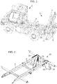
- FIG 1 shows a perspective of a vehicle 2, here a truck ('truck') with a preferred embodiment of a system 1 according to the invention.
- the truck 2 is equipped with a special vehicle frame 3 with a cross-shaped reinforcement 6 so that it can withstand the additional load of an attached working device 7 (here For example, a crane)
- An adapter unit 10 is mounted on the vehicle frame 3 at the rear of the vehicle 2, which can be seen even better in the following figures.
- the adapter unit could also be at the front, but a position at the rear is shown here as this is the most common point of attachment of an implement (Except, for example, from snow plow devices).
- a device carrier 20 is coupled to the adapter unit 10, to which the working device 7 is firmly attached.
- the implement carrier 20 is equipped here with a trailer hitch 4 which is mounted over a bumper 5 which is also attached to the implement carrier 20 .
- This trailer hitch 4 can also be used for coupling and decoupling the device carrier 20 and for its storage, as will be explained in more detail below.
- FIG 2 shows a perspective view of a preferred embodiment of a vehicle frame 3 with a cross-shaped reinforcement 6 with an adapter unit 10 firmly attached to it.
- This adapter unit 10 comprises two adapter plates 16, one adapter plate 16 on the right and one on the left of the central vertical vehicle plane, which are arranged and shaped as mirror images of one another. This then results in two first coupling structures 11, which represent the end pieces of the adapter plates 16 here. These coupling structures 11 are used for coupling to an equipment carrier 20 (see, for example, the following figures).
- figure 3 shows in perspective a preferred embodiment of a device carrier 20.
- a bumper 5 which does not necessarily have to be part of the equipment carrier 20.
- the pulled-down configuration of the equipment carrier 20 where the bumper 5 is fastened is used in some states in particular to meet legal requirements.
- the device carrier 20 is shaped so that it is made with the adapter unit 10 figure 3 can be coupled. To this end, it comprises two second coupling structures 21, which can engage in the first coupling structures 11 of the adapter unit 10, and four locking elements 22 in the form of wedge-shaped bolts, two of which protrude obliquely forwards in the image and two obliquely obliquely backwards.
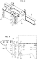
- figure 4 shows a side view of a preferred embodiment of an adapter unit 10 next to a preferred equipment carrier 20, for example an adapter unit 10 figure 2 (Without vehicle frame 3), in addition to a preferred device carrier 20 after figure 3 .
- a dashed box is shown here, which is a working device 7 is intended to symbolize, for example, the foundation of a crane or an earth auger or a power lift.
- the scene shown here could represent the state before the equipment carrier 20 is coupled or after it is uncoupled.
- the device carrier 20 could simply be coupled by sliding it into the adapter unit 10 in the direction of the arrow if the positioning aid 15 were not at the bottom, which would block the pivot pin 24 during this movement.
- Two recesses 14 in the adapter unit can be seen from the side, into which the locking elements 22 (the wedge-shaped retaining bolts) of the device carrier 20 can engage after the device carrier 20 is in a correct coupling position on the adapter unit 10 (see Fig. figure 5 ).
- the first coupling structure 11 of the adapter unit 10 is shaped in such a way that its upper region can at least partially engage in the second coupling structure 21 of the device carrier 20, so that the coupling structures 11, 21 in the coupling position of the adapter unit 10 and device carrier 20 engage in one another in such a way that by a form-fitting first stop 12 and a form-fitting second stop 13 of the coupling structures 11, 21 together, a relative vertical displacement of the equipment carrier 20 to the adapter unit is blocked up and down.
- the first coupling structure 11 has the shape of a bulge in the upper part, which can engage in a matching indentation in the second coupling structure (see the space between the stops 12, 13).
- One of the recesses 14 is arranged in this bulge, so that one of the locking elements 21 of the locking mechanism 22, 23 can engage in the recess 14 of the bulge in the coupling position.
- the adapter unit On its upper side in the rear region, the adapter unit has a bevel 8 which slopes down towards the rear and has an angle of inclination of approximately 45°.
- This bevel is designed in such a way that if the loading area of a vehicle on which it is mounted (see e.g figure 1 ) it does not hit the adapter unit.
- figure 5 shows a preferred way of coupling an adapter unit 10 to a device carrier 20 of a preferred system 1.
- the upper small illustrations show intermediate steps until the coupling position is reached (below).
- Adapter unit 11 moves out so that the pivot pin 24 of the device carrier 20 is located just below the U-shaped positioning aid 15 of the adapter unit 10 .
- the device carrier is lifted slightly upwards in the direction of the lower arrow, so that the pivot pin engages in the positioning aid 15.
- the pivot bolt 24 acts as a physical axis of rotation and guided tilting of the equipment carrier 20 onto the adapter unit 10 is possible (upper curved arrow).
- the device carrier 20 After the device carrier 20 has been tilted onto the adapter unit 10, it is in the coupling position.
- the locking elements 21 of the device carrier 20 can now engage in the recesses 14 of the adapter unit 10 and lock these two elements together in their closed position. Locking under tension, which always presses the equipment carrier 20 against the adapter unit 10, is preferred here.
- the locking elements 22 are preferably wedge-shaped for this purpose, so that the conical bulge of the adapter unit 10 is pressed into the negatively shaped conical bulge of the equipment carrier 20 with continuous outward pressure, so that there is always a firm form-fitting hold. This prevents the adapter unit 10 and the equipment carrier 20 from wobbling relative to one another.
- a decoupling process runs in exactly the opposite direction, that is to say from bottom to top in the figure, in the opposite direction to the arrows.
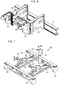
- figure 6 shows a perspective view of a preferred locking of an adapter unit 10 with a preferred device carrier 20 by means of four locking elements 22 which are pressed into their closed position by four movement units 23 (here hydraulic cylinders).
- the device carrier 20 is shown here open at the front, which could be disadvantageous in practice for static reasons.
- FIG 7 shows a preferred embodiment of a storage device 30 in the form of a lift truck 30.
- This storage device 30 includes a receptacle 31 for storing an equipment carrier 20 in the form of a preferred 3-point bracket with three attachment points 31.
- the storage device 30 is shaped here in such a way that it both for storage of an implement carrier 20 with attached implement and for arrangement of the device carrier 20 is designed on an adapter unit 10 of a vehicle 2 . This is explained in more detail below.
- the storage device 30 is designed to be mobile by means of rollers 33, so that it can be moved over a smooth surface and, for example, pushed up to the rear of a truck 2.
- the attachment points 31 of the receptacle 31 can be moved here with regard to their height by means of a lifting device 32 with lifting elements 32 (here hydraulic cylinders), so that they and with them an equipment carrier 20 mounted on them can be raised and lowered vertically (see vertical double arrows).
- lifting elements 32 here hydraulic cylinders
- the two front attachment points 31 can be brought to a different height of the rear attachment point 31 and the receptacle (and thus also an equipment carrier mounted on it) tilted backwards and forwards.
- the rear attachment point 31 is pivotably arranged together with its lifting element 32 (see curved double arrow) so that it can be brought into an attachment position from the side, e.g.
- a secure hold of a device carrier 20 is ensured.
- an equipment carrier 20 can be safely stored with a crane attached to it and pushed into a corner of a warehouse for stowage by means of the storage device 30 .
- the equipment carrier 20 mounted in this way is pushed back onto a truck with the storage device 30 and the equipment carrier 20 is positioned by means of the storage device 30, for example as in FIG figures 4 and 5 shown.
- FIG 8 shows a preferred way of storing an equipment carrier 20 in a preferred storage device 30 in a perspective view.
- the storage device 30 is here the in figure 7 illustrated.
- the status of equipment carrier 20 is mapped to adapter unit 10, as shown in figure 4 is shown.
- the storage device 30 can now be used to move the equipment carrier, as in FIG figure 5 is shown.
- the height of the rear lifting element 32 simply has to be changed, with the two front lifting elements 32 remaining unchanged.
- the rear attachment point 31 engages in a trailer hitch 4 attached to the implement carrier 20 .
- a trailer hitch 4 attached to the implement carrier 20 .
- it serves as a secure and easy-to-use attachment option that can be connected to an attachment point 31 very quickly.
- figure 9 shows a preferred way of storing an equipment carrier 20 in a preferred storage device 30 according to FIG figure 8 in a top view. Here again the attachment of the rear attachment point 31 in the trailer hitch 4 can be seen.
- figure 10 shows a preferred way of storing an equipment carrier 20 in a preferred storage device 30 according to FIG figure 8 in a side view.
- the movements of the device carrier 20 can be understood by moving the lifting elements 32 .
- the curved arrow above the rear lifting element 32 is intended to indicate that this, together with its attachment point 31, can be pivoted in order to easily engage the trailer hitch 4.
- figure 11 shows a side view of a preferred vehicle 2 (here a Unimog) with a system 1 according to the invention, on which a crane 7 is mounted as a working device 7, as is shown in figure 1 is shown, with the difference that a loading area 9 has also been drawn in here.
- the exact structure of the system 1, in particular the construction of the adapter unit 10 attached to the vehicle 2, can be seen here figure 1 remove.
- the loading area 9 can preferably be tilted backwards, as indicated by dashed lines.
- the dashed representation of the loading area shows very well that it can be tilted without any problems despite the attached adapter unit 10 due to the bevel 8 of the adapter unit 10, at least if the crane 7 together with its equipment carrier 20 has been uncoupled, e.g. according to an uncoupling method according to the invention.
Abstract
Die Erfindung betrifft ein System (1) zur Kopplung eines Arbeitsgeräts (7) an einem Fahrzeug (2) das System (1) umfassend eine Adaptereinheit (10), ausgelegt zur festen Anbringung am Heck und/oder an der Front des Fahrzeugs (2) und einen Geräteträger (20) ausgelegt zum Fixieren und Tragen des Arbeitsgeräts (7),- wobei das System (1) so ausgeformt ist, dass der Geräteträger (20) durch Herankippen um eine Drehachse im unteren Bereich der Adaptereinheit (10) und/oder horizontales Einschieben und/oder Einschieben von unten nach oben in eine Koppelposition mit der Adaptereinheit (10) gebracht werden kann und- wobei die Adaptereinheit (10) eine erste Kopplungsstruktur (11) und der Geräteträger (20) eine zweite Kopplungsstruktur (21) aufweisen, wobei diese Kopplungsstrukturen (11, 21) so ausgeformt sind, dass sie in der Koppelposition von Adaptereinheit (10) und Geräteträger (20) dermaßen ineinander greifen, dass durch einen formschlüssigen ersten Anschlag (12) der Kopplungsstrukturen (11, 21) aneinander zumindest eine relative vertikale Verschiebung des Geräteträgers (20) zur Adaptereinheit (10) nach oben blockiert wird und- wobei das System (1) einen Verriegelungsmechanismus (22, 23) mit beweglichen Verriegelungselementen (22) aufweist, welche in eine Schließposition und in eine Entnahmeposition bewegt werden können und in der Schließposition den Geräteträger (20) an der Adaptereinheit (10) fixieren und in der Entnahmeposition von der Adaptereinheit (10) freigeben.Die Erfindung betrifft des Weiteren eine Lagervorrichtung, einen Geräteträger, eine Adaptereinheit, ein Befestigungsverfahren, und ein Trennverfahren.The invention relates to a system (1) for coupling an implement (7) to a vehicle (2), the system (1) comprising an adapter unit (10), designed for fixed attachment to the rear and/or to the front of the vehicle (2) and a device carrier (20) designed for fixing and carrying the working device (7), - the system (1) being shaped in such a way that the device carrier (20) can be tilted about an axis of rotation in the lower area of the adapter unit (10) and/or horizontal sliding and/or sliding from bottom to top can be brought into a coupling position with the adapter unit (10) and- the adapter unit (10) having a first coupling structure (11) and the equipment carrier (20) having a second coupling structure (21), wherein these coupling structures (11, 21) are shaped in such a way that in the coupling position of the adapter unit (10) and equipment carrier (20) they engage in one another in such a way that a form-fitting first stop (12) of the coupling structures (11, 21 ) at least one relative vertical upward displacement of the device carrier (20) to the adapter unit (10) is blocked and- the system (1) having a locking mechanism (22, 23) with movable locking elements (22) which can be moved into a closed position and into can be moved to a removal position and fix the equipment carrier (20) to the adapter unit (10) in the closed position and release it from the adapter unit (10) in the removal position. The invention also relates to a storage device, an equipment carrier, an adapter unit, a fastening method, and a separation process.
Description
Die Erfindung betrifft ein System und ein Verfahren zur Kopplung eines Arbeitsgeräts an einem Fahrzeug, insbesondere an einem Lastkraftwagen ("LKW"). Die Erfindung befasst sich dabei sowohl mit der Ankopplung des Arbeitsgeräts an dem Fahrzeug als auch mit der Abkopplung des Arbeitsgeräts von dem Fahrzeug. Auch das sichere Halten des Arbeitsgeräts am Fahrzeug ist damit gemeint. Insbesondere betrifft die Erfindung eine koppelbare Konsole für Ladekrane oder andere Arbeitsgeräte, die sicher und schnell an- und abgekoppelt werden kann oder Fahrzeuge, die solch eine Koppelmöglichkeit bieten.The invention relates to a system and a method for coupling an implement to a vehicle, in particular to a truck ("truck"). The invention deals both with the coupling of the working device to the vehicle and with the decoupling of the working device from the vehicle. This also means that the implement is held securely on the vehicle. In particular, the invention relates to a dockable console for loading cranes or other work equipment that can be coupled and uncoupled safely and quickly, or vehicles that offer such a coupling option.
Es ist bekannt, Arbeitsgeräte auf Konsolen zu montieren und diese Konsolen an das Heck eines LKW anzubringen. Zur Anbringung ist in der Regel am hinteren Fahrgestellende eine Platte vorgesehen, mit der die Konsole verschraubt oder verbolzt wird. Oftmals wird die Konsole von oben in Halterungen der Platte eingehängt und an der Unterseite mittels bolzen oder Schrauben befestigt.It is known to mount tools on consoles and attach these consoles to the rear of a truck. For attachment, a plate is usually provided at the rear end of the chassis, with which the console is screwed or bolted. The console is often hung from above in brackets on the plate and attached to the underside with bolts or screws.
Das Lösen bzw. Anziehen von Schrauben ist dabei sehr kraft- und zeitaufwendig und bedarf zumindest eines Werkzeugs. Bolzen müssen zwar nicht verschraubt werden, können jedoch verklemmen, zumindest wenn sie Kräfte der Verbindung aufnahmen müssen.The loosening or tightening of screws is very energy-consuming and time-consuming and requires at least one tool. Although bolts do not have to be screwed, they can jam, at least if they have to absorb the forces of the connection.
Was ein Einhängen betrifft, ist dies zuweilen nicht in geschlossenen Hallen möglich, da deren Bauhöhe zu niedrig ist, z.B. ist die Innenraumhöhe von vielen Fahrzeughallen nicht ausreichend, um einen Kran von oben in eine Halterung an einem Fahrzeug einzuhängen.As far as hanging is concerned, this is sometimes not possible in closed halls because their height is too low, e.g. the interior height of many vehicle halls is not sufficient to hang a crane from above in a bracket on a vehicle.
Zudem werden Krane oftmals auf ihren Stützen ggf. mit Zuhilfenahme des Kranarms als dritten Punkt aufgestellt. Dies hat den Nachteil, dass man zur Anbringung mit einem LKW rückwärts an den Kran heranfahren muss, was zum einen großes Geschick erfordert und zum anderen durch das Risiko einer Kollision auch gefährlich für Menschen in der Umgebung sein kann. Zudem kann es passieren, dass ein Kran, der auf seiner eigenen Hydraulik abgestellt wird, durch Temperaturunterschiede und eine damit einhergehende Änderung des Drucks oder Auslenkung der Hydraulik in einen von außen betrachtet undefinierten Zustand geraten kann. Beispielsweise kann er sich neigen oder Druckspannungen in seiner Hydraulik aufbauen. Dies kann zu zusätzlichen Schwierigkeiten oder Gefahren führen.In addition, cranes are often set up on their supports, possibly with the help of the crane arm as a third point. This has the disadvantage that you have to back up to the crane with a truck for attachment, which on the one hand requires great skill and on the other hand can also be dangerous for people in the area due to the risk of a collision. In addition, it can happen that a crane that is parked on its own hydraulic system can get into an undefined state when viewed from the outside due to temperature differences and an associated change in pressure or deflection of the hydraulic system. For example, it can tilt or build up compressive stresses in its hydraulics. This can lead to additional difficulties or dangers.
Letztlich weisen einige Schnellwechselsysteme den Nachteil auf, dass ein angebrachtes Arbeitsgerät mit der Zeit an Spiel gewinnt und dadurch beginnt zu wackeln, was sowohl Nachteilhaft für Arbeiten mit diesem Arbeitsgerät als auch für die Arbeitssicherheit ist.Finally, some quick-change systems have the disadvantage that an attached tool gains play over time and thus begins to wobble, which is disadvantageous both for working with this tool and for work safety.
Es ist eine Aufgabe der vorliegenden Erfindung, Nachteile des Standes der Technik zu überwinden und ein System, Vorrichtungen und Verfahren anzugeben, mit dem eine sichere Kopplung eines Arbeitsgeräts erreicht wird, eine schnelle An- und Abkopplung möglich ist und zudem bevorzugt ein sicherer Halt und insbesondere auch eine vorteilhafte Lagerung gewährleistet wird. Insbesondere ist ein werkzeugfreies An- und Abkoppeln eine Aufgabe dieser Erfindung.It is an object of the present invention to overcome disadvantages of the prior art and to specify a system, devices and methods with which a working device can be coupled securely, quick coupling and decoupling is possible and, moreover, preferably a secure hold and in particular advantageous storage is also ensured. In particular, tool-free coupling and decoupling is an object of this invention.
Diese Aufgabe wird durch ein System gemäß Anspruch 1, eine Lagervorrichtung gemäß Anspruch 8, einen Geräteträger gemäß Anspruch 11, eine Adaptereinheit gemäß Anspruch 12, ein Fahrzeug gemäß Anspruch 13, ein Ankoppelverfahren gemäß Anspruch 14, und ein Abkoppelverfahren gemäß Patentanspruch 15 gelöst.This object is achieved by a system according to
Ein erfindungsgemäßes System dient zur Kopplung eines Arbeitsgeräts an einem (Land-) Fahrzeug, insbesondere einem Lastkraftwagen oder einer selbstfahrenden Geländezugmaschine z.B. einem Traktor oder einem Unimog.A system according to the invention serves to couple an implement to a (land) vehicle, in particular a truck or a self-propelled off-road tractor, e.g. a tractor or a Unimog.
Arbeitsgeräte sind dem Fachmann bekannt und umfassen Grunde alle Arbeitsgeräte, die an einem Fahrzeug angebracht werden können. Die Erfindung ist besonders vorteilhaft für Arbeitsgeräte, die so schwer sind, dass sie ein Mensch sie nicht mehr zu heben vermag. Ein bevorzugtes Arbeitsgerät ist ein Kran, ein Erdbohrer, ein Heckkraftheber. Im Allgemeinen dient die Erfindung dazu, ein System bereitzustellen, dass als universelle Schnittstelle für alle möglichen Arbeitsgeräte zur lösbaren Kopplung an besagtem Fahrzeug dienern kann. Der besondere Vorteil ist, dass ein Fahrzeug nicht fix mit einem Arbeitsgerät ausgestattet sein muss, sondern für mannigfaltige Aufgaben mit und ohne Arbeitsgerät verwendet werden kann und sogar zwischen mehreren Arbeitsgeräten wechseln kann.Tools are known to those skilled in the art and basically include all tools that can be attached to a vehicle. The invention is particularly advantageous for implements that are so heavy that a person can no longer lift them. A preferred implement is a crane, an earth auger, a rear linkage. In general, the invention serves to provide a system that can serve as a universal interface for all possible implements for detachable coupling to said vehicle. The particular advantage is that a vehicle does not have to be permanently equipped with an implement, but can be used for a variety of tasks with and without an implement and can even switch between several implements.
Das System umfasst eine Adaptereinheit (eine "Halterung" am Fahrzeug), ausgelegt zur festen Anbringung am Heck und/oder an der Front des Fahrzeugs und einen Geräteträger ("Konsole" für Arbeitsgeräte) ausgelegt zum Fixieren und Tragen eines Arbeitsgeräts. Zusätzlich umfasst das System noch einen Verriegelungsmechanismus zu einem Verriegeln von Geräteträger und Adaptereinheit. Es ist dabei selbstverständlich, dass der Geräteträger mit Mitteln zum Befestigen eines Arbeitsgeräts ausgestattet sein kann, z.B. mit Löchern, in denen Schrauben das Arbeitsgerät halten können oder Bolzen/Schrauben, auf die das Arbeitsgerät aufgesteckt und daran befestigt werden kann. Jedoch ist auch ein Anschweißen des Arbeitsgeräts auf den Geräteträger möglich. Die Adaptereinheit kann insbesondere Adapterplatte umfassen, welche so angeordnet sind, dass sie vom Fahrzeug fort ragen.The system includes an adapter unit (a "mount" on the vehicle) designed for fixed attachment to the rear and/or front of the vehicle and an implement carrier ("tool bracket") designed to fix and support an implement. In addition, the system also includes a locking mechanism for locking the equipment carrier and adapter unit. It goes without saying that the Device carrier can be equipped with means for attaching a tool, for example with holes in which screws can hold the tool or bolts / screws on which the tool can be plugged and attached to it. However, it is also possible to weld the implement onto the implement carrier. The adapter unit can in particular include adapter plates which are arranged in such a way that they protrude away from the vehicle.
Das System ist dabei so ausgeformt, dass der Geräteträger durch Herankippen um eine Drehachse im unteren Bereich der Adaptereinheit und/oder durch horizontales Einschieben und/oder Einschieben von unten nach oben in eine Koppelposition mit der Adaptereinheit gebracht werden kann. Es findet also insbesondere kein Einhängen von oben statt, was bei hohen Arbeitsgeräten wie z.B. Kränen in einer niedrigen Halle problematisch ist. Die Drehachse muss nicht unbedingt eine physische Achse sein, sondern kann auch eine theoretische Linie sein, um die herum gedreht wird. Das Einschieben von unten nach oben ist besonders vorteilhaft als Vorbereitung für ein Herankippen des Geräteträgers. Ein verkippter Geräteträger kann zunächst mit einer Ausformung (z.B. einem Drehbolzen) im unteren Bereich von unten nach oben in eine Positionierungshilfe im unteren Bereich der Adaptereinheit eingeschoben werden, was eine horizontale Positionierung sehr erleichtert. Daraufhin kann der Geräteträger um die Drehachse in der Positionierungshilfe herum an die Adaptereinheit herangekippt werden.The system is designed in such a way that the equipment carrier can be brought into a coupling position with the adapter unit by tilting it around a pivot axis in the lower area of the adapter unit and/or by sliding it in horizontally and/or from bottom to top. In particular, there is no hanging from above, which is problematic with high work equipment such as cranes in a low hall. The axis of rotation does not necessarily have to be a physical axis, but can also be a theoretical line to rotate around. Sliding in from the bottom up is particularly advantageous in preparation for tipping the equipment carrier. A tilted device carrier can first be pushed into a positioning aid in the lower area of the adapter unit with a protrusion (e.g. a pivot bolt) in the lower area from bottom to top, which makes horizontal positioning much easier. The equipment carrier can then be tilted towards the adapter unit around the axis of rotation in the positioning aid.
Des Weiteren weist die Adaptereinheit eine erste Kopplungsstruktur und der Geräteträger eine zweite Kopplungsstruktur auf, wobei diese Kopplungsstrukturen so ausgeformt sind, dass sie in der Koppelposition von Adaptereinheit und Geräteträger dermaßen ineinandergreifen, dass durch einen formschlüssigen ersten Anschlag der Kopplungsstrukturen aneinander zumindest eine relative vertikale Verschiebung des Geräteträgers zur Adaptereinheit nach oben blockiert wird. Mit "Anschlag" ist hier eine Ausformung gemeint, mit der der Geräteträger in der Koppelposition von unten an eine Struktur der Adaptereinheit anstößt, so dass über diesen Anstoß hinaus keine weitere Bewegung des Geräteträgers relativ zur Adaptereinheit in der Koppelposition möglich ist. Der Geräteträger muss also mit einem Element unter eine Struktur der Adaptereinheit "untergeschoben" werden.Furthermore, the adapter unit has a first coupling structure and the device carrier has a second coupling structure, these coupling structures being shaped in such a way that they engage in one another in the coupling position of the adapter unit and device carrier such that a positive first stop of the coupling structures against one another causes at least a relative vertical displacement of the Device carrier to the adapter unit is blocked upwards. "Stop" here means a shape with which the device carrier in the coupled position hits a structure of the adapter unit from below, so that beyond this impact no further movement of the device carrier relative to the adapter unit in the coupled position is possible. The equipment carrier must therefore be "slide under" with an element under a structure of the adapter unit.
Beispielsweise weist der Geräteträger eine vorspringende Struktur auf die in der Koppelposition von unten gegen eine Einbuchtung der Adaptereinheit stößt, oder die Adaptereinheit weist einen Vorsprung auf, gegen den der untere Rand einer Einbuchtung des Geräteträgers stößt. Dieser Anschlag liegt bevorzugt in einem oberen Bereich des Geräteträgers (oberhalb der Mitte), während eine Drehachse zum Herankippen bevorzugt im unteren Bereich (unterhalb der Mitte) des Geräteträgers liegt.For example, the equipment carrier has a protruding structure which, in the coupled position, abuts against an indentation in the adapter unit from below, or the adapter unit has a protrusion against which the lower edge of an indentation in the equipment carrier abuts. This stop is preferably in an upper area of the Device carrier (above the center), while a pivot axis for tilting is preferred in the lower area (below the center) of the device carrier.
Es wird darauf hingewiesen, dass der Geräteträger in der Koppelposition in der Regel nach vorne oder nach hinten aus dem Fahrzeug herausragt. Es ist daher bevorzugt, den Geräteträger mit einer Stoßstange und/oder Beleuchtungselementen auszustatten und/oder ggf. einer Anhängerkupplung. Eine elektrische Verbindung für Beleuchtungselemente kann mittels einer Steckverbindung auf einfache Weise erreicht werden.It is pointed out that the equipment carrier in the coupled position usually protrudes forwards or backwards out of the vehicle. It is therefore preferred to equip the device carrier with a bumper and/or lighting elements and/or possibly a trailer hitch. An electrical connection for lighting elements can be achieved in a simple manner by means of a plug connection.
Die Kopplungsstrukturen können separate Strukturen sein, die an die Adaptereinheit bzw. den Geräteträger fest angebracht worden sind, z.B. geschraubt oder geschweißt. Sie können aber auch Ausformungen von Bereichen der Adaptereinheit bzw. des Geräteträgers sein, die der jeweils anderen Kopplungsstruktur zugewandt sind. Beispielsweise sind die Enden von Adapterplatte der Adaptereinheit als Kopplungsstrukturen ausgeformt.The coupling structures can be separate structures that have been permanently attached, e.g. screwed or welded, to the adapter unit or the equipment carrier. However, they can also be formations of areas of the adapter unit or of the equipment carrier which face the respective other coupling structure. For example, the ends of the adapter plate of the adapter unit are formed as coupling structures.
Besagter Verriegelungsmechanismus umfasst bewegliche Verriegelungselemente, z.B. Verriegelungsbolzen, welche in eine Schließposition und in eine Entnahmeposition bewegt werden können und in der Schließposition den Geräteträger an der Adaptereinheit fixieren und in der Entnahmeposition von der Adaptereinheit freigeben. Die Bewegung der Verriegelungselemente ist bevorzugt eine laterale Verschiebung, kann jedoch auch je nach Form der Verriegelungselemente eine Drehung beinhalten. Beispielsweise werden Verriegelungsbolzen mittels Hydraulikzylindern verschoben. In der Schließposition greifen die Verriegelungselemente dermaßen in Adaptereinheit und Geräteträger ein (z.B. in Löcher), dass diese aneinander fixiert und bevorzugt auch miteinander verspannt werden. In der Entnahmeposition ist diese Fixierung gelöst, so dass Adaptereinheit und Geräteträger voneinander getrennt werden können. Es ist bevorzugt, dass der Verriegelungsmechanismus vom Fahrzeug aus mit Energie versorgt wird, z.B. mit Strom oder Öldruck für eine Hydraulik. Dabei ist insbesondere bevorzugt, dass eine Verbindung von dem Geräteträger zum Fahrzeug mittels Steckverbindungen schnell getrennt bzw. verbunden werden kann.Said locking mechanism comprises movable locking elements, e.g. locking bolts, which can be moved into a closed position and into a removal position and fix the device carrier to the adapter unit in the closed position and release it from the adapter unit in the removal position. The movement of the locking elements is preferably lateral displacement, but can also include rotation depending on the shape of the locking elements. For example, locking bolts are moved using hydraulic cylinders. In the closed position, the locking elements engage in the adapter unit and equipment carrier (e.g. in holes) in such a way that they are fixed to one another and preferably also clamped together. This fixation is released in the removal position, so that the adapter unit and equipment carrier can be separated from one another. It is preferred that the locking mechanism be powered from the vehicle, e.g., power or oil pressure for a hydraulic system. It is particularly preferred that a connection from the device carrier to the vehicle can be quickly disconnected or connected by means of plug connections.
Zusammen mit dem formschlüssigen Anschlag von unten hat eine solche Verriegelung den Vorteil, dass Kräfte des Arbeitsgeräts gut aufgefangen und in einen Fahrzeugrahmen geleitet werden können.Together with the form-fitting stop from below, such a locking has the advantage that forces from the implement can be absorbed well and directed into a vehicle frame.
Es wird darauf hingewiesen, dass bei der Erfindung die Verriegelungselemente nicht die gesamte Last der Kopplung aufnehmen, sondern durch die formschlüssigen Anschläge ebenfalls Last aufgenommen wird. Die Bolzen pressen die Adaptereinheit und den Geräteträger an deren Kopplungsstrukturen aneinander, wodurch die entstehenden Kräfte auf beide Komponenten Verriegelungselemente und Kopplungsstrukturen aufgeteilt werden. Reine Zugkräfte nach hinten, z.B. wenn eine Anhängerkupplung an den Geräteträger angebracht und ein Anhänger angehängt ist, könnten jedoch komplett von den Verriegelungselementen aufgenommen werden, zumindest wenn der Geräteträger zur Kopplung nur horizontal herangeschoben werden musste.It is pointed out that in the case of the invention, the locking elements do not absorb the entire load of the coupling, but the load is also absorbed by the form-fitting stops. The bolts press the adapter unit and the device carrier together at their coupling structures, as a result of which the resulting forces are divided between the two components, locking elements and coupling structures. However, pure pulling forces to the rear, e.g. when a trailer hitch is attached to the implement carrier and a trailer is attached, could be completely absorbed by the locking elements, at least if the implement carrier only had to be pushed horizontally for coupling.
Es wird darauf hingewiesen, dass Bezeichnungen wie "hinten" oder "vorne" sich jeweils auf die bestimmungsgemäße Kopplung am Fahrzeug beziehen. Mit "Hinten" ist stets die fahrzeugabgewandte Seite und mit "vorne" die fahrzeugzugewandte Seite gemeint. Bei einer Verkippung ist die Oberseite des verkippten Elements relevant. eine Verkippung "nach hinten" bedeutet, dass die Oberseite nach hinten verkippt ist. Bei einer Verkippung "nach vorne" bewegt sich die Oberseite auf das Fahrzeug zu. Bei einer Kopplung am Heck eines Fahrzeugs kann das Koordinatensystem des Fahrzeugs bezüglich "hinten" und "vorne" verwendet werden. Bei einer Anbringung an der Front ist es genau umgekehrt.It is pointed out that designations such as "rear" or "front" refer to the intended coupling on the vehicle. “Rear” always means the side facing away from the vehicle and “front” means the side facing the vehicle. In the case of a tilt, the top of the tilted element is relevant. a tilt "backwards" means that the top is tilted backwards. With a "forward" tilt, the top moves towards the vehicle. In the case of a coupling at the rear of a vehicle, the vehicle's coordinate system in terms of "rear" and "front" can be used. When attached to the front, it is exactly the opposite.
Das erfindungsgemäße System ist sehr vorteilhaft mit einer besonderen Lagervorrichtung einsetzbar, die eine besonders einfache Kopplung und zudem ein Lagern des Arbeitsgerätes erlaubt. Eine solche Lagervorrichtung könnte auch eine eigenständige Erfindung darstellen, wobei sich jedoch bestimmte Vorteile erst in Kombination mit dem erfindungsgemäßen System zeigen.The system according to the invention can be used very advantageously with a special storage device that allows a particularly simple coupling and also storage of the working device. Such a storage device could also represent an independent invention, although certain advantages only become apparent in combination with the system according to the invention.
Eine erfindungsgemäße Lagervorrichtung umfasst eine Aufnahme zur Lagerung eines Geräteträgers, wobei die Lagervorrichtung, wie gesagt, insbesondere zur Verwendung in einem System nach einem der vorangehenden Ansprüche ausgelegt ist. Die Lagervorrichtung ist dabei zur Lagerung des Geräteträgers ausgelegt und/oder zur Anordnung des Geräteträgers an einer Adaptereinheit eines Fahrzeugs ausgelegt. Zu diesem Zweck ist die Lagervorrichtung dazu ausgestaltet, den Geräteträger zusammen mit einem an diesem befestigen Arbeitsgerät lösbar fixiert an der Aufnahme zu halten, und bevorzugt die Aufnahme bezüglich ihrer Höhe und/oder Neigung zu bewegen.A storage device according to the invention comprises a receptacle for storing an equipment carrier, the storage device, as stated, being designed in particular for use in a system according to one of the preceding claims. The bearing device is designed for mounting the equipment carrier and/or for arranging the equipment carrier on an adapter unit of a vehicle. For this purpose, the storage device is designed to hold the device carrier together with a working device attached to it in a detachably fixed manner on the receptacle, and preferably to move the receptacle with respect to its height and/or inclination.
Bevorzugt umfasst die Lagervorrichtung Rollen zum Bewegen der Lagervorrichtung über eine Bodenfläche. Dies ist besonders vorteilhaft, da eine solche Lagervorrichtung zum Ankoppeln eins Arbeitsgerätes in eine passende Position an einem Fahrzeug geschoben werden kann bzw. nach dem Abkoppeln das Arbeitsgerät einfach an einen Ort zur Lagerung verschoben werden kann. Bevorzugt sind dabei mindestens zwei der Rollen lenkbar gestaltet.Preferably, the storage device comprises rollers for moving the storage device over a floor surface. This is particularly advantageous since such a storage device can be slid into a suitable position on a vehicle for coupling an implement or, after uncoupling, the implement can simply be moved to a place for storage. At least two of the rollers are preferably designed to be steerable.
Auch wenn ein Geräteträger Teil des Systems ist, kann es dennoch von Vorteil sein, ihn als Einzelstück anzusehen, z.B. in dem Fall, dass zwischen mehreren Arbeitsgeräten gewechselt werden soll. Jedes Arbeitsgerät kann an einem eigenen Geräteträger angebracht sein, und insbesondere auf einer eigenen Lagervorrichtung gelagert sein.Even if an implement carrier is part of the system, it can still be advantageous to consider it as a single piece, e.g. in the case of switching between several implements. Each working device can be attached to its own device carrier and, in particular, can be stored on its own storage device.
Ein erfindungsgemäßer Geräteträger ist zur Verwendung in einem erfindungsgemäßen System ausgelegt. Er umfasst bevorzugt ein Halterungselement an seiner Unterseite, das so angebracht und geformt ist, dass es mit einer Aufnahme einer erfindungsgemäßen Lagervorrichtung lösbar verbunden werden kann. Des Weiteren ist bevorzugt, dass der Geräteträger einen Drehbolzen aufweist, der als eine physische Drehachse zum Herankippen des Geräteträgers an eine Adaptereinheit (in eine Koppelposition) dienen kann und insbesondere als Halterungselement verwendet werden kann. In dieser Beschreibung genannte Merkmale des Systems, die sich auf dessen Geräteträger beziehen, beziehen sich ebenfalls auf diesen erfindungsgemäßen Geräteträger.A device carrier according to the invention is designed for use in a system according to the invention. It preferably comprises a holding element on its underside, which is attached and shaped in such a way that it can be releasably connected to a receptacle of a storage device according to the invention. Furthermore, it is preferred that the device carrier has a pivot pin, which can serve as a physical axis of rotation for tilting the device carrier onto an adapter unit (into a coupling position) and can be used in particular as a holding element. Features of the system mentioned in this description, which relate to its equipment carrier, also relate to this equipment carrier according to the invention.
Genauso kann es von Vorteil sein, eine Adaptereinheit als Einzelstück anzusehen, z.B. wenn ein Arbeitsgerät von mehreren Fahrzeugen verwendet werden soll. An jedem Fahrzeug kann dessen eigene (bezüglich relevanter Bereiche identisch geformte) Adaptereinheit angebracht sein, die mit einem Geräteträger oder mehreren Geräteträgern mit unterschiedlichen Arbeitsgeräten verbunden werden kann.It can also be an advantage to consider an adapter unit as a single piece, e.g. if one tool is to be used by several vehicles. Each vehicle can have its own adapter unit (identically shaped with regard to relevant areas) attached, which can be connected to an implement carrier or multiple implement carriers with different implements.
Eine erfindungsgemäße Adaptereinheit ist zur Verwendung in einem erfindungsgemäßen System ausgelegt. Die Adaptereinheit ist bevorzugt an einem Fahrzeugrahmen angebracht, welcher mit einer, insbesondere kreuzförmigen, Versteifung gegen Scherkräfte und/oder Torsionskräfte versehen ist. In dieser Beschreibung genannte Merkmale des Systems, die sich auf dessen Adaptereinheit beziehen, beziehen sich ebenfalls auf diese erfindungsgemäße Adaptereinheit.An adapter unit according to the invention is designed for use in a system according to the invention. The adapter unit is preferably attached to a vehicle frame which is provided with a reinforcement, in particular a cross-shaped reinforcement, against shearing forces and/or torsional forces. Features of the system mentioned in this description, which relate to its adapter unit, also relate to this adapter unit according to the invention.
Ein erfindungsgemäßes Fahrtzeug ist insbesondere ein Lastkraftwagen bzw. ein Unimog und umfasst eine erfindungsgemäße Adaptereinheit, die an dem Fahrzeug fest montiert ist. Bevorzugt weist das Fahrzeug zusätzlich einen Fahrzeugrahmen auf, mit einer Versteifung wie sie im Folgenden noch genauen beschrieben wird.A vehicle according to the invention is in particular a truck or a Unimog and includes an adapter unit according to the invention which is permanently mounted on the vehicle. The vehicle preferably also has a vehicle frame with a stiffener, as will be described in more detail below.
Ein erfindungsgemäßes Ankoppelverfahren zum Ankoppeln eines Geräteträgers eines erfindungsgemäßen Systems (bzw. eines erfindungsgemäßen Geräteträgers) an einem Fahrzeug umfasst die folgenden Schritte:
- Bereitstellen eines Fahrzeugs mit einer daran montierten Adaptereinheit eines erfindungsgemäßen Systems nach einem der vorangehenden Ansprüche,
- Positionieren des Geräteträgers im Bereich der Adaptereinheit, insbesondere mittels einer beweglichen Lagervorrichtung gemäß der Erfindung, wobei bevorzugt die Höhe des Geräteträgers mittels einer Hubeinrichtung der Lagervorrichtung eingestellt wird,
- Herankippen des Geräteträgers um eine Drehachse im unteren Bereich der Adaptereinheit und/oder horizontales Einschieben des Geräteträgers in eine Koppelposition mit der Adaptereinheit,
- Fixieren des Geräteträgers mittels des Verriegelungsmechanismus, wobei mindestens ein Verriegelungselement in eine Schließposition bewegt wird.
- Providing a vehicle with an adapter unit mounted thereon of a system according to the invention according to one of the preceding claims,
- Positioning the equipment carrier in the area of the adapter unit, in particular by means of a movable storage device according to the invention, with the height of the equipment carrier preferably being adjusted by means of a lifting device of the storage device,
- Tilting the equipment carrier around a pivot in the lower area of the adapter unit and/or horizontally sliding the equipment carrier into a coupling position with the adapter unit,
- Fixing the device carrier by means of the locking mechanism, with at least one locking element being moved into a closed position.
Ein erfindungsgemäßes Abkoppelverfahren zum Abkoppeln eines Geräteträgers eines erfindungsgemäßen Systems (bzw. eines erfindungsgemäßen Geräteträgers) von einem Fahrzeug, umfasst die folgenden Schritte:
- Positionieren einer Lagervorrichtung, bevorzugt erfindungsgemäße Lagervorrichtung, insbesondere eines Hubwagens, unter dem Geräteträger,
- Freigeben des Geräteträgers mittels des Verriegelungsmechanismus, wobei mindestens ein Verriegelungselement in eine Entnahmeposition bewegt wird,
- Auskippen des Geräteträgers um eine Drehachse im unteren Bereich der Adaptereinheit und oder horizontales Herausschieben des Geräteträgers aus einer Koppelposition mit der Adaptereinheit, bevorzugt mittels einer Hubeinrichtung der Lagervorrichtung.
- Positioning a storage device, preferably a storage device according to the invention, in particular a lift truck, under the equipment carrier,
- Releasing the device carrier by means of the locking mechanism, with at least one locking element being moved into a removal position,
- Tilting out the device carrier about an axis of rotation in the lower area of the adapter unit and/or horizontally pushing out the device carrier from a coupling position with the adapter unit, preferably by means of a lifting device of the storage device.
Weitere besonders vorteilhafte Ausgestaltungen und Weiterbildungen der Erfindung ergeben sich aus den abhängigen Ansprüchen sowie der nachfolgenden Beschreibung, wobei die Patentansprüche einer bestimmten Kategorie auch gemäß den abhängigen Ansprüchen einer anderen Kategorie weitergebildet sein können und Merkmale verschiedener Ausführungsbeispiele zu neuen Ausführungsbeispielen kombiniert werden können. Gemäß einer bevorzugten Ausführungsform greifen die Kopplungsstrukturen in der Koppelposition von Adaptereinheit und Geräteträger zusätzlich so ineinander, dass in der Koppelposition durch einen formschlüssigen zweiten Anschlag der Kopplungsstrukturen aneinander eine relative vertikale Verschiebung des Geräteträgers zur Adaptereinheit nach unten blockiert wird. Es ist also nun ein vertikales Verschieben von Adaptereinheit und Geräteträger zueinander in der Koppelposition nicht mehr möglich (weder nach oben noch nach unten). Dies erhöht die Qualität der Halterung eines Arbeitsgerätes, da dieses ohne zu wackeln gehalten werden kann und Kräfte sicher in die Fahrzeugstruktur einen Fahrzeugrahmen) eingeleitet werden können. Bevorzugt sind die Kopplungsstrukturen so geformt, dass eine der Kopplungsstrukturen (z.B. die erste Kopplungsstruktur an der Adaptereinheit) eine Ausbuchtung aufweist, die in eine passende Einbuchtung der anderen Kopplungsstruktur (z.B. der zweiten Kopplungsstruktur an dem Geräteträger) eingreifen kann, so dass auf diese Weise in der Koppelposition die beiden formschlüssigen Anschläge der Kopplungsstrukturen aneinander hergestellt werden.Further particularly advantageous configurations and developments of the invention result from the dependent claims and the following description, whereby the patent claims of a specific category can also be developed according to the dependent claims of another category and features of different exemplary embodiments can be combined to form new exemplary embodiments. According to a preferred embodiment, the coupling structures in the coupling position of the adapter unit and device carrier also interlock so that in the coupling position a positive second stop of the coupling structures on one another blocks a relative vertical displacement of the device carrier to the adapter unit downwards. It is now no longer possible to move the adapter unit and device carrier vertically in relation to one another in the coupled position (neither up nor down). This increases the quality of the attachment of an implement, since it can be held without wobbling and forces can be introduced safely into the vehicle structure (a vehicle frame). The coupling structures are preferably shaped in such a way that one of the coupling structures (e.g. the first coupling structure on the adapter unit) has a bulge which can engage in a matching indentation in the other coupling structure (e.g. the second coupling structure on the equipment carrier), so that in this way the coupling position, the two form-fitting stops of the coupling structures are produced on one another.
Es ist dabei anzumerken, dass sich Konsolen über die Zeit mitunter gelockert haben, so dass sie mit dem Arbeitsgerät an ihrer Halteplatte wackelten, z.B. durch Abschliff von Material. Es ist diesbezüglich bevorzugt, dass der erste Anschlag sowie der zweite Anschlag mittels konischen bzw. keilförmigen Strukturen gebildet werden, z.B. einer keilförmigen Ausbuchtung, die in eine entsprechend keilförmige Einbuchtung eingreift. Zudem ist bevorzugt, dass eine Verriegelung mittels der Verriegelungselementen so gestaltet ist, dass sie in Schließposition stets eine Spannung auf den Formschluss der Anschläge ausübt. Dies kann z.B. durch keilförmige Verriegelungselemente erreicht werden, die so in Ausnehmungen eingreifen, dass eine resultierende Kraft auf die Anschläge wirkt. Eine Spannung kann durch Druck in Hydraulikzylindern erreicht werden oder durch eine gefederte Halterung der Verriegelungselemente, z.B. durch eine Feder. Es ist dabei besonders bevorzugt, dass ein Verriegelungselement, z.B. ein Verriegelungsbolzen des Verriegelungsmechanismus in der Koppelposition in einem Bereich zwischen dem ersten Anschlag und den zweiten Anschlag blockierend eingreift, insbesondere in eine Ausnehmung in der Ausbuchtung.It should be noted that brackets have sometimes become loose over time, so that they wobbled with the work tool on their mounting plate, e.g. due to abrasion of material. It is preferred in this respect that the first stop and the second stop are formed by means of conical or wedge-shaped structures, e.g. a wedge-shaped bulge which engages in a correspondingly wedge-shaped indentation. In addition, it is preferred that locking by means of the locking elements is designed in such a way that in the closed position it always exerts a tension on the positive locking of the stops. This can be achieved, for example, with wedge-shaped locking elements that engage in recesses in such a way that a resultant force acts on the stops. Tension can be achieved by pressure in hydraulic cylinders or by spring-loaded mounting of the locking elements, e.g. by a spring. It is particularly preferred that a locking element, e.g. a locking bolt of the locking mechanism, engages in a blocking manner in the coupling position in a region between the first stop and the second stop, in particular in a recess in the bulge.
Gemäß einer bevorzugten Ausführungsform weist die Adaptereinheit zwei erste Kopplungsstrukturen auf, die rechts und links zu einer mittleren vertikalen Fahrzeugebene, insbesondere spiegelbildlich zu dieser, angeordnet sind und bevorzugt gleichartig geformt sind. Dies kann z.B. durch jeweils eine Adapterplatte rechts und eine links zur Fahrzeugmitte erreicht werden. Eine solche Ausführungsform hat den Vorteil, dass Kräfte, die ein Arbeitsgerät über den Geräteträger auf die Adaptereinheit ausübt, symmetrisch in die Fahrzeugkonstruktion eingeleitet werden können und insbesondere Torsionskräften ein wirksamer Hebel entgegengebracht wird. Bei einer solchen Ausführungsform sollte natürlich auch der Geräteträger zwei, bevorzugt parallel formschlüssig wirkende, zweite Kopplungsstrukturen aufweisen, die so geformt und angeordnet sind, dass sie in der Koppelposition in die beiden ersten Kopplungsstrukturen eingreifen.According to a preferred embodiment, the adapter unit has two first coupling structures, which are arranged to the right and left of a middle vertical vehicle plane, in particular mirror-inverted to this, and are preferably shaped in the same way. This can be achieved, for example, with an adapter plate on the right and one on the left towards the center of the vehicle. Such an embodiment has the advantage that forces a Working device exerts on the device carrier on the adapter unit, can be introduced symmetrically into the vehicle construction and in particular torsional forces are countered with an effective lever. In such an embodiment, of course, the equipment carrier should also have two second coupling structures, preferably acting in parallel with a positive fit, which are shaped and arranged such that they engage in the two first coupling structures in the coupling position.
Gemäß einer bevorzugten Ausführungsform ist die Adaptereinheit an einem Fahrzeugrahmen angebracht, welcher mit einer, insbesondere kreuzförmigen, Versteifung gegen Scherkräfte und/oder Torsionskräfte versehen ist. Auf diese Weise können Kräfte gut in den Fahrzeugrahmen eingebracht werden, der diese durch die bevorzugte Versteifung ohne eine gravierende Verformung aufnehmen kann. Durch die Versteifung kann sich auch der Vorteil ergeben, dass der Fahrzeugrahmen niedriger gebaut werden kann, als ein herkömmlicher Fahrzeugrahmen, was vorteilhaft in einer geringeren Höhe einer Ladefläche resultieren kann.According to a preferred embodiment, the adapter unit is attached to a vehicle frame, which is provided with a reinforcement, in particular a cross-shaped reinforcement, against shearing forces and/or torsional forces. In this way, forces can be well introduced into the vehicle frame, which can absorb them without serious deformation due to the preferred stiffening. The stiffening can also result in the advantage that the vehicle frame can be built lower than a conventional vehicle frame, which can advantageously result in a lower height of a loading area.
Gemäß einer bevorzugten Ausführungsform umfasst der Verriegelungsmechanismus eine Bewegungseinheit zur automatischen Bewegung der Verriegelungselemente in die Schließposition und die Entnahmeposition. Diese Bewegungseinheit kann mannigfaltiger Natur sein, z.B. ein Linearmotor oder ein Zylinder, z.B. einer Pneumatik oder Hydraulik, wobei eine Hydraulik bzw. eine Gruppe hydraulischer Zylinder bevorzugt ist. Die Bewegungseinheit ist bevorzugt an dem Geräteträger angeordnet und die Verriegelungselemente greifen in der Schließposition in Löcher in der Adaptereinheit ein. Alternativ ist die Bewegungseinheit bevorzugt an der Adaptereinheit angeordnet und die Verriegelungselemente greifen in der Schließposition in Löcher in dem Geräteträger ein. Die Löcher befinden sich dabei insbesondere in einer Kopplungsstruktur.According to a preferred embodiment, the locking mechanism comprises a movement unit for automatically moving the locking elements into the closed position and the removal position. This movement unit can be of various nature, e.g. a linear motor or a cylinder, e.g. a pneumatic or hydraulic system, whereby a hydraulic system or a group of hydraulic cylinders is preferred. The movement unit is preferably arranged on the device carrier and the locking elements engage in holes in the adapter unit in the closed position. Alternatively, the movement unit is preferably arranged on the adapter unit and the locking elements engage in holes in the equipment carrier in the closed position. The holes are located in particular in a coupling structure.
Generell sei hier gesagt, dass jegliche Bewegung von Elementen z.B. zur Justage oder Verriegelung mittels einer Motorisierung (z.B. eine motorisierte Hydraulikpumpe) oder durch Handbetrieb (z.B. eine Handpumpe für eine Hydraulik) erfolgen kann. Bevorzugt werden diesbezügliche Komponenten, die mit dem Fahrzeug verbunden sind (z.B. die Adaptereinheit) oder mit diesem verbindbar sind (z.B. der Geräteträger) durch eine Motorisierung betrieben, bevorzugt durch eine Hydraulikpumpe des Fahrzeugs. Der Geräteträger ist dazu bevorzugt mittels einer Schnellkupplung für eine Hydraulik und/oder eine Elektrik mit dem Fahrzeug verbunden. Bewegungen bei Komponenten, die nicht mit dem Fahrzeug verbunden werden sollen, z.B. ein Hubwagen wie unten beschrieben, werden bevorzugt mit einer eigenen Motorisierung oder mittels Handbetrieb erreicht.In general, it should be said here that any movement of elements, for example for adjustment or locking, can take place by means of a motor (eg a motorized hydraulic pump) or by manual operation (eg a hand pump for a hydraulic system). Components in this regard that are connected to the vehicle (eg the adapter unit) or can be connected to it (eg the equipment carrier) are preferably operated by a motor, preferably by a hydraulic pump of the vehicle. For this purpose, the implement carrier is preferably connected to the vehicle by means of a quick coupling for hydraulic and/or electric systems. Movements in components not involving are to be connected to the vehicle, eg a lift truck as described below, are preferably achieved with their own motorization or by means of manual operation.
Für eine vorteilhafte Verriegelung greifen in eine Kopplungsstruktur in der Schließposition zwei Verriegelungselemente (Verriegelungsbolzen) ein. Bezüglich der oben beschriebenen bevorzugten Ausführungsform, bei der sich eine Adapterplatte rechts und eine links der Fahrzeugmitte befindet, wären die zwei Verriegelungselemente rechts und zwei links. Bevorzugt greift dabei ein Verriegelungselement im oberen Bereich der Kopplungsstruktur ein und eines im unteren Bereich, was eine optimale Lastverteilung ergibt.For advantageous locking, two locking elements (locking bolts) engage in a coupling structure in the closed position. Regarding the preferred embodiment described above, where one adapter plate is on the right and one on the left of the center of the vehicle, the two locking elements would be on the right and two on the left. One locking element preferably engages in the upper area of the coupling structure and one in the lower area, which results in an optimal load distribution.
Wie oben bereits gesagt, sind die Verriegelungselemente bevorzugt keilförmig gestaltet, so dass bei einem kontinuierlichen Druck auf den Bereich der Verriegelung eine konische Ausbuchtung (z.B. der Adaptereinheit) in eine negativ geformte konische Einbuchtung (z.B. des Geräteträgers) gepresst wird, so dass stets ein fester formschlüssiger Halt vorliegt. Dadurch wird ein Wackeln von Adaptereinheit und Geräteträger zueinander durch formschlüssige Anschläge verhindert.As already mentioned above, the locking elements are preferably wedge-shaped, so that with continuous pressure on the locking area, a conical bulge (e.g. of the adapter unit) is pressed into a negatively shaped conical indentation (e.g. of the equipment carrier), so that a firm there is a form-fitting hold. This prevents the adapter unit and device carrier from wobbling in relation to one another by means of form-fitting stops.
Gemäß einer bevorzugten Ausführungsform weist mindestens eine erste Kopplungsstruktur der Adaptereinheit an ihrer Unterseite eine nach unten offene Positionierungshilfe auf, insbesondere eine U-förmige Aussparung. Der Geräteträger weist in diesem Falle bevorzugt einen Drehbolzen auf, der so angeordnet ist, dass er zum Erreichen der Koppelposition von unten in die Positionierungshilfe hinein bewegt werden muss. Damit ist zwar kein rein horizontales Einschieben mehr möglich, jedoch kann ein Herankippen einfach über diese Drehbolzen als Drehachse erfolgen. Der in die Positionierungshilfe eingeschobene Drehbolzen bildet also in diesem Falle eine physische Drehachse zum Herankippen des Geräteträgers. Diesbezüglich wird beim Ankoppeln bevorzugt ein leicht nach hinten gekippter und (bezüglich der Höhe der Koppelposition) leicht abgesenkter Geräteträger zunächst horizontal an die Adapterplatte herangeschoben, dann nach oben gehoben bis die Drehbolzen in die Positionierungshilfe eingreifen und anschließend nach vorne an die Adaptereinheit herangekippt.According to a preferred embodiment, at least one first coupling structure of the adapter unit has on its underside a positioning aid open at the bottom, in particular a U-shaped recess. In this case, the device carrier preferably has a pivot bolt which is arranged in such a way that it has to be moved from below into the positioning aid in order to reach the coupling position. Although this means that it is no longer possible to slide it in purely horizontally, it can be tilted up simply using these pivot pins as the axis of rotation. In this case, the pivot bolt pushed into the positioning aid forms a physical axis of rotation for tilting the device carrier. In this regard, when coupling, a device carrier that is tilted slightly backwards and (relative to the height of the coupling position) slightly lowered is first pushed horizontally towards the adapter plate, then lifted upwards until the pivot bolts engage in the positioning aid and then tilted forwards towards the adapter unit.
Gemäß einer bevorzugten Ausführungsform weist mindestens eine zweite Kopplungsstruktur an dem Geräteträger an ihrer Unterseite ein Halterungselement auf, das bevorzugt mit einer Aufnahme einer erfindungsgemäßen Lagervorrichtung lösbar verbunden werden kann (also z.B. für eine sichere Halterung an einem Hubwagen benötigt wird). Dieses Halterungselement ist bevorzugt ein vorgenannter Drehbolzen (der länger gestaltet ist, als zum Drehen unbedingt notwendig) oder eine Verlängerung eines Drehbolzens. In einen solchen Bolzen können Haken an einer Lagervorrichtung sehr gut eingreifen und einen sicheren Halt gewährleisten.According to a preferred embodiment, at least a second coupling structure on the equipment carrier has a mounting element on its underside, which can preferably be detachably connected to a receptacle of a storage device according to the invention (ie required for secure mounting on a lift truck, for example). This mounting element is preferably an aforesaid pivot pin (the designed longer than absolutely necessary for turning) or an extension of a pivot pin. Hooks on a bearing device can engage very well in such a bolt and ensure a secure hold.
Ein erfindungsgemäßes System umfasst insbesondere eine Anzahl der vorangehend beschriebenen Merkmale und dient zur Kopplung eines Arbeitsgeräts an einem Fahrzeug, das System umfasst eine Adaptereinheit, ausgelegt zur festen Anbringung an der Front und/oder am Heck des Fahrzeugs und einen Geräteträger ausgelegt zum Fixieren und Tragen des Arbeitsgeräts, und zusätzlich eine bewegliche Lagervorrichtung, insbesondere einen beweglichen Hubwagen. Diese Lagervorrichtung ist mit einer Aufnahme für den Geräteträger ausgestattet, bevorzugt einer 3-Punkt-Halterung, und umfasst bevorzugt zusätzlich eine Hubeinrichtung, die dazu ausgestaltet ist, die Aufnahme bezüglich ihrer Höhe und/oder ihrer Orientierung zu verändern. Dies dient dazu, die Aufnahme von unten an einen mit einer Adaptereinheit gekoppelten Geräteträger zu heben, bzw. einen Geräteträger in eine Kopplungsposition zu bringen und dabei insbesondere einen Geräteträger in der Aufnahme zu kippen. Es müssen also nicht unbedingt die vorgenannten Anschläge oder eine Verriegelungsvorrichtung vorhanden sein, obwohl diese besonders bevorzugt sind.A system according to the invention includes in particular a number of the features described above and is used to couple an implement to a vehicle, the system includes an adapter unit designed for fixed attachment to the front and/or rear of the vehicle and an implement carrier designed to fix and carry the Working device, and in addition a mobile storage device, in particular a mobile truck. This storage device is equipped with a mount for the device carrier, preferably a 3-point mount, and preferably also includes a lifting device that is designed to change the mount in terms of its height and/or its orientation. This serves to lift the receptacle from below onto a device carrier coupled to an adapter unit, or to bring a device carrier into a coupling position and in particular to tilt a device carrier in the receptacle. It is therefore not absolutely necessary for the aforementioned stops or a locking device to be present, although these are particularly preferred.
Bei einer bevorzugten Ausführungsform der Lagervorrichtung umfasst die Aufnahme eine Mehrpunkt-Halterung, insbesondere eine 3-Punkt-Halterung, die dazu ausgelegt ist, einen Geräteträger mittels Befestigungspunkten (z.B. Haken oder Nuten) zu halten. Bevorzugt sind dabei mindestens zwei horizontal beabstandete Befestigungspunkte dazu ausgelegt, den Geräteträger an seiner bestimmungsgemäß dem Fahrzeug zugewandten Seite zu halten und mindestens ein Befestigungspunkt ist dazu ausgelegt, den Geräteträger an dessen gegenüberliegender (der fahrzeugabgewandten) Seite zu halten, insbesondere an einer am Geräteträger angebrachten Anhängerkupplung. Eine solche Befestigung an einer Anhängerkupplung ist besonders bevorzugt, da eine solche sowieso für Lasten ausgelegt ist (insbesondere für eine Stützlast größer als 500 kg, oder mindestens 700 kg, insbesondere mehr als 1000kg) und diese zudem im eingekoppelten Zustand des Geräteträgers zum Ziehen eines Anhängers verwendet werden kann.In a preferred embodiment of the storage device, the receptacle comprises a multi-point mount, in particular a 3-point mount, which is designed to hold an equipment carrier by means of attachment points (e.g. hooks or grooves). At least two horizontally spaced attachment points are preferably designed to hold the device carrier on its intended side facing the vehicle and at least one attachment point is designed to hold the device carrier on its opposite side (the side facing away from the vehicle), in particular on a trailer hitch attached to the device carrier . Such an attachment to a trailer hitch is particularly preferred, since such is designed for loads anyway (in particular for a vertical load greater than 500 kg, or at least 700 kg, in particular more than 1000 kg) and also in the coupled state of the implement carrier for towing a trailer can be used.
Eine bevorzugte Ausführungsform von Befestigungspunkten sind nach oben offene, U-förmige Halterungen, in denen horizontale Bolzen des Geräteträgers gehalten werden können. Zur Sicherung, gegen ein Herausspringen sollten diese Halterungen nach oben abschließbar sein. Dies wird bevorzugt durch gefederte Haken erreicht, die über Bolzen herübergreifen, welche in den Halterungen ruhen. Solch ein Haken sollte so geformt sein, dass er bei einem Einführen eines Bolzens von oben in eine Halterung (insbesondere durch den Bolzen selber) in eine Öffnungsposition gedrückt wird und nach dem Einlegen des Bolzens in die Halterung in eine Sicherungsposition über den Bolzen springt, z.B. mittels einer Feder. Zum Herausheben des Bolzens aus der Halterung sollte der Haken bevorzugt einen Öffnungsstift aufweisen, mittels dessen der Haken am Bolzen in eine Öffnungsposition gedrückt werden kann und nach Herausnahme des Bolzens wieder in die Sicherungsposition schwingt, nur diesmal unter dem Bolzen.A preferred embodiment of attachment points are U-shaped brackets which are open at the top and in which horizontal bolts of the equipment carrier can be held. To secure against jumping out, these brackets should be lockable at the top. This is preferably achieved by spring-loaded hooks that have bolts reach over which rest in the holders. Such a hook should be shaped in such a way that when a bolt is inserted from above into a holder (in particular by the bolt itself) it is pressed into an opening position and after the bolt has been inserted into the holder it jumps into a securing position over the bolt, e.g by means of a spring. To lift the bolt out of the holder, the hook should preferably have an opening pin, by means of which the hook on the bolt can be pushed into an opening position and after the bolt has been removed swings back into the securing position, only this time under the bolt.
Eine bevorzugte Ausführungsform der Lagervorrichtung ist als Hubwagen ausgestaltet und umfasst eine Hubeinrichtung, die dazu ausgelegt ist, die Aufnahme (zumindest die Befestigungspunkte) mittels Hubelementen vertikal zu heben und senken und insbesondere zusätzlich so zu kippen, dass ein auf der Aufnahme angebrachter Geräteträger mit seiner Oberseite zumindest nach hinten und vorne verkippt werden kann. Die Verkippung wird dabei bevorzugt durch eine unabhängige Höhenverstellung von Befestigungspunkten einer Mehrpunkt-Halterung mittels unabhängig steuerbaren Hubelementen erreicht.A preferred embodiment of the storage device is designed as a lift truck and includes a lifting device that is designed to vertically raise and lower the mount (at least the attachment points) by means of lifting elements and, in particular, to tilt it in such a way that an equipment carrier mounted on the mount is tilted with its top can be tilted at least backwards and forwards. The tilting is preferably achieved by an independent height adjustment of attachment points of a multi-point mount by means of independently controllable lifting elements.
Ein Teil der Hubeinrichtung ist bevorzugt als Hubschere ausgestaltet, insbesondere der Teil welcher bestimmungsgemäß an dem fahrzeugseitigen Bereich des Geräteträgers angreift. Alternativ oder ergänzend ist derjenige Teil der Hubeinrichtung, der bestimmungsgemäß am fahrzeugabgewandten Bereich des Geräteträgers angreift, schwenkbar, so dass dessen Befestigungspunkt zum Fahrzeug hin und vom Fahrzeug weg gekippt werden kann. Dies ist besonders vorteilhaft, wenn dieser Befestigungspunkt zum Halten des Geräteträgers in eine am Geräteträger angebrachte Anhängerkupplung eingreifen soll. Die Hubeinrichtung kann zusätzlich noch steuernde Elemente umfassen, z.B. Hydraulikleitungen und eine Hydraulikpumpe.A part of the lifting device is preferably designed as a scissor-type lifting device, in particular the part which, as intended, acts on the vehicle-side area of the device carrier. Alternatively or in addition, that part of the lifting device which is intended to act on the area of the implement carrier facing away from the vehicle can be pivoted so that its attachment point can be tilted towards and away from the vehicle. This is particularly advantageous if this attachment point is intended to engage in a trailer hitch attached to the equipment carrier in order to hold the equipment carrier. The lifting device can also include additional control elements, e.g. hydraulic lines and a hydraulic pump.
Es kann durchaus ein Hubelement die Höhe von zwei oder mehr Befestigungspunkten gemeinsam verändern, insbesondere von vorderen Befestigungspunkten.It is quite possible for a lifting element to change the height of two or more attachment points together, in particular front attachment points.
Gemäß einer bevorzugten Ausführungsform weist zumindest eine Komponente der Gruppe Adaptereinheit, Geräteträger (insbesondere an deren Kopplungsstrukturen) und Lagervorrichtung (insbesondere in dem Bereich der Befestigungspunkte) Führungselemente auf (können auch als "Positionierungselemente" bezeichnet werden), bevorzugt konisch oder keilförmig ausgeformte bzw. schräg angeordnete Bleche. Diese Führungselemente an sich und deren Anordnung sind im Stand der Technik bekannt. Häufig bilden diese V-fömige bzw. trichterförmige Strukturen und erleichtern die Aneinanderführung von Bauteilen.According to a preferred embodiment, at least one component of the group adapter unit, equipment carrier (in particular on their coupling structures) and storage device (in particular in the area of the attachment points) has guide elements (can also be referred to as "positioning elements"), preferably conical or wedge-shaped or inclined arranged sheets. These guide elements themselves and their arrangement are known in the prior art. Frequently these form V-shaped or funnel-shaped structures and make it easier to bring components together.
Ein bevorzugtes Ankoppelverfahren, bei dem ein Geräteträger an eine Adapterplatte herangekippt wird, umfasst die folgenden Schritte:
- horizontales Heranbewegen eines nach hinten gekippten und bezüglich der Höhe der Koppelposition abgesenkten Geräteträgers an die Adapterplatte.A preferred docking method, in which a device carrier is tilted onto an adapter plate, comprises the following steps:
- Horizontal movement of a device carrier tilted backwards and lowered with respect to the height of the coupling position to the adapter plate.
Der Geräteträger sollte dabei zumindest so weit nach hinten gekippt sein, dass sich die Anschläge der Kopplungsstrukturen nicht berühren, wenn sich die unteren Bereiche der Komponenten bereits berühren. Der Geräteträger sollte zumindest so weit abgesenkt sein, dass die Drehachse in die Drehposition an der Adapterplatte heranreicht. Das Heranschieben erfolgt bevorzugt mittels eines Hubwagens.
- nach oben heben des Geräteträgers bis dessen Drehachse die Drehposition erreicht hat. Bei einer rein virtuellen Drehachse sollte die korrekte Position bekannt sein. Bei einer physischen Drehachse in Form eines Drehbolzens wird der Geräteträger so positioniert, dass der Drehbolzen in eine Positionierungshilfe an der Adapterplatte eingreift.
- Herankippen des Geräteträgers nach vorne an die Adaptereinheit in eine Koppelposition.
- lift the device carrier upwards until its pivot axis has reached the pivot position. With a purely virtual axis of rotation, the correct position should be known. With a physical axis of rotation in the form of a pivot pin, the device carrier is positioned in such a way that the pivot pin engages in a positioning aid on the adapter plate.
- Tilting the device carrier forwards to the adapter unit in a coupling position.
Ein bevorzugtes Fahrzeug umfasst eine Ladefläche, die bevorzugt neigbar ist, insbesondere nach hinten. Es ist in dieser Hinsicht bevorzugt, dass die Adaptereinheit auf ihrer Oberseite zumindest in ihrem hinteren Bereich nach hinten hin abfallend abgeschrägt ist, wobei der Winkel der Abschrägung bevorzugt größer als 30°, insbesondere größer als 40° ist und/oder bevorzugt kleiner als 60°, insbesondere kleiner als 50° ist. Diese Abschrägung ist bevorzugt so gestaltet, dass bei einer Neigung der Ladefläche nach hinten diese nicht an die Adaptereinheit stößt. Dies erlaubt eine höhere Anordnung der Adaptereinheit und trotzdem eine Neigung der Ladefläche (zumindest bei abgenommenen Geräteträger).A preferred vehicle includes a loading area which is preferably tiltable, in particular backwards. In this regard, it is preferred that the adapter unit is beveled on its upper side, at least in its rear region, sloping backwards, the angle of the bevel preferably being greater than 30°, in particular greater than 40° and/or preferably less than 60° , in particular less than 50°. This bevel is preferably designed in such a way that when the loading area inclines backwards, it does not collide with the adapter unit. This allows the adapter unit to be arranged higher and still allows the loading area to be inclined (at least when the equipment carrier is removed).
Die Erfindung wird im Folgenden unter Hinweis auf die beigefügten Figuren anhand von Ausführungsbeispielen noch einmal näher erläutert. Dabei sind in den verschiedenen Figuren gleiche Komponenten mit identischen Bezugsziffern versehen. Die Figuren sind in der Regel nicht maßstäblich. Es zeigen:
-
Figur 1 -
Figur 2 -
Figur 3 -
Figur 4 -
Figur 5 -
Figur 6 -
Figur 7 -
Figur 8 -
Figur 9 -
Figur 10 -
Figur 11
-
figure 1 a vehicle with a preferred embodiment of a system according to the invention, -
figure 2 a preferred embodiment of a vehicle frame with an adapter unit, -
figure 3 a preferred embodiment of an equipment carrier, -
figure 4 a preferred embodiment of an adapter unit in addition to a preferred equipment carrier, -
figure 5 a preferred way of coupling an adapter unit to a device carrier of a preferred system, -
figure 6 a preferred locking of an adapter unit with a preferred device carrier, -
figure 7 a preferred embodiment of a storage device, -
figure 8 a preferred way of storing a device carrier in a preferred storage device in a perspective view, -
figure 9 a preferred way of storing a device carrier in a preferred storage device in a view from above, -
figure 10 a preferred way of storing an equipment carrier in a preferred storage device in a side view. -
figure 11 a preferred vehicle.
Die Adaptereinheit könnte sich auch an der Front befinden, gezeigt ist hier jedoch eine Position am Heck, da dies der häufigste Punkt einer Anbringung eines Arbeitsgerätes ist (außer z.B. von Schneepflug-Geräten). An die Adaptereinheit 10 ist ein Geräteträger 20 angekoppelt, an den das Arbeitsgerät 7 fest angebracht ist. Damit der LKW 2 mit einem angekoppelten Geräteträger 20 einen Anhänger ziehen kann, ist der Geräteträger 20 hier mit einer Anhängerkupplung 4 ausgestattet, die über einer ebenfalls am Geräteträger 20 angebrachten Stoßstange 5 montiert ist. Diese Anhängerkupplung 4 kann auch noch zur An- und Abkopplung des Geräteträgers 20 sowie zu dessen Lagerung verwendet werden, wie im Folgenden noch genauer ausgeführt wird.The adapter unit could also be at the front, but a position at the rear is shown here as this is the most common point of attachment of an implement (Except, for example, from snow plow devices). A
Die erste Kopplungsstruktur 11 der Adaptereinheit 10 ist so geformt, dass sie in ihrem oberen Bereich zumindest teilweise in die zweite Kopplungsstruktur 21 des Geräteträgers 20 eingreifen kann so dass die Kopplungsstrukturen 11, 21 in der Koppelposition von Adaptereinheit 10 und Geräteträger 20 dermaßen ineinander greifen, dass durch einen formschlüssigen ersten Anschlag 12 und einen formschlüssigen zweiten Anschlag 13 der Kopplungsstrukturen 11, 21 aneinander eine relative vertikale Verschiebung des Geräteträgers 20 zur Adaptereinheit nach oben sowie nach unten blockiert wird. Die erste Kopplungsstruktur 11 hat dazu im oberen Teil die Form einer Ausbuchtung, die in eine passende Einbuchtung der zweiten Kopplungsstruktur (s. den Raum zwischen den Anschlägen 12, 13) eingreifen kann. In diese Ausbuchtung ist eine der Ausnehmungen 14 angeordnet, so dass eines der Verriegelungselemente 21 des Verriegelungsmechanismus 22, 23 in der Koppelposition in die Ausnehmung 14 der Ausbuchtung eingreifen kann.The
Die Adaptereinheit weist auf ihrer Oberseite im hinteren Bereich eine nach hinten hin abfallende Abschrägung 8 auf, welche einen Neigungswinkel von ca. 45° hat. Diese Abschrägung ist so gestaltet, dass bei einer Neigung einer Ladefläche eines Fahrzeugs, an dem sie montiert ist (s. z.B.
In der oberen Darstellung wird, ausgehend von einer Position wie in
Adaptereinheit 11 hin bewegt, so dass sich der Drehbolzen 24 des Geräteträgers 20 genau unter der U-förmigen Positionierungshilfe 15 der Adaptereinheit 10 befindet.
In der mittleren Darstellung wird der Geräteträger in Richtung des unteren Pfeils etwas nach oben gehoben, so dass der Drehbolzen in die Positionierungshilfe 15 eingreift. In dieser Position wirkt der Drehbolzen 24 als physische Drehachse und es ist ein geführtes Kippen des Geräteträgers 20 an die Adaptereinheit 10 möglich (oberer gebogener Pfeil).In the illustration in the middle, the device carrier is lifted slightly upwards in the direction of the lower arrow, so that the pivot pin engages in the
Nachdem der Geräteträger 20 an die Adaptereinheit 10 herangekippt worden ist, befindet er sich in der Koppelposition. Die Verriegelungselemente 21 des Geräteträgers 20 können nun in die Ausnehmungen 14 der Adaptereinheit 10 eingreifen und diese beiden Elemente in ihrer Schließposition miteinander verriegeln. Bevorzugt ist hier eine Verriegelung unter Spannung, welche den Geräteträger 20 stets an die Adaptereinheit 10 herandrückt.After the
Bevorzugt sind die Verriegelungselemente 22 dazu keilförmig gestaltet, so dass bei einem kontinuierlichen Druck nach außen die konische Ausbuchtung der Adaptereinheit 10 in die negativ geformte konische Einbuchtung des Geräteträgers 20 gepresst wird, so dass stets ein fester formschlüssiger Halt vorliegt. Dadurch wird ein Wackeln von Adaptereinheit 10 und Geräteträger 20 zueinander verhindert.The locking
Ein Abkoppelvorgang verläuft im Grunde genau umgekehrt, also in der Figur von unten nach oben entgegen der Pfeilrichtungen.Basically, a decoupling process runs in exactly the opposite direction, that is to say from bottom to top in the figure, in the opposite direction to the arrows.
Die Lagervorrichtung 30 ist mittels Rollen 33 mobil gestaltet, so dass sie über einen glatten Untergrund bewegt und z.B. an das Heck eines LKW 2 herangeschoben werden kann. Die Befestigungspunkte 31 der Aufnahme 31 sind hier bezüglich ihrer Höhe mittels einer Hubeinrichtung 32 mit Hubelementen 32 (hier Hydraulikzylinder) beweglich, so dass sie und mit ihnen ein darauf angebrachter Geräteträger 20 vertikal gehoben und gesenkt werden kann (s. vertikale Doppelpfeile). Durch eine unterschiedliche Steuerung des hinteren Hubelements 32 (vertikaler Doppelpfeil) zu den beiden unteren Hubelementen 32 (schräge Doppelpfeile) können die beiden vorderen Befestigungspunkte 31 auf eine andere Höhe des hinteren Befestigungspunkts 31 gebracht werden und die Aufnahme (und damit auch ein darauf angebrachter Geräteträger) nach hinten und vorne verkippt werden.The
Es ist bevorzugt, dass der hintere Befestigungspunkt 31 zusammen mit seinem Hubelemente 32 verschwenkbar angeordnet ist (s. gekrümmten Doppelpfeil), so dass er von der Seite her in eine Befestigungsposition gebracht werden kann, z.B. in eine Anhängerkupplung 4 eingreifen kann.It is preferred that the
Durch die horizontale Beabstandung der vorderen beiden Befestigungspunkte 31, die mit dem hinteren Befestigungspunkt 31 ein Dreieck bilden, ist ein sicherer Halt eines Geräteträgers 20 gewährleistet. Beispielsweise kann ein Geräteträger 20 mit einem auf diesem angebrachten Kran sicher gelagert werden und zum Verstauen mittels der Lagervorrichtung 30 in eine Ecke einer Lagerhalle geschoben werden. Zum Ankoppeln schiebt man den dermaßen gelagerten Geräteträger 20 mit der Lagervorrichtung 30 wieder an eine LKW heran und positioniert den Geräteträger 20 mittels der Lagervorrichtung 30 z.B. so wie in den
Besonders vorteilhaft ist hier, dass der hintere Befestigungspunkt 31 in eine an dem Geräteträger 20 angebrachte Anhängerkupplung 4 eingreift. Zu dem Vorteil, dass mit der Anhängerkupplung 4 noch ein Anhänger gezogen werden kann kommt hier hinzu, dass sie als eine sichere und einfach zu handhabende Befestigungsmöglichkeit dient, die sehr schnell mit einem Befestigungspunkt 31 verbunden werden kann.It is particularly advantageous here that the
Es wird abschließend noch einmal darauf hingewiesen, dass es sich bei den vorhergehend detailliert beschriebenen Vorrichtungen lediglich um Ausführungsbeispiele handelt, welche vom Fachmann in verschiedenster Weise modifiziert werden können, ohne den Bereich der Erfindung zu verlassen. Weiterhin schließt die Verwendung der unbestimmten Artikel "ein" bzw. "eine" nicht aus, dass die betreffenden Merkmale auch mehrfach vorhanden sein können. Ebenso schließen die Begriffe "Einheit", "Einrichtung", o.ä. nicht aus, dass diese auch aus mehreren, gegebenenfalls auch räumlich getrennten, Untereinheiten bestehen können.Finally, it is pointed out once again that the devices described in detail above are merely exemplary embodiments which can be modified in a wide variety of ways by a person skilled in the art without departing from the scope of the invention. Furthermore, the use of the indefinite article "a" or "an" does not exclude the possibility that the characteristics in question can also be present more than once. Likewise, the terms "unit", "facility" or similar do not exclude that these can also consist of several subunits, which may also be spatially separate.
- 11
- Systemsystem
- 22
- Fahrzeug / Lastkraftwagenvehicle / truck
- 33
- Fahrzeugrahmenvehicle frame
- 44
- Anhängerkupplungtrailer hitch
- 55
- Stoßstangebumper
- 66
- Versteifungstiffening
- 77
- Arbeitsgerät / KranWorking device / crane
- 88th
- Abschrägungbevel
- 99
- Ladeflächetruck bed
- 1010
- Adaptereinheitadapter unit
- 1111
- erste Kopplungsstrukturfirst coupling structure
- 1212
- erster Anschlagfirst stop
- 1313
- zweiter Anschlagsecond stop
- 1414
- Ausnehmungrecess
- 1515
- Positionierungshilfepositioning aid
- 1616
- Adapterplatteadapter plate
- 2020
- Geräteträgerequipment carrier
- 2121
- zweite Kopplungsstruktursecond coupling structure
- 2222
- Verriegelungselementlocking element
- 2323
- Bewegungseinheitmovement unit
- 2424
- Halterungselement / DrehbolzenBracket / Pivot
- 3030
- Lagervorrichtung / HubwagenStorage device / lift truck
- 3131
- Aufnahme / BefestigungspunktRecording / attachment point
- 3232
- Hubelement / Hubeinrichtunglifting element / lifting device
- 3333
- Rollerole
Claims (15)
wobei die Kopplungsstrukturen (11, 21) bevorzugt so geformt sind, dass eine der Kopplungsstrukturen (11, 21) eine Ausbuchtung aufweist, die in eine passende Einbuchtung der anderen Kopplungsstruktur (11, 21) eingreifen kann, so dass auf diese Weise in der Koppelposition die beiden formschlüssigen Anschläge (12, 13) der Kopplungsstrukturen (11, 21) aneinander hergestellt werden,
und wobei bevorzugt ein Verriegelungselement (22) des Verriegelungsmechanismus (22, 23) in der Koppelposition in einem Bereich zwischen dem ersten Anschlag (12) und den zweiten Anschlag (13) blockierend eingreift, insbesondere in eine Ausnehmung in der Ausbuchtung und/oder wobei ein Verriegelungselement (22) einen Druck auf mindestens einen der Anschläge (12, 13) ausübt und Ausbuchtung und Einbuchtung insbesondere einander entsprechend keilförmig oder konisch geformt sind.System according to claim 1, wherein the coupling structures (11, 21) in the coupling position of the adapter unit (10) and device carrier (20) additionally engage in one another in such a way that in the coupling position a form-fitting second stop (13) of the coupling structures (11, 21) a relative vertical displacement of the device carrier (20) to the adapter unit (10) is blocked downwards,
wherein the coupling structures (11, 21) are preferably shaped such that one of the coupling structures (11, 21) has a bulge which can engage in a matching indentation of the other coupling structure (11, 21), so that in this way in the coupling position the two form-fitting stops (12, 13) of the coupling structures (11, 21) are produced on one another,
and wherein preferably a locking element (22) of the locking mechanism (22, 23) engages in the coupling position in a region between the first stop (12) and the second stop (13) in a blocking manner, in particular in a recess in the Bulge and/or wherein a locking element (22) exerts pressure on at least one of the stops (12, 13) and the bulge and indentation are in particular wedge-shaped or conical in shape corresponding to one another.
wobei sich die Ausnehmungen (14) insbesondere in einer Kopplungsstruktur (11, 21) befinden,
wobei bevorzugt in eine Kopplungsstruktur (11, 21) in der Schließposition zwei Verriegelungselemente (22) eingreifen, eines im oberen Bereich der Kopplungsstruktur (11, 21) und eines im unteren Bereich.
the recesses (14) being located in particular in a coupling structure (11, 21),
two locking elements (22) preferably engaging in a coupling structure (11, 21) in the closed position, one in the upper area of the coupling structure (11, 21) and one in the lower area.
bevorzugt wobei der in die Positionierungshilfe (15) eingeschobene Drehbolzen (24) eine physische Drehachse zum Herankippen des Geräteträgers an die Adaptereinheit (10) bildet,
und oder
wobei mindestens eine zweite Kopplungsstruktur (21) an dem Geräteträger (20) an ihrer Unterseite ein Halterungselement (24) aufweist, das bevorzugt mit einer Aufnahme einer Lagervorrichtung (30) nach einem der Ansprüche 7 bis 10 lösbar verbunden werden kann, wobei dieses Halterungselement (24) bevorzugt ein Drehbolzen (24) oder eine Verlängerung eines Drehbolzens (24) nach Anspruch 6 ist.System according to one of the preceding claims, wherein at least a first coupling structure (11) of the adapter unit (10) has a downwardly open positioning aid (15) on its underside and the equipment carrier (20) has a pivot bolt (24) which is arranged in such a way that it has to be moved from below into the positioning aid (15) to reach the coupling position,
preferably wherein the pivot pin (24) inserted into the positioning aid (15) forms a physical axis of rotation for tilting the device carrier onto the adapter unit (10),
and or
wherein at least one second coupling structure (21) on the device carrier (20) has a holding element (24) on its underside, which can preferably be releasably connected to a receptacle of a storage device (30) according to one of claims 7 to 10, this holding element ( 24) is preferably a pivot pin (24) or an extension of a pivot pin (24) according to claim 6.
wobei die Lagervorrichtung (30) bevorzugt Rollen (33) zum Bewegen der Lagervorrichtung (30) über eine Bodenfläche umfasst.Storage device (30) comprising a receptacle (31) for storing an equipment carrier (20), the storage device (30) being designed in particular for use in a system (1) according to one of the preceding claims, and the storage device (30) for arrangement of the device carrier (20) is designed on an adapter unit (10) of a vehicle (2) and is designed to hold the device carrier (20) together with an implement (7) attached to it in a releasably fixed manner on the receptacle (31), and preferably to move the receptacle (31) with regard to its height and/or inclination,
the storage device (30) preferably comprising rollers (33) for moving the storage device (30) over a floor surface.
bevorzugt wobei mindestens zwei horizontal beabstandete Befestigungspunkte (31) dazu ausgelegt sind, einen Geräteträger (20) an seiner bestimmungsgemäß dem Fahrzeug (2) zugewandten Seite zu halten und mindestens ein Befestigungspunkt (31) dazu ausgelegt ist den Geräteträger (20) an dessen gegenüberliegender Seite zu halten, insbesondere an einer am Geräteträger (20) angebrachten Anhängerkupplung (4).Storage device according to claim 8, wherein the receptacle (31) has a multi-point mount, in particular a 3-point mount, which is designed to hold an equipment carrier by means of attachment points (31),
preferably wherein at least two horizontally spaced attachment points (31) are designed to attach a device carrier (20) to its intended vehicle (2) facing side and at least one fastening point (31) is designed to hold the equipment carrier (20) on its opposite side, in particular on a trailer hitch (4) attached to the equipment carrier (20).
wobei die Verkippung bevorzugt durch eine unabhängige Höhenverstellung von Befestigungspunkten (31) einer Mehrpunkt-Halterung mittels unabhängig steuerbaren Hubelementen (32) erreicht wird,
wobei die Hubeinrichtung (32) bevorzugt hydraulisch oder pneumatisch bewegt werden kann und besonders bevorzugt mit scherenförmigen Hubelementen (32) ausgestattet ist.Storage device according to Claim 8 or 9, designed as a lifting truck (30) comprising a lifting device (32) which is designed to raise and lower the receptacle (31) vertically by means of lifting elements (32) and in particular to tilt it in such a way that a the device carrier (20) attached to the receptacle (31) can be tilted backwards and forwards,
wherein the tilting is preferably achieved by an independent height adjustment of attachment points (31) of a multi-point attachment by means of independently controllable lifting elements (32),
wherein the lifting device (32) can preferably be moved hydraulically or pneumatically and is particularly preferably equipped with scissor-like lifting elements (32).
Applications Claiming Priority (1)
| Application Number | Priority Date | Filing Date | Title |
|---|---|---|---|
| DE102020128972.3A DE102020128972A1 (en) | 2020-11-03 | 2020-11-03 | System and method for coupling an implement to a vehicle |
Publications (2)
| Publication Number | Publication Date |
|---|---|
| EP3992028A2 true EP3992028A2 (en) | 2022-05-04 |
| EP3992028A3 EP3992028A3 (en) | 2022-07-27 |
Family
ID=78371904
Family Applications (1)
| Application Number | Title | Priority Date | Filing Date |
|---|---|---|---|
| EP21204107.3A Pending EP3992028A3 (en) | 2020-11-03 | 2021-10-22 | System and method for coupling an implement to a vehicle |
Country Status (2)
| Country | Link |
|---|---|
| EP (1) | EP3992028A3 (en) |
| DE (1) | DE102020128972A1 (en) |
Family Cites Families (4)
| Publication number | Priority date | Publication date | Assignee | Title |
|---|---|---|---|---|
| SE463301B (en) * | 1989-03-15 | 1990-11-05 | Side System Ab | DEVICE FOR CRANE-TRUCKED VEHICLES |
| DE29807347U1 (en) * | 1998-04-24 | 1998-07-30 | Tyroller Hydraulik Herzberg Gm | Arrangement for attaching additional devices, in particular loading cranes to smaller trucks |
| DE102009058283A1 (en) | 2009-12-14 | 2011-06-16 | GM Global Technology Operations LLC, ( n. d. Ges. d. Staates Delaware ), Detroit | Device for positioning attachments for motor vehicle, comprises multiple positioning units, where each positioning unit has primary carrier element and secondary carrier element |
| SE539990C2 (en) | 2016-06-08 | 2018-02-20 | Scania Cv Ab | An arrangement for mounting a device to a vehicle beam |
-
2020
- 2020-11-03 DE DE102020128972.3A patent/DE102020128972A1/en active Pending
-
2021
- 2021-10-22 EP EP21204107.3A patent/EP3992028A3/en active Pending
Also Published As
| Publication number | Publication date |
|---|---|
| EP3992028A3 (en) | 2022-07-27 |
| DE102020128972A1 (en) | 2022-05-05 |
Similar Documents
| Publication | Publication Date | Title |
|---|---|---|
| DE2541697C3 (en) | Charger that can be releasably attached to a tractor | |
| DE2549416C3 (en) | Attachment device for detachable attachment of attachments or additional devices to a vehicle body | |
| DE102019130526B4 (en) | Undercarriage system for a tracked vehicle, tracked vehicle and method for partially disassembling an undercarriage system for a transport | |
| DE3445222A1 (en) | DEVICE ON A MOTOR VEHICLE FOR PICKING UP AND SETTING DOWN AND TILTING CONTAINERS | |
| DE7338262U (en) | AGRICULTURAL MACHINE | |
| EP0356876A2 (en) | Device for attaching a loading device to a vehicle | |
| EP3992028A2 (en) | System and method for coupling an implement to a vehicle | |
| DE1456538A1 (en) | Device for exchangeable mounting of work equipment on loading machines | |
| DE2246868A1 (en) | LIFTING AND TIPPING DEVICE | |
| EP0650421A1 (en) | Container engaging and lifting device | |
| DE102014008720B4 (en) | Heavy truck with forklift function | |
| DE2319308C2 (en) | Machine for spreading spreadable material | |
| DE2027259B2 (en) | Loading and unloading device for containers or the like. on vehicles | |
| EP2557064B1 (en) | Construction device | |
| DE19620944C1 (en) | Support device with transverse motion drive for mobile work equipment | |
| DE2812750A1 (en) | Add-on towing aid fitted to rear of lorry - has servo operated pivoted lifting boom bolted to chassis | |
| DE19728822A1 (en) | Extension trailing running gear e.g. for mobile cranes | |
| CH652667A5 (en) | Transport vehicle with an interchangeable body | |
| DE202014004907U1 (en) | Heavy truck with forklift function | |
| AT411836B (en) | Tool change device for working vehicles has support plate with four spaced wide apart vertically extendable struts extending outwards and/or upwards at right angles to support plate with support plate in horizontal position | |
| DE1755980C3 (en) | Truck for the transport of bottomless and at least one-sided open building cells | |
| EP2957537B1 (en) | Heavy goods vehicle with stacker function | |
| EP4063311A1 (en) | Crane support plate | |
| WO2022101438A1 (en) | Roller compactor | |
| EP3995436A1 (en) | Mobile crane with height-adjustable superstructure ballast |
Legal Events
| Date | Code | Title | Description |
|---|---|---|---|
| PUAI | Public reference made under article 153(3) epc to a published international application that has entered the european phase |
Free format text: ORIGINAL CODE: 0009012 |
|
| STAA | Information on the status of an ep patent application or granted ep patent |
Free format text: STATUS: THE APPLICATION HAS BEEN PUBLISHED |
|
| AK | Designated contracting states |
Kind code of ref document: A2 Designated state(s): AL AT BE BG CH CY CZ DE DK EE ES FI FR GB GR HR HU IE IS IT LI LT LU LV MC MK MT NL NO PL PT RO RS SE SI SK SM TR |
|
| PUAL | Search report despatched |
Free format text: ORIGINAL CODE: 0009013 |
|
| AK | Designated contracting states |
Kind code of ref document: A3 Designated state(s): AL AT BE BG CH CY CZ DE DK EE ES FI FR GB GR HR HU IE IS IT LI LT LU LV MC MK MT NL NO PL PT RO RS SE SI SK SM TR |
|
| RIC1 | Information provided on ipc code assigned before grant |
Ipc: A01B 59/06 20060101ALI20220623BHEP Ipc: B60P 1/54 20060101AFI20220623BHEP |
|
| STAA | Information on the status of an ep patent application or granted ep patent |
Free format text: STATUS: REQUEST FOR EXAMINATION WAS MADE |
|
| 17P | Request for examination filed |
Effective date: 20230116 |
|
| RBV | Designated contracting states (corrected) |
Designated state(s): AL AT BE BG CH CY CZ DE DK EE ES FI FR GB GR HR HU IE IS IT LI LT LU LV MC MK MT NL NO PL PT RO RS SE SI SK SM TR |