EP3988366B1 - Elektrisches nutzfahrzeug - Google Patents
Elektrisches nutzfahrzeug Download PDFInfo
- Publication number
- EP3988366B1 EP3988366B1 EP20832859.1A EP20832859A EP3988366B1 EP 3988366 B1 EP3988366 B1 EP 3988366B1 EP 20832859 A EP20832859 A EP 20832859A EP 3988366 B1 EP3988366 B1 EP 3988366B1
- Authority
- EP
- European Patent Office
- Prior art keywords
- battery
- inverter
- motor
- main frame
- support
- Prior art date
- Legal status (The legal status is an assumption and is not a legal conclusion. Google has not performed a legal analysis and makes no representation as to the accuracy of the status listed.)
- Active
Links
Images


Classifications
-
- B—PERFORMING OPERATIONS; TRANSPORTING
- B60—VEHICLES IN GENERAL
- B60K—ARRANGEMENT OR MOUNTING OF PROPULSION UNITS OR OF TRANSMISSIONS IN VEHICLES; ARRANGEMENT OR MOUNTING OF PLURAL DIVERSE PRIME-MOVERS IN VEHICLES; AUXILIARY DRIVES FOR VEHICLES; INSTRUMENTATION OR DASHBOARDS FOR VEHICLES; ARRANGEMENTS IN CONNECTION WITH COOLING, AIR INTAKE, GAS EXHAUST OR FUEL SUPPLY OF PROPULSION UNITS IN VEHICLES
- B60K1/00—Arrangement or mounting of electrical propulsion units
- B60K1/04—Arrangement or mounting of electrical propulsion units of the electric storage means for propulsion
-
- B—PERFORMING OPERATIONS; TRANSPORTING
- B60—VEHICLES IN GENERAL
- B60K—ARRANGEMENT OR MOUNTING OF PROPULSION UNITS OR OF TRANSMISSIONS IN VEHICLES; ARRANGEMENT OR MOUNTING OF PLURAL DIVERSE PRIME-MOVERS IN VEHICLES; AUXILIARY DRIVES FOR VEHICLES; INSTRUMENTATION OR DASHBOARDS FOR VEHICLES; ARRANGEMENTS IN CONNECTION WITH COOLING, AIR INTAKE, GAS EXHAUST OR FUEL SUPPLY OF PROPULSION UNITS IN VEHICLES
- B60K11/00—Arrangement in connection with cooling of propulsion units
- B60K11/02—Arrangement in connection with cooling of propulsion units with liquid cooling
- B60K11/04—Arrangement or mounting of radiators, radiator shutters, or radiator blinds
-
- B—PERFORMING OPERATIONS; TRANSPORTING
- B60—VEHICLES IN GENERAL
- B60K—ARRANGEMENT OR MOUNTING OF PROPULSION UNITS OR OF TRANSMISSIONS IN VEHICLES; ARRANGEMENT OR MOUNTING OF PLURAL DIVERSE PRIME-MOVERS IN VEHICLES; AUXILIARY DRIVES FOR VEHICLES; INSTRUMENTATION OR DASHBOARDS FOR VEHICLES; ARRANGEMENTS IN CONNECTION WITH COOLING, AIR INTAKE, GAS EXHAUST OR FUEL SUPPLY OF PROPULSION UNITS IN VEHICLES
- B60K17/00—Arrangement or mounting of transmissions in vehicles
- B60K17/28—Arrangement or mounting of transmissions in vehicles characterised by arrangement, location, or type of power take-off
-
- B—PERFORMING OPERATIONS; TRANSPORTING
- B60—VEHICLES IN GENERAL
- B60L—PROPULSION OF ELECTRICALLY-PROPELLED VEHICLES; SUPPLYING ELECTRIC POWER FOR AUXILIARY EQUIPMENT OF ELECTRICALLY-PROPELLED VEHICLES; ELECTRODYNAMIC BRAKE SYSTEMS FOR VEHICLES IN GENERAL; MAGNETIC SUSPENSION OR LEVITATION FOR VEHICLES; MONITORING OPERATING VARIABLES OF ELECTRICALLY-PROPELLED VEHICLES; ELECTRIC SAFETY DEVICES FOR ELECTRICALLY-PROPELLED VEHICLES
- B60L50/00—Electric propulsion with power supplied within the vehicle
- B60L50/50—Electric propulsion with power supplied within the vehicle using propulsion power supplied by batteries or fuel cells
- B60L50/60—Electric propulsion with power supplied within the vehicle using propulsion power supplied by batteries or fuel cells using power supplied by batteries
- B60L50/66—Arrangements of batteries
-
- B—PERFORMING OPERATIONS; TRANSPORTING
- B60—VEHICLES IN GENERAL
- B60L—PROPULSION OF ELECTRICALLY-PROPELLED VEHICLES; SUPPLYING ELECTRIC POWER FOR AUXILIARY EQUIPMENT OF ELECTRICALLY-PROPELLED VEHICLES; ELECTRODYNAMIC BRAKE SYSTEMS FOR VEHICLES IN GENERAL; MAGNETIC SUSPENSION OR LEVITATION FOR VEHICLES; MONITORING OPERATING VARIABLES OF ELECTRICALLY-PROPELLED VEHICLES; ELECTRIC SAFETY DEVICES FOR ELECTRICALLY-PROPELLED VEHICLES
- B60L58/00—Methods or circuit arrangements for monitoring or controlling batteries or fuel cells, specially adapted for electric vehicles
- B60L58/10—Methods or circuit arrangements for monitoring or controlling batteries or fuel cells, specially adapted for electric vehicles for monitoring or controlling batteries
- B60L58/24—Methods or circuit arrangements for monitoring or controlling batteries or fuel cells, specially adapted for electric vehicles for monitoring or controlling batteries for controlling the temperature of batteries
- B60L58/26—Methods or circuit arrangements for monitoring or controlling batteries or fuel cells, specially adapted for electric vehicles for monitoring or controlling batteries for controlling the temperature of batteries by cooling
-
- B—PERFORMING OPERATIONS; TRANSPORTING
- B62—LAND VEHICLES FOR TRAVELLING OTHERWISE THAN ON RAILS
- B62D—MOTOR VEHICLES; TRAILERS
- B62D21/00—Understructures, i.e. chassis frame on which a vehicle body may be mounted
- B62D21/18—Understructures, i.e. chassis frame on which a vehicle body may be mounted characterised by the vehicle type and not provided for in groups B62D21/02 - B62D21/17
- B62D21/186—Understructures, i.e. chassis frame on which a vehicle body may be mounted characterised by the vehicle type and not provided for in groups B62D21/02 - B62D21/17 for building site vehicles or multi-purpose tractors
-
- B—PERFORMING OPERATIONS; TRANSPORTING
- B60—VEHICLES IN GENERAL
- B60K—ARRANGEMENT OR MOUNTING OF PROPULSION UNITS OR OF TRANSMISSIONS IN VEHICLES; ARRANGEMENT OR MOUNTING OF PLURAL DIVERSE PRIME-MOVERS IN VEHICLES; AUXILIARY DRIVES FOR VEHICLES; INSTRUMENTATION OR DASHBOARDS FOR VEHICLES; ARRANGEMENTS IN CONNECTION WITH COOLING, AIR INTAKE, GAS EXHAUST OR FUEL SUPPLY OF PROPULSION UNITS IN VEHICLES
- B60K1/00—Arrangement or mounting of electrical propulsion units
- B60K2001/001—Arrangement or mounting of electrical propulsion units one motor mounted on a propulsion axle for rotating right and left wheels of this axle
-
- B—PERFORMING OPERATIONS; TRANSPORTING
- B60—VEHICLES IN GENERAL
- B60K—ARRANGEMENT OR MOUNTING OF PROPULSION UNITS OR OF TRANSMISSIONS IN VEHICLES; ARRANGEMENT OR MOUNTING OF PLURAL DIVERSE PRIME-MOVERS IN VEHICLES; AUXILIARY DRIVES FOR VEHICLES; INSTRUMENTATION OR DASHBOARDS FOR VEHICLES; ARRANGEMENTS IN CONNECTION WITH COOLING, AIR INTAKE, GAS EXHAUST OR FUEL SUPPLY OF PROPULSION UNITS IN VEHICLES
- B60K1/00—Arrangement or mounting of electrical propulsion units
- B60K2001/003—Arrangement or mounting of electrical propulsion units with means for cooling the electrical propulsion units
- B60K2001/005—Arrangement or mounting of electrical propulsion units with means for cooling the electrical propulsion units the electric storage means
-
- B—PERFORMING OPERATIONS; TRANSPORTING
- B60—VEHICLES IN GENERAL
- B60K—ARRANGEMENT OR MOUNTING OF PROPULSION UNITS OR OF TRANSMISSIONS IN VEHICLES; ARRANGEMENT OR MOUNTING OF PLURAL DIVERSE PRIME-MOVERS IN VEHICLES; AUXILIARY DRIVES FOR VEHICLES; INSTRUMENTATION OR DASHBOARDS FOR VEHICLES; ARRANGEMENTS IN CONNECTION WITH COOLING, AIR INTAKE, GAS EXHAUST OR FUEL SUPPLY OF PROPULSION UNITS IN VEHICLES
- B60K1/00—Arrangement or mounting of electrical propulsion units
- B60K2001/003—Arrangement or mounting of electrical propulsion units with means for cooling the electrical propulsion units
- B60K2001/006—Arrangement or mounting of electrical propulsion units with means for cooling the electrical propulsion units the electric motors
-
- B—PERFORMING OPERATIONS; TRANSPORTING
- B60—VEHICLES IN GENERAL
- B60K—ARRANGEMENT OR MOUNTING OF PROPULSION UNITS OR OF TRANSMISSIONS IN VEHICLES; ARRANGEMENT OR MOUNTING OF PLURAL DIVERSE PRIME-MOVERS IN VEHICLES; AUXILIARY DRIVES FOR VEHICLES; INSTRUMENTATION OR DASHBOARDS FOR VEHICLES; ARRANGEMENTS IN CONNECTION WITH COOLING, AIR INTAKE, GAS EXHAUST OR FUEL SUPPLY OF PROPULSION UNITS IN VEHICLES
- B60K1/00—Arrangement or mounting of electrical propulsion units
- B60K1/04—Arrangement or mounting of electrical propulsion units of the electric storage means for propulsion
- B60K2001/0405—Arrangement or mounting of electrical propulsion units of the electric storage means for propulsion characterised by their position
- B60K2001/0411—Arrangement in the front part of the vehicle
-
- B—PERFORMING OPERATIONS; TRANSPORTING
- B60—VEHICLES IN GENERAL
- B60L—PROPULSION OF ELECTRICALLY-PROPELLED VEHICLES; SUPPLYING ELECTRIC POWER FOR AUXILIARY EQUIPMENT OF ELECTRICALLY-PROPELLED VEHICLES; ELECTRODYNAMIC BRAKE SYSTEMS FOR VEHICLES IN GENERAL; MAGNETIC SUSPENSION OR LEVITATION FOR VEHICLES; MONITORING OPERATING VARIABLES OF ELECTRICALLY-PROPELLED VEHICLES; ELECTRIC SAFETY DEVICES FOR ELECTRICALLY-PROPELLED VEHICLES
- B60L2200/00—Type of vehicles
- B60L2200/40—Working vehicles
-
- B—PERFORMING OPERATIONS; TRANSPORTING
- B60—VEHICLES IN GENERAL
- B60L—PROPULSION OF ELECTRICALLY-PROPELLED VEHICLES; SUPPLYING ELECTRIC POWER FOR AUXILIARY EQUIPMENT OF ELECTRICALLY-PROPELLED VEHICLES; ELECTRODYNAMIC BRAKE SYSTEMS FOR VEHICLES IN GENERAL; MAGNETIC SUSPENSION OR LEVITATION FOR VEHICLES; MONITORING OPERATING VARIABLES OF ELECTRICALLY-PROPELLED VEHICLES; ELECTRIC SAFETY DEVICES FOR ELECTRICALLY-PROPELLED VEHICLES
- B60L2210/00—Converter types
- B60L2210/40—DC to AC converters
-
- B—PERFORMING OPERATIONS; TRANSPORTING
- B60—VEHICLES IN GENERAL
- B60L—PROPULSION OF ELECTRICALLY-PROPELLED VEHICLES; SUPPLYING ELECTRIC POWER FOR AUXILIARY EQUIPMENT OF ELECTRICALLY-PROPELLED VEHICLES; ELECTRODYNAMIC BRAKE SYSTEMS FOR VEHICLES IN GENERAL; MAGNETIC SUSPENSION OR LEVITATION FOR VEHICLES; MONITORING OPERATING VARIABLES OF ELECTRICALLY-PROPELLED VEHICLES; ELECTRIC SAFETY DEVICES FOR ELECTRICALLY-PROPELLED VEHICLES
- B60L2240/00—Control parameters of input or output; Target parameters
- B60L2240/40—Drive Train control parameters
- B60L2240/54—Drive Train control parameters related to batteries
- B60L2240/545—Temperature
-
- B—PERFORMING OPERATIONS; TRANSPORTING
- B60—VEHICLES IN GENERAL
- B60Y—INDEXING SCHEME RELATING TO ASPECTS CROSS-CUTTING VEHICLE TECHNOLOGY
- B60Y2200/00—Type of vehicle
- B60Y2200/20—Off-Road Vehicles
- B60Y2200/22—Agricultural vehicles
-
- B—PERFORMING OPERATIONS; TRANSPORTING
- B62—LAND VEHICLES FOR TRAVELLING OTHERWISE THAN ON RAILS
- B62D—MOTOR VEHICLES; TRAILERS
- B62D49/00—Tractors
- B62D49/06—Tractors adapted for multi-purpose use
-
- Y—GENERAL TAGGING OF NEW TECHNOLOGICAL DEVELOPMENTS; GENERAL TAGGING OF CROSS-SECTIONAL TECHNOLOGIES SPANNING OVER SEVERAL SECTIONS OF THE IPC; TECHNICAL SUBJECTS COVERED BY FORMER USPC CROSS-REFERENCE ART COLLECTIONS [XRACs] AND DIGESTS
- Y02—TECHNOLOGIES OR APPLICATIONS FOR MITIGATION OR ADAPTATION AGAINST CLIMATE CHANGE
- Y02T—CLIMATE CHANGE MITIGATION TECHNOLOGIES RELATED TO TRANSPORTATION
- Y02T10/00—Road transport of goods or passengers
- Y02T10/60—Other road transportation technologies with climate change mitigation effect
- Y02T10/70—Energy storage systems for electromobility, e.g. batteries
Definitions
- the present invention relates to an electric work vehicle including a battery, a motor drivable on electric power supplied by the battery, and a travel device drivable by the motor.
- the document JP 2018/69926 A discloses a work vehicle (“tractor” in such document) including an engine and a travel device drivable by the engine (“front wheels” and “rear wheels” in such document).
- the work vehicle disclosed in JP 2018/69926 A also includes a transmission device ("transmission case” in Patent Literature 1) for transmitting the driving force of the engine to the travel device.
- the document KR 101 302 405 B1 relates to an electrically driven agricultural work vehicle that is powered by electricity, wherein a battery pack made of a plurality of battery cells is located in the bonnet space on the front wheel side protected by the bonnet.
- the drive motor that generates power for driving the aircraft is placed below the battery pack, the transmission that is connected to the drive motor to transmit power is placed in the body frame behind the drive motor, and the hydraulic generator for generating hydraulic pressure is located in the rear wheels.
- Document JP 2016-198019 A describes an electrically-driven work vehicle which includes a left motor to drive a left driving wheel, a right motor to drive a right driving wheel, a cooling liquid circulation flow passage connected to the left motor and the right motor, and a cooling liquid distribution mechanism for adjusting a ratio of a flow rate of the cooling liquid that flows from a pump interposed in the cooling liquid circulation flow passage to the left motor to a flow rate of the cooling liquid that flows from the pump to the right motor according to the traveling state.
- the work vehicle disclosed in document JP 2018/69926 A may be modified by replacing the engine with a battery and a motor. This will allow the work vehicle to travel without discharging exhaust gas.
- the work vehicle disclosed in document JP 2018/69926 A may also be modified by including an inverter configured to convert direct-current electric power from the battery into alternating-current electric power and supply the alternating-current electric power to the motor. This will allow the motor to be supplied with alternating-current electric power.
- Typical transmission devices are relatively large in size, and are thus relatively heavy.
- a work vehicle drivable on electric power from a battery can travel over a longer distance when the battery has a larger capacity for storage of electricity.
- a battery with a relatively large capacity for electricity storage allows a work vehicle to travel over a relatively long distance.
- a battery with a larger capacity for electricity storage tends to be larger in size and heavier as a result.
- a battery with a larger capacity for electricity storage tends to be heavier.
- the arrangement of the battery, the motor, the inverter, and the transmission device can make the weight of the machine body ill-balanced in the front-back direction, require the machine body to have a relatively large width, and/or complicate the structure for power transmission from the motor to the transmission device.
- the transmission device is under the battery, that portion of the machine body at which the battery and the transmission device are present will tend to be extremely heavy in terms of the front-back direction of the machine body. This will make the weight of the machine body ill-balanced in the front-back direction.
- the machine body will use a relatively large space in its left-right direction for the battery, the motor, and the inverter. This will require the machine body to have a relatively large width.
- the inverter will be between the motor and the transmission device in the front-back direction of the machine body. This will require additional care to be taken so that the structure for power transmission from the motor to the transmission device will bypass the inverter, which will in turn complicate the structure for power transmission from the motor to the transmission device.
- the transmission device is backward of the battery. This allows the battery and the transmission device to be positioned differently in the front-back direction of the machine body.
- the above configuration thereby allows the machine body to have a weight well-balanced in the front-back direction as compared to a case of a transmission device being under a battery.
- the motor and the inverter are positioned under the battery and arranged in the front-back direction of the machine body.
- the machine body thus uses only a relatively small space in its left-right direction for the battery, the motor, and the inverter.
- the machine body as a result, has an advantageously small width.
- the motor is backward of the inverter. This eliminates the need for additional care to be taken so that the structure for power transmission from the motor to the transmission device will bypass the inverter. This in turn simplifies the structure for power transmission from the motor to the transmission device.
- the present invention therefore allows production of an electric work vehicle including (i) a machine body that has a weight well-balanced in the front-back direction and that has an advantageously small width and (ii) a simple structure for power transmission from the motor to the transmission device.
- the present invention may preferably further include: a left main frame and a right main frame both extending in the front-back direction of the machine body, wherein the inverter is supported by the left main frame and the right main frame, and the motor is between the left main frame and the right main frame.
- the above configuration allows the inverter to be supported stably by the left and right main frames.
- the motor is at a low position as compared to a case of a motor being above left and right main frames. This allows the machine body to have a low center of gravity, allowing the machine body to be steadier.
- the motor is protected by the left and right main frames.
- the above configuration thus eliminates the need to include a dedicated member for protecting the motor, and thereby reduces the production cost as compared to a case of including a dedicated member for protecting the motor.
- the present invention includes: a radiator; and a water pump positioned forward of the motor and below the inverter and configured to force cooling water to pass through the radiator.
- the water pump is also between the left and right main frames. This allows the water pump to be protected by the left and right main frames. This in turn eliminates the need to include a dedicated member for protecting the water pump, and thereby reduces the production cost as compared to a case of including a dedicated member for protecting the water pump.
- the water pump is below the inverter. This allows the inverter and the water pump to be easily placed to coincide with each other in a plan view.
- Such placement uses only a small space in terms of the front-back direction of the machine body for the inverter and the water pump as compared to a case of a water pump being forward or backward of an inverter.
- the machine body with the above configuration, likely has an advantageously small dimension in its front-back direction.
- the present invention may preferably further include: a left main frame and a right main frame both extending in the front-back direction of the machine body, wherein the inverter is supported by the left main frame and the right main frame, and the inverter extends farther leftward than a left end of the left main frame and farther rightward than a right end of the right main frame.
- the inverter has a small dimension in the up-down direction as compared to a case of an inverter being between the left end of a left main frame and the right end of a right main frame.
- the inverter thus likely uses only a small space in terms of the up-down direction of the machine body.
- the machine body with the above configuration, likely has an advantageously small dimension in its up-down direction.
- the present invention may preferably further include: an inverter support between the inverter and the main frames, wherein the inverter support extends farther leftward than the left end of the left main frame and farther rightward than the right end of the right main frame, and the battery is supported by the inverter support with a left battery support frame and a right battery support frame in-between, the left battery support frame and the right battery support frame standing on the inverter support.
- the above configuration allows the left and right battery support frames to be apart from each other by a distance larger than the distance by which the left and right main frames are apart from each other. This allows the battery to be supported stably as compared to a case of left and right battery support frames being apart from each other by a distance smaller than the distance by which left and right main frames are apart from each other.
- the inverter is protected by the left and right battery support frames. This eliminates the need to include a dedicated member for protecting the inverter, and thereby reduces the production cost as compared to a case of including a dedicated member for protecting the inverter.
- the present invention may preferably further include: a partition plate between the battery and the inverter.
- the above configuration prevents heat of the battery from being easily conducted to the inverter, likely preventing heat of the battery from raising the temperature of the inverter.
- the present invention may preferably further include: a radiator forward of the battery; and a cooling fan positioned forward of the battery and configured to cool the radiator, wherein the cooling fan extends in the up-down direction of the machine body to face both the battery and the inverter and sends cooling air backward.
- the above configuration allows cooling air from the cooling fan to flow from an area that extends over the battery and the inverter in the up-down direction of the machine body. This means that a portion of the cooling air from the cooling fan flows toward the battery, whereas another portion thereof flows toward the inverter.
- the cooling air toward the battery cools the battery.
- the cooling air toward the inverter cools the inverter.
- the above configuration thus allows cooling air from the cooling fan to cool the battery and the inverter.
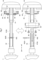
- Fig. 1 illustrates a tractor A (as an example of the "electric work vehicle” of the present invention) including left and right front wheels 10 (as an example of the “travel device” for the present invention), left and right rear wheels 11 (as an example of the “travel device” for the present invention), a cover member 12, and a tiller device 13.
- the tractor A further includes a body frame 2 and a driver section 3.
- the body frame 2 is supported by the left and right front wheels 10 and the left and right rear wheels 11.
- the tiller device 13 is supported by a back portion of the body frame 2.
- the cover member 12 is at a front portion of the machine body.
- the driver section 3 is behind the cover member 12.
- the driver section 3 includes a protection frame 30, a driver's seat 31, a steering wheel 32, and a floor 33. An operator can sit on the driver's seat 31 and perform various drive operations in the driver section 3.
- Operating the steering wheel 32 changes the direction of the left and right front wheels 10. The operator can place their feet on the floor 33 when sitting on the driver's seat 31.
- the tractor A in other words, includes a driver section 3 including a driver's seat 31 on which an operator is able to sit.
- the tractor A further includes a travel battery 4 (as an example of the "battery” for the present invention), a motor M, a transmission device T, and a front transmission mechanism FT.
- a travel battery 4 as an example of the "battery” for the present invention
- a motor M for the present invention
- a transmission device T for the present invention
- FT front transmission mechanism
- the cover member 12 is swingable about an open/close axis Q (see Fig. 2 ) extending in the left-right direction of the machine body. This allows the cover member 12 to be opened and closed.
- the travel battery 4 supplies electric power to the motor M.
- the motor M is under the travel battery 4.
- the motor M is driven on electric power supplied by the travel battery 4, and transmits its driving force to the transmission device T.
- the transmission device T is backward of the travel battery 4 and behind the motor M.
- the front transmission mechanism FT extends forward from the transmission device T.
- the transmission device T varies the driving force received from the motor M, and transmits the resulting driving force to the left and right rear wheels 11 as well as to the left and right front wheels 10 via the front transmission mechanism FT. This drives the left and right front wheels 10 and the left and right rear wheels 11.
- the tractor A in other words, includes a motor M positioned under the travel battery 4 and drivable on electric power supplied by the travel battery 4.
- the tractor A also includes left and right front wheels 10 and left and right rear wheels 11 drivable by the motor M.
- the tractor A as described above, includes a transmission device T positioned backward of the travel battery 4 and configured to transmit the driving force of the motor M to the left and right front wheels 10 and the left and right rear wheels 11.
- the transmission device T transmits part of the driving force received from the motor M to the tiller device 13. This drives the tiller device 13.
- the above configuration allows the tractor A to travel with use of the left and right front wheels 10 and the left and right rear wheels 11 and simultaneously perform tillage work with use of the tiller device 13.
- the travel battery 4 is above the body frame 2.
- the body frame 2 and the travel battery 4 define a ventilation space S in-between.
- the tractor A in other words, includes a travel battery 4 above the body frame 2.
- the ventilation space S is capable of letting air through.
- the tractor A further includes an inverter 14 under the travel battery 4 and forward of the motor M.
- the inverter 14 converts direct-current electric power from the travel battery 4 into alternating-current electric power, and supplies the alternating-current electric power to the motor M.
- the tractor A in other words, includes an inverter 14 positioned under the travel battery 4 and forward of the motor M and configured to convert direct-current electric power from the travel battery 4 into alternating-current electric power and supply the alternating-current electric power to the motor M.
- the motor M and the inverter 14 are arranged in the front-back direction of the machine body.
- the inverter 14 and the travel battery 4 define a first space S1 in-between.
- the first space S1 is part of the ventilation space S, and is thus capable of letting air through.
- the motor M and the travel battery 4 define a second space S2 in-between.
- the second space S2 is part of the ventilation space S, and is thus capable of letting air through.
- the motor M is positioned in contact with the ventilation space S.
- the motor M is, in other words, in contact with the ventilation space S.
- the body frame 2 includes left and right main frames 20 and an inverter support 21.
- the left and right main frames 20 extend in the front-back direction of the machine body.
- the tractor A in other words, includes a left main frame 20 and a right main frame 20 both extending in the front-back direction of the machine body.
- the motor M is between the left and right main frames 20.
- the inverter support 21 extends over the left and right main frames 20, and is supported thereby.
- the inverter support 21 supports the inverter 14.
- the inverter 14 is, in other words, supported by the left main frame 20 and the right main frame 20 with the inverter support 21 in-between.
- Fig. 3 shows a first left-end position LE1, a second left-end position LE2, and a third left-end position LE3.
- the first left-end position LE1 coincides with the left end of the left main frame 20.
- the second left-end position LE2 coincides with the left end of the inverter 14.
- the third left-end position LE3 coincides with the left end of the inverter support 21.
- the second left-end position LE2 is leftward of the first left-end position LE1.
- the inverter 14 extends farther leftward than the left end of the left main frame 20.
- the third left-end position LE3 is leftward of the first left-end position LE1 and the second left-end position LE2.
- the inverter support 21 extends farther leftward than the left end of the left main frame 20.
- Fig. 3 also shows a first right-end position RE1, a second right-end position RE2, and a third right-end position RE3.
- the first right-end position RE1 coincides with the right end of the right main frame 20.
- the second right-end position RE2 coincides with the right end of the inverter 14.
- the third right-end position RE3 coincides with the right end of the inverter support 21.
- the second right-end position RE2 is rightward of the first right-end position RE1.
- the inverter 14 extends farther rightward than the right end of the right main frame 20.
- the third right-end position RE3 is rightward of the first right-end position RE1 and the second right-end position RE2.
- the inverter support 21 extends farther rightward than the right end of the right main frame 20.
- the inverter 14 in other words, extends farther leftward than the left end of the left main frame 20 and farther rightward than the right end of the right main frame 20.
- the inverter support 21 also extends farther leftward than the left end of the left main frame 20 and farther rightward than the right end of the right main frame 20.
- the tractor A includes left and right first support frames 51 (as an example of the "battery support frames” for the present invention), left and right second support frames 52 (as an example of the "battery support frames” for the present invention), and a battery support 53.
- the left and right first support frames 51 are forward of the left and right second support frames 52.
- the left and right first support frames 51 and the left and right second support frames 52 all stand on the inverter support 21.
- the left and right first support frames 51 and the left and right second support frames 52 stand on the body frame 2.
- the tractor A further includes a plate-shaped support 38 and a plate-shaped partition member 56 (described later) between the motor M and the travel battery 4.
- the plate-shaped support 38 and the plate-shaped partition member 56 are each oriented horizontally.
- the plate-shaped partition member 56 is over the plate-shaped support 38.
- the tractor A further includes a back portion support frame 59 supported by the body frame 2.
- the back portion support frame 59 supports a back end portion of the battery support 53 with the plate-shaped support 38 and the plate-shaped partition member 56 in-between.
- the battery support 53 is above the body frame 2, and is supported by the left and right first support frames 51, the left and right second support frames 52, and the back portion support frame 59.
- the battery support 53 supports the travel battery 4.
- the tractor A in other words, includes a battery support 53 positioned above the body frame 2 and supporting the travel battery 4.
- the travel battery 4 is supported by the inverter support 21 with the battery support 53, the left and right first support frames 51, and the left and right second support frames 52 in-between.
- the travel battery 4 is, in other words, supported by the inverter support 21 with the left and right first support frames 51 in-between, which stand on the inverter support 21.
- the travel battery 4 is supported by the inverter support 21 with the left and right second support frames 52 in-between, which stand on the inverter support 21.
- the tractor A has a left ventilation opening K defined by the body frame 2, the battery support 53, the left first support frame 51, and the left second support frame 52.
- the tractor A also has a right ventilation opening K defined by the body frame 2, the battery support 53, the right first support frame 51, and the right second support frame 52.
- the left and right ventilation openings K each communicate with the ventilation space S.
- the ventilation space S communicates with the left and right ventilation openings K.
- the battery support 53 includes a bottom plate 53a (as an example of the "partition plate” for the present invention).
- the bottom plate 53a is oriented horizontally, and serves as a partition between the travel battery 4 and the inverter 14.
- the tractor A in other words, includes a bottom plate 53a as a partition between the travel battery 4 and the inverter 14.
- the tractor A includes a first plate-shaped member 54 and a second plate-shaped member 55.
- the first plate-shaped member 54 and the second plate-shaped member 55 each extend from one of the left and right main frames 20 to the other.
- the first plate-shaped member 54 is forward of the second plate-shaped member 55.
- the first plate-shaped member 54 and the second plate-shaped member 55 are each held in position by the left and right main frames 20.
- the body frame 2 holds the first plate-shaped member 54 and the second plate-shaped member 55 in position.
- the first plate-shaped member 54 and the second plate-shaped member 55 are below the ventilation space S, and are oriented horizontally.
- the cover member 12 includes an inlet section 12a.
- the inlet section 12a is capable of letting outside air into the cover member 12.
- the inlet section 12a is at a front end portion of the cover member 12.
- the inlet section 12a for the present embodiment is in the form of a plurality of small holes.
- the present invention is, however, not limited to such an arrangement.
- the inlet section 12a may alternatively be in any other form.
- the inlet section 12a may, for instance, be in the form of a single hole, or include a blower to let outside air in.
- the cover member 12 includes left and right outlet sections 12b.
- the left and right outlet sections 12b are each capable of letting air out of the cover member 12.
- the cover member 12 in other words, includes left and right outlet sections 12b each capable of letting air out of the cover member 12.
- the left outlet section 12b is at a left side portion of the cover member 12, whereas the right outlet section 12b is at a right side portion of the cover member 12.
- the left outlet section 12b is leftward of the travel battery 4.
- the right outlet section 12b is rightward of the travel battery 4.
- the left and right outlet sections 12b are, in other words, each lateral to the travel battery 4.
- the left and right outlet sections 12b for the present embodiment are each in the form of a plurality of small holes.
- the present invention is, however, not limited to such an arrangement.
- the left and right outlet sections 12b may each alternatively be in any other form.
- the left and right outlet sections 12b may each, for instance, be in the form of a single hole, or include a blower to let air out.
- the tractor A includes a radiator 15 and a water pump 16.
- the radiator 15 is forward of the travel battery 4.
- the tractor A in other words, includes a radiator 15 forward of the travel battery 4.
- the radiator 15 and the water pump 16 are included in a cooling water path of the tractor A.
- the water pump 16 forces cooling water to circulate through the cooling water path.
- the cooling water is cooled by the radiator 15 as it passes therethrough.
- the tractor A in other words, includes a water pump 16 to force cooling water to pass through a radiator 15.
- the water pump 16 is forward of the motor M and below the inverter 14.
- the water pump 16 is supported by the first plate-shaped member 54.
- the tractor A further includes a cooling fan 17.
- the cooling fan 17 is in front of the travel battery 4.
- the cooling fan 17 is, in other words, forward of the travel battery 4.
- the tractor A in other words, includes a cover member 12 capable of accommodating the cooling fan 17 and the travel battery 4.
- the cooling fan 17 extends in the up-down direction of the machine body to face both the travel battery 4 and the ventilation space S.
- the cooling fan 17 also extends in the up-down direction of the machine body to face both the travel battery 4 and the inverter 14.
- the cooling fan 17 blows cooling air backward. This causes outside air to enter the cover member 12 through the inlet section 12a and pass through the radiator 15, thereby cooling the radiator 15.
- the cooling fan 17 is, in other words, forward of the travel battery 4, and cools the radiator 15.
- the cooling fan 17 sends cooling air to a front portion of the travel battery 4 and to the ventilation space S.
- the tractor A in other words, includes a cooling fan 17 positioned forward of the travel battery 4 and configured to send cooling air to the travel battery 4.
- the cooling fan 17 sends cooling air to a front portion of the travel battery 4, at least a portion of which cooling air flows to a space leftward of the travel battery 4 and to a space rightward of the travel battery 4 to be let out through the left and right outlet sections 12b. This cools the front portion and lateral side portions of the travel battery 4.
- the cooling fan 17 sends cooling air to the ventilation space S, a portion of which cooling air reaches the first space S1 and then passes through the left and right ventilation openings K and the left and right outlet sections 12b to be let out of the cover member 12.
- the tractor A includes a horizontally oriented plate-shaped partition member 56 between the battery support 53 and the motor M.
- the plate-shaped partition member 56 includes a wind guide plate 56a.
- the wind guide plate 56a is a front end portion of the plate-shaped partition member 56 which is bent downward.
- the wind guide plate 56a is thus oriented vertically, and faces toward the cooling fan 17.
- the tractor A in other words, includes a wind guide plate 56a facing toward the cooling fan 17.
- the wind guide plate 56a is under the travel battery 4 and forward of the second space S2.
- the tractor A includes a reserve tank 5 for the radiator 15.
- the reserve tank 5 stores cooling water.
- the reserve tank 5 is forward of the travel battery 4 and rightward of the radiator 15.
- the tractor A includes an auxiliary battery 18 and a voltage converter 19.
- the auxiliary battery 18 supplies electric power to various auxiliaries such as the cooling fan 17.
- the travel battery 4 transmits electric power to the voltage converter 19, which then steps down the voltage of the electric power and supplies the resulting electric power to the auxiliary battery 18.
- the tractor A in other words, includes a voltage converter 19 positioned forward of the travel battery 4 and configured to step down the voltage of electric power from the travel battery 4 and supply the resulting electric power to the auxiliary battery 18.
- the auxiliary battery 18 and the voltage converter 19 are forward of the travel battery 4 and rightward of the radiator 15.
- the voltage converter 19 is oriented to have a longitudinal direction extending in the up-down direction of the machine body.
- the voltage converter 19 and the radiator 15 are laterally next to each other in a plan view.
- the radiator 15, the voltage converter 19, and the auxiliary battery 18 are laterally next to one another in a plan view.
- the voltage converter 19 is between the radiator 15 and the auxiliary battery 18 in a plan view.
- the radiator 15, the voltage converter 19, and the reserve tank 5 are laterally next to one another in a plan view.
- the voltage converter 19 is between the radiator 15 and the reserve tank 5 in a plan view.
- the reserve tank 5 is over the auxiliary battery 18.
- the reserve tank 5 and the auxiliary battery 18 are arranged in the up-down direction of the machine body.
- the tractor A includes an oil cooler CL.
- the oil cooler CL cools operating oil of the tractor A as it passes through the oil cooler CL.
- the radiator 15 is held in place by a radiator frame 57 in the shape of an angular arch.
- the radiator frame 57 surrounds the radiator 15.
- the tractor A in other words, includes a radiator frame 57 having a shape of an angular arch surrounding the radiator 15 and holding the radiator 15 in place.
- the radiator frame 57 includes a left side plate 57a, a top plate 57b, a right side plate 57c, a first top plate support 57d, and a second top plate support 57e.
- the left side plate 57a is a left portion of the radiator frame 57.
- the top plate 57b is a top portion of the radiator frame 57.
- the right side plate 57c is a right portion of the radiator frame 57.
- the left side plate 57a and the right side plate 57c are each oriented vertically, and are arranged in the left-right direction.
- the left side plate 57a and the right side plate 57c face each other.
- the first top plate support 57d extends leftward from an upper end portion of the left side plate 57a.
- the second top plate support 57e extends rightward from an upper end portion of the right side plate 57c.
- the top plate 57b is placed on and supported by the upper face of the first top plate support 57d and the upper face of the second top plate support 57e.
- the voltage converter 19 is attached to the radiator frame 57. Specifically, the voltage converter 19 is attached to the right face of the right side plate 57c.
- the tractor A includes a first hose 6a, a second hose 6b, a water supply section 6c, and a third hose 6d, which are included in the cooling water path of the tractor A.
- the first hose 6a has a first end connected to the radiator 15 and a second end connected to the water supply section 6c.
- the tractor A in other words, includes a first hose 6a connected to the radiator 15.
- the second hose 6b has a first end connected to the water supply section 6c and a second end connected to the voltage converter 19.
- the third hose 6d is connected to the voltage converter 19.
- An operator can supply cooling water into the water supply section 6c.
- the cooling water flows sequentially through the third hose 6d, the voltage converter 19, the second hose 6b, the water supply section 6c, the first hose 6a, and the radiator 15.
- the tractor A includes a support 7 and a cover support 58.
- the support 7 is supported by the radiator frame 57, and extends upward from an upper portion of the radiator frame 57.
- the tractor A in other words, includes a support 7 extending upward from an upper portion of the radiator frame 57.
- the cover support 58 is in the shape of a bar.
- the cover support 58 has a first end portion coupled to an upper end portion of the support 7 in such a manner as to be swingable in the up-down direction about a swing axis P extending in the front-back direction of the machine body.
- the above configuration allows the cover support 58 to support the cover member 12 in the open state.
- the tractor A in other words, includes a cover support 58 coupled to an upper end portion of the support 7 and capable of supporting the cover member 12 in the open state.
- the cover member 12 in the closed state, accommodates the voltage converter 19, the first hose 6a, the radiator frame 57, the reserve tank 5, and the auxiliary battery 18.
- the tractor A in other words, includes a cover member 12 capable of being opened and closed and of accommodating the voltage converter 19, the radiator 15, the first hose 6a, and the radiator frame 57.
- the support 7 includes a first portion 71, a second portion 72, and a third portion 73.
- the first portion 71 extends upward from an upper portion of the radiator frame 57.
- the first portion 71 has a lower end portion connected to the upper portion of the radiator frame 57.
- the second portion 72 extends forward from a middle portion of the first portion 71 in the up-down direction of the machine body.
- the second portion 72 is oriented horizontally.
- the third portion 73 extends substantially downward from a front end portion of the second portion 72, and is connected to an upper portion of the radiator frame 57.
- the third portion 73 is oriented obliquely in a lower front direction.
- the third portion 73 has a back end portion connected to the front end portion of the second portion 72, and has a front end portion connected to the upper portion of the radiator frame 57.
- the support 7 in other words, includes (i) a first portion 71 extending upward from an upper portion of the radiator frame 57, (ii) a second portion 72 extending forward from a middle portion of the first portion 71 in the up-down direction of the machine body, and (iii) a third portion 73 extending substantially downward from a front end portion of the second portion 72 and connected to an upper portion of the radiator frame 57.
- the first hose 6a extends through an area AR defined by the first portion 71, the second portion 72, and the third portion 73.
- the description below deals with the first portion 71 in detail.
- the first portion 71 includes a support stay 71a and a vertical fixed portion 71b.
- the support stay 71a is in the shape of a long plate, and extends in the up-down direction of the machine body along the left side plate 57a.
- the support stay 71a has a lower end portion bolted to a back end portion of an upper end portion of the left side plate 57a.
- the vertical fixed portion 71b is in the shape of a long plate, and extends in the up-down direction of the machine body.
- the vertical fixed portion 71b has a dimension smaller than the support stay 71a in the up-down direction of the machine body.
- the vertical fixed portion 71b is perpendicular to the support stay 71a, and is fixed to its left face.
- the vertical fixed portion 71b, the second portion 72, and the third portion 73 are integral with one another.
- the above-mentioned area AR is defined by the support stay 71a, the second portion 72, and the third portion 73.
- the tractor A includes a horizontally oriented support plate SP at a front portion thereof.
- the support plate SP supports the radiator 15, the cooling fan 17, the auxiliary battery 18, the voltage converter 19, the radiator frame 57, and the oil cooler CL.
- the tractor A includes a hydraulic pump 60.
- the hydraulic pump 60 supplies operating oil to an operating mechanism for operating the tiller device 13.
- the hydraulic pump 60 controls the supply of operating oil to operate the tiller device 13.
- the tractor A includes a lifting/lowering mechanism 36 as an operating mechanism for a work device.
- the hydraulic pump 60 supplies operating oil to the lifting/lowering mechanism 36 to operate the lifting/lowering mechanism 36, which then lifts and lowers the tiller device 13.
- the tiller device 13 includes a tiller section 13a with a drive section connected to a PTO shaft 37 of the tractor A.
- the tiller device 13 performs tillage work with use of power from the PTO shaft 37.
- the hydraulic pump 60 is next to the motor M.
- the motor M is held in place by a front portion support frame 50 and a back portion support frame 59.
- the front portion support frame 50 extends from one of the left and right main frames 20 to the other, and is fixed to respective lower portions of the left and right main frames 20.
- the front portion support frame 50 is under a front portion of the motor M and supports it.
- the back portion support frame 59 extends beyond the left and right main frames 20.
- the back portion support frame 59 is in contact with a back end portion of the motor M and holds a back portion of the motor M in place.
- the hydraulic pump 60 is in front of and attached to the back portion support frame 59.
- the hydraulic pump 60 is held in place by the back portion support frame 59.
- the motor M and the hydraulic pump 60 are both held in place by the same back portion support frame 59.
- the motor M includes a motor output shaft 61 as its output shaft.
- the motor output shaft 61 is provided with a first rotor 64 configured to rotate integrally with the motor output shaft 61.
- the tractor A in other words, includes a first rotor 64 attached to the motor output shaft 61 and configured to rotate integrally with the motor output shaft 61.
- the hydraulic pump 60 includes a pump input shaft 62 as its input shaft.
- the pump input shaft 62 is provided with a second rotor 65 configured to rotate integrally with the pump input shaft 62.
- the tractor A in other words, includes a second rotor 65 attached to the pump input shaft 62 as an input shaft of the hydraulic pump 60 and configured to rotate integrally with the pump input shaft 62.
- the tractor A also includes an endless rotary body 66 wound around the first rotor 64 and the second rotor 65.
- the tractor A in other words, includes an endless rotary body 66 windable around the first rotor 64 and the second rotor 65.
- the endless rotary body 66 for the present embodiment is a belt.
- the present invention is, however, not limited to such an arrangement.
- the endless rotary body 66 is not necessarily a belt, and may be a chain, for example.
- the above configuration allows the motor M to transmit its driving force to the hydraulic pump 60 via the motor output shaft 61, the first rotor 64, the endless rotary body 66, the second rotor 65, and the pump input shaft 62. This drives the hydraulic pump 60.
- the tractor A in other words, includes a hydraulic pump 60 drivable by the motor M to supply operating oil to the tiller device 13.
- the transmission device T includes a transmission input shaft 63 as its input shaft.
- the transmission input shaft 63 is coupled to the motor output shaft 61 with a coupling section 8. This allows the transmission input shaft 63 to rotate integrally with the motor output shaft 61.
- the motor output shaft 61 and the transmission input shaft 63 are each in the shape of a cylinder extending in the front-back direction of the machine body.
- the coupling section 8 includes a coupling shaft 81 and a pin 82.
- the coupling shaft 81 extends in the front-back direction of the machine body.
- the coupling shaft 81 has a front end portion inserted in the motor output shaft 61 and in spline engagement therewith.
- the coupling shaft 81 has a back end portion inserted in the transmission input shaft 63 and in spline engagement therewith.
- the transmission input shaft 63 has a pin hole 63a, in which the pin 82 is insertable.
- the pin 82 is, when inserted, behind the coupling shaft 81 to prevent it from sliding backward.
- the tractor A in other words, includes a coupling section 8 configured to couple the transmission input shaft 63 and the motor output shaft 61 to each other in such a manner that the transmission input shaft 63 and the motor output shaft 61 are incapable of rotation relative to each other.
- the coupling section 8 is switchable between a coupling state and a non-coupling state.
- the coupling state the coupling section 8 couples the transmission input shaft 63 and the motor output shaft 61 to each other.
- the non-coupling state the coupling section 8 does not couple the transmission input shaft 63 and the motor output shaft 61 to each other.
- Fig. 7 illustrates on the left side the coupling section 8 in the coupling state.
- the transmission input shaft 63 and the motor output shaft 61 are incapable of rotation relative to each other as described above.
- the transmission input shaft 63 thus rotates integrally with the motor output shaft 61.
- the coupling section 8 is in the state illustrated on the right side of Fig. 7 , that is, in the non-coupling state.
- the coupling shaft 81 is apart from the motor output shaft 61, with a gap G between the front end of the coupling shaft 81 and the back end of the motor output shaft 61.
- the gap G is between the front end of the transmission input shaft 63 and the back end of the motor output shaft 61, and is larger than the width of the endless rotary body 66. This allows the endless rotary body 66 to pass through the gap G in a case where the endless rotary body 66 has been removed from the first rotor 64 or the second rotor 65.
- the front end of the transmission input shaft 63 and the back end of the motor output shaft 61 define a gap G that allows the endless rotary body 66 to pass therethrough in a case where the endless rotary body 66 has been removed.
- the first rotor 64 includes a first segment 67 and a second segment 68.
- the first segment 67 is forward of the second segment 68.
- the second segment 68 has a front face in contact with the back face of the first segment 67.
- the first segment 67 includes a wind-around section 67a and a flange section 67b.
- the wind-around section 67a allows the endless rotary body 66 to be wound therearound.
- the flange section 67b protrudes radially at a front end portion of the first segment 67.
- the second segment 68 is in the shape of a disk.
- the second segment 68 is fixed to the back end of the wind-around section 67a with use of a plurality of fixation bolts 69.
- the second segment 68 has an outer diameter equal to that of the flange section 67b.
- an operator can pass the endless rotary body 66 through the gap G, wind the endless rotary body 66 around the wind-around section 67a, and then fix the second segment 68 as illustrated on the left side of Fig. 7 .
- the operator can easily attach the endless rotary body 66 to the tractor A as such.
- the tractor A includes a tension adjusting mechanism 9.
- the tension adjusting mechanism 9 includes a tension ring 91, a long linkage member 92, and an adjuster 93.
- the tension ring 91 is in contact with the endless rotary body 66, and applies tension thereto.
- the tension ring 91 is supported by the body frame 2 with the linkage member 92 in-between.
- the adjuster 93 is manually operable. Manually operating the adjuster 93 moves the linkage member 92 in its longitudinal direction. The movement of the linkage member 92 causes the tension ring 91 to also move in the longitudinal direction of the linkage member 92. This changes the tension of the endless rotary body 66.
- the tension adjusting mechanism 9 is manually operable to adjust the tension of the endless rotary body 66.
- the tractor A in other words, includes a tension adjusting mechanism 9 manually operable to adjust the tension of the endless rotary body 66.
- the driver section 3 includes a wall 34 and an opening cover member 35.
- the wall 34 serves as a partition that separates the driver's seat 31 from the endless rotary body 66 and the tension adjusting mechanism 9.
- the wall 34 has an opening 34a in the vicinity of the tension adjusting mechanism 9.
- the opening 34a is also in the vicinity of the front end of the floor 33.
- the opening cover member 35 is detachably attached to the wall 34 to close the opening 34a. Detaching the opening cover member 35 exposes the opening 34a. Attaching the opening cover member 35 closes the opening 34a.
- the opening cover member 35 is attached to the wall 34 with use of a bolt(s) b1. Removing the bolt b1 allows the opening cover member 35 to be detached. While Fig. 8 shows only one bolt b1, the number of bolts b1 may be any number of one or more.
- the driver section 3 in other words, includes a wall 34 as a partition that separates the driver's seat 31 from the endless rotary body 66 and the tension adjusting mechanism 9.
- the driver section 3 also includes an opening cover member 35 capable of exposing and closing the opening 34a.
- the present invention is, however, not limited to such an arrangement.
- the opening cover member 35 may be attachable to the wall 34 without use of a bolt b1.
- the present invention may be arranged such that the opening cover member 35 has a protrusion, whereas the wall 34 has a depression and that fitting the protrusion into the depression causes the opening cover member 35 to be attached to the wall 34.
- An operator can remove the opening cover member 35 to easily reach the adjuster 93 through the opening 34a.
- the transmission device T is backward of the travel battery 4. This allows the travel battery 4 and the transmission device T to be positioned differently in the front-back direction of the machine body.
- the above configuration thereby allows the machine body to have a weight well-balanced in the front-back direction as compared to a case of a transmission device T being under a travel battery 4.
- the motor M and the inverter 14 are positioned under the travel battery 4 and arranged in the front-back direction of the machine body.
- the machine body thus uses only a relatively small space in its left-right direction for the travel battery 4, the motor M, and the inverter 14.
- the machine body as a result, has an advantageously small width.
- the motor M is backward of the inverter 14. This eliminates the need for additional care to be taken so that the structure for power transmission from the motor M to the transmission device T will bypass the inverter 14. This in turn simplifies the structure for power transmission from the motor M to the transmission device T.
- the configuration described above therefore allows production of a tractor A including (i) a machine body that has a weight well-balanced in the front-back direction and that has an advantageously small width and (ii) a simple structure for power transmission from the motor M to the transmission device T.
- the present invention is applicable to not only tractors but also various electric work vehicles such as combines, rice transplanters, and construction machines.
Landscapes
- Engineering & Computer Science (AREA)
- Mechanical Engineering (AREA)
- Transportation (AREA)
- Chemical & Material Sciences (AREA)
- Combustion & Propulsion (AREA)
- Life Sciences & Earth Sciences (AREA)
- Sustainable Development (AREA)
- Sustainable Energy (AREA)
- Power Engineering (AREA)
- Structural Engineering (AREA)
- Architecture (AREA)
- Arrangement Or Mounting Of Propulsion Units For Vehicles (AREA)
- Cooling, Air Intake And Gas Exhaust, And Fuel Tank Arrangements In Propulsion Units (AREA)
- Electric Propulsion And Braking For Vehicles (AREA)
- Arrangement And Driving Of Transmission Devices (AREA)
Claims (6)
- Elektrisches Nutzfahrzeug, umfassend:- eine Batterie (4);- einen Motor (M), der unter der Batterie (4) positioniert ist und mit elektrischem Strom angetrieben werden kann, der von der Batterie (4) zugeführt wird;- eine Fahrvorrichtung (10, 11), die von dem Motor (M) angetrieben werden kann;- einen Wechselrichter (14), der unter der Batterie (4) und vor dem Motor (M) positioniert ist und eingerichtet ist, elektrischen Gleichstrom von der Batterie (4) in elektrischen Wechselstrom umzuwandeln und den elektrischen Wechselstrom dem Motor (M) zuzuführen; und- eine Übertragungsvorrichtung (T), die hinter der Batterie (4) positioniert ist und eingerichtet ist, eine Antriebskraft des Motors (M) auf die Fahrvorrichtung (10, 11) zu übertragen,wobei der Motor (M) und der Wechselrichter (14) in einer Richtung von vorne nach hinten eines Maschinenkörpers angeordnet sind,
dadurch gekennzeichnet, dass das elektrische Nutzfahrzeug ferner Folgendes umfasst:- einen Kühler (15); und- eine Wasserpumpe (16), die vor dem Motor (M) und unterhalb des Wechselrichters (14) positioniert ist und eingerichtet ist, Kühlwasser dazu zu zwingen, durch den Kühler (15) zu fließen. - Elektrisches Nutzfahrzeug nach Anspruch 1, ferner umfassend:- einen linken Hauptrahmen (20) und einen rechten Hauptrahmen (20), die sich beide in der Richtung von vorne nach hinten des Maschinenkörpers erstrecken,- wobei der Wechselrichter (14) von dem linken Hauptrahmen (20) und dem rechten Hauptrahmen (20) gestützt wird, und- sich der Motor (M) zwischen dem linken Hauptrahmen (20) und dem rechten Hauptrahmen (20) befindet.
- Elektrisches Nutzfahrzeug nach Anspruch 1 oder 2, ferner umfassend:- einen linken Hauptrahmen (20) und einen rechten Hauptrahmen (20), die sich beide in der Richtung von vorne nach hinten des Maschinenkörpers erstrecken,- wobei der Wechselrichter (14) von dem linken Hauptrahmen (20) und dem rechten Hauptrahmen (20) gestützt wird, und- sich der Wechselrichter (14) weiter nach links als ein linkes Ende des linken Hauptrahmens (20) und weiter nach rechts als ein rechtes Ende des rechten Hauptrahmens (20) erstreckt.
- Elektrisches Nutzfahrzeug nach Anspruch 3, ferner umfassend:- eine Wechselrichterhalterung (21) zwischen dem Wechselrichter (14) und dem Hauptrahmen (20),- wobei sich die Wechselrichterhalterung (21) weiter nach links als das linke Ende des linken Hauptrahmens (20) und weiter nach rechts als das rechte Ende des rechten Hauptrahmens (20) erstreckt, und- die Batterie (4) von der Wechselrichterhalterung (21) mit einem linken Batteriestützrahmen (51, 52) und einem rechten Batteriestützrahmen (51, 52) dazwischen gestützt wird, wobei der linke Batteriestützrahmen (51, 52) und der rechte Batteriestützrahmen (51, 52) auf der Wechselrichterhalterung (21) stehen.
- Elektrisches Nutzfahrzeug nach einem der Ansprüche 1 bis 4, ferner umfassend:
eine Trennplatte (53a) zwischen der Batterie (4) und dem Wechselrichter (14). - Elektrisches Nutzfahrzeug nach einem der Ansprüche 1 bis 5, ferner umfassend:- einen Kühler (15) vor der Batterie (4); und- ein Kühlgebläse (17), das vor der Batterie (4) positioniert ist und eingerichtet ist, den Kühler (15) zu kühlen,- wobei sich das Kühlgebläse (17) in der Richtung von oben nach unten des Maschinenkörpers erstreckt, so dass es sowohl der Batterie (4) als auch dem Wechselrichter (14) gegenüberliegt, und Kühlluft nach hinten schickt.
Applications Claiming Priority (2)
| Application Number | Priority Date | Filing Date | Title |
|---|---|---|---|
| JP2019116724A JP7323349B2 (ja) | 2019-06-24 | 2019-06-24 | 電動作業車 |
| PCT/JP2020/020874 WO2020261847A1 (ja) | 2019-06-24 | 2020-05-27 | 電動作業車 |
Publications (3)
| Publication Number | Publication Date |
|---|---|
| EP3988366A1 EP3988366A1 (de) | 2022-04-27 |
| EP3988366A4 EP3988366A4 (de) | 2023-08-30 |
| EP3988366B1 true EP3988366B1 (de) | 2025-07-02 |
Family
ID=73993749
Family Applications (1)
| Application Number | Title | Priority Date | Filing Date |
|---|---|---|---|
| EP20832859.1A Active EP3988366B1 (de) | 2019-06-24 | 2020-05-27 | Elektrisches nutzfahrzeug |
Country Status (5)
| Country | Link |
|---|---|
| US (1) | US12157360B2 (de) |
| EP (1) | EP3988366B1 (de) |
| JP (3) | JP7323349B2 (de) |
| CN (1) | CN113710523B (de) |
| WO (1) | WO2020261847A1 (de) |
Families Citing this family (25)
| Publication number | Priority date | Publication date | Assignee | Title |
|---|---|---|---|---|
| JP7224245B2 (ja) * | 2019-06-24 | 2023-02-17 | 株式会社クボタ | 電動作業車 |
| JP7323349B2 (ja) * | 2019-06-24 | 2023-08-08 | 株式会社クボタ | 電動作業車 |
| JP7206182B2 (ja) | 2019-12-26 | 2023-01-17 | 株式会社クボタ | 電動作業車 |
| DE112021007129T5 (de) * | 2021-02-18 | 2024-01-04 | Honda Motor Co., Ltd. | Fahrzeug |
| JP2022126494A (ja) * | 2021-02-18 | 2022-08-30 | 株式会社 神崎高級工機製作所 | 電動車両 |
| JP7498683B2 (ja) * | 2021-06-29 | 2024-06-12 | 株式会社クボタ | 電動作業車 |
| US12319134B2 (en) * | 2021-10-29 | 2025-06-03 | Yanmar Holdings Co., Ltd. | Electric tractor |
| EP4454917A1 (de) | 2021-12-24 | 2024-10-30 | Kubota Corporation | Elektrisches arbeitsfahrzeug |
| JP7519983B2 (ja) * | 2021-12-24 | 2024-07-22 | 株式会社クボタ | 電動作業車 |
| EP4456404A4 (de) * | 2021-12-24 | 2025-12-10 | Kubota Kk | Elektrisches arbeitsfahrzeug |
| JP7519982B2 (ja) * | 2021-12-24 | 2024-07-22 | 株式会社クボタ | 電動作業車 |
| JP2023110659A (ja) * | 2022-01-28 | 2023-08-09 | 株式会社クボタ | 電動作業車 |
| JP7720799B2 (ja) * | 2022-02-01 | 2025-08-08 | 株式会社クボタ | 電動作業車 |
| JP7756600B2 (ja) * | 2022-06-03 | 2025-10-20 | 株式会社クボタ | 作業車 |
| EP4529752A4 (de) * | 2022-06-28 | 2025-09-10 | Kubota Kk | Landwirtschaftlicher traktor |
| JP7792880B2 (ja) * | 2022-09-26 | 2025-12-26 | 株式会社クボタ | 作業車 |
| JP2024078568A (ja) * | 2022-11-30 | 2024-06-11 | ヤンマーホールディングス株式会社 | 電動式作業機械 |
| AU2022490886A1 (en) * | 2022-12-22 | 2025-06-05 | Epiroc Rock Drills Aktiebolag | Dc-charging system |
| WO2024143226A1 (ja) * | 2022-12-27 | 2024-07-04 | 株式会社クボタ | 電動作業車 |
| US20250121669A1 (en) * | 2023-10-13 | 2025-04-17 | Kubota Corporation | Electric motor supporting arrangement for vehicles |
| US20250121662A1 (en) * | 2023-10-13 | 2025-04-17 | Kubota Corporation | Electric motor supporting arrangement for vehicles |
| US20250135861A1 (en) * | 2023-10-30 | 2025-05-01 | Kubota Corporation | Component layout of electric components in electric work vehicle |
| US20250140958A1 (en) * | 2023-10-30 | 2025-05-01 | Kubota Corporation | Component layout of air cooling components in electric work vehicle |
| WO2025142304A1 (ja) * | 2023-12-27 | 2025-07-03 | 株式会社クボタ | 電動トラクタ |
| WO2025142225A1 (ja) * | 2023-12-27 | 2025-07-03 | 株式会社クボタ | 電動トラクタ |
Family Cites Families (36)
| Publication number | Priority date | Publication date | Assignee | Title |
|---|---|---|---|---|
| JP2585281Y2 (ja) * | 1992-04-30 | 1998-11-18 | 三菱農機株式会社 | 電動農用トラクタ |
| US7051786B2 (en) * | 2003-07-11 | 2006-05-30 | Deere & Company | Vertical airflow engine cooling system |
| JP5028560B2 (ja) | 2007-04-24 | 2012-09-19 | 株式会社 神崎高級工機製作所 | 乗用型芝刈り車両 |
| JP5252311B2 (ja) * | 2009-09-25 | 2013-07-31 | スズキ株式会社 | ハイブリッド車両の冷却装置 |
| US8616310B2 (en) | 2011-01-14 | 2013-12-31 | Gilbert T. Lopez | Apparatus for farming, gardening and landscaping |
| JP5814578B2 (ja) | 2011-03-24 | 2015-11-17 | 株式会社小松製作所 | 電動式作業車両及びそのベースフレーム |
| JP2012201188A (ja) | 2011-03-24 | 2012-10-22 | Komatsu Ltd | バッテリ駆動のホイールローダ |
| JP5821387B2 (ja) * | 2011-08-09 | 2015-11-24 | スズキ株式会社 | 車両のインバータ搭載構造 |
| KR101302405B1 (ko) | 2011-10-14 | 2013-09-02 | 대동공업주식회사 | 전기구동식 농용 작업차 구조 |
| JP5826042B2 (ja) | 2012-01-12 | 2015-12-02 | 株式会社クボタ | 電動作業車 |
| JP5757283B2 (ja) * | 2012-12-10 | 2015-07-29 | トヨタ自動車株式会社 | 電子機器の車載構造 |
| JP2014143965A (ja) | 2013-01-30 | 2014-08-14 | Iseki & Co Ltd | トラクタ |
| JP2013233929A (ja) * | 2013-07-10 | 2013-11-21 | Kubota Corp | 作業車 |
| CN105392650B (zh) * | 2013-08-09 | 2018-09-11 | 株式会社小松制作所 | 作业车辆 |
| KR20160072115A (ko) * | 2013-10-16 | 2016-06-22 | 가부시끼 가이샤 구보다 | 시리즈 하이브리드 콤바인 |
| JP5979175B2 (ja) * | 2014-04-21 | 2016-08-24 | トヨタ自動車株式会社 | 電気機器の車両への固定構造 |
| JP6132273B2 (ja) * | 2014-07-28 | 2017-05-24 | 日立建機株式会社 | ハイブリッド式作業機 |
| JP2016132326A (ja) * | 2015-01-16 | 2016-07-25 | トヨタ自動車株式会社 | 電気自動車、保持機構、及び電気自動車の製造方法 |
| JP6433367B2 (ja) * | 2015-04-08 | 2018-12-05 | 株式会社クボタ | 電動作業車両 |
| US10029551B2 (en) * | 2015-11-16 | 2018-07-24 | Kubota Corporation | Electric work vehicle, battery pack for electric work vehicle and contactless charging system |
| DE102016104453A1 (de) | 2016-03-11 | 2017-09-14 | Claas Tractor Sas | Landwirtschaftlicher Zug mit einem Zugfahrzeug und Anhänger |
| JP6664296B2 (ja) * | 2016-09-02 | 2020-03-13 | 株式会社クボタ | 作業車 |
| JP6675964B2 (ja) * | 2016-10-28 | 2020-04-08 | 株式会社クボタ | トラクター |
| JP6489187B1 (ja) * | 2017-09-19 | 2019-03-27 | マツダ株式会社 | 電気駆動車両構造 |
| US11345410B2 (en) * | 2017-10-23 | 2022-05-31 | Kubota Corporation | Work vehicle |
| CN109747401B (zh) * | 2017-11-02 | 2022-03-11 | 丰田自动车株式会社 | 车辆用高电压单元的支撑结构及车辆前部结构 |
| JP7304750B2 (ja) * | 2019-06-24 | 2023-07-07 | 株式会社クボタ | 電動作業車 |
| JP7224245B2 (ja) * | 2019-06-24 | 2023-02-17 | 株式会社クボタ | 電動作業車 |
| JP7323349B2 (ja) * | 2019-06-24 | 2023-08-08 | 株式会社クボタ | 電動作業車 |
| JP7321008B2 (ja) * | 2019-06-24 | 2023-08-04 | 株式会社クボタ | 電動作業車 |
| JP7246264B2 (ja) * | 2019-06-24 | 2023-03-27 | 株式会社クボタ | 電動作業車 |
| EP4227192A4 (de) * | 2020-10-05 | 2025-04-02 | Kubota Corporation | Elektrotraktor |
| US12319134B2 (en) * | 2021-10-29 | 2025-06-03 | Yanmar Holdings Co., Ltd. | Electric tractor |
| US11407298B1 (en) * | 2021-11-15 | 2022-08-09 | Amos Power, Inc. | Removable battery unit for an electric vehicle |
| JP7770255B2 (ja) * | 2022-06-03 | 2025-11-14 | 株式会社クボタ | 作業車 |
| JP2023178908A (ja) * | 2022-06-06 | 2023-12-18 | 株式会社 神崎高級工機製作所 | 電動作業車両 |
-
2019
- 2019-06-24 JP JP2019116724A patent/JP7323349B2/ja active Active
-
2020
- 2020-05-27 US US17/619,529 patent/US12157360B2/en active Active
- 2020-05-27 EP EP20832859.1A patent/EP3988366B1/de active Active
- 2020-05-27 CN CN202080028755.6A patent/CN113710523B/zh active Active
- 2020-05-27 WO PCT/JP2020/020874 patent/WO2020261847A1/ja not_active Ceased
-
2023
- 2023-07-26 JP JP2023121764A patent/JP7662718B2/ja active Active
-
2025
- 2025-04-03 JP JP2025061741A patent/JP2025098279A/ja active Pending
Also Published As
| Publication number | Publication date |
|---|---|
| JP2021000955A (ja) | 2021-01-07 |
| EP3988366A1 (de) | 2022-04-27 |
| EP3988366A4 (de) | 2023-08-30 |
| JP7662718B2 (ja) | 2025-04-15 |
| JP7323349B2 (ja) | 2023-08-08 |
| US20220379704A1 (en) | 2022-12-01 |
| WO2020261847A1 (ja) | 2020-12-30 |
| US12157360B2 (en) | 2024-12-03 |
| CN113710523B (zh) | 2024-10-08 |
| CN113710523A (zh) | 2021-11-26 |
| JP2025098279A (ja) | 2025-07-01 |
| JP2023156352A (ja) | 2023-10-24 |
Similar Documents
| Publication | Publication Date | Title |
|---|---|---|
| EP3988366B1 (de) | Elektrisches nutzfahrzeug | |
| EP3988364B1 (de) | Elektrisches nutzfahrzeug | |
| EP3987902B1 (de) | Elektrisches nutzfahrzeug | |
| JP2025098279A5 (de) | ||
| US12391110B2 (en) | Airflow arrangement for cooling an electric work vehicle | |
| US20240367725A1 (en) | Electric work vehicle including battery enclosure structure | |
| JP2021104768A (ja) | 電動作業車 | |
| JP7458956B2 (ja) | 電動トラクタ | |
| TW202517134A (zh) | 作業車輛 | |
| JP7546543B2 (ja) | 電動作業車 | |
| JP7702895B2 (ja) | 電動作業車 |
Legal Events
| Date | Code | Title | Description |
|---|---|---|---|
| STAA | Information on the status of an ep patent application or granted ep patent |
Free format text: STATUS: THE INTERNATIONAL PUBLICATION HAS BEEN MADE |
|
| PUAI | Public reference made under article 153(3) epc to a published international application that has entered the european phase |
Free format text: ORIGINAL CODE: 0009012 |
|
| STAA | Information on the status of an ep patent application or granted ep patent |
Free format text: STATUS: REQUEST FOR EXAMINATION WAS MADE |
|
| 17P | Request for examination filed |
Effective date: 20211125 |
|
| AK | Designated contracting states |
Kind code of ref document: A1 Designated state(s): AL AT BE BG CH CY CZ DE DK EE ES FI FR GB GR HR HU IE IS IT LI LT LU LV MC MK MT NL NO PL PT RO RS SE SI SK SM TR |
|
| DAV | Request for validation of the european patent (deleted) | ||
| DAX | Request for extension of the european patent (deleted) | ||
| A4 | Supplementary search report drawn up and despatched |
Effective date: 20230802 |
|
| RIC1 | Information provided on ipc code assigned before grant |
Ipc: B60L 58/26 20190101ALN20230727BHEP Ipc: B60L 50/60 20190101ALN20230727BHEP Ipc: B60K 17/28 20060101ALI20230727BHEP Ipc: B60K 11/02 20060101ALI20230727BHEP Ipc: B60K 11/00 20060101ALI20230727BHEP Ipc: B60K 1/00 20060101ALI20230727BHEP Ipc: F01P 3/18 20060101ALI20230727BHEP Ipc: F01P 3/12 20060101ALI20230727BHEP Ipc: F01P 11/10 20060101ALI20230727BHEP Ipc: B60K 1/04 20190101ALI20230727BHEP Ipc: B60L 15/00 20060101ALI20230727BHEP Ipc: B60K 11/04 20060101AFI20230727BHEP |
|
| GRAP | Despatch of communication of intention to grant a patent |
Free format text: ORIGINAL CODE: EPIDOSNIGR1 |
|
| STAA | Information on the status of an ep patent application or granted ep patent |
Free format text: STATUS: GRANT OF PATENT IS INTENDED |
|
| RIC1 | Information provided on ipc code assigned before grant |
Ipc: B60L 58/26 20190101ALN20241219BHEP Ipc: B60L 50/60 20190101ALN20241219BHEP Ipc: B60K 17/28 20060101ALI20241219BHEP Ipc: B60K 11/02 20060101ALI20241219BHEP Ipc: B60K 11/00 20060101ALI20241219BHEP Ipc: B60K 1/00 20060101ALI20241219BHEP Ipc: F01P 3/18 20060101ALI20241219BHEP Ipc: F01P 3/12 20060101ALI20241219BHEP Ipc: F01P 11/10 20060101ALI20241219BHEP Ipc: B60K 1/04 20190101ALI20241219BHEP Ipc: B60L 15/00 20060101ALI20241219BHEP Ipc: B60K 11/04 20060101AFI20241219BHEP |
|
| INTG | Intention to grant announced |
Effective date: 20250121 |
|
| GRAS | Grant fee paid |
Free format text: ORIGINAL CODE: EPIDOSNIGR3 |
|
| P01 | Opt-out of the competence of the unified patent court (upc) registered |
Free format text: CASE NUMBER: APP_19321/2025 Effective date: 20250423 |
|
| GRAA | (expected) grant |
Free format text: ORIGINAL CODE: 0009210 |
|
| STAA | Information on the status of an ep patent application or granted ep patent |
Free format text: STATUS: THE PATENT HAS BEEN GRANTED |
|
| AK | Designated contracting states |
Kind code of ref document: B1 Designated state(s): AL AT BE BG CH CY CZ DE DK EE ES FI FR GB GR HR HU IE IS IT LI LT LU LV MC MK MT NL NO PL PT RO RS SE SI SK SM TR |
|
| REG | Reference to a national code |
Ref country code: GB Ref legal event code: FG4D |
|
| REG | Reference to a national code |
Ref country code: CH Ref legal event code: EP |
|
| REG | Reference to a national code |
Ref country code: DE Ref legal event code: R096 Ref document number: 602020053946 Country of ref document: DE |
|
| REG | Reference to a national code |
Ref country code: IE Ref legal event code: FG4D |
|
| P04 | Withdrawal of opt-out of the competence of the unified patent court (upc) registered |
Free format text: CASE NUMBER: APP_30806/2025 Effective date: 20250626 |
|
| REG | Reference to a national code |
Ref country code: NL Ref legal event code: MP Effective date: 20250702 |
|
| PG25 | Lapsed in a contracting state [announced via postgrant information from national office to epo] |
Ref country code: PT Free format text: LAPSE BECAUSE OF FAILURE TO SUBMIT A TRANSLATION OF THE DESCRIPTION OR TO PAY THE FEE WITHIN THE PRESCRIBED TIME-LIMIT Effective date: 20251103 |
|
| PG25 | Lapsed in a contracting state [announced via postgrant information from national office to epo] |
Ref country code: NL Free format text: LAPSE BECAUSE OF FAILURE TO SUBMIT A TRANSLATION OF THE DESCRIPTION OR TO PAY THE FEE WITHIN THE PRESCRIBED TIME-LIMIT Effective date: 20250702 |
|
| REG | Reference to a national code |
Ref country code: AT Ref legal event code: MK05 Ref document number: 1808869 Country of ref document: AT Kind code of ref document: T Effective date: 20250702 |
|
| PG25 | Lapsed in a contracting state [announced via postgrant information from national office to epo] |
Ref country code: IS Free format text: LAPSE BECAUSE OF FAILURE TO SUBMIT A TRANSLATION OF THE DESCRIPTION OR TO PAY THE FEE WITHIN THE PRESCRIBED TIME-LIMIT Effective date: 20251102 |
|
| PG25 | Lapsed in a contracting state [announced via postgrant information from national office to epo] |
Ref country code: NO Free format text: LAPSE BECAUSE OF FAILURE TO SUBMIT A TRANSLATION OF THE DESCRIPTION OR TO PAY THE FEE WITHIN THE PRESCRIBED TIME-LIMIT Effective date: 20251002 |
|
| REG | Reference to a national code |
Ref country code: LT Ref legal event code: MG9D |
|
| PG25 | Lapsed in a contracting state [announced via postgrant information from national office to epo] |
Ref country code: AT Free format text: LAPSE BECAUSE OF FAILURE TO SUBMIT A TRANSLATION OF THE DESCRIPTION OR TO PAY THE FEE WITHIN THE PRESCRIBED TIME-LIMIT Effective date: 20250702 |
|
| PG25 | Lapsed in a contracting state [announced via postgrant information from national office to epo] |
Ref country code: FI Free format text: LAPSE BECAUSE OF FAILURE TO SUBMIT A TRANSLATION OF THE DESCRIPTION OR TO PAY THE FEE WITHIN THE PRESCRIBED TIME-LIMIT Effective date: 20250702 |
|
| PG25 | Lapsed in a contracting state [announced via postgrant information from national office to epo] |
Ref country code: HR Free format text: LAPSE BECAUSE OF FAILURE TO SUBMIT A TRANSLATION OF THE DESCRIPTION OR TO PAY THE FEE WITHIN THE PRESCRIBED TIME-LIMIT Effective date: 20250702 |
|
| PG25 | Lapsed in a contracting state [announced via postgrant information from national office to epo] |
Ref country code: GR Free format text: LAPSE BECAUSE OF FAILURE TO SUBMIT A TRANSLATION OF THE DESCRIPTION OR TO PAY THE FEE WITHIN THE PRESCRIBED TIME-LIMIT Effective date: 20251003 |
|
| PG25 | Lapsed in a contracting state [announced via postgrant information from national office to epo] |
Ref country code: CZ Free format text: LAPSE BECAUSE OF FAILURE TO SUBMIT A TRANSLATION OF THE DESCRIPTION OR TO PAY THE FEE WITHIN THE PRESCRIBED TIME-LIMIT Effective date: 20250702 Ref country code: SE Free format text: LAPSE BECAUSE OF FAILURE TO SUBMIT A TRANSLATION OF THE DESCRIPTION OR TO PAY THE FEE WITHIN THE PRESCRIBED TIME-LIMIT Effective date: 20250702 |
|
| PG25 | Lapsed in a contracting state [announced via postgrant information from national office to epo] |
Ref country code: LV Free format text: LAPSE BECAUSE OF FAILURE TO SUBMIT A TRANSLATION OF THE DESCRIPTION OR TO PAY THE FEE WITHIN THE PRESCRIBED TIME-LIMIT Effective date: 20250702 |
|
| PG25 | Lapsed in a contracting state [announced via postgrant information from national office to epo] |
Ref country code: BG Free format text: LAPSE BECAUSE OF FAILURE TO SUBMIT A TRANSLATION OF THE DESCRIPTION OR TO PAY THE FEE WITHIN THE PRESCRIBED TIME-LIMIT Effective date: 20250702 Ref country code: PL Free format text: LAPSE BECAUSE OF FAILURE TO SUBMIT A TRANSLATION OF THE DESCRIPTION OR TO PAY THE FEE WITHIN THE PRESCRIBED TIME-LIMIT Effective date: 20250702 |
|
| PG25 | Lapsed in a contracting state [announced via postgrant information from national office to epo] |
Ref country code: RS Free format text: LAPSE BECAUSE OF FAILURE TO SUBMIT A TRANSLATION OF THE DESCRIPTION OR TO PAY THE FEE WITHIN THE PRESCRIBED TIME-LIMIT Effective date: 20251002 |
|
| PG25 | Lapsed in a contracting state [announced via postgrant information from national office to epo] |
Ref country code: ES Free format text: LAPSE BECAUSE OF FAILURE TO SUBMIT A TRANSLATION OF THE DESCRIPTION OR TO PAY THE FEE WITHIN THE PRESCRIBED TIME-LIMIT Effective date: 20250702 |