EP3987979A1 - Fauteuil inclinable ou fauteuil basculeur et inclinable à profil d'élévation variable - Google Patents
Fauteuil inclinable ou fauteuil basculeur et inclinable à profil d'élévation variable Download PDFInfo
- Publication number
- EP3987979A1 EP3987979A1 EP21213196.5A EP21213196A EP3987979A1 EP 3987979 A1 EP3987979 A1 EP 3987979A1 EP 21213196 A EP21213196 A EP 21213196A EP 3987979 A1 EP3987979 A1 EP 3987979A1
- Authority
- EP
- European Patent Office
- Prior art keywords
- recline
- lift
- cradle
- base
- actuator
- Prior art date
- Legal status (The legal status is an assumption and is not a legal conclusion. Google has not performed a legal analysis and makes no representation as to the accuracy of the status listed.)
- Pending
Links
Images


Classifications
-
- A—HUMAN NECESSITIES
- A47—FURNITURE; DOMESTIC ARTICLES OR APPLIANCES; COFFEE MILLS; SPICE MILLS; SUCTION CLEANERS IN GENERAL
- A47C—CHAIRS; SOFAS; BEDS
- A47C1/00—Chairs adapted for special purposes
- A47C1/02—Reclining or easy chairs
- A47C1/022—Reclining or easy chairs having independently-adjustable supporting parts
- A47C1/024—Reclining or easy chairs having independently-adjustable supporting parts the parts, being the back-rest, or the back-rest and seat unit, having adjustable and lockable inclination
- A47C1/0242—Reclining or easy chairs having independently-adjustable supporting parts the parts, being the back-rest, or the back-rest and seat unit, having adjustable and lockable inclination by electric motors
-
- A—HUMAN NECESSITIES
- A47—FURNITURE; DOMESTIC ARTICLES OR APPLIANCES; COFFEE MILLS; SPICE MILLS; SUCTION CLEANERS IN GENERAL
- A47C—CHAIRS; SOFAS; BEDS
- A47C1/00—Chairs adapted for special purposes
- A47C1/02—Reclining or easy chairs
- A47C1/031—Reclining or easy chairs having coupled concurrently adjustable supporting parts
- A47C1/032—Reclining or easy chairs having coupled concurrently adjustable supporting parts the parts being movably-coupled seat and back-rest
- A47C1/03205—Reclining or easy chairs having coupled concurrently adjustable supporting parts the parts being movably-coupled seat and back-rest having adjustable and lockable inclination
- A47C1/03211—Reclining or easy chairs having coupled concurrently adjustable supporting parts the parts being movably-coupled seat and back-rest having adjustable and lockable inclination by electric motors
-
- A—HUMAN NECESSITIES
- A47—FURNITURE; DOMESTIC ARTICLES OR APPLIANCES; COFFEE MILLS; SPICE MILLS; SUCTION CLEANERS IN GENERAL
- A47C—CHAIRS; SOFAS; BEDS
- A47C1/00—Chairs adapted for special purposes
- A47C1/02—Reclining or easy chairs
- A47C1/031—Reclining or easy chairs having coupled concurrently adjustable supporting parts
- A47C1/034—Reclining or easy chairs having coupled concurrently adjustable supporting parts the parts including a leg-rest or foot-rest
- A47C1/0342—Reclining or easy chairs having coupled concurrently adjustable supporting parts the parts including a leg-rest or foot-rest in combination with movable backrest-seat unit or back-rest
- A47C1/0345—Reclining or easy chairs having coupled concurrently adjustable supporting parts the parts including a leg-rest or foot-rest in combination with movable backrest-seat unit or back-rest characterised by foot-rests actuated by lazy-tongs
-
- A—HUMAN NECESSITIES
- A47—FURNITURE; DOMESTIC ARTICLES OR APPLIANCES; COFFEE MILLS; SPICE MILLS; SUCTION CLEANERS IN GENERAL
- A47C—CHAIRS; SOFAS; BEDS
- A47C1/00—Chairs adapted for special purposes
- A47C1/02—Reclining or easy chairs
- A47C1/031—Reclining or easy chairs having coupled concurrently adjustable supporting parts
- A47C1/034—Reclining or easy chairs having coupled concurrently adjustable supporting parts the parts including a leg-rest or foot-rest
- A47C1/0342—Reclining or easy chairs having coupled concurrently adjustable supporting parts the parts including a leg-rest or foot-rest in combination with movable backrest-seat unit or back-rest
- A47C1/0347—Reclining or easy chairs having coupled concurrently adjustable supporting parts the parts including a leg-rest or foot-rest in combination with movable backrest-seat unit or back-rest characterised by the backrest-seat unit or back-rest slidingly movable in the base frame, e.g. by rollers
-
- A—HUMAN NECESSITIES
- A47—FURNITURE; DOMESTIC ARTICLES OR APPLIANCES; COFFEE MILLS; SPICE MILLS; SUCTION CLEANERS IN GENERAL
- A47C—CHAIRS; SOFAS; BEDS
- A47C1/00—Chairs adapted for special purposes
- A47C1/02—Reclining or easy chairs
- A47C1/031—Reclining or easy chairs having coupled concurrently adjustable supporting parts
- A47C1/034—Reclining or easy chairs having coupled concurrently adjustable supporting parts the parts including a leg-rest or foot-rest
- A47C1/035—Reclining or easy chairs having coupled concurrently adjustable supporting parts the parts including a leg-rest or foot-rest in combination with movably coupled seat and back-rest, i.e. the seat and back-rest being movably coupled in such a way that the extension mechanism of the foot-rest is actuated at least by the relative movements of seat and backrest
- A47C1/0352—Reclining or easy chairs having coupled concurrently adjustable supporting parts the parts including a leg-rest or foot-rest in combination with movably coupled seat and back-rest, i.e. the seat and back-rest being movably coupled in such a way that the extension mechanism of the foot-rest is actuated at least by the relative movements of seat and backrest characterised by coupled seat and back-rest slidingly movable in the base frame, e.g. by rollers
-
- A—HUMAN NECESSITIES
- A47—FURNITURE; DOMESTIC ARTICLES OR APPLIANCES; COFFEE MILLS; SPICE MILLS; SUCTION CLEANERS IN GENERAL
- A47C—CHAIRS; SOFAS; BEDS
- A47C1/00—Chairs adapted for special purposes
- A47C1/02—Reclining or easy chairs
- A47C1/031—Reclining or easy chairs having coupled concurrently adjustable supporting parts
- A47C1/034—Reclining or easy chairs having coupled concurrently adjustable supporting parts the parts including a leg-rest or foot-rest
- A47C1/035—Reclining or easy chairs having coupled concurrently adjustable supporting parts the parts including a leg-rest or foot-rest in combination with movably coupled seat and back-rest, i.e. the seat and back-rest being movably coupled in such a way that the extension mechanism of the foot-rest is actuated at least by the relative movements of seat and backrest
- A47C1/0355—Reclining or easy chairs having coupled concurrently adjustable supporting parts the parts including a leg-rest or foot-rest in combination with movably coupled seat and back-rest, i.e. the seat and back-rest being movably coupled in such a way that the extension mechanism of the foot-rest is actuated at least by the relative movements of seat and backrest actuated by linkages, e.g. lazy-tongs mechanisms
-
- A—HUMAN NECESSITIES
- A47—FURNITURE; DOMESTIC ARTICLES OR APPLIANCES; COFFEE MILLS; SPICE MILLS; SUCTION CLEANERS IN GENERAL
- A47C—CHAIRS; SOFAS; BEDS
- A47C3/00—Chairs characterised by structural features; Chairs or stools with rotatable or vertically-adjustable seats
- A47C3/02—Rocking chairs
- A47C3/025—Rocking chairs with seat, or seat and back-rest unit elastically or pivotally mounted in a rigid base frame
- A47C3/0251—Rocking chairs with seat, or seat and back-rest unit elastically or pivotally mounted in a rigid base frame driven by electric motors
-
- A—HUMAN NECESSITIES
- A47—FURNITURE; DOMESTIC ARTICLES OR APPLIANCES; COFFEE MILLS; SPICE MILLS; SUCTION CLEANERS IN GENERAL
- A47C—CHAIRS; SOFAS; BEDS
- A47C3/00—Chairs characterised by structural features; Chairs or stools with rotatable or vertically-adjustable seats
- A47C3/02—Rocking chairs
- A47C3/025—Rocking chairs with seat, or seat and back-rest unit elastically or pivotally mounted in a rigid base frame
- A47C3/0255—Rocking chairs with seat, or seat and back-rest unit elastically or pivotally mounted in a rigid base frame pivotally mounted in the base frame, e.g. swings
-
- A—HUMAN NECESSITIES
- A47—FURNITURE; DOMESTIC ARTICLES OR APPLIANCES; COFFEE MILLS; SPICE MILLS; SUCTION CLEANERS IN GENERAL
- A47C—CHAIRS; SOFAS; BEDS
- A47C3/00—Chairs characterised by structural features; Chairs or stools with rotatable or vertically-adjustable seats
- A47C3/02—Rocking chairs
- A47C3/025—Rocking chairs with seat, or seat and back-rest unit elastically or pivotally mounted in a rigid base frame
- A47C3/0257—Rocking chairs with seat, or seat and back-rest unit elastically or pivotally mounted in a rigid base frame slidingly movable in the base frame, e.g. by rollers
-
- A—HUMAN NECESSITIES
- A47—FURNITURE; DOMESTIC ARTICLES OR APPLIANCES; COFFEE MILLS; SPICE MILLS; SUCTION CLEANERS IN GENERAL
- A47C—CHAIRS; SOFAS; BEDS
- A47C3/00—Chairs characterised by structural features; Chairs or stools with rotatable or vertically-adjustable seats
- A47C3/20—Chairs or stools with vertically-adjustable seats
-
- A—HUMAN NECESSITIES
- A47—FURNITURE; DOMESTIC ARTICLES OR APPLIANCES; COFFEE MILLS; SPICE MILLS; SUCTION CLEANERS IN GENERAL
- A47C—CHAIRS; SOFAS; BEDS
- A47C31/00—Details or accessories for chairs, beds, or the like, not provided for in other groups of this subclass, e.g. upholstery fasteners, mattress protectors, stretching devices for mattress nets
- A47C31/008—Use of remote controls
-
- A—HUMAN NECESSITIES
- A47—FURNITURE; DOMESTIC ARTICLES OR APPLIANCES; COFFEE MILLS; SPICE MILLS; SUCTION CLEANERS IN GENERAL
- A47C—CHAIRS; SOFAS; BEDS
- A47C7/00—Parts, details, or accessories of chairs or stools
- A47C7/50—Supports for the feet or the legs coupled to fixed parts of the chair
- A47C7/506—Supports for the feet or the legs coupled to fixed parts of the chair of adjustable type
-
- A—HUMAN NECESSITIES
- A61—MEDICAL OR VETERINARY SCIENCE; HYGIENE
- A61G—TRANSPORT, PERSONAL CONVEYANCES, OR ACCOMMODATION SPECIALLY ADAPTED FOR PATIENTS OR DISABLED PERSONS; OPERATING TABLES OR CHAIRS; CHAIRS FOR DENTISTRY; FUNERAL DEVICES
- A61G5/00—Chairs or personal conveyances specially adapted for patients or disabled persons, e.g. wheelchairs
- A61G5/10—Parts, details or accessories
- A61G5/14—Standing-up or sitting-down aids
-
- A—HUMAN NECESSITIES
- A61—MEDICAL OR VETERINARY SCIENCE; HYGIENE
- A61G—TRANSPORT, PERSONAL CONVEYANCES, OR ACCOMMODATION SPECIALLY ADAPTED FOR PATIENTS OR DISABLED PERSONS; OPERATING TABLES OR CHAIRS; CHAIRS FOR DENTISTRY; FUNERAL DEVICES
- A61G2203/00—General characteristics of devices
- A61G2203/10—General characteristics of devices characterised by specific control means, e.g. for adjustment or steering
- A61G2203/12—Remote controls
Definitions
- the invention relates to chairs in general, and more particularly to recliner chairs and lift chairs.
- Recliner chairs and lift chairs have been on the market for years, with the utility of recliners being primarily for use in living rooms and family rooms, while lift chairs are used by the handicapped, elderly, or disabled to assist them in moving from a reclined or sitting position to a standing position.
- independent movement of the footrest and backrest is accomplished through the use of separate actuators, while other chairs utilize a single interconnected actuator to cause the footrest and backrest to move together or simultaneously.
- a few known chairs can also be moved or pivoted into certain special positions.
- One of these is the so-called Trendelenburg position, wherein the occupant's legs are situated so that they are higher in relation to the ground than the heart. This position is useful particularly for those having certain circulatory, kidney, or other ailments, since in such position gravity assists the flow of blood from the legs back to the heart.
- Another special position is the so-called "zero gravity" or 90/90 position. To achieve such position, the chair is moved so that the head and torso are at a slight upward angle, the legs up to the knee are bent at a similar opposite upward angle, and the knees are bent so that the lower area of the legs is angled similarly to the torso.
- the zero-gravity position approximates the position or posture that astronauts assume when sleeping in a weightless environment. The primary benefit of such position is reduced pressure on the spine, which often relieves back pain at least to some extent.
- U.S. 5,312,153 discloses a recline lift wall hugger chair having a base with a lift mechanism that is attached to the recliner mechanism of the seat.
- the linkages between the recliner mechanism and the seat are pivotally connected to side plates and seat link side plates that support the seat.
- the pivot axes at the connection of these linkages to the side plates (attached to the lift mechanism) are all below the pivot connections to the seat side plates, such that the front of the seat moves upward as the foot rest actuator is extended.
- U.S. 5,765,913 discloses a glider chair that includes glide links that are connected at pivot axes at their top ends to a chair base, and have bottom ends that are pivotably attached at pivot connections to a subframe that supports the seat assembly.
- the pivot axes at the front and back are above the pivot connections in order to provide the gliding movement.
- a lift and recliner chair having a lift and recline chair mechanism having at least one lift-recline actuator that controls a lifting movement and a reclining movement.
- the lift and recline chair mechanism has a lift-recline base.
- a seat and a back are connected to the recline chair mechanism, with the back being effectively connected relative to the seat.
- a cradle assembly is provided including a cradle base and standoffs on the cradle base with aligned pivot axes.
- the lift-recline base is pivotably connected to the standoffs at the aligned pivot axes.
- An actuator mount is connected to the cradle base.
- a cradle actuator is connected between the actuator mount on the cradle base and the lift-recline base.
- a controller is provided that controls movement of the cradle actuator.
- the controller can be configured with one or more of the safeguards noted above to prevent certain movement combinations as well as to store favorite positions.
- the pivotable connection can be at a medial positon or at a rear of the cradle base.
- the at least one lift-recline actuator includes a separate lift-recline actuator and a backrest actuator.
- the controller can be configured to actuate the cradle actuator to move the lift-recline base forward to at least partially offset an extension distance of the back from the cradle base as the backrest actuator is actuated to recline the back, and also to actuate the cradle actuator to move the lift-recline base backward as the backrest actuator is actuated to raise the back.
- the controller can be configured to monitor a current draw of the separate lift-recline actuator, the backrest actuator, and the cradle actuator and operate no more than two of the three actuators at a same time to prevent current overloads.
- the controller includes a processor and a controller memory which may be separate from or included in a control device.
- the controller memory is configured to store pre-set actuator positions in a non-volatile storage medium, such as a RAM, ROM, or other storage, for the at least one lift-recline actuator and the cradle actuator that are activatable via the control device.
- controller is configured to provide a fully reclined and cradle position in which the at least one lift-recline actuator is in a fully reclined position and the cradle actuator is in a forward-most extended position.
- the at least one lift-recline actuator and the cradle actuator are electric motor driven actuators.
- other types of actuators could be used.
- the lift and recliner chair includes an extendable footrest connected to the lift and recline mechanism.
- the lift and recline mechanism includes two pantograph linkages connected between the seat and the footrest.
- the controller can also be configured to specifically provide for or prevent certain combined actuator movements to prevent certain positions that could cause instability or comfort issues for the user. This can include one or more of:
- a chair 10 is shown, which is not covered by the current invention but described to aid the understanding of the invention.
- This can be a recliner or a lift and recline chair, with the difference being a recliner does not include a lift function, and the lift and recliner chair including both a recline function and a lift function.
- the description that follows will refer to a lift and recliner chair, although all of the features except for the lift function would apply equally for a recliner.
- the lift and recliner chair 10 includes a lift and recline chair mechanism 20 which includes the known lift and recline functions. This could be in accordance with U.S. 9,016,788 , which is incorporated herein by reference as if fully set forth, or in accordance with other known lift and recline mechanisms using one or two actuators, such as shown in U.S. 8,308,228 or U.S. 2001/0035668 , both of which are incorporated herein by reference as if fully set forth.
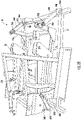
- the lift and recline mechanism 20 has at least one lift-recline actuator 22, shown in Figure 8 , and more preferably includes two lift-recline actuators 22, 24, with the first lift-recline actuator 22 being used to actuate the lift and recline functions of the lift and recline mechanism 20 and the second actuator 24 being a backrest actuator that can be used to separately adjust the positon of a back 32 of the chair 10 relative to the seat 30.
- the lift and recline chair mechanism 20 includes a lift-recline base 26 which forms a part of the lift and recline chair mechanism 20.
- the chair 10 includes the seat 30 and the back 32 connected to the lift and recline chair mechanism 20, for example, as shown in detail in Figures 9-18 .
- the back 32 is connected to the seat 30 so as to be effectively pivotable relative thereto. This can be done with a knife hinge 34 as shown in Figures 9-16 or via any other suitable connection. Arms are preferably connected to the seat portion of the chair. These are shown without upholstery in the drawings for clarity and the sake of explanation.
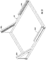
- the cradle assembly 40 includes a cradle base 42, preferably formed of welded tubular steel.
- Rear standoffs 44A, 44B are connected to the cradle base 42 and include aligned rear pivot axes 46A, 46B, preferably formed via pins.
- Front standoffs 48A, 48B are connected to the cradle base 42.
- the front standoffs 48A, 48B include aligned front pivot axes 50A, 50B, preferably also formed by pins.
- the front pivot axes 50A, 50B are located at a first distance H above the rear pivot axes 48A, 48B.
- the distance H is preferably at least about 7.5 cm (3 inches) and more preferably in the range of 15 cm to 20 cm (6 to 8 inches).
- an actuator mount 52 is connected to the cradle base 42, preferably along the rear portion thereof. This can be formed by a pair of plates that are spaced apart in order to allow pivotable mounting of a cradle actuator as discussed in detail below.
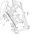
- front links 54A, 54B having first ends 56A, 56B are pivotably connected to respective ones of the front standoffs 48A, 48B. at the front pivot axes 50A, 50B.
- the second ends 58A, 58B of the front links 54A, 54B are pivotably connected to respective ones of front pivot connections 60A, 60B on the lift-recline base 26. These connections are preferably also formed via pins.
- Rear links 64A, 64B having first ends 66A, 66B are pivotably connected to respective ones of the rear standoffs, 44A, 44B at the rear pivot axes 46A, 46B.
- Second ends 68A, 68B of the rear link 64, 64B are pivotably connected to respective ones of rear pivot connections 70A, 70B on the lift-recline base.
- These rear pivot connections are preferably also formed via pins.
- the lift-recline base 26 includes rear uprights 28A, 28B, and the rear pivot connections 70A, 70B are located on the rear uprights, 28A, 28B.
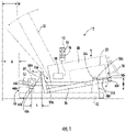
- the rear pivot connections, 70A, 70B on the rear uprights 28A, 28B are located above the front pivot connections 60A, 60B in a non-actuated position of the cradle assembly 40, as shown in Fig. 1A and can also be seen by comparing Figure 1A and 2 with Figures 1 and 3 .
- a cradle actuator 80 is connected between the actuator mount 52 and the lift-recline base 26.
- the connection with the actuator mount 52 is preferably a pinned connection in order to allow the actuator to be able to pivot during actuation based on the travel of the lift-recline base 26 relative to the cradle base 42.
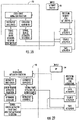
- a controller 90 shown schematically in Figure 1 , is provided that controls the movement of the cradle actuator 80 and the at least one lift-recline actuator 22, 24.
- the controller 90 preferably includes a processor and a fixed memory, such as a RAM or EPROM.
- the controller 90 is configured to actuate the cradle actuator 80 to move the lift-recline base 26 forward. In the lift and recliner chair 10, which is not covered by the current invention, this movement can be coordinated such that the movement of the lift-recline base 26 forward is done at the same time that the at least one lift-recline actuator 22, 24 is actuated to recline the back 32 to at least partially offset an extension distance A of the back 32 from the cradle base.
- the cradle assembly 40 provides an enhanced zero gravity mode with a full cradle position.
- the controller 90 is further configured to actuate the cradle actuator 80 to move the lift-recline base 26 forward as the at least one lift-recline actuator 22, 24 is actuated to raise the seat 30 to increase a vertical lift position of the seat 30 in comparison to a standard lift mode.
- Figure 15 provides the enhanced lift or straight lift mode.
- This preferably provides the vertical lift position of the seat being at least 5 cm (two inches) greater, and more preferably, at least 10 cm (four inches) greater than actuation of the cradle actuator 80 in the lift mode in which the lift-recline base 26 is moved forward in comparison to a maximum lift with the cradle actuator 80 in a non-actuated position.
- the controller 90 is configured to actuate the cradle actuator 80 to move the lift-recline base 26 forward to at least partially offset an extension distance A of the back 32 from the cradle base 26 as the backrest actuator 24 is actuated to recline the back 32.
- the controller 90 is preferably configured to actuate the cradle actuator 80 to move the lift-recline base 26 backward as the backrest actuator 24 is actuated to raise the back 32. This allows placement of the chair 10 with a smaller distance between the chair back 32 and the wall.
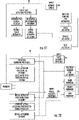
- the controller 90 is configured to specifically provide for or prevent certain combined actuator movements to prevent certain positions that could cause instability or comfort issues for the user.
- This can include one or more restrictions or simultaneous actuations of one or more of the lift-recline (or seat) actuator 22, backrest actuator 24, and the cradle actuator 80 as shown in Figs. 28-31 .
- one restriction by the controller 90 is that when the back is in a reclined position (backrest actuator 24 retracted) and the cradle actuator 80 is activated (extending to the cradle position), the controller 90 is configured to extend the backrest actuator 24 a distances equal to the movement of the cradle actuator 80.
- one restriction by the controller 90 is that when the chair is reclined (backrest actuator 24 retracted) and the cradle actuator 80 is extended, the controller 90 is configured such that when a user presses the up key or the manual up keys, the cradle actuator 80 is automatically retracted.
- one restriction by the controller 90 is that when the chair is in a reclined position using all three actuators and the up key is pressed, the controller 90 is configured such that all three actuators 22, 24, 80 reverse position and the chair lifts. This includes extending the backrest actuator 24 to raise the back, extending the seat actuator 22 to raise the seat, and retracting the cradle actuator 80 to lower the cradle assembly 40.
- one restriction by the controller 90 is that when the seat actuator 22 is in the lift position with the seat actuator 22 extended past neutral (neutral is considered a legs on the floor for an average user and the foot rest closed), the controller 90 is configures to disable the cradle actuator 80 so that it cannot move until the seat actuator 22 is back in the neutral position.
- the controller 90 can be configured to store favorite positions using programmable keys.
- the favorite position buttons activate all three actuators 22, 24, 80 simultaneously or is a pre-defined staged manner for comfort and are preferably restricted by one or more of the prior restrictions as shown in Figs. 28 - 31 in order to prevent unsafe operation or storage of an unsafe position.
- the actuators 22, 24, 80 are preferably electrically driven linear actuators
- the controller 90 can be configured to monitor a current draw of the separate lift-recline actuator 22, the backrest actuator 24, and the cradle actuator 80 to determine position, or separate position sensors can be used in connection with each of the actuators 22, 24, 80, such as Hall effect sensors, and the position information transmitted to the controller 90.
- Other types of encoders can also be used for sensing the actuator positions, if desired, depending on the particular actuators being used.
- the controller 90 can be programmed to operate no more than two of the three actuators at a same time to prevent current overloads and monitors the current draw of the actuators for this purpose. This allows the use of a smaller transformer in connection with powering the electric motor drives for the actuators 22, 24, 80.
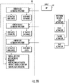
- a control device 92 is connected to the controller 90.
- the controller memory shown in Fig. 32 , is configured to store pre-set actuator positions for the at least one lift-recline actuator 22, 24 and the cradle actuator 80 that are activatable via the control device 92.
- the control device 92 preferably includes buttons 94 that are directional buttons for lift and recline movements as well as possibly backrest incline control.
- the control device 92 preferably further includes control buttons 96 for pre-set chair positions. These pre-set positions can be programmed into the controller memory, either in the factory or by a user, for example by pressing and holding a button 96 for a predetermined time period to "set" a favorite position in the memory, and then pressing the button 96 to recall the position.
- the controller 90 is preferably configured to provide a fully reclined and cradle position, as shown in Figure 16 in which the at least one lift-recline actuator 22, 24 is in a fully reclined position and the cradle actuator 80 is in a forward-most extended position.
- the lift and recliner chair 10 preferably includes an extendable foot rest 36 connected to the lift and recline mechanism 20. Preferably, this is connected to two pantograph linkages, 38A, 38B connected between the seat 30 and the foot rest 36. These are shown in detail in Figures 17 and 18 . While the pantograph linkages 38A, 38B are preferred, other mechanisms could be utilized, if desired.
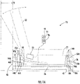
- FIGS 20 - 22 show a second lift and recliner chair 110, which is not covered by the current invention but described to aid the understanding of the invention.
- the lift and recliner chair 110 is similar to the lift and recliner chair 10, and like element numbers have been used to designate the same parts.
- the primary difference in the lift and recliner chair 110 is in that the cradle assembly 140 includes the rear standoffs 44A, 44B located along the back part of the cradle base 42, such that in the neutral position with the cradle actuator 80 retracted, the rear links 64A, 64B have the second ends 68A, 68B tilted forward to connect to the rear pivot axes 70A, 70B, and the front links 54A, 54B are also tilted forward from the first ends 56A, 56B to the second ends 58A, 58B, preferably by about 15° to 30°.
- the front pivot connections 60A, 60B to the lift-recline base 26 are arranged approximately 7.5 cm (3 inches) forward of the front pivot axes 50A, 50B, and the front standoffs 44A, 44B and the rear standoffs 48A, 48B (at the respective pivot axis locations) is about 50 cm to 55 cm (20 - 22 inches).
- the front links 54A, 54B arranged in this manner, the majority of the cradle movement is an upward movement at the front of the lift-recline base 26 and a combined forward and downward movement at the back of the lift-recline base 26.
- the extended position of lift-recline base 26 for the cradle actuator 80 being actuated (extended) is shown in phantom lines in Fig. 20 with the distance of forward travel E being indicated as well.
- the specific movement provided by the cradle assembly 140 can be tailored for specific requirements by adjusting the spacing and neutral angle positions of the front and rear links 54A, 54B; 64A, 64B, the spacing and height difference between the front pivot axes 50A, 50B and the rear pivot axes 46A, 46B, and the spacing and the height difference between the front pivot connections 60A, 60B; 70A, 70B.
- cradle assembly 40, 140 includes the front and rear links
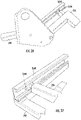
- functionality for the cradle movement can be provided with a cradle mechanism 240 using a track and roller or slide system having the desired configuration as shown in the third lift and recliner chair 210 as shown in Figs. 23 - 27 , which is also not covered by the current invention but described to aid the understanding of the invention.
- the cradle function is provided by slides or rollers (shown as rollers 252A, 252B; 254A, 254B) located on one of the cradle base 242 or the lift-recline base 226 (shown here on the lift-recline base 226) that interact with guide tracks 262A, 262B; 264A, 264B on the other of the lift-recline base 226 or the cradle base 242 (shown here on the cradle base 242) in order to provide a similar cradling movement when the cradle actuator is actuated to move the lift-recline base forward relative to the cradle base.
- slides or rollers shown as rollers 252A, 252B; 254A, 254B located on one of the cradle base 242 or the lift-recline base 226 (shown here on the lift-recline base 226) that interact with guide tracks 262A, 262B; 264A, 264B on the other of the
- the guide tracks 262A, 262B; 264A, 264B are preferably linear, but could be curved.
- the guide tracks 262A, 262B; 264A, 264B preferably have a generally C-shaped cross-section.
- the front guide tracks 262A, 262B are angled upwardly as they extend toward the front of the chair 210 by an angle of about 30° to 60°, and more preferably of between 35° and 45°.
- the rear guide tracks 264A, 264B are preferably horizontal.
- the guide tracks 262A, 262B; 264A, 264B are preferably permanently attached to the cradle base 242, preferably by welding.
- rollers 252A, 252B; 254A, 254B are shown, these could be replaced with solid material slides that are adapted to an interior shape of the guide tracks 262A, 262B; 264A, 264B.
- the slides could be made of a polymeric material or a metal base coated with a polymeric material, such as nylon.
- the cradle actuator 280 can move the lift-recline base 226 between a neutral position, shown in Fig. 24 , and an extended, cradle position, shown in Fig. 25 , and this motion is translated to the lift-recline base 226 which supports a separate lift and recline chair mechanism 220, that can include a lift-recline actuator 222 as well as optionally a separate backrest actuator (not shown).
- a lift-recline actuator 222 as well as optionally a separate backrest actuator (not shown).
- This provides the same functionality for the chair as the prior arrangements 10, 110 without the need for the pivoting link connections.
- the exact cradle path can be customized based on the path of the guide tracks 262A, 262B; 264A, 264B.
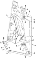
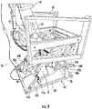
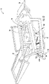
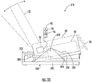
- Figure 33 shows an embodiment of a lift and recliner chair 310 in accordance with the current invention.
- the lift and recliner chair 310 is similar to the lift and recliner chair 10, and like element numbers have been used to designate the same parts.
- the primary difference in the lift and recliner chair 310 is in that the cradle assembly 340 includes a cradle base 342 having generally centrally located standoffs 344 on each side, and the lift-recline base 326 also includes generally centrally located uprights 328 on each side, which are connected along aligned pivot axes 370.
- the chair 310 includes the seat 30 and the back 32 connected to the lift and recline chair mechanism 20, and the lift and recline chair mechanism 20 includes the lift-recline base 326 which forms a part of the lift and recline chair mechanism 20.
- the cradle base 342 is also preferably formed of welded tubular steel and the standoffs 344 are connected to the cradle base 342 and include the aligned pivot axes 370, with pivot connections preferably formed via pins that extend through holes in the standoffs 344 and the uprights 328 at the pivot axes 370.
- An actuator mount 352 is connected to the cradle base 342, preferably along the rear portion thereof. This can be formed by a pair of plates that are spaced apart in order to allow pivotable mounting of the cradle actuator 380.
- the opposite end of the cradle actuator 380 is preferably connected to a medial cross piece that extends between the two sides of the lift-recline base 326, The cradle actuator 380 is actuated via the controller 90 to move the lift-recline base 326 in an arcuate path about the pivot axes 370 to move the lift-recline base 326 forward and upward in a cradle motion from its initial neutral position to an extended, cradle position.
- This arrangement provides for the same superposed types of motion in combination with lift and recline chair mechanism 20 as the lift and recliner chairs 10, 110, 210. Adjusting the height and front-to-back location of the pivot axes 370 can be used to achieve different cradle motion paths.
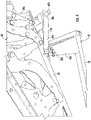
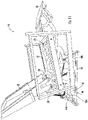
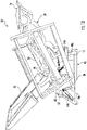
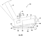
- Figure 34 shows a second embodiment of a lift and recliner chair 410 in accordance with the current invention.
- the lift and recliner chair 410 is similar to the lift and recliner chair 310, and like element numbers have been used to designate the same parts.
- the primary difference in the lift and recliner chair 410 is in that the cradle assembly 440 includes a cradle base 442 having rear standoffs 444 on each side, and the lift-recline base 426 is connected along aligned pivot axes 470 to the rear standoffs 444.
- the chair 410 includes the seat 30 and the back 32 connected to the lift and recline chair mechanism 20, and the lift and recline chair mechanism 20 includes the lift-recline base 426 which forms a part of the lift and recline chair mechanism 20.
- the cradle base 442 is also preferably formed of welded tubular steel and the rear standoffs 444 are connected to the cradle base 442 and include the aligned pivot axes 470, with pivot connections preferably formed via pins that extend through holes in the standoffs 444 and the lift-recline base 426 at the pivot axes 470.
- the cradle actuator 480 is connected to the cradle base 442, and is preferably constrained to a linear horizontal actuation drive motion.
- the opposite end of the cradle actuator 480 is preferably connected pivotally to a drive link 482 that extends to a pivot point 460 on the lift-recline base 426, preferably near the front thereof.
- the cradle actuator 480 is actuated via the controller 90 to move the lift-recline base 426 in an arcuate path about the pivot axes 470 to move the lift-recline base 326 upward at the front in a cradle motion from its initial neutral position to an extended, cradle position, as shown.
- This arrangement provides for the same superposed types of motion in combination with lift and recline chair mechanism 20 as the lift and recliner chairs 10, 110, 210, 310.
- pivotal connections referred to in the above embodiments can be formed by bolts or pins, with or without bushings to prevent wear, or any other type of suitable pivotable connection.
- the lift and recline chair mechanism 20 could just be a recline mechanism of the type known to those of ordinary skill in the art and have a recline base instead of a lift-recline base. This would provide recliner chairs with the additional advantages of the cradle assembly movements.
- a recliner chair comprising: a recline chair mechanism providing a reclining movement, the recline chair mechanism having a recline base; a seat and a back connected to the recline chair mechanism, with the back being effectively connected relative to the seat; a cradle assembly, including: a cradle base; standoffs on the cradle base with aligned pivot axes; the recline base being pivotably connected to the standoffs at the aligned pivot axes; an actuator mount connected to the cradle base; a cradle actuator connected between the actuator mount on the cradle base and the recline base; and a controller that controls movement of the cradle actuator.
- the standoffs on the cradle base can be generally centrally located, and the recline base also includes generally centrally located uprights on each side, and the recline base is connected to the standoffs at the uprights via pins extending along the pivot axes.
- the recline chair mechanism may incude a recline actuator, and the controller may be configured to actuate the cradle actuator to move the recline base forward as the recline actuator is actuated to recline the back to at least partially offset an extension distance of the back from the cradle base.
- the standoffs on the cradle base can be rear standoffs, and the recline base may be connected to the rear standoffs via pins extending along the pivot axes.
- the controller may comprise a processor and a controller memory, a control device may be connected to the controller, and the controller memory is configured to store pre-set actuator positions for at least one recline actuator of the recline chair mechanism, and the cradle actuator that are activatable via the control device.
- the controller may be configured to provide a fully reclined and cradle position in which at least one recline actuator is in a fully reclined position and the cradle actuator is in a forward-most extended position.
- the current invention provides a lift and recliner chair, comprising: a lift and recline chair mechanism having at least one lift-recline actuator that controls a lifting movement and a reclining movement, the lift and recline chair mechanism having a lift-recline base; a seat and a back connected to the recline chair mechanism, with the back being effectively connected relative to the seat; a cradle assembly, including: a cradle base; standoffs on the cradle base with aligned pivot axes; the lift-recline base being pivotably connected to the standoffs at the aligned pivot axes; an actuator mount connected to the cradle base; a cradle actuator connected between the actuator mount on the cradle base and the lift-recline base; and a controller that controls movement of the cradle actuator.
- the standoffs on the cradle base can be generally centrally located, and the lift-recline base also includes generally centrally located uprights on each side, and the lift-recline base is connected to the standoffs at the uprights via pins extending along the pivot axes.
- the controller may be configured to actuate the cradle actuator to move the lift-recline base forward as the at least one lift-recline actuator is actuated to recline the back to at least partially offset an extension distance of the back from the cradle base.
- the standoffs on the cradle base can be rear standoffs, and the lift-recline base may be connected to the rear standoffs via pins extending along the pivot axes.
- the controller may comprise a processor and a controller memory, a control device is connected to the controller, and the controller memory may be configured to store pre-set actuator positions for the at least one lift-recline actuator and the cradle actuator that are activatable via the control device.
- the controller can be configured to provide a fully reclined and cradle position in which at least one loft-recline actuator is in a fully reclined position and the cradle actuator is in a forward-most extended position.
Applications Claiming Priority (3)
| Application Number | Priority Date | Filing Date | Title |
|---|---|---|---|
| US201762457259P | 2017-02-10 | 2017-02-10 | |
| EP18750590.4A EP3544468B1 (fr) | 2017-02-10 | 2018-02-06 | Fauteuil inclinable ou fauteuil basculeur et inclinable à profil d'élévation variable |
| PCT/US2018/016961 WO2018148167A1 (fr) | 2017-02-10 | 2018-02-06 | Fauteuil inclinable ou fauteuil basculeur et inclinable à profil d'élévation variable |
Related Parent Applications (1)
| Application Number | Title | Priority Date | Filing Date |
|---|---|---|---|
| EP18750590.4A Division EP3544468B1 (fr) | 2017-02-10 | 2018-02-06 | Fauteuil inclinable ou fauteuil basculeur et inclinable à profil d'élévation variable |
Publications (1)
| Publication Number | Publication Date |
|---|---|
| EP3987979A1 true EP3987979A1 (fr) | 2022-04-27 |
Family
ID=63106535
Family Applications (2)
| Application Number | Title | Priority Date | Filing Date |
|---|---|---|---|
| EP21213196.5A Pending EP3987979A1 (fr) | 2017-02-10 | 2018-02-06 | Fauteuil inclinable ou fauteuil basculeur et inclinable à profil d'élévation variable |
| EP18750590.4A Active EP3544468B1 (fr) | 2017-02-10 | 2018-02-06 | Fauteuil inclinable ou fauteuil basculeur et inclinable à profil d'élévation variable |
Family Applications After (1)
| Application Number | Title | Priority Date | Filing Date |
|---|---|---|---|
| EP18750590.4A Active EP3544468B1 (fr) | 2017-02-10 | 2018-02-06 | Fauteuil inclinable ou fauteuil basculeur et inclinable à profil d'élévation variable |
Country Status (6)
| Country | Link |
|---|---|
| US (4) | US10327553B2 (fr) |
| EP (2) | EP3987979A1 (fr) |
| CN (2) | CN110290728B (fr) |
| CA (1) | CA3048915A1 (fr) |
| PL (1) | PL3544468T3 (fr) |
| WO (1) | WO2018148167A1 (fr) |
Families Citing this family (18)
| Publication number | Priority date | Publication date | Assignee | Title |
|---|---|---|---|---|
| US20230210704A1 (en) * | 2014-07-14 | 2023-07-06 | Exokinetics, Inc. | Lifting mechanism and chanirs |
| US9986835B2 (en) | 2016-09-22 | 2018-06-05 | La-Z-Boy Incorporated | Furniture member having cam tilt mechanism |
| CN110290728B (zh) * | 2017-02-10 | 2023-12-19 | 高登科技公司 | 躺椅或具有可变升降姿态的升降躺椅 |
| CN106724260B (zh) * | 2017-03-20 | 2023-11-07 | 泰州市瑞美机械有限公司 | 一种具有高强度和高稳定性的椅架 |
| US10537178B2 (en) | 2017-04-07 | 2020-01-21 | La-Z-Boy Incorporated | Furniture member having flexible seatback |
| US11241093B2 (en) * | 2017-04-19 | 2022-02-08 | Denis Viger | Zero gravity chair mechanism |
| US10829222B2 (en) * | 2017-11-20 | 2020-11-10 | B/E Aerospace, Inc. | Aircraft passenger seat with zero-g taxi, take-off and landing recline position |
| US10820708B2 (en) | 2018-05-18 | 2020-11-03 | La-Z-Boy Incorporated | Furniture member with wall-proximity mechanism and locking trigger |
| CN116982815A (zh) * | 2018-11-02 | 2023-11-03 | 常州泽辉机械有限公司 | 助站式躺椅用铁架的工作方法 |
| DE202019100213U1 (de) * | 2019-01-15 | 2019-01-31 | Ciar S.P.A. | Sessel |
| US11134778B2 (en) | 2019-05-09 | 2021-10-05 | La-Z-Boy Incorporated | Reclining chaise |
| US11140990B2 (en) * | 2020-01-17 | 2021-10-12 | Haining My Home Mechanism Co., Ltd. | Chair support structure and chair having the same |
| JP7009535B2 (ja) * | 2020-03-16 | 2022-02-10 | 本田技研工業株式会社 | 乗り物及び乗り物の制御方法 |
| DE102020107243B4 (de) * | 2020-03-17 | 2024-02-08 | Ciar S.P.A. | Sitz- und Liegemöbel und Verfahren zum Verstellen eines Sitz- und Liegemöbels |
| US11197549B1 (en) | 2020-09-28 | 2021-12-14 | La-Z-Boy Incorporated | Wall-proximity furniture member having sync mechanism |
| EP4070632A1 (fr) | 2021-02-11 | 2022-10-12 | Google LLC | Joint d'étanchéité léger à distribution de force transversale |
| US20220400863A1 (en) * | 2021-06-18 | 2022-12-22 | Ultra-Mek, Inc | Reclining seating unit with reciprocating capability |
| WO2024020291A1 (fr) * | 2022-07-21 | 2024-01-25 | Ultra-Mek, Inc. | Chaise inclinable avec action de basculement pour position de repos cardiaque |
Citations (8)
| Publication number | Priority date | Publication date | Assignee | Title |
|---|---|---|---|---|
| US3235304A (en) * | 1964-06-03 | 1966-02-15 | Henry P Glass | Adjustable reclining chair |
| US5312153A (en) | 1990-07-23 | 1994-05-17 | Ortho-Kinetics, Inc. | Recline lift wall hugger chair |
| US5765913A (en) | 1995-10-18 | 1998-06-16 | La-Z-Boy Incorporated | Glider chair |
| US20010035668A1 (en) | 1999-05-06 | 2001-11-01 | Edward J. Gaffney | Power actuated reclining chair with wall-hugger function |
| KR200379986Y1 (ko) * | 2004-12-27 | 2005-03-28 | 조미자 | 허리운동용 의자 |
| US8308228B2 (en) | 2010-02-11 | 2012-11-13 | L & P Property Management Company | Zero-wall clearance linkage mechanism for a lifting recliner |
| US9016788B1 (en) | 2004-09-13 | 2015-04-28 | Golden Technologies, Inc. | Lift chair and recliner |
| US9326606B2 (en) * | 2013-09-19 | 2016-05-03 | La-Z-Boy Incorporated | Furniture member power mechanism with zero gravity and rear tilt positions |
Family Cites Families (31)
| Publication number | Priority date | Publication date | Assignee | Title |
|---|---|---|---|---|
| US4007960A (en) * | 1975-04-30 | 1977-02-15 | Gaffney Edward J | Reclining elevator chair |
| US4306746A (en) * | 1979-06-21 | 1981-12-22 | Leggett & Platt, Incorporated | All linkage close-to-the-wall reclining chair |
| US5072988A (en) * | 1987-06-09 | 1991-12-17 | Super Sagless Corporation | Wall proximity chair |
| US4852939A (en) * | 1987-10-23 | 1989-08-01 | Orthokinetics, Inc. | Device for converting a recliner chair to a recliner-lift chair |
| US20020063459A1 (en) * | 1999-05-06 | 2002-05-30 | Edward J. Gaffney | Power actuated reclining chair with wall-hugger function |
| US6213554B1 (en) * | 1999-09-07 | 2001-04-10 | Groupe Myca | Lift chair |
| DE19944114C2 (de) * | 1999-09-15 | 2002-11-28 | Bert Lieber | Einrichtungsgegenstand |
| JP2001305175A (ja) | 2000-04-27 | 2001-10-31 | Asmo Co Ltd | モータにおける巻線の断線検出装置 |
| US6604791B1 (en) | 2002-04-05 | 2003-08-12 | Hsin Hao Health Materials Co., Ltd. | Reclining leisure chair |
| GB0325358D0 (en) * | 2003-10-30 | 2003-12-03 | Peter Cook Internat Plc | Powered furniture |
| WO2006023447A2 (fr) * | 2004-08-16 | 2006-03-02 | Hill-Rom Services, Inc. | Fauteuil |
| US7090297B2 (en) * | 2004-10-13 | 2006-08-15 | La-Z-Boy Incorporated | Heavy lift chair |
| US7455360B2 (en) * | 2006-04-21 | 2008-11-25 | L & P Property Management | Seating furniture with lift mechanism |
| US7445279B2 (en) | 2006-11-13 | 2008-11-04 | L & P Property Management Company | Pivot-over-arm reclining mechanism for a seating unit |
| US7766421B2 (en) * | 2006-12-21 | 2010-08-03 | L & P Property Management Company | Recliner lift chair with power lift and reclining units |
| US9241571B2 (en) * | 2009-08-18 | 2016-01-26 | Integrated Furniture Technologies Limited | Adjustable furniture |
| US8419122B2 (en) * | 2010-01-25 | 2013-04-16 | L & P Property Management Company | Zero-wall clearance linkage mechanism for a high-leg seating unit |
| US8915544B2 (en) | 2011-08-26 | 2014-12-23 | La-Z-Boy Incorporated | Furniture member with mechanism for powered occupant lift |
| US8727433B2 (en) | 2012-01-05 | 2014-05-20 | L & P Property Management Company | Zero-wall clearance linkage mechanism for a lifting recliner |
| CN202723157U (zh) * | 2012-06-06 | 2013-02-13 | 厦门纬嘉运动器材有限公司 | 床椅 |
| EP2983944B1 (fr) | 2013-04-08 | 2018-04-04 | B/E Aerospace, Inc. | Siège d'aéronef employant deux actionneurs de translation de siège et d'inclinaison de siège |
| CA2912194A1 (fr) * | 2013-05-10 | 2014-11-13 | L & P Property Management Company | Mecanisme de liaison pour unite d'assise a haut pied |
| US9010851B2 (en) * | 2013-09-19 | 2015-04-21 | La-Z-Boy Incorporated | Furniture member power mechanism with selectable lift movement and zero gravity position |
| US9468295B2 (en) * | 2014-04-04 | 2016-10-18 | L & P Property Management Company | Zero-wall clearance linkage mechanism for a dual motor lifting recliner |
| US9277822B1 (en) * | 2014-09-02 | 2016-03-08 | La-Z-Boy Incorporated | Furniture member with powered mechanism providing lift and zero gravity positions |
| US9332844B2 (en) * | 2014-10-08 | 2016-05-10 | Aminach Bedding & Furniture Manufacturing Ltd. | Electrically controlled recliner with independent rocker-limiting mechanism |
| US9603452B2 (en) * | 2014-10-14 | 2017-03-28 | Ultra-Mek, Inc. | Gliding-reclining seating unit with power actuators |
| EP3023329B1 (fr) | 2014-11-20 | 2017-12-20 | Optimares S.p.A. | Système de déplacement d'un siège, notamment un siège d'avion |
| CN104720397B (zh) * | 2015-01-16 | 2018-04-27 | 浙江工业大学 | 分动式沙发椅 |
| US9795528B1 (en) * | 2015-11-05 | 2017-10-24 | Images Of America, Inc. | Bariatric lift chair |
| CN110290728B (zh) * | 2017-02-10 | 2023-12-19 | 高登科技公司 | 躺椅或具有可变升降姿态的升降躺椅 |
-
2018
- 2018-02-06 CN CN201880011532.1A patent/CN110290728B/zh active Active
- 2018-02-06 CA CA3048915A patent/CA3048915A1/fr active Pending
- 2018-02-06 EP EP21213196.5A patent/EP3987979A1/fr active Pending
- 2018-02-06 PL PL18750590T patent/PL3544468T3/pl unknown
- 2018-02-06 EP EP18750590.4A patent/EP3544468B1/fr active Active
- 2018-02-06 CN CN202311655855.3A patent/CN117678866A/zh active Pending
- 2018-02-06 WO PCT/US2018/016961 patent/WO2018148167A1/fr active Search and Examination
- 2018-02-09 US US15/892,840 patent/US10327553B2/en active Active
-
2019
- 2019-05-13 US US16/410,222 patent/US10813457B2/en active Active
-
2020
- 2020-10-26 US US17/079,683 patent/US11122898B2/en active Active
-
2021
- 2021-03-12 US US17/199,695 patent/US11412853B2/en active Active
Patent Citations (8)
| Publication number | Priority date | Publication date | Assignee | Title |
|---|---|---|---|---|
| US3235304A (en) * | 1964-06-03 | 1966-02-15 | Henry P Glass | Adjustable reclining chair |
| US5312153A (en) | 1990-07-23 | 1994-05-17 | Ortho-Kinetics, Inc. | Recline lift wall hugger chair |
| US5765913A (en) | 1995-10-18 | 1998-06-16 | La-Z-Boy Incorporated | Glider chair |
| US20010035668A1 (en) | 1999-05-06 | 2001-11-01 | Edward J. Gaffney | Power actuated reclining chair with wall-hugger function |
| US9016788B1 (en) | 2004-09-13 | 2015-04-28 | Golden Technologies, Inc. | Lift chair and recliner |
| KR200379986Y1 (ko) * | 2004-12-27 | 2005-03-28 | 조미자 | 허리운동용 의자 |
| US8308228B2 (en) | 2010-02-11 | 2012-11-13 | L & P Property Management Company | Zero-wall clearance linkage mechanism for a lifting recliner |
| US9326606B2 (en) * | 2013-09-19 | 2016-05-03 | La-Z-Boy Incorporated | Furniture member power mechanism with zero gravity and rear tilt positions |
Also Published As
| Publication number | Publication date |
|---|---|
| US10327553B2 (en) | 2019-06-25 |
| EP3544468B1 (fr) | 2022-01-05 |
| CN117678866A (zh) | 2024-03-12 |
| US20180228290A1 (en) | 2018-08-16 |
| CN110290728B (zh) | 2023-12-19 |
| US11122898B2 (en) | 2021-09-21 |
| WO2018148167A1 (fr) | 2018-08-16 |
| US20210037976A1 (en) | 2021-02-11 |
| CN110290728A (zh) | 2019-09-27 |
| PL3544468T3 (pl) | 2022-05-02 |
| CA3048915A1 (fr) | 2018-08-16 |
| US10813457B2 (en) | 2020-10-27 |
| US11412853B2 (en) | 2022-08-16 |
| EP3544468A4 (fr) | 2020-09-16 |
| US20210196046A1 (en) | 2021-07-01 |
| US20190261776A1 (en) | 2019-08-29 |
| EP3544468A1 (fr) | 2019-10-02 |
Similar Documents
| Publication | Publication Date | Title |
|---|---|---|
| EP3544468B1 (fr) | Fauteuil inclinable ou fauteuil basculeur et inclinable à profil d'élévation variable | |
| US9326608B1 (en) | Multi-configurable seating device | |
| US8973997B2 (en) | Seat structure with sit-to-stand feature | |
| CA2943046C (fr) | Mecanisme de liaison sans degagement de paroi pour fauteuil inclinable elevateur dote de deux moteurs | |
| US7543885B2 (en) | Lift chair and recliner | |
| US8944498B2 (en) | Linkage mechanism for a dual-motor lifting recliner | |
| CN107072396B (zh) | 具有提供提升和零重力位置的动力机构的家具构件 | |
| US20110121626A1 (en) | Lift chair | |
| US10729246B2 (en) | Person support apparatus with shear-reducing pivot assembly | |
| JP4923605B2 (ja) | 電動車椅子 | |
| GB2526802A (en) | Seat recline mechanism, adjustable seating assembly, and method | |
| KR101920805B1 (ko) | 기립 보조 의자 | |
| JP2012040200A (ja) | 立ち上がり補助装置 | |
| KR20210037237A (ko) | 기립보조의자 | |
| KR20180038176A (ko) | 기립 보조 의자 | |
| JP2024019000A (ja) | 車いすの制御方法 | |
| JP2002136377A (ja) | 座椅子 | |
| GB2326823A (en) | Elevating seat |
Legal Events
| Date | Code | Title | Description |
|---|---|---|---|
| PUAI | Public reference made under article 153(3) epc to a published international application that has entered the european phase |
Free format text: ORIGINAL CODE: 0009012 |
|
| STAA | Information on the status of an ep patent application or granted ep patent |
Free format text: STATUS: THE APPLICATION HAS BEEN PUBLISHED |
|
| AC | Divisional application: reference to earlier application |
Ref document number: 3544468 Country of ref document: EP Kind code of ref document: P |
|
| AK | Designated contracting states |
Kind code of ref document: A1 Designated state(s): AL AT BE BG CH CY CZ DE DK EE ES FI FR GB GR HR HU IE IS IT LI LT LU LV MC MK MT NL NO PL PT RO RS SE SI SK SM TR |
|
| STAA | Information on the status of an ep patent application or granted ep patent |
Free format text: STATUS: REQUEST FOR EXAMINATION WAS MADE |
|
| 17P | Request for examination filed |
Effective date: 20221020 |
|
| RBV | Designated contracting states (corrected) |
Designated state(s): AL AT BE BG CH CY CZ DE DK EE ES FI FR GB GR HR HU IE IS IT LI LT LU LV MC MK MT NL NO PL PT RO RS SE SI SK SM TR |
|
| STAA | Information on the status of an ep patent application or granted ep patent |
Free format text: STATUS: EXAMINATION IS IN PROGRESS |
|
| 17Q | First examination report despatched |
Effective date: 20230921 |