EP3987689B1 - Verfahren, vorrichtung und maschinenlesbare medien für die drahtlose kommunikation in kommunikationsnetzwerken - Google Patents
Verfahren, vorrichtung und maschinenlesbare medien für die drahtlose kommunikation in kommunikationsnetzwerken Download PDFInfo
- Publication number
- EP3987689B1 EP3987689B1 EP19734039.1A EP19734039A EP3987689B1 EP 3987689 B1 EP3987689 B1 EP 3987689B1 EP 19734039 A EP19734039 A EP 19734039A EP 3987689 B1 EP3987689 B1 EP 3987689B1
- Authority
- EP
- European Patent Office
- Prior art keywords
- wireless device
- wireless
- communication
- link
- enabled
- Prior art date
- Legal status (The legal status is an assumption and is not a legal conclusion. Google has not performed a legal analysis and makes no representation as to the accuracy of the status listed.)
- Active
Links
Images


Classifications
-
- H—ELECTRICITY
- H04—ELECTRIC COMMUNICATION TECHNIQUE
- H04B—TRANSMISSION
- H04B10/00—Transmission systems employing electromagnetic waves other than radio-waves, e.g. infrared, visible or ultraviolet light, or employing corpuscular radiation, e.g. quantum communication
- H04B10/11—Arrangements specific to free-space transmission, i.e. transmission through air or vacuum
- H04B10/114—Indoor or close-range type systems
- H04B10/116—Visible light communication
-
- H—ELECTRICITY
- H04—ELECTRIC COMMUNICATION TECHNIQUE
- H04B—TRANSMISSION
- H04B10/00—Transmission systems employing electromagnetic waves other than radio-waves, e.g. infrared, visible or ultraviolet light, or employing corpuscular radiation, e.g. quantum communication
- H04B10/07—Arrangements for monitoring or testing transmission systems; Arrangements for fault measurement of transmission systems
- H04B10/075—Arrangements for monitoring or testing transmission systems; Arrangements for fault measurement of transmission systems using an in-service signal
- H04B10/079—Arrangements for monitoring or testing transmission systems; Arrangements for fault measurement of transmission systems using an in-service signal using measurements of the data signal
- H04B10/0795—Performance monitoring; Measurement of transmission parameters
-
- H—ELECTRICITY
- H04—ELECTRIC COMMUNICATION TECHNIQUE
- H04B—TRANSMISSION
- H04B10/00—Transmission systems employing electromagnetic waves other than radio-waves, e.g. infrared, visible or ultraviolet light, or employing corpuscular radiation, e.g. quantum communication
- H04B10/11—Arrangements specific to free-space transmission, i.e. transmission through air or vacuum
- H04B10/114—Indoor or close-range type systems
-
- H—ELECTRICITY
- H04—ELECTRIC COMMUNICATION TECHNIQUE
- H04W—WIRELESS COMMUNICATION NETWORKS
- H04W76/00—Connection management
- H04W76/10—Connection setup
- H04W76/14—Direct-mode setup
-
- H—ELECTRICITY
- H04—ELECTRIC COMMUNICATION TECHNIQUE
- H04W—WIRELESS COMMUNICATION NETWORKS
- H04W88/00—Devices specially adapted for wireless communication networks, e.g. terminals, base stations or access point devices
- H04W88/02—Terminal devices
- H04W88/04—Terminal devices adapted for relaying to or from another terminal or user
Definitions
- Embodiments of the disclosure relate to wireless communication in communication networks, and particularly relate to methods, apparatus and machine-readable mediums for wireless communication in communication networks enabled for wireless light communication.
- LC Wireless Light Communication
- OBC Optical Wireless Communication
- VLC Visible Light Communication
- LiFi Low-Fi
- LC has certain characteristics that may be considered desirable for certain cellular communication networks.
- LC has the potential to provide very high data communication rates that are comparable to or potentially higher than anticipated radio-based 5G capabilities.
- deploying LC networks may in some ways be less complicated than deploying radio-based networks.
- wireless LC links rely predominantly on line-of-sight (LoS) components to achieve adequate signal-to-noise ratio.
- LoS line-of-sight
- a wireless LC link provided between an LC-enabled wireless device and an LC-enabled access point may therefore be disrupted when a LoS communication path between these LC-enabled nodes is blocked. Identifying strategies for dealing with such disruptions may facilitate adoption of wireless LC technology for communication.
- US 10165483 B1 discloses a method of mitigating interference in distributed antenna systems (DAS), which includes determining, at a processing node of the DAS, that a first wireless device attached to a first access node is within a coverage area of one or more antennae of the DAS, and transmitting, from the processing node to the first access node, a request to trigger a handover of the first wireless device from the first access node to the DAS.
- DAS distributed antenna systems
- CN 104202088 A discloses a visible light communication method which involves at least two forwarding facilities used as relays between visible light communication facilities under non-line-of-sight transmission conditions.
- CN 106656326 B discloses a control method for assisting relay selection by using visible light positioning in a wireless local area network, wherein the wireless local area network includes a light source.
- the control method uses visible light positioning to establish a set of associated user terminals as a relay node of a target user.
- a method performed in a node of a communication network.
- the method enables data communication to be established between a first wireless device and the communication network upon a wireless Light Communication, LC, link between the first wireless device and an LC-enabled Access Point, AP, of the communication network becoming unavailable.
- the method comprises: identifying a second wireless device for relaying data between the first wireless device and the communication network via a first communication link between the first wireless device and the second wireless device and a second communication link between the second wireless device and an AP of the communication network associated with the second wireless device.
- Data communication via at least one of: the first communication link and the second communication link is enabled by wireless Radio-Frequency, RF, communication.
- a non-transitory machine-readable medium storing instructions for execution by processing circuitry of a node of a communication network is provided, the instructions being configured to cause the processing circuitry to implement the method (and other methods set out herein).
- a non-transitory machine-readable medium storing instructions for execution by processing circuitry of a node of a communication network, to enable data communication to be established between a first wireless device and the communication network upon a wireless Light Communication, LC, link between the first wireless device and an LC-enabled Access Point, AP, of the communication network becoming unavailable.
- Execution of the instructions by the processing circuitry cause the node to: identify a second wireless device for relaying data between the first wireless device and the communication network via a first communication link between the first wireless device and the second wireless device and a second communication link between the second wireless device and an AP of the communication network associated with the second wireless device.
- Data communication via at least one of: the first communication link and the second communication link is enabled by wireless Radio-Frequency, RF, communication.
- a node configured to implement the method (and other methods set out herein).
- a node for enabling data communication to be established between a first wireless device and a communication network upon a wireless Light Communication, LC, link between the first wireless device and an LC-enabled Access Point, AP, of the communication network becoming unavailable.
- LC wireless Light Communication
- AP LC-enabled Access Point
- the node comprises processing circuitry and a non-transitory machine-readable medium, the non-transitory machine-readable medium storing instructions which, when executed by the processing circuitry, cause the node to: identify a second wireless device for relaying data between the first wireless device and the communication network via a first communication link between the first wireless device and the second wireless device and a second communication link between the second wireless device and an AP of the communication network associated with the second wireless device.
- Data communication via at least one of: the first communication link and the second communication link is enabled by wireless Radio-Frequency, RF, communication.
- LC Light Communication
- OBC optical wireless communication
- VLC visible light communication
- LiFi Low-Fi
- the main concept behind LC is to communicate binary data using rapidly varying levels of light intensity.
- one or multiple light emitting diodes (LEDs) are deployed in an LC-enabled transmitting device in order to modulate binary data in different levels of emitted light intensity.
- the deployed LEDs change the levels of the emitted light intensity at rates that may not be perceivable by the human eye.
- An LC-enabled receiving device detects the changes of the emitted light intensity using one or more photo detectors (PDs), for example. In this way, the receiving device is able to detect the transmitted data.
- PDs photo detectors
- Some LC signals may have a wavelength which is in the visible part of the spectrum, although some LC signals may additionally or alternatively have a wavelength that is non-visible (e.g., infrared or ultraviolet).
- the light generated by the transmitting device is subject to modulation with one or more data sources, such that the intensity of the light varies over time in a manner which can be detected and decoded by the receiving device.
- a wireless LC link is dominated by a Line-of Sight (LoS) component between a transmitting device and a receiving device.
- LoS Line-of Sight
- SINR Signal to Interference plus Noise Ratio
- Such scenarios may include, for example, a blockage in the LoS communication path between LC-enabled nodes of a communication network, constraints in terms of the LC signalling range of LC-enabled nodes, a signal metric of the wireless LC link being unable to meet one or more criteria, or an error occurring in the transmission of messages between nodes of the communication network.
- embodiments described herein may provide access to a communication network so that data communication can be established.
- One or more technical benefits may be realised by embodiments of this disclosure. Such benefits may include, among others, reliable and/or robust data communication, distribution of network capacity across a communication network, more efficient utilisation and/or preservation of network resources, improved quality of data communication, and/or efficient energy usage across a communication network.
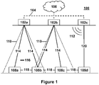
- Figure 1 is a schematic diagram showing a communication network 100 according to embodiments of the disclosure.
- the illustration shows an example where the network 100 is deployed indoors (with the floor at the bottom of the page and the ceiling at the top); however, those skilled in the art will appreciate that the concepts disclosed herein are applicable to indoor and outdoor environments and the nodes of the communication network 100 are not limited to their locations depicted in the illustration.
- the network 100 comprises a plurality of nodes which include a plurality of Access Points (APs) 102a, 102b, 102c (collectively, 102) communicatively coupled via a backhaul connection 104 to another node of the network 100 which, in this example, comprises a network node 106, which itself may comprise or be communicatively coupled to a host computer, for example.
- APs Access Points
- the network 100 may comprise one or more APs 102.
- At least part of the backhaul connection 104 may be provided by a wired connection, such as an Ethernet connection (e.g., power over Ethernet) or other packet data connection. Additionally or alternatively, at least part of the backhaul connection 104 may be provided by a wireless connection.
- the plurality of nodes of the network 100 further include a plurality of wireless devices 108a, 108b, 108c, 108d (collectively, 108) that can be communicatively coupled to the network node 106 via one or more of the APs 102. Although four wireless devices 108 are depicted in the illustration, the network 100 may comprise one or more wireless devices 108.
- the wireless devices 108 may alternatively be termed a user equipment (UE) or a mobile station (STA). As will be explained in more detail below, some embodiments utilize at least two wireless devices 108.
- the APs 102 are configured to provide wireless access to the communication network 100 using one or both of wireless RF communication and wireless LC to provide a wireless communication link between a wireless device 108 and a corresponding AP 102.
- two of the APs 102a, 102b are configured to provide respective wireless LC cells 110 that serve the wireless devices (in this case, wireless devices 108a, 108b, 108c) located within these two LC cells 110.
- An AP 102 that is capable of providing such a wireless LC cell 110 may be referred to as an "LC-enabled AP".
- the other AP 102c is configured to provide a wireless RF cell or coverage area using a wireless RF signal 112.
- the AP 102c may provide access to the communication network 100 for any of the wireless devices 108 within RF signalling range of the AP 102c.
- the wireless device 108d that is not located within a wireless LC cell 110 may access the communication network via the AP 102c using wireless RF communication.
- An AP 102 that is capable of providing access to the communication network 100 using wireless RF communication may be referred to as an "RF-enabled AP".
- An RF-enabled AP may provide an additional or alternative access mechanism to the communication network 100 if a wireless device 108 is unable to access the communication network 100 via an LC-enabled AP 102.
- wireless LC links 114 are provided between the LC-enabled APs 102a, 102b and each of the corresponding wireless devices 108a, 108b, 108c served by the two LC cells 110.
- a blockage 116 may interrupt a Line-of-Sight (LoS) communication path between an AP 102 and a corresponding wireless device 108.
- LoS Line-of-Sight
- Embodiments described herein may provide at least one strategy for providing a wireless device 108 with access to the communication network 100 if its wireless LC link 114 to an LC-enabled AP 102 is unavailable.
- Wireless RF communication may be used to provide data communication between a wireless device 108 and a corresponding RF-enabled AP 102 of the communication network 100.
- an RF communication link 120 may be provided between the wireless device 108d and the corresponding RF-enabled AP 102c.
- the RF-enabled AP 102c may provide backup access to the communication network 100 if for any reason a wireless device 108 cannot access the network via a wireless LC link or if the wireless device 108 is not capable of using LC (e.g., if the wireless device 108 is only RF-enabled, and not LC-enabled).
- data communication is further provided between the plurality of wireless devices 108 by at least one Device-to-Device (D2D) communication link 118 between first and second wireless devices 108 of the plurality of wireless devices 108.
- D2D Device-to-Device
- One or both of wireless RF communication and wireless LC may be used to provide these D2D communication links 118.
- a D2D communication link 118 is provided between the wireless devices 108a, 108b.
- a further D2D communication link 118 is provided between each of the wireless devices 108b, 108c and the wireless devices 108c, 108d.
- the APs 102 are depicted as being configured to use either wireless RF communication or wireless LC to provide a data communication link, one or more of the APs 102 may be operable to use both wireless RF communication or wireless LC in which case the AP 102 is both RF-enabled and LC-enabled.
- downlink (DL) data communication between an AP 102 and a corresponding wireless device 108 may utilize one type of communication (e.g., one of: wireless RF communication and wireless LC), while uplink (UL) data communication may utilize a different type of communication (e.g., the other of wireless RF communication and wireless LC).
- DL downlink
- UL uplink
- DL or UL communication may be provided by both wireless RF communication and wireless LC, either at different times or simultaneously.
- UP and DL communications may take place with a particular wireless device 108 via different APs 102.
- a first AP 102 may transmit signals to the wireless device in the downlink, while a second AP 102 may receive signals from the wireless device in the uplink.
- Each wireless device 108 is configured to communicate wirelessly with at least one of the other nodes of the communication network 100 (e.g., the other node may be another wireless device 108 and/or an AP 102). As such, the wireless device 108 may also implement the same standard as the relevant nodes of the network 100 to which the wireless device 108 is connected.
- a node of the communication network 100 may be configured to provide wireless LC with another node implementing any suitable LC standard.
- a wireless local area network (WLAN) may be implemented to provide access to the communication network using wireless LC conforming to IEEE 802.11bb standards, for example.
- the node may be an LC-enabled AP 102 and the other node may be an LC-enabled wireless device 108.
- the node and the other node may both be LC-enabled wireless devices 108.
- a node of the communication network 100 may be configured to provide wireless radio communication (e.g., using wireless RF communication) to another node implementing any suitable radio telecommunication standard.
- the node may form part of a cellular network, and provide radio access conforming to a cellular network radio standard such as those produced by the 3 rd Generation Partnership Project (3GPP), e.g., Global System for Mobile Communications (GSM), General Packet Radio Service (GPRS), Enhanced Data Rates for GSM Evolution (EDGE), Universal Mobile Telecommunications System (UMTS), Long Term Evolution (LTE), LTE Advanced, and the 5G standard termed New Radio (NR).
- 3GPP 3 rd Generation Partnership Project
- GSM Global System for Mobile Communications
- GPRS General Packet Radio Service
- EDGE Enhanced Data Rates for GSM Evolution
- UMTS Universal Mobile Telecommunications System
- LTE Long Term Evolution
- LTE Advanced Long Term Evolution
- NR New Radio
- the node may form part of a wireless local area network (WLAN), and provide radio access conforming to the IEEE 802.11 standards, for example.
- WLAN wireless local area network
- the node may be an RF-enabled AP 102 and the other node may be an RF-enabled wireless device 108.
- RF-enabled APs 102 and RF-enabled wireless devices 108 may comprise at least one antenna or antenna element (not shown) for the transmission and/or reception of radio signals.
- LC-enabled APs 102 and/or LC-enabled wireless devices 108 may comprise at least one LC transmitting device (e.g. at least one light-emitting diode (LED), or the like, not shown) for transmitting LC signals.
- LC-enabled APs 102 and/or LC-enabled wireless devices 108 may comprise at least one LC receiving device (e.g. at least one photodetector, or the like, not shown) for receiving LC signals.
- a node may be operable to use wireless LC for data communication in one or both of the DL and the UL.
- wireless LC may only be possible in the DL.
- UL communications may be provided using an alternative communication link such as a wireless RF communication link with an RF-enabled AP.
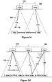
- Figures 2a to 2b depict a part of the communication network 100 depicted in Figure 1 in which two LC-enabled wireless devices 108a, 108b are served by the same LC cell 110.
- a wireless LC link 114 is available for each of the wireless devices 108a, 108b.
- the wireless LC link 114 between a first of the wireless devices 108a i.e., a "first wireless device” 108) and the LC-enabled AP 102a is unavailable.
- the unavailability of the wireless LC link 114 between the first wireless device 108 and the LC-enabled AP 102a is due to the blockage 116 in the LoS communication path therebetween.
- a second of the wireless devices 108b (i.e., a "second wireless device” 108b) is identified for relaying data between the first wireless device 108a and the communication network 100 so that data can be relayed via the D2D communication link 118 (i.e., a "first communication link” 118) between the first wireless device 108a and the second wireless device 108b and the wireless LC link 114 (i.e., a "second communication link” 114) between the second wireless device 108b and the AP 102a of the communication network 100 associated with the second wireless device 108b.
- the second wireless device 108b is in the same LC cell 110 as the first wireless device 108a.
- first communication link and “second communication” link are used. However, this does not imply that there is any particular preferred order for relaying data between the first wireless device 108 and the communication network 100 via the first and second communication links 118, 114.
- first communication link and “second communication” link are used. However, this does not imply that there is any particular preferred order for relaying data between the first wireless device 108 and the communication network 100 via the first and second communication links 118, 114.
- data is transmitted from the AP 102a to the second wireless device 108b (i.e., via the "second communication link” 114), which is then relayed by the second wireless device 108b for transmission of the data to the first wireless device 108a (i.e., via the "first communication link” 118).
- data is transmitted from the first wireless device 108a to the second wireless device 108b (i.e., via the "first communication link” 118), which is then relayed by the second wireless device 108b for transmission of the data to the AP 102a (i.e., via the "second communication link” 114).
- any of the wireless devices 108 within the communication network 100 may be the "first wireless device” and any of the other wireless devices 108 may be the "second wireless device”.
- the communication network 100 may comprise a plurality of wireless devices 108.
- a node of the communication network 100 may facilitate data communication by identifying a wireless device 108 within the communication network 100 to act as the "second wireless device” for a "first wireless device” when a wireless LC link 114 becomes unavailable.
- data may be relayed in either direction (i.e., for uplink communications and/or downlink communications) between the first wireless device and the network via one or more second wireless devices upon the wireless LC link 114 associated with the first wireless device becoming unavailable.
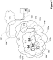
- Figures 3a to 3d depict parts of the communication network 100 depicted in Figure 1 in different scenarios.
- Figure 3a depicts a similar scenario to that of Figure 2a .
- the wireless device 108b may be served by either of the LC cells 110 provided by the two APs 102a, 102b.
- a wireless LC link 114 can be provided between the wireless device 108b and either of the APs 102a, 102b.
- both of the wireless LC links 114 associated with the AP 102a are unavailable (e.g., due to a blockage 116 in the LoS communication path with the AP 102a).
- a D2D communication link 118 i.e., a "first communication link” 118
- the second wireless device 108b cannot communicate with the AP 102a using light communication. Instead, the second wireless device 108b establishes a wireless LC link 114 (i.e., a "second communication link” 114) with the other AP 102b.
- the second wireless device 108b can relay data between the first wireless device 108a and the communication network 100 (i.e., for uplink communications and/or downlink communications) via the first and second communication links 118, 114.
- the wireless device 108b shown in Figure 3a is not present or is unavailable. Since the wireless LC link 114 between the first wireless device 108a and the AP 102a is once again unavailable, a second wireless device 108c is identified and a D2D communication link 118 (i.e., a "first communication link" 118) established between the first and second wireless devices 108a, 108c. In this example, the first and second wireless devices 108a, 108c are located in different LC cells 110. The second wireless device 108c establishes a second communication link 114 with the AP 102b.
- a D2D communication link 118 i.e., a "first communication link" 118
- the second wireless device 108b can relay data between the first wireless device 108a and the communication network 100 (i.e., for uplink communications and/or downlink communications) via the first and second communication links 118, 114.
- the first and second communication links respectively represent first and second hops (or a "dual-hop" communication link) between the AP 102 and the first wireless device 108a of the communication network 100.
- the multi-hop communication link may have more than two hops (i.e., three or more hops).
- a communication link may be established between the first wireless device 108a and a second wireless device 108c.
- a second communication link 114 may be established between the second wireless device 108c and its corresponding AP 102b so that the second wireless device 108c can relay data between the first wireless device 108a and the communication network 100 (i.e., for uplink communications and/or downlink communications).
- a direct D2D communication link cannot be established between the first and second wireless devices 108a, 108c. Therefore, another wireless device 108b enables data communication to be established between the first and second wireless devices 108a, 108c.
- the other wireless device 108b acts as a relay between the first and second wireless devices 108a, 108c.
- a triple-hop communication link is established between the AP 102 associated with the second wireless device 108c and the first wireless device 108a (i.e., to facilitate uplink communications and/or downlink communications).
- an RF communication link 120 (i.e., a "second communication link" 120) is instead provided between the second wireless device 108c and the RF-enabled AP 102c.
- the second communication link 120 is provided between another wireless device 108d (i.e., a "second wireless device") and the RF-enabled AP 102c.
- the other wireless devices 108b, 108c relay data between the first and second wireless devices 108a, 108d in three hops.
- the first communication link may utilize one or both of wireless RF communication (i.e., one type of communication) and wireless LC (i.e., another type of communication).
- wireless RF communication i.e., one type of communication
- wireless LC i.e., another type of communication
- the first communication link may be provided by one type of communication and the second communication link may be provided by the same type of communication or another type of communication.
- all three hops may be provided by the same type of communication or one or more of the hops may be provided by a different type of communication.
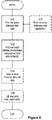
- Figure 4 is a flowchart depicting a method 200 performed in a node of a communication network 100 to enable data communication to be established (i.e., for uplink communications and/or downlink communications) between a first wireless device 108 and the communication network 100 upon a wireless LC link 114 between the first wireless device 108 and an LC-enabled AP 102 of the communication network 100 becoming unavailable.
- the node may be one of: the first wireless device 108; an AP 102 of the communication network 100; and the network node 106 of the communication network 100.
- the first wireless device 108 may itself identify a second wireless device or relay wireless device to establish a D2D communication link with, and thereafter cause the D2D communication link to be established.
- an access point may identify a second wireless device for a particular first wireless device, and cause establishment of the D2D communication link.
- a further network node (such as the network node 106 described above with respect to Figure 1 ) may cause a second wireless device to be identified and/or a D2D communication link to be established, e.g., through issuing appropriate instructions to the access point or the wireless device.
- the method steps set out below may be performed by more than one of these nodes.
- a second wireless device 108 for relaying data between the first wireless device 108 and the communication network 100 is identified so that data can be relayed via a first communication link between the first wireless device 108 and the second wireless device 108 and a second communication link between the second wireless device 108 and an AP 102 of the communication network associated with the second wireless device 108.
- the node causes establishment of at least one of: the first communication link and the second communication link responsive to a determination that the wireless LC link 114 between the first wireless device 108 and the LC-enabled AP 102 has become unavailable.
- At least one additional wireless device 108 may be identified for relaying data between the first wireless device 108 and the second wireless device 108 to enable the first communication link to be established.
- the method may identify an alternative communication route for communicating data to improve network reliability and/or robustness, for example.
- data communication via the first communication link may be enabled by at least one of: wireless Radio-Frequency, RF, communication and wireless LC.
- Data communication via the second communication link may be enabled by at least one of: wireless RF communication and wireless LC.
- the step of identifying the second wireless device 108 may comprise selecting, based on a determination that a plurality of candidate wireless devices 108 are available for providing data communication with the communication network 100, which of the candidate wireless devices 108 to use as the second wireless device 108 according to one or more criteria.
- a node of the communication network 100 may identify, for a first wireless device 108a, that a plurality of candidate wireless devices 108b, 108c, 108d are available for providing data communication with the communication network 100 (e.g., the candidate devices have active connections to the network). Based on the one or more criteria, the node may determine which wireless device(s) 108 of the plurality of candidate devices to use to enable the first and second communication links 118, 114, 120 to be established.
- At least one of the one or more criteria is based on a location of one or more of the nodes, such as: the first wireless device 108; the LC-enabled AP 102 associated with the first wireless device 108; the candidate wireless devices 108; and/or an AP 102 associated with the candidate wireless devices 108.
- the one or more criteria may comprise a criterion that the second wireless device 108 in closest proximity to the first wireless device 108 be selected as the relay device (e.g., to avoid interference effects or due to transmission power constraints, or the like).
- the closest candidate wireless device 108 may not provide an optimum solution as defined by the one or more criteria.
- the location of wireless devices may be determined or inferred based on an identity of the LC-enabled AP 102 to which the wireless device has an established CL communication link.
- LC communication links are dominated by LoS components, such that the presence of an active LC communication link with a particular LC-enabled AP can be inferred to mean that the wireless device is within a line of sight of the AP.
- At least one of the one or more criteria is based on a metric of a signal transmitted between the nodes of the network 100.
- the signal may be transmitted between one of: the first wireless device 108; the LC-enabled AP 102 associated with the first wireless device 108; the candidate wireless devices 108; or an AP 102 associated with the candidate wireless devices 108, and another of: the first wireless device 108; the LC-enabled AP 102 associated with the first wireless device 108; the candidate wireless devices 108; or an AP 102 associated with the candidate wireless device 108.
- the signal metric may comprise one or more of any suitable metric, such as received signal strength, received signal quality, signal-to-noise ratio, signal-to-interference-and-noise ratio, etc.
- an identified candidate wireless device 108b can establish a wireless LC connection 114 with the same LC-enabled AP 102a as the first wireless device 108a.
- the identified candidate wireless device 108b may be selected as the second wireless device 108 for relaying data communications.
- the candidate wireless device 108b may not be able to establish such a wireless LC link 114 with the LC-enabled AP 102a.
- a determination may be made as to whether or not another wireless LC link can be established between the candidate wireless device 108b and another LC-enabled AP 102b (i.e., an LC-enabled AP 102b serving wireless devices with a different LC cell 110 to that of the LC-enabled AP 102a associated with the first wireless device 108a).
- the identified candidate wireless device 108b may be selected as the second wireless device 108 for relaying data communications.
- a determination may be made as to whether or not a wireless RF communication link can be established between a candidate wireless device 108c and an RF communication-enabled AP 102c of the communication network 100.
- the candidate wireless device 108c may be selected as the second wireless device 108 for relaying data communications.
- further attempts to establish communication using another communication link between the first wireless device and the communication network may be performed, for example, by identifying alternative candidate wireless devices 108 and associated APs 102 and/or by attempting to establish a direct LC link (i.e., without a relaying second wireless device) between the first wireless device 108a and the LC-enabled AP 102a or another LC-enabled AP 102b.
- the one or more criteria may relate to the capabilities of the various nodes, such as the first or second wireless devices. For example, certain wireless devices may not be capable of establishing D2D communication links. The capabilities of wireless devices may be indicated by those wireless devices to the network via transmissions to the APs 102. In another example, only some of the wireless devices 108 may be LC-enabled, and only the LC-enabled network devices 108 can form LC links with corresponding LC APs and/or other LC-enabled wireless devices 108.
- a wireless device may be one or both of LC-enabled and RF communication-enabled.
- an LC-enabled wireless device may be capable of one or both of transmitting and receiving wireless LC signals.
- a wireless device may be capable of receiving LC signals but may not be capable of transmitting LC signals (in which case the wireless device may transmit using RF signals).
- a determination may be made as to whether or not LC or RF communication should be used for one or both of the first and second communication links (e.g., the determination may be made for uplink communications and/or downlink communications).
- an LC link may be established between the first wireless device and the second wireless device.
- a wireless RF communication link may be established between the first wireless device and the second wireless device.
- the second communication link may be provided by LC or RF communication (again, for one or both of uplink communications and downlink communications).
- the node may cause instructions to be provided to at least one other node of the communication network 100 regarding at least one operation to be performed if a determination is made that the wireless LC link 114 becomes unavailable.
- such instructions may be provided responsive to a determination that the wireless LC link 114 has become unavailable.
- such instructions may be provided prior to the wireless LC link 114 becoming unavailable.
- the node may proactively determine a course of action to be taken by one or more of the first wireless device 108 and the candidate wireless devices 108 should the wireless LC link 114 become unavailable in the future.
- the node may periodically obtain information regarding, for example, the location, signal metrics and/or a capability of at least one of: the first wireless device 108 and the candidate wireless devices 108.
- the node may determine from this information whether to update the instructions provided to the wireless devices 108. For example, if the location of any of the wireless devices 108 has changed, the node may re-determine which wireless device(s) 108 can be used to relay data in the event that the wireless LC link 114 is unavailable.
- DL and UL communication may be provided using the same or different communication links.
- the first communication link may be provided by wireless RF communication and the second communication link may be provided by wireless LC.
- either the same communication links may be used or at least one other communication link may be used for the UL.
- the other communication link for the UL may comprise a wireless RF communication link. Even though RF network resources may be consumed in this example, demand on the communication network may be shared between the RF network resources and the LC network resources.
- the wireless LC link 114 between the first wireless device 108 and the LC-enabled AP 102 may be determined to have become unavailable upon a signal metric of the wireless LC link being unable to meet one or more criteria.
- the one or more criteria may comprise a threshold value against which the signal metric or some other performance indicator can be compared.
- the signal metric may comprise at least one of: a received signal power; a Signal-to-Noise Ratio, SNR; and a received signal quality.
- the signal metric may monotonically increase with increasing communication link quality such that, if the signal metric is below the threshold, the wireless LC link 114 may be considered to have become unavailable.
- the wireless LC link 114 between the first wireless device 108 and the LC-enabled AP 102 is determined to have become unavailable based on a determination being made that a message transmitted from a node of the communication network 100 has not been received by another node of the communication network 100, for example, within a predetermined time interval.
- the non-receipt of the message may be due to, for example, a partial or incomplete reception of the message and/or an error in the message if it has been at least partially received.
- the node that transmits the message may be one of: an AP 102 and a wireless device 108 and the node intended to receive the message may be the other one of: the AP 102 and the wireless device 108.
- the wireless LC link 114 may be determined to have failed or become unavailable upon multiple such failed transmissions within a particular time window, or upon a particular transmission failing even after multiple retransmissions.
- Step 204 may comprise causing an association request to be sent from one of the first wireless device 108 and the second wireless device 108 to the other of the first wireless device 108 and the second wireless device 108, to enable the establishment of the first communication link 118. Responsive to receiving the association request, the other of the first wireless device and the second wireless device 108 may transmit an acknowledgement to confirm that that it has received the association request.
- the first communication link 118 may be established between the first and second wireless devices 108 so that data may be communicated therebetween.
- the step of causing establishment of at least one of the first communication link 118 and the second communication link 114, 120 may be performed responsive to a determination that one or more attempts to re-establish the wireless LC link 114 have failed. For example, prior to identifying and/or establishing the first and second communication links 118, 114, 120, one or more attempts to re-establish the wireless LC link 114 may be performed.
- the step of causing establishment of at least one of the first communication link 118 and the second communication link 114, 120 may be performed responsive to a determination that one or more attempts to establish a wireless LC link 114 with one or more further wireless LC-enabled APs 102 have failed. For example, prior to identifying and/or establishing the first and second communication links, one or more attempts to establish an alternative wireless LC link 114 with another LC-enabled AP 102 may be performed.
- the first wireless device 108 may perform a hierarchical list of actions upon failure of the wireless LC link 114. First, the first wireless device 108 may attempt to re-establish the wireless LC link 114 with the same LC-enabled AP. If that is unsuccessful, the first wireless device 108 may then attempt to establish a wireless LC link 114 with a different LC-enabled AP 102. If that is unsuccessful, the node may then cause establishment of the D2D communication link in order to relay data from the first wireless device 108 to the network. However, even then the first wireless device 108 may attempt to establish the D2D communication link in an ordered fashion.
- the node may first attempt to establish D2D communication links to second wireless devices 108 which are connected to the same LC cell as the original wireless LC link 114. If establishment of that or those D2D communication links fails, the node may attempt to establish D2D communication links to second wireless devices 108 connected to other LC cells.
- Figure 5 is a schematic diagram of a node 300 according to embodiments of the disclosure.
- the node 300 may be configured to implement any method described herein, for example, as described above with respect to Figure 4 .
- the communication network 100 described above comprises a plurality of nodes.
- the node 300 of Figure 5 may be any of the nodes described above in relation to the communication network 100.
- the node 300 comprises processing circuitry 302 (such as one or more processors, digital signal processors, general purpose processing units, etc), a machine-readable medium 304 (e.g., memory such as read-only memory (ROM), random-access memory, cache memory, flash memory devices, optical storage devices, etc) and one or more interfaces 306.
- the one or more interfaces 306 may comprise a plurality of antenna elements configurable to provide a plurality of transmit or receive beams (e.g. for transmitting or receiving wireless RF signals). Additionally or alternatively, the one or more interfaces 306 may comprise at least one LC receiving device and/or at least one LC transmitting device.
- the interface(s) 306 may additionally comprise an interface for backhaul communications, such as a wireless, wired (e.g., power-over-Ethernet) or optical interface.
- backhaul communications such as a wireless, wired (e.g., power-over-Ethernet) or optical interface.
- the components are illustrated coupled together in series; however, those skilled in the art will appreciate that the components may be coupled together in any suitable manner (e.g., via a system bus or suchlike).
- the node 300 is operable to enable data communication to be established between a first wireless device 108 and a communication network 100 upon a wireless Light Communication, LC, link between the first wireless device and an LC-enabled Access Point, AP, of the communication network becoming unavailable.
- the machine-readable medium 304 stores instructions which, when executed by the processing circuitry 302, cause the node 300 to: identify a second wireless device 108 for relaying data between the first wireless device 108 and the communication network 100 via a first communication link 118 between the first wireless device 108 and the second wireless device 108 and a second communication link 114, 120 between the second wireless device 108 and an AP 102 of the communication network 100 associated with the second wireless device 108.
- the node 300 may comprise power circuitry (not illustrated).
- the power circuitry may comprise, or be coupled to, power management circuitry and is configured to supply the components of node 300 with power for performing the functionality described herein.
- Power circuitry may receive power from a power source.
- the power source and/or power circuitry may be configured to provide power to the various components of node 300 in a form suitable for the respective components (e.g., at a voltage and current level needed for each respective component).
- the power source may either be included in, or external to, the power circuitry and/or the node 300.
- the node 300 may be connectable to an external power source (e.g., an electricity outlet) via an input circuitry or interface such as an electrical cable, whereby the external power source supplies power to the power circuitry.
- the power source may comprise a source of power in the form of a battery or battery pack which is connected to, or integrated in, the power circuitry.
- the battery may provide backup power should the external power source fail.
- Other types of power sources such as photovoltaic devices, may also be used.
- Figure 6 is a schematic diagram of a node 400 according to embodiments of the disclosure.
- the node 400 may be configured to implement any method described herein, for example, as described above with respect to Figure 4 .
- the node 400 comprises a selecting unit 402, an establishing unit 404 and one or more interfaces 406.
- the one or more interfaces 406 may comprise a plurality of antenna elements configurable to provide a plurality of transmit or receive beams (e.g. for transmitting or receiving wireless RF signals). Additionally or alternatively, the one or more interfaces 406 may comprise at least one LC receiving device and/or at least one LC transmitting device.
- the interfaces 406 may additionally comprise an interface for backhaul communications, such as a wireless, wired (e.g., power-over-Ethernet) or optical interface.
- the node 400 is operable to enable data communication to be established between a first wireless device 108 and a communication network 100 upon a wireless Light Communication, LC, link 114 between the first wireless device 108 and an LC-enabled Access Point, AP 102, of the communication network 100 becoming unavailable.
- the selecting unit 402 is configured to implement any of the methods described herein.
- the selecting unit 402 may be configured to implement the method described in relation to block 202 of Figure 2 .
- the establishment unit 404 is configured to implement any of the methods described herein.
- the establishment unit 404 may be configured to implement the method described in relation to block 204 of Figure 2 .
- unit may have conventional meaning in the field of electronics, electrical devices and/or electronic devices and may include, for example, electrical and/or electronic circuitry, devices, modules, processors, memories, logic solid state and/or discrete devices, computer programs or instructions for carrying out respective tasks, procedures, computations, outputs, and/or displaying functions, and so on, as such as those that are described herein.
- a communication system includes telecommunication network 1210 (which may comprise or be referred to as a communication network), such as a 3GPP-type cellular network, which comprises access network 1211, such as a radio access network, and core network 1214.
- Access network 1211 comprises a plurality of base stations 1212a, 1212b, 1212c, such as NBs, eNBs, gNBs or other types of wireless access points, each defining a corresponding coverage area 1213a, 1213b, 1213c.
- Each base station 1212a, 1212b, 1212c is connectable to core network 1214 over a wired or wireless connection 1215.
- a first UE 1291 located in coverage area 1213c is configured to wirelessly connect to, or be paged by, the corresponding base station 1212c.
- a second UE 1292 in coverage area 1213a is wirelessly connectable to the corresponding base station 1212a. While a plurality of UEs 1291, 1292 are illustrated in this example, the disclosed embodiments are equally applicable to a situation where a sole UE is in the coverage area or where a sole UE is connecting to the corresponding base station 1212.
- Telecommunication network 1210 is itself connected to host computer 1230, which may be embodied in the hardware and/or software of a standalone server, a cloudimplemented server, a distributed server or as processing resources in a server farm.
- Host computer 1230 may be under the ownership or control of a service provider, or may be operated by the service provider or on behalf of the service provider.
- Connections 1221 and 1222 between telecommunication network 1210 and host computer 1230 may extend directly from core network 1214 to host computer 1230 or may go via an optional intermediate network 1220.
- Intermediate network 1220 may be one of, or a combination of more than one of, a public, private or hosted network; intermediate network 1220, if any, may be a backbone network or the Internet; in particular, intermediate network 1220 may comprise two or more sub-networks (not shown).
- the communication system of Figure 7 as a whole enables connectivity between the connected UEs 1291, 1292 and host computer 1230.
- the connectivity may be described as an over-the-top (OTT) connection 1250.
- Host computer 1230 and the connected UEs 1291, 1292 are configured to communicate data and/or signaling via OTT connection 1250, using access network 1211, core network 1214, any intermediate network 1220 and possible further infrastructure (not shown) as intermediaries.
- OTT connection 1250 may be transparent in the sense that the participating communication devices through which OTT connection 1250 passes are unaware of routing of uplink and downlink communications.
- base station 1212 may not or need not be informed about the past routing of an incoming downlink communication with data originating from host computer 1230 to be forwarded (e.g., handed over) to a connected UE 1291. Similarly, base station 1212 need not be aware of the future routing of an outgoing uplink communication originating from the UE 1291 towards the host computer 1230.
- host computer 1310 comprises hardware 1315 including communication interface 1316 configured to set up and maintain a wired or wireless connection with an interface of a different communication device of communication system 1300.
- Host computer 1310 further comprises processing circuitry 1318, which may have storage and/or processing capabilities.
- processing circuitry 1318 may comprise one or more programmable processors, application-specific integrated circuits, field programmable gate arrays or combinations of these (not shown) adapted to execute instructions.
- Host computer 1310 further comprises software 1311, which is stored in or accessible by host computer 1310 and executable by processing circuitry 1318.
- Software 1311 includes host application 1312.
- Host application 1312 may be operable to provide a service to a remote user, such as UE 1330 connecting via OTT connection 1350 terminating at UE 1330 and host computer 1310. In providing the service to the remote user, host application 1312 may provide user data which is transmitted using OTT connection 1350.
- Communication system 1300 further includes base station 1320 provided in a telecommunication system and comprising hardware 1325 enabling it to communicate with host computer 1310 and with UE 1330.
- Hardware 1325 may include communication interface 1326 for setting up and maintaining a wired or wireless connection with an interface of a different communication device of communication system 1300, as well as radio interface 1327 for setting up and maintaining at least wireless connection 1370 with UE 1330 located in a coverage area (not shown in Figure 8 ) served by base station 1320.
- Communication interface 1326 may be configured to facilitate connection 1360 to host computer 1310. Connection 1360 may be direct or it may pass through a core network (not shown in Figure 8 ) of the telecommunication system and/or through one or more intermediate networks outside the telecommunication system.
- hardware 1325 of base station 1320 further includes processing circuitry 1328, which may comprise one or more programmable processors, application-specific integrated circuits, field programmable gate arrays or combinations of these (not shown) adapted to execute instructions.
- processing circuitry 1328 may comprise one or more programmable processors, application-specific integrated circuits, field programmable gate arrays or combinations of these (not shown) adapted to execute instructions.
- Base station 1320 further has software 1321 stored internally or accessible via an external connection.
- Communication system 1300 further includes UE 1330 already referred to. Its hardware 1335 may include radio interface 1337 configured to set up and maintain wireless connection 1370 with a base station serving a coverage area in which UE 1330 is currently located. Hardware 1335 of UE 1330 further includes processing circuitry 1338, which may comprise one or more programmable processors, application-specific integrated circuits, field programmable gate arrays or combinations of these (not shown) adapted to execute instructions. UE 1330 further comprises software 1331, which is stored in or accessible by UE 1330 and executable by processing circuitry 1338. Software 1331 includes client application 1332. Client application 1332 may be operable to provide a service to a human or non-human user via UE 1330, with the support of host computer 1310.
- an executing host application 1312 may communicate with the executing client application 1332 via OTT connection 1350 terminating at UE 1330 and host computer 1310.
- client application 1332 may receive request data from host application 1312 and provide user data in response to the request data.
- OTT connection 1350 may transfer both the request data and the user data.
- Client application 1332 may interact with the user to generate the user data that it provides.
- host computer 1310, base station 1320 and UE 1330 illustrated in Figure 8 may be similar or identical to host computer 1230, one of base stations 1212a, 1212b, 1212c and one of UEs 1291, 1292 of Figure 7 , respectively.
- the inner workings of these entities may be as shown in Figure 8 and independently, the surrounding network topology may be that of Figure 8 .
- OTT connection 1350 has been drawn abstractly to illustrate the communication between host computer 1310 and UE 1330 via base station 1320, without explicit reference to any intermediary devices and the precise routing of messages via these devices.
- Network infrastructure may determine the routing, which it may be configured to hide from UE 1330 or from the service provider operating host computer 1310, or both. While OTT connection 1350 is active, the network infrastructure may further take decisions by which it dynamically changes the routing (e.g., on the basis of load balancing consideration or reconfiguration of the network).
- Wireless connection 1370 between UE 1330 and base station 1320 is in accordance with the teachings of the embodiments described throughout this disclosure.
- One or more of the various embodiments improve the performance of OTT services provided to UE 1330 using OTT connection 1350, in which wireless connection 1370 forms the last segment. More precisely, the teachings of these embodiments may improve the reliability of data transmission to and from the UE 1330 and thereby provide benefits such as reduced user waiting time.
- a measurement procedure may be provided for the purpose of monitoring data rate, latency and other factors on which the one or more embodiments improve.
- the measurement procedure and/or the network functionality for reconfiguring OTT connection 1350 may be implemented in software 1311 and hardware 1315 of host computer 1310 or in software 1331 and hardware 1335 of UE 1330, or both.
- sensors (not shown) may be deployed in or in association with communication devices through which OTT connection 1350 passes; the sensors may participate in the measurement procedure by supplying values of the monitored quantities exemplified above, or supplying values of other physical quantities from which software 1311, 1331 may compute or estimate the monitored quantities.
- the reconfiguring of OTT connection 1350 may include message format, retransmission settings, preferred routing etc.; the reconfiguring need not affect base station 1320, and it may be unknown or imperceptible to base station 1320. Such procedures and functionalities may be known and practiced in the art.
- measurements may involve proprietary UE signaling facilitating host computer 1310's measurements of throughput, propagation times, latency and the like.
- the measurements may be implemented in that software 1311 and 1331 causes messages to be transmitted, in particular empty or 'dummy' messages, using OTT connection 1350 while it monitors propagation times, errors etc.
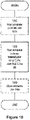
- FIG. 9 is a flowchart illustrating a method implemented in a communication system, in accordance with one embodiment.
- the communication system includes a host computer, a base station and a UE which may be those described with reference to Figures 7 and 8 .
- the host computer provides user data.
- substep 1411 (which may be optional) of step 1410, the host computer provides the user data by executing a host application.
- the host computer initiates a transmission carrying the user data to the UE.
- step 1430 the base station transmits to the UE the user data which was carried in the transmission that the host computer initiated, in accordance with the teachings of the embodiments described throughout this disclosure.
- step 1440 the UE executes a client application associated with the host application executed by the host computer.
- FIG 10 is a flowchart illustrating a method implemented in a communication system, in accordance with one embodiment.
- the communication system includes a host computer, a base station and a UE which may be those described with reference to Figures 7 and 8 .
- the host computer provides user data.
- the host computer provides the user data by executing a host application.
- the host computer initiates a transmission carrying the user data to the UE.
- the transmission may pass via the base station, in accordance with the teachings of the embodiments described throughout this disclosure.
- step 1530 (which may be optional), the UE receives the user data carried in the transmission.
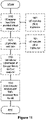
- FIG 11 is a flowchart illustrating a method implemented in a communication system, in accordance with one embodiment.
- the communication system includes a host computer, a base station and a UE which may be those described with reference to Figures 7 and 8 .
- the UE receives input data provided by the host computer.
- the UE provides user data.
- substep 1621 (which may be optional) of step 1620, the UE provides the user data by executing a client application.
- substep 1611 (which may be optional) of step 1610, the UE executes a client application which provides the user data in reaction to the received input data provided by the host computer.
- the executed client application may further consider user input received from the user.
- the UE initiates, in substep 1630 (which may be optional), transmission of the user data to the host computer.
- step 1640 of the method the host computer receives the user data transmitted from the UE, in accordance with the teachings of the embodiments described throughout this disclosure.
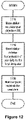
- FIG 12 is a flowchart illustrating a method implemented in a communication system, in accordance with one embodiment.
- the communication system includes a host computer, a base station and a UE which may be those described with reference to Figures 7 and 8 .
- the base station receives user data from the UE.
- the base station initiates transmission of the received user data to the host computer.
- the host computer receives the user data carried in the transmission initiated by the base station.
Landscapes
- Engineering & Computer Science (AREA)
- Computer Networks & Wireless Communication (AREA)
- Signal Processing (AREA)
- Physics & Mathematics (AREA)
- Electromagnetism (AREA)
- Mobile Radio Communication Systems (AREA)
- Optical Communication System (AREA)
Claims (18)
- Verfahren, das in einem Knoten (102, 106, 108) eines Kommunikationsnetzwerks (100) durchgeführt wird, wobei das Verfahren ermöglicht, dass eine Datenkommunikation zwischen einer ersten drahtlosen Vorrichtung (108) und dem Kommunikationsnetzwerk hergestellt wird, sobald eine drahtlose Lichtkommunikationsverbindung, LC-Verbindung, (114) zwischen der ersten drahtlosen Vorrichtung und einem LC-fähigen Zugangspunkt, AP, (102) des Kommunikationsnetzwerks nicht verfügbar wird, das Verfahren umfassend:
Identifizieren einer zweiten drahtlosen Vorrichtung (108) zum Weiterleiten von Daten zwischen der ersten drahtlosen Vorrichtung und dem Kommunikationsnetzwerk über eine erste Kommunikationsverbindung (118) zwischen der ersten drahtlosen Vorrichtung und der zweiten drahtlosen Vorrichtung und eine zweite Kommunikationsverbindung (114, 120) zwischen der zweiten drahtlosen Vorrichtung und einem AP des Kommunikationsnetzwerks, der der zweiten drahtlosen Vorrichtung zugeordnet ist, wobei eine Datenkommunikation über mindestens eines von: der ersten Kommunikationsverbindung (118) und der zweiten Kommunikationsverbindung (114, 120) durch eine drahtlose Hochfrequenzkommunikation, HF-Kommunikation, ermöglicht wird. - Verfahren nach Anspruch 1, umfassend das Identifizieren von mindestens einer zusätzlichen drahtlosen Vorrichtung (108) zum Weiterleiten von Daten zwischen der ersten drahtlosen Vorrichtung (108) und der zweiten drahtlosen Vorrichtung (108), um zu ermöglichen, dass die erste Kommunikationsverbindung (118) hergestellt wird.
- Verfahren nach Anspruch 1 oder 2, wobei:eine Datenkommunikation über eine von der ersten Kommunikationsverbindung (118) und der zweiten Kommunikationsverbindung (114, 120) durch eine drahtlose HF-Kommunikation ermöglicht wird undeine Datenkommunikation über die andere von der ersten Kommunikationsverbindung (118) und der zweiten Kommunikationsverbindung (114, 120) durch eine drahtlose LC ermöglicht wird.
- Verfahren nach einem der vorstehenden Ansprüche, umfassend das Bewirken einer Herstellung von mindestens einer von: der ersten Kommunikationsverbindung (118) und der zweiten Kommunikationsverbindung (114, 120) als Reaktion auf eine Bestimmung, dass die drahtlose LC-Verbindung (114) zwischen der ersten drahtlosen Vorrichtung (108) und dem LC-fähigen AP (102) nicht verfügbar geworden ist.
- Verfahren nach Anspruch 4, wobei bestimmt wird, dass die drahtlose LC-Verbindung zwischen der ersten drahtlosen Vorrichtung und dem LC-fähigen AP nicht verfügbar geworden ist, sobald eine Signalmetrik der drahtlosen LC-Verbindung nicht in der Lage ist, ein oder mehrere Kriterien zu erfüllen.
- Verfahren nach Anspruch 5, wobei die Signalmetrik mindestens eines umfasst von: einer Empfangssignalleistung; einem Signal-Rausch-Verhältnis, SNR, und einer Empfangssignalqualität.
- Verfahren nach Anspruch 4, 5 oder 6, wobei bestimmt wird, dass die drahtlose LC-Verbindung (114) zwischen der ersten drahtlosen Vorrichtung (108) und dem LC-fähigen AP (102) nicht verfügbar geworden ist, sobald eine Bestimmung erfolgt, dass die Übertragung einer Nachricht zwischen der ersten drahtlosen Vorrichtung (108) und dem LC-fähigen AP (102) fehlgeschlagen ist oder die Zeit überschritten hat.
- Verfahren nach einem der Ansprüche 4 bis 7, wobei das Bewirken, dass die Herstellung der ersten Kommunikationsverbindung (118) ein Bewirken umfasst, dass eine Zuordnungsanforderung von einer von der ersten drahtlosen Vorrichtung (108) und der zweiten drahtlosen Vorrichtung (108) an die andere von der ersten drahtlosen Vorrichtung und der zweiten drahtlosen Vorrichtung gesendet wird, um die Herstellung der ersten Kommunikationsverbindung zu ermöglichen.
- Verfahren nach einem der Ansprüche 4 bis 8, wobei der Schritt des Bewirkens der Herstellung von mindestens einer von der ersten Kommunikationsverbindung (118) und der zweiten Kommunikationsverbindung (114, 120) als Reaktion auf eine Bestimmung, dass ein oder mehrere Versuche zur erneuten Herstellung der drahtlosen LC-Verbindung (114) fehlgeschlagen sind, durchgeführt wird.
- Verfahren nach einem der Ansprüche 4 bis 9, wobei der Schritt des Bewirkens der Herstellung von mindestens einer von der ersten Kommunikationsverbindung (118) und der zweiten Kommunikationsverbindung (114, 120) als Reaktion auf eine Bestimmung, dass ein oder mehrere Versuche zur Herstellung einer drahtlosen LC-Verbindung mit einem oder mehreren weiteren drahtlosen LC-fähigen APs fehlgeschlagen sind, durchgeführt wird.
- Verfahren nach einem der vorstehenden Ansprüche, wobei das Identifizieren der zweiten drahtlosen Vorrichtung (108) ein Auswählen, basierend auf einer Bestimmung, dass eine Vielzahl von möglichen drahtlosen Vorrichtungen (108) zum Bereitstellen einer Datenkommunikation mit dem Kommunikationsnetzwerk (100) verfügbar ist, welche der möglichen drahtlosen Vorrichtungen als die zweite drahtlose Vorrichtung verwendet wird, gemäß einem oder mehreren Kriterien umfasst.
- Verfahren nach Anspruch 11, wobei mindestens eines von dem einen oder den mehreren Kriterien auf einem Ort basiert von mindestens einem von: der ersten drahtlosen Vorrichtung (108); dem LC-fähigen AP (102), der der ersten drahtlosen Vorrichtung zugeordnet ist; den möglichen drahtlosen Vorrichtungen (108) und einem AP (102), der den möglichen drahtlosen Vorrichtungen zugeordnet ist.
- Verfahren nach Anspruch 11 oder 12, wobei mindestens eines von dem einen oder den mehreren Kriterien auf einer Signalmetrik einer drahtlosen Vorrichtung (108) basiert, die übertragen wird zwischen einem von: der ersten drahtlosen Vorrichtung (108); dem LC-fähigen AP (102), der der ersten drahtlosen Vorrichtung zugeordnet ist; den möglichen drahtlosen Vorrichtungen (108) oder einem AP (102), der den möglichen drahtlosen Vorrichtungen zugeordnet ist, und einem anderen von: der ersten drahtlosen Vorrichtung; dem LC-fähigen AP, der der ersten drahtlosen Vorrichtung zugeordnet ist; den möglichen drahtlosen Vorrichtungen oder einem AP, der der möglichen drahtlosen Vorrichtung zugeordnet ist.
- Verfahren nach einem der vorstehenden Ansprüche, umfassend:Bestimmen, ob eine drahtlose LC-Verbindung zwischen einer möglichen drahtlosen Vorrichtung (108b) und dem LC-fähigen AP (102a), der der ersten drahtlosen Vorrichtung (108a) zugeordnet ist, hergestellt werden kann oder nicht,wobei, wenn die drahtlose LC-Verbindung hergestellt werden kann, das Verfahren ein Auswählen der möglichen drahtlosen Vorrichtung (108b) als die zweite drahtlose Vorrichtung umfasst, oder wenn die drahtlose LC-Verbindung nicht hergestellt werden kann, das Verfahren ein Bestimmen, ob eine andere drahtlose LC-Verbindung zwischen einer möglichen drahtlosen Vorrichtung (108b, 108c) und einem anderen LC-fähigen AP (102b) hergestellt werden kann oder nicht, umfasst, wobei, wenn die andere drahtlose LC-Verbindung hergestellt werden kann, das Verfahren ein Auswählen der möglichen drahtlosen Vorrichtung (108b, 108c) als die zweite drahtlose Vorrichtung umfasst, oder wenn die andere drahtlose LC-Verbindung nicht hergestellt werden kann, das Verfahren ein Bestimmen, ob eine drahtlose HF-Kommunikationsverbindung zwischen einer möglichen drahtlosen Vorrichtung (108c, 108d) und einem anderen HF-fähigen AP (102c) des Kommunikationsnetzwerks (100) hergestellt werden kann oder nicht, umfasst,wobei, wenn die HF-Kommunikationsverbindung hergestellt werden kann, das Verfahren ein Auswählen der möglichen drahtlosen Vorrichtung (108c, 108d) als die zweite drahtlose Vorrichtung umfasst, oder wenn die HF-Kommunikationsverbindung nicht hergestellt werden kann, das Verfahren ein Versuchen, eine Kommunikation unter Verwendung einer anderen Kommunikationsverbindung zwischen der ersten drahtlosen Vorrichtung und dem Kommunikationsnetzwerk herzustellen, umfasst.
- Verfahren nach einem der vorstehenden Ansprüche, umfassend: als Reaktion darauf, dass eine Bestimmung erfolgt, dass die erste Kommunikationsverbindung durch eine LC bereitgestellt werden kann, Herstellen einer LC-Verbindung zwischen der ersten drahtlosen Vorrichtung und der zweiten drahtlosen Vorrichtung und als Reaktion darauf, dass eine Bestimmung erfolgt, dass die erste Kommunikationsverbindung nicht durch eine LC bereitgestellt werden kann, Herstellen einer drahtlosen HF-Kommunikationsverbindung zwischen der ersten drahtlosen Vorrichtung und der zweiten drahtlosen Vorrichtung.
- Verfahren nach einem der vorstehenden Ansprüche, wobei der Knoten eines ist von: der ersten drahtlosen Vorrichtung (108); einem AP (102) des Kommunikationsnetzwerks (100) und einem Netzknoten (106) des Kommunikationsnetzwerks.
- Nichttransitorisches maschinenlesbares Medium (304), das Anweisungen zur Ausführung durch Verarbeitungsschaltlogik (302) eines Knotens (300) eines Kommunikationsnetzwerks speichert, um zu ermöglichen, dass eine Datenkommunikation zwischen einer ersten drahtlosen Vorrichtung (108) und dem Kommunikationsnetzwerk hergestellt wird, sobald eine drahtlose Lichtkommunikationsverbindung, LC-Verbindung, (114) zwischen der ersten drahtlosen Vorrichtung und einem LC-fähigen Zugangspunkt, AP, (102) des Kommunikationsnetzwerks nicht verfügbar wird, wobei die Ausführung der Anweisungen durch die Verarbeitungsschaltlogik den Knoten veranlasst zum:
Identifizieren einer zweiten drahtlosen Vorrichtung (108) zum Weiterleiten von Daten zwischen der ersten drahtlosen Vorrichtung und dem Kommunikationsnetzwerk über eine erste Kommunikationsverbindung (118) zwischen der ersten drahtlosen Vorrichtung und der zweiten drahtlosen Vorrichtung und eine zweite Kommunikationsverbindung (114, 120) zwischen der zweiten drahtlosen Vorrichtung und einem AP (102) des Kommunikationsnetzwerks, der der zweiten drahtlosen Vorrichtung zugeordnet ist, wobei eine Datenkommunikation über mindestens eines von: der ersten Kommunikationsverbindung (118) und der zweiten Kommunikationsverbindung (114, 120) durch eine drahtlose Hochfrequenzkommunikation, HF-Kommunikation, ermöglicht wird. - Knoten (300) zum Ermöglichen, dass eine Datenkommunikation zwischen einer ersten drahtlosen Vorrichtung (108) und einem Kommunikationsnetzwerk (100) hergestellt wird, sobald eine drahtlose Lichtkommunikationsverbindung, LC-Verbindung, (114) zwischen der ersten drahtlosen Vorrichtung und einem LC-fähigen Zugangspunkt, AP, (102) des Kommunikationsnetzwerks nicht verfügbar wird, der Knoten umfassend die Verarbeitungsschaltlogik (302) und ein nichttransitorisches maschinenlesbares Medium (304), wobei das nichttransitorische maschinenlesbare Medium Anweisungen speichert, die, wenn sie durch die Verarbeitungsschaltlogik ausgeführt werden, den Knoten veranlassen, das Verfahren nach einem der Ansprüche 1-16 durchzuführen.
Applications Claiming Priority (1)
| Application Number | Priority Date | Filing Date | Title |
|---|---|---|---|
| PCT/EP2019/066720 WO2020259797A1 (en) | 2019-06-24 | 2019-06-24 | Methods, apparatus and machine-readable mediums related to wireless communication in communication networks |
Publications (2)
| Publication Number | Publication Date |
|---|---|
| EP3987689A1 EP3987689A1 (de) | 2022-04-27 |
| EP3987689B1 true EP3987689B1 (de) | 2022-12-07 |
Family
ID=67106028
Family Applications (1)
| Application Number | Title | Priority Date | Filing Date |
|---|---|---|---|
| EP19734039.1A Active EP3987689B1 (de) | 2019-06-24 | 2019-06-24 | Verfahren, vorrichtung und maschinenlesbare medien für die drahtlose kommunikation in kommunikationsnetzwerken |
Country Status (8)
| Country | Link |
|---|---|
| US (1) | US12081263B2 (de) |
| EP (1) | EP3987689B1 (de) |
| JP (1) | JP7376622B2 (de) |
| CN (1) | CN114270730A (de) |
| BR (1) | BR112021026386A2 (de) |
| ES (1) | ES2935782T3 (de) |
| MX (1) | MX2021015981A (de) |
| WO (1) | WO2020259797A1 (de) |
Families Citing this family (3)
| Publication number | Priority date | Publication date | Assignee | Title |
|---|---|---|---|---|
| JP7433512B2 (ja) * | 2020-07-17 | 2024-02-19 | シグニファイ ホールディング ビー ヴィ | 光ワイヤレス通信受信ユニット、システム及び方法 |
| CN113900063B (zh) * | 2021-09-17 | 2025-03-14 | 湖北文理学院 | 一种可见光定位辅助的多用户光通信系统及方法 |
| JP7829429B2 (ja) * | 2022-07-20 | 2026-03-13 | 京セラ株式会社 | 光通信システム、基地局、及び移動機 |
Family Cites Families (49)
| Publication number | Priority date | Publication date | Assignee | Title |
|---|---|---|---|---|
| NL78387C (de) | 1946-10-04 | |||
| JP2000059382A (ja) | 1998-08-07 | 2000-02-25 | Toshiba Corp | 通信ルーチング方法およびシステムとこのシステムに用いる送信用発光器 |
| US6842439B2 (en) | 2002-06-17 | 2005-01-11 | Harris Corporation | Free space optical terminal with ad hoc network back-up and associated methods |
| JP2004364179A (ja) | 2003-06-06 | 2004-12-24 | Ricoh Co Ltd | 無線lanシステム、無線lanアクセスポイント及びクライアント |
| JP4606055B2 (ja) | 2004-04-21 | 2011-01-05 | 株式会社バッファロー | 暗号鍵設定システム、アクセスポイントおよび暗号鍵設定方法 |
| JP5311722B2 (ja) | 2006-05-19 | 2013-10-09 | 株式会社ヤマザキ | 気体混入水生成装置及び加湿装置 |
| US7577445B2 (en) | 2006-08-03 | 2009-08-18 | Ntt Docomo, Inc. | Line-of-sight (LOS) or non-LOS (NLOS) identification method using multipath channel statistics |
| JP5372055B2 (ja) | 2011-03-24 | 2013-12-18 | 日本電信電話株式会社 | 無線通信装置およびビーム制御方法 |
| CA2858171C (en) | 2011-12-15 | 2017-12-05 | Intel Corporation | Use of location information in multi-radio devices for mmwave beamforming |
| KR101320761B1 (ko) | 2012-01-20 | 2013-10-21 | 국민대학교산학협력단 | 상호협동적 가시광 통신방식을 이용한 링크 리커버리 방법 |
| JP5871737B2 (ja) | 2012-07-05 | 2016-03-01 | Kddi株式会社 | 無線通信端末、基地局、無線通信方法、通信方法および無線通信システム |
| WO2014036150A1 (en) | 2012-08-28 | 2014-03-06 | Interdigital Patent Holdings, Inc. | Method for handover of a communication link using a primary beam |
| US10158391B2 (en) | 2012-10-15 | 2018-12-18 | Qualcomm Incorporated | Wireless area network enabled mobile device accessory |
| US9525486B2 (en) | 2012-11-27 | 2016-12-20 | Extreme Networks, Inc. | Visible light communications personal area network controller and access point systems and methods |
| US9143230B2 (en) | 2012-12-01 | 2015-09-22 | Qualcomm Incorporated | Methods and apparatus for communications using visible light communications signaling in combination with wireless radio signaling |
| US9166683B2 (en) | 2013-02-14 | 2015-10-20 | Qualcomm Incorporated | Methods and apparatus for efficient joint power line and visible light communication |
| CN103237292B (zh) | 2013-05-13 | 2015-09-09 | 钟国峰 | 一种基于定位器的定位方法 |
| CN103259592B (zh) | 2013-05-24 | 2016-05-11 | 江苏大学 | 一种可见光通信网与wlan融合方法 |
| EP3080925B1 (de) | 2013-12-12 | 2020-07-22 | Telefonaktiebolaget LM Ericsson (publ) | Verfahren und netzwerkknoten für rundfunk |
| EP3089546B1 (de) | 2013-12-26 | 2020-01-01 | Sony Corporation | Informationsverarbeitungsvorrichtung, informationsverarbeitungsverfahren und programm |
| WO2015104802A1 (ja) | 2014-01-08 | 2015-07-16 | 富士通株式会社 | 無線通信システム、基地局装置、及び無線通信システムにおけるデータ転送方法 |
| CN106662322A (zh) | 2014-08-01 | 2017-05-10 | 飞利浦灯具控股公司 | 具有无线电模块的照明器 |
| CN104202088B (zh) * | 2014-09-18 | 2017-04-05 | 北京智谷睿拓技术服务有限公司 | 可见光通信方法及可见光通信装置 |
| US10020577B2 (en) | 2014-11-25 | 2018-07-10 | Qualcomm Incorporated | Technique for detection of line-of-sight transmissions using millimeter wave communication devices |
| US9872296B2 (en) | 2015-01-06 | 2018-01-16 | Qualcomm Incorporated | Techniques for beam shaping at a millimeter wave base station and a wireless device and fast antenna subarray selection at a wireless device |
| ES2755366T3 (es) | 2015-05-13 | 2020-04-22 | Ericsson Telefon Ab L M | Formación de haz |
| JP2017005579A (ja) | 2015-06-12 | 2017-01-05 | 日本無線株式会社 | ミリ波通信システムおよびミリ波通信方法 |
| US20170047994A1 (en) | 2015-08-10 | 2017-02-16 | Stmicroelectronics, Inc. | Visible light and power-line communication-based system with location-based services |
| JP6575759B2 (ja) | 2015-11-09 | 2019-09-18 | パナソニックIpマネジメント株式会社 | データ転送システム、データ送信装置およびデータ受信装置 |
| EP3375112B1 (de) | 2015-11-10 | 2019-12-18 | Fraunhofer Gesellschaft zur Förderung der angewandten Forschung E.V. | System und verfahren zur bereitstellung einer drahtlosen kommunikation mit einer mobilen vorrichtung |
| GB2546099B (en) | 2016-01-08 | 2019-05-29 | Samsung Electronics Co Ltd | Initial access method |
| GB201600968D0 (en) | 2016-01-19 | 2016-03-02 | Qatar Foundation For Education Science And Community Dev | A visible light communication system |
| WO2017171901A1 (en) | 2016-03-29 | 2017-10-05 | Intel IP Corporation | Frame structures for beam switching and refinement in cellular systems |
| US11791882B2 (en) | 2016-04-13 | 2023-10-17 | Qualcomm Incorporated | System and method for beam management |
| WO2017184190A1 (en) | 2016-04-18 | 2017-10-26 | Intel Corporation | Selection of beamforming directions based on learned performance |
| PL3236594T3 (pl) | 2016-04-19 | 2020-01-31 | Ipcom Gmbh & Co. Kg | Ustanowienia połączenia radiowego |
| WO2018017840A1 (en) | 2016-07-20 | 2018-01-25 | Convida Wireless, Llc | Mobility for radio devices using beamforming and selection |
| KR20240006080A (ko) | 2016-08-11 | 2024-01-12 | 인터디지탈 패튼 홀딩스, 인크 | 뉴 라디오를 위한 유연한 프레임 구조에서의 빔포밍 스위핑 및 트레이닝 |
| US10165483B1 (en) | 2016-10-04 | 2018-12-25 | Sprint Spectrum Lp | Mitigating interference in a distributed antenna system |
| US20180132116A1 (en) | 2016-10-26 | 2018-05-10 | Invensense Inc. | Systems and methods for motion assisted communication |
| CN106656326B (zh) | 2016-10-27 | 2019-03-29 | 南方科技大学 | 可见光辅助中继选择的控制方法、控制装置及无线局域网 |
| ES2959852T3 (es) | 2016-11-04 | 2024-02-28 | Ericsson Telefon Ab L M | Identificación de un haz para acceder a una celda de destino de un traspaso inalámbrico |
| US10771123B2 (en) | 2017-02-01 | 2020-09-08 | Yiming Huo | Distributed phased arrays based MIMO (DPA-MIMO) for next generation wireless user equipment hardware design and method |
| US10499307B2 (en) * | 2017-03-27 | 2019-12-03 | Futurewei Technologies, Inc. | System and method for dynamic data relaying |
| US10778330B1 (en) | 2018-08-03 | 2020-09-15 | Synapse Wireless, Inc. | Identification of orphaned light sources in wireless lighting networks |
| GB201816598D0 (en) * | 2018-10-11 | 2018-11-28 | Purelifi Ltd | Signal retransmission system and method |
| US20210067247A1 (en) | 2019-05-28 | 2021-03-04 | E-Lambda LLC | Dynamic free-space femto-cells for high speed optical communication |
| US11108459B2 (en) * | 2019-06-19 | 2021-08-31 | Qualcomm Incorporated | Millimeter wave relay link discovery |
| JP7322950B2 (ja) * | 2019-06-20 | 2023-08-08 | 日本電信電話株式会社 | 無線通信システム、無線通信方法及び端末装置 |
-
2019
- 2019-06-24 EP EP19734039.1A patent/EP3987689B1/de active Active
- 2019-06-24 MX MX2021015981A patent/MX2021015981A/es unknown
- 2019-06-24 ES ES19734039T patent/ES2935782T3/es active Active
- 2019-06-24 CN CN201980099714.3A patent/CN114270730A/zh active Pending
- 2019-06-24 WO PCT/EP2019/066720 patent/WO2020259797A1/en not_active Ceased
- 2019-06-24 US US17/620,929 patent/US12081263B2/en active Active
- 2019-06-24 BR BR112021026386A patent/BR112021026386A2/pt unknown
- 2019-06-24 JP JP2021576350A patent/JP7376622B2/ja active Active
Also Published As
| Publication number | Publication date |
|---|---|
| EP3987689A1 (de) | 2022-04-27 |
| CN114270730A (zh) | 2022-04-01 |
| ES2935782T3 (es) | 2023-03-10 |
| US12081263B2 (en) | 2024-09-03 |
| MX2021015981A (es) | 2022-01-24 |
| WO2020259797A1 (en) | 2020-12-30 |
| BR112021026386A2 (pt) | 2022-02-08 |
| JP2022538827A (ja) | 2022-09-06 |
| US20220329320A1 (en) | 2022-10-13 |
| JP7376622B2 (ja) | 2023-11-08 |
Similar Documents
| Publication | Publication Date | Title |
|---|---|---|
| US20220078641A1 (en) | Wireless Backhaul Resiliency | |
| US9155012B2 (en) | Method, apparatus, and related computer program product for load balancing in a relay network | |
| US7965681B2 (en) | Channel allocation procedure in a meshed network | |
| US9860905B2 (en) | Method and system for providing service in a wireless communication system | |
| US11509391B2 (en) | Adaptive multiple access scheme in integrated access and backhaul networks | |
| US20200059771A1 (en) | Handling communication of data in a bluetooth low energy (ble), mesh network | |
| BR112021006873A2 (pt) | aparelhos, métodos e programas de controle de comunicação e de comunicação, e, sistema de comunicação. | |
| US11528626B2 (en) | Radio link monitoring (RLM) procedure for a wireless device configured to operate using first and second operational modes within an overlapping time in a first cell | |
| US9729388B2 (en) | Method and apparatus for wireless link recovery between BSs in a wireless communication system | |
| EP3987689B1 (de) | Verfahren, vorrichtung und maschinenlesbare medien für die drahtlose kommunikation in kommunikationsnetzwerken | |
| US11076348B2 (en) | Method of neighbor discovery and wireless inter-connection for cellular mesh network | |
| US10455627B2 (en) | Data transmission link establishment apparatus and method, and communications system | |
| US20170367133A1 (en) | Communication device performing device-to-device communication and operating method thereof | |
| CN114270908B (zh) | 用于物理小区标识符冲突检测的方法和装置 | |
| US11399325B2 (en) | High-gain beam handover | |
| US10506450B2 (en) | Method and arrangement for relaying | |
| US20260019917A1 (en) | Relay communication sidelink based on quality of service (qos) requirements | |
| CN112154710B (zh) | 管理大规模多输入多输出基站 | |
| US20240284299A1 (en) | Conditional communication path switch from current indirect path to alternate indirect path | |
| EP2987308B1 (de) | Niedrigleistungs-mobilkommunikation durch mesh-netzwerk | |
| WO2022171287A1 (en) | Redundancy function for radio network robustness | |
| US11463950B1 (en) | Power management of secondary node based on network conditions | |
| KR20260048323A (ko) | 유연한 중계 노드들을 사용한 메시지 전달 | |
| HK1220298B (en) | Low power mobile communications through mesh network |
Legal Events
| Date | Code | Title | Description |
|---|---|---|---|
| STAA | Information on the status of an ep patent application or granted ep patent |
Free format text: STATUS: UNKNOWN |
|
| STAA | Information on the status of an ep patent application or granted ep patent |
Free format text: STATUS: THE INTERNATIONAL PUBLICATION HAS BEEN MADE |
|
| PUAI | Public reference made under article 153(3) epc to a published international application that has entered the european phase |
Free format text: ORIGINAL CODE: 0009012 |
|
| STAA | Information on the status of an ep patent application or granted ep patent |
Free format text: STATUS: REQUEST FOR EXAMINATION WAS MADE |
|
| 17P | Request for examination filed |
Effective date: 20220120 |
|
| AK | Designated contracting states |
Kind code of ref document: A1 Designated state(s): AL AT BE BG CH CY CZ DE DK EE ES FI FR GB GR HR HU IE IS IT LI LT LU LV MC MK MT NL NO PL PT RO RS SE SI SK SM TR |
|
| GRAP | Despatch of communication of intention to grant a patent |
Free format text: ORIGINAL CODE: EPIDOSNIGR1 |
|
| STAA | Information on the status of an ep patent application or granted ep patent |
Free format text: STATUS: GRANT OF PATENT IS INTENDED |
|
| DAV | Request for validation of the european patent (deleted) | ||
| DAX | Request for extension of the european patent (deleted) | ||
| INTG | Intention to grant announced |
Effective date: 20220808 |
|
| GRAS | Grant fee paid |
Free format text: ORIGINAL CODE: EPIDOSNIGR3 |
|
| GRAA | (expected) grant |
Free format text: ORIGINAL CODE: 0009210 |
|
| STAA | Information on the status of an ep patent application or granted ep patent |
Free format text: STATUS: THE PATENT HAS BEEN GRANTED |
|
| AK | Designated contracting states |
Kind code of ref document: B1 Designated state(s): AL AT BE BG CH CY CZ DE DK EE ES FI FR GB GR HR HU IE IS IT LI LT LU LV MC MK MT NL NO PL PT RO RS SE SI SK SM TR |
|
| REG | Reference to a national code |
Ref country code: GB Ref legal event code: FG4D |
|
| REG | Reference to a national code |
Ref country code: CH Ref legal event code: EP Ref country code: AT Ref legal event code: REF Ref document number: 1536926 Country of ref document: AT Kind code of ref document: T Effective date: 20221215 |
|
| REG | Reference to a national code |
Ref country code: DE Ref legal event code: R096 Ref document number: 602019022882 Country of ref document: DE |
|
| REG | Reference to a national code |
Ref country code: NL Ref legal event code: FP Ref country code: IE Ref legal event code: FG4D |
|
| REG | Reference to a national code |
Ref country code: ES Ref legal event code: FG2A Ref document number: 2935782 Country of ref document: ES Kind code of ref document: T3 Effective date: 20230310 |
|
| REG | Reference to a national code |
Ref country code: LT Ref legal event code: MG9D |
|
| PG25 | Lapsed in a contracting state [announced via postgrant information from national office to epo] |
Ref country code: SE Free format text: LAPSE BECAUSE OF FAILURE TO SUBMIT A TRANSLATION OF THE DESCRIPTION OR TO PAY THE FEE WITHIN THE PRESCRIBED TIME-LIMIT Effective date: 20221207 Ref country code: NO Free format text: LAPSE BECAUSE OF FAILURE TO SUBMIT A TRANSLATION OF THE DESCRIPTION OR TO PAY THE FEE WITHIN THE PRESCRIBED TIME-LIMIT Effective date: 20230307 Ref country code: LT Free format text: LAPSE BECAUSE OF FAILURE TO SUBMIT A TRANSLATION OF THE DESCRIPTION OR TO PAY THE FEE WITHIN THE PRESCRIBED TIME-LIMIT Effective date: 20221207 Ref country code: FI Free format text: LAPSE BECAUSE OF FAILURE TO SUBMIT A TRANSLATION OF THE DESCRIPTION OR TO PAY THE FEE WITHIN THE PRESCRIBED TIME-LIMIT Effective date: 20221207 |
|
| REG | Reference to a national code |
Ref country code: AT Ref legal event code: MK05 Ref document number: 1536926 Country of ref document: AT Kind code of ref document: T Effective date: 20221207 |
|
| PG25 | Lapsed in a contracting state [announced via postgrant information from national office to epo] |
Ref country code: RS Free format text: LAPSE BECAUSE OF FAILURE TO SUBMIT A TRANSLATION OF THE DESCRIPTION OR TO PAY THE FEE WITHIN THE PRESCRIBED TIME-LIMIT Effective date: 20221207 Ref country code: PL Free format text: LAPSE BECAUSE OF FAILURE TO SUBMIT A TRANSLATION OF THE DESCRIPTION OR TO PAY THE FEE WITHIN THE PRESCRIBED TIME-LIMIT Effective date: 20221207 Ref country code: LV Free format text: LAPSE BECAUSE OF FAILURE TO SUBMIT A TRANSLATION OF THE DESCRIPTION OR TO PAY THE FEE WITHIN THE PRESCRIBED TIME-LIMIT Effective date: 20221207 Ref country code: HR Free format text: LAPSE BECAUSE OF FAILURE TO SUBMIT A TRANSLATION OF THE DESCRIPTION OR TO PAY THE FEE WITHIN THE PRESCRIBED TIME-LIMIT Effective date: 20221207 Ref country code: GR Free format text: LAPSE BECAUSE OF FAILURE TO SUBMIT A TRANSLATION OF THE DESCRIPTION OR TO PAY THE FEE WITHIN THE PRESCRIBED TIME-LIMIT Effective date: 20230308 |
|
| P01 | Opt-out of the competence of the unified patent court (upc) registered |
Effective date: 20230517 |
|
| PG25 | Lapsed in a contracting state [announced via postgrant information from national office to epo] |
Ref country code: SM Free format text: LAPSE BECAUSE OF FAILURE TO SUBMIT A TRANSLATION OF THE DESCRIPTION OR TO PAY THE FEE WITHIN THE PRESCRIBED TIME-LIMIT Effective date: 20221207 Ref country code: RO Free format text: LAPSE BECAUSE OF FAILURE TO SUBMIT A TRANSLATION OF THE DESCRIPTION OR TO PAY THE FEE WITHIN THE PRESCRIBED TIME-LIMIT Effective date: 20221207 Ref country code: PT Free format text: LAPSE BECAUSE OF FAILURE TO SUBMIT A TRANSLATION OF THE DESCRIPTION OR TO PAY THE FEE WITHIN THE PRESCRIBED TIME-LIMIT Effective date: 20230410 Ref country code: EE Free format text: LAPSE BECAUSE OF FAILURE TO SUBMIT A TRANSLATION OF THE DESCRIPTION OR TO PAY THE FEE WITHIN THE PRESCRIBED TIME-LIMIT Effective date: 20221207 Ref country code: CZ Free format text: LAPSE BECAUSE OF FAILURE TO SUBMIT A TRANSLATION OF THE DESCRIPTION OR TO PAY THE FEE WITHIN THE PRESCRIBED TIME-LIMIT Effective date: 20221207 Ref country code: AT Free format text: LAPSE BECAUSE OF FAILURE TO SUBMIT A TRANSLATION OF THE DESCRIPTION OR TO PAY THE FEE WITHIN THE PRESCRIBED TIME-LIMIT Effective date: 20221207 |
|
| PG25 | Lapsed in a contracting state [announced via postgrant information from national office to epo] |
Ref country code: SK Free format text: LAPSE BECAUSE OF FAILURE TO SUBMIT A TRANSLATION OF THE DESCRIPTION OR TO PAY THE FEE WITHIN THE PRESCRIBED TIME-LIMIT Effective date: 20221207 Ref country code: IS Free format text: LAPSE BECAUSE OF FAILURE TO SUBMIT A TRANSLATION OF THE DESCRIPTION OR TO PAY THE FEE WITHIN THE PRESCRIBED TIME-LIMIT Effective date: 20230407 Ref country code: AL Free format text: LAPSE BECAUSE OF FAILURE TO SUBMIT A TRANSLATION OF THE DESCRIPTION OR TO PAY THE FEE WITHIN THE PRESCRIBED TIME-LIMIT Effective date: 20221207 |
|
| REG | Reference to a national code |
Ref country code: DE Ref legal event code: R097 Ref document number: 602019022882 Country of ref document: DE |
|
| PLBE | No opposition filed within time limit |
Free format text: ORIGINAL CODE: 0009261 |
|
| STAA | Information on the status of an ep patent application or granted ep patent |
Free format text: STATUS: NO OPPOSITION FILED WITHIN TIME LIMIT |
|
| PG25 | Lapsed in a contracting state [announced via postgrant information from national office to epo] |
Ref country code: DK Free format text: LAPSE BECAUSE OF FAILURE TO SUBMIT A TRANSLATION OF THE DESCRIPTION OR TO PAY THE FEE WITHIN THE PRESCRIBED TIME-LIMIT Effective date: 20221207 |
|
| 26N | No opposition filed |
Effective date: 20230908 |
|
| PG25 | Lapsed in a contracting state [announced via postgrant information from national office to epo] |
Ref country code: SI Free format text: LAPSE BECAUSE OF FAILURE TO SUBMIT A TRANSLATION OF THE DESCRIPTION OR TO PAY THE FEE WITHIN THE PRESCRIBED TIME-LIMIT Effective date: 20221207 |
|
| PG25 | Lapsed in a contracting state [announced via postgrant information from national office to epo] |
Ref country code: MC Free format text: LAPSE BECAUSE OF FAILURE TO SUBMIT A TRANSLATION OF THE DESCRIPTION OR TO PAY THE FEE WITHIN THE PRESCRIBED TIME-LIMIT Effective date: 20221207 |
|
| PG25 | Lapsed in a contracting state [announced via postgrant information from national office to epo] |
Ref country code: MC Free format text: LAPSE BECAUSE OF FAILURE TO SUBMIT A TRANSLATION OF THE DESCRIPTION OR TO PAY THE FEE WITHIN THE PRESCRIBED TIME-LIMIT Effective date: 20221207 |
|
| REG | Reference to a national code |
Ref country code: CH Ref legal event code: PL |
|
| PG25 | Lapsed in a contracting state [announced via postgrant information from national office to epo] |
Ref country code: LU Free format text: LAPSE BECAUSE OF NON-PAYMENT OF DUE FEES Effective date: 20230624 |
|
| REG | Reference to a national code |
Ref country code: IE Ref legal event code: MM4A |
|
| PG25 | Lapsed in a contracting state [announced via postgrant information from national office to epo] |
Ref country code: LU Free format text: LAPSE BECAUSE OF NON-PAYMENT OF DUE FEES Effective date: 20230624 |
|
| PG25 | Lapsed in a contracting state [announced via postgrant information from national office to epo] |
Ref country code: IE Free format text: LAPSE BECAUSE OF NON-PAYMENT OF DUE FEES Effective date: 20230624 |
|
| PG25 | Lapsed in a contracting state [announced via postgrant information from national office to epo] |
Ref country code: IE Free format text: LAPSE BECAUSE OF NON-PAYMENT OF DUE FEES Effective date: 20230624 Ref country code: CH Free format text: LAPSE BECAUSE OF NON-PAYMENT OF DUE FEES Effective date: 20230630 |
|
| PG25 | Lapsed in a contracting state [announced via postgrant information from national office to epo] |
Ref country code: IT Free format text: LAPSE BECAUSE OF FAILURE TO SUBMIT A TRANSLATION OF THE DESCRIPTION OR TO PAY THE FEE WITHIN THE PRESCRIBED TIME-LIMIT Effective date: 20221207 Ref country code: FR Free format text: LAPSE BECAUSE OF NON-PAYMENT OF DUE FEES Effective date: 20230630 |
|
| PG25 | Lapsed in a contracting state [announced via postgrant information from national office to epo] |
Ref country code: BG Free format text: LAPSE BECAUSE OF FAILURE TO SUBMIT A TRANSLATION OF THE DESCRIPTION OR TO PAY THE FEE WITHIN THE PRESCRIBED TIME-LIMIT Effective date: 20221207 |
|
| PG25 | Lapsed in a contracting state [announced via postgrant information from national office to epo] |
Ref country code: BG Free format text: LAPSE BECAUSE OF FAILURE TO SUBMIT A TRANSLATION OF THE DESCRIPTION OR TO PAY THE FEE WITHIN THE PRESCRIBED TIME-LIMIT Effective date: 20221207 |
|
| PGFP | Annual fee paid to national office [announced via postgrant information from national office to epo] |
Ref country code: DE Payment date: 20250627 Year of fee payment: 7 |
|
| PGFP | Annual fee paid to national office [announced via postgrant information from national office to epo] |
Ref country code: GB Payment date: 20250627 Year of fee payment: 7 |
|
| PGFP | Annual fee paid to national office [announced via postgrant information from national office to epo] |
Ref country code: NL Payment date: 20250626 Year of fee payment: 7 Ref country code: BE Payment date: 20250627 Year of fee payment: 7 |
|
| PG25 | Lapsed in a contracting state [announced via postgrant information from national office to epo] |
Ref country code: CY Free format text: LAPSE BECAUSE OF FAILURE TO SUBMIT A TRANSLATION OF THE DESCRIPTION OR TO PAY THE FEE WITHIN THE PRESCRIBED TIME-LIMIT; INVALID AB INITIO Effective date: 20190624 |
|
| PG25 | Lapsed in a contracting state [announced via postgrant information from national office to epo] |
Ref country code: HU Free format text: LAPSE BECAUSE OF FAILURE TO SUBMIT A TRANSLATION OF THE DESCRIPTION OR TO PAY THE FEE WITHIN THE PRESCRIBED TIME-LIMIT; INVALID AB INITIO Effective date: 20190624 |
|
| PGFP | Annual fee paid to national office [announced via postgrant information from national office to epo] |
Ref country code: ES Payment date: 20250701 Year of fee payment: 7 |
|
| PG25 | Lapsed in a contracting state [announced via postgrant information from national office to epo] |
Ref country code: TR Free format text: LAPSE BECAUSE OF FAILURE TO SUBMIT A TRANSLATION OF THE DESCRIPTION OR TO PAY THE FEE WITHIN THE PRESCRIBED TIME-LIMIT Effective date: 20221207 |