EP3987359B1 - Vacuum actuator containment for molecular contaminant and particle mitigation - Google Patents
Vacuum actuator containment for molecular contaminant and particle mitigation Download PDFInfo
- Publication number
- EP3987359B1 EP3987359B1 EP20852600.4A EP20852600A EP3987359B1 EP 3987359 B1 EP3987359 B1 EP 3987359B1 EP 20852600 A EP20852600 A EP 20852600A EP 3987359 B1 EP3987359 B1 EP 3987359B1
- Authority
- EP
- European Patent Office
- Prior art keywords
- base
- disposed
- actuator
- vacuum chamber
- optic mount
- Prior art date
- Legal status (The legal status is an assumption and is not a legal conclusion. Google has not performed a legal analysis and makes no representation as to the accuracy of the status listed.)
- Active
Links
Images


Classifications
-
- G—PHYSICS
- G02—OPTICS
- G02B—OPTICAL ELEMENTS, SYSTEMS OR APPARATUS
- G02B21/00—Microscopes
- G02B21/0004—Microscopes specially adapted for specific applications
- G02B21/0016—Technical microscopes, e.g. for inspection or measuring in industrial production processes
-
- G—PHYSICS
- G02—OPTICS
- G02B—OPTICAL ELEMENTS, SYSTEMS OR APPARATUS
- G02B21/00—Microscopes
- G02B21/24—Base structure
- G02B21/26—Stages; Adjusting means therefor
-
- G—PHYSICS
- G03—PHOTOGRAPHY; CINEMATOGRAPHY; ANALOGOUS TECHNIQUES USING WAVES OTHER THAN OPTICAL WAVES; ELECTROGRAPHY; HOLOGRAPHY
- G03F—PHOTOMECHANICAL PRODUCTION OF TEXTURED OR PATTERNED SURFACES, e.g. FOR PRINTING, FOR PROCESSING OF SEMICONDUCTOR DEVICES; MATERIALS THEREFOR; ORIGINALS THEREFOR; APPARATUS SPECIALLY ADAPTED THEREFOR
- G03F1/00—Originals for photomechanical production of textured or patterned surfaces, e.g., masks, photo-masks, reticles; Mask blanks or pellicles therefor; Containers specially adapted therefor; Preparation thereof
- G03F1/68—Preparation processes not covered by groups G03F1/20 - G03F1/50
- G03F1/82—Auxiliary processes, e.g. cleaning or inspecting
- G03F1/84—Inspecting
-
- G—PHYSICS
- G03—PHOTOGRAPHY; CINEMATOGRAPHY; ANALOGOUS TECHNIQUES USING WAVES OTHER THAN OPTICAL WAVES; ELECTROGRAPHY; HOLOGRAPHY
- G03F—PHOTOMECHANICAL PRODUCTION OF TEXTURED OR PATTERNED SURFACES, e.g. FOR PRINTING, FOR PROCESSING OF SEMICONDUCTOR DEVICES; MATERIALS THEREFOR; ORIGINALS THEREFOR; APPARATUS SPECIALLY ADAPTED THEREFOR
- G03F7/00—Photomechanical, e.g. photolithographic, production of textured or patterned surfaces, e.g. printing surfaces; Materials therefor, e.g. comprising photoresists; Apparatus specially adapted therefor
- G03F7/70—Microphotolithographic exposure; Apparatus therefor
- G03F7/70008—Production of exposure light, i.e. light sources
- G03F7/70033—Production of exposure light, i.e. light sources by plasma extreme ultraviolet [EUV] sources
-
- G—PHYSICS
- G03—PHOTOGRAPHY; CINEMATOGRAPHY; ANALOGOUS TECHNIQUES USING WAVES OTHER THAN OPTICAL WAVES; ELECTROGRAPHY; HOLOGRAPHY
- G03F—PHOTOMECHANICAL PRODUCTION OF TEXTURED OR PATTERNED SURFACES, e.g. FOR PRINTING, FOR PROCESSING OF SEMICONDUCTOR DEVICES; MATERIALS THEREFOR; ORIGINALS THEREFOR; APPARATUS SPECIALLY ADAPTED THEREFOR
- G03F7/00—Photomechanical, e.g. photolithographic, production of textured or patterned surfaces, e.g. printing surfaces; Materials therefor, e.g. comprising photoresists; Apparatus specially adapted therefor
- G03F7/70—Microphotolithographic exposure; Apparatus therefor
- G03F7/708—Construction of apparatus, e.g. environment aspects, hygiene aspects or materials
- G03F7/70808—Construction details, e.g. housing, load-lock, seals or windows for passing light in or out of apparatus
- G03F7/70825—Mounting of individual elements, e.g. mounts, holders or supports
-
- G—PHYSICS
- G03—PHOTOGRAPHY; CINEMATOGRAPHY; ANALOGOUS TECHNIQUES USING WAVES OTHER THAN OPTICAL WAVES; ELECTROGRAPHY; HOLOGRAPHY
- G03F—PHOTOMECHANICAL PRODUCTION OF TEXTURED OR PATTERNED SURFACES, e.g. FOR PRINTING, FOR PROCESSING OF SEMICONDUCTOR DEVICES; MATERIALS THEREFOR; ORIGINALS THEREFOR; APPARATUS SPECIALLY ADAPTED THEREFOR
- G03F7/00—Photomechanical, e.g. photolithographic, production of textured or patterned surfaces, e.g. printing surfaces; Materials therefor, e.g. comprising photoresists; Apparatus specially adapted therefor
- G03F7/70—Microphotolithographic exposure; Apparatus therefor
- G03F7/708—Construction of apparatus, e.g. environment aspects, hygiene aspects or materials
- G03F7/70808—Construction details, e.g. housing, load-lock, seals or windows for passing light in or out of apparatus
- G03F7/70833—Mounting of optical systems, e.g. mounting of illumination system, projection system or stage systems on base-plate or ground
-
- G—PHYSICS
- G03—PHOTOGRAPHY; CINEMATOGRAPHY; ANALOGOUS TECHNIQUES USING WAVES OTHER THAN OPTICAL WAVES; ELECTROGRAPHY; HOLOGRAPHY
- G03F—PHOTOMECHANICAL PRODUCTION OF TEXTURED OR PATTERNED SURFACES, e.g. FOR PRINTING, FOR PROCESSING OF SEMICONDUCTOR DEVICES; MATERIALS THEREFOR; ORIGINALS THEREFOR; APPARATUS SPECIALLY ADAPTED THEREFOR
- G03F7/00—Photomechanical, e.g. photolithographic, production of textured or patterned surfaces, e.g. printing surfaces; Materials therefor, e.g. comprising photoresists; Apparatus specially adapted therefor
- G03F7/70—Microphotolithographic exposure; Apparatus therefor
- G03F7/708—Construction of apparatus, e.g. environment aspects, hygiene aspects or materials
- G03F7/70808—Construction details, e.g. housing, load-lock, seals or windows for passing light in or out of apparatus
- G03F7/70841—Constructional issues related to vacuum environment, e.g. load-lock chamber
-
- G—PHYSICS
- G03—PHOTOGRAPHY; CINEMATOGRAPHY; ANALOGOUS TECHNIQUES USING WAVES OTHER THAN OPTICAL WAVES; ELECTROGRAPHY; HOLOGRAPHY
- G03F—PHOTOMECHANICAL PRODUCTION OF TEXTURED OR PATTERNED SURFACES, e.g. FOR PRINTING, FOR PROCESSING OF SEMICONDUCTOR DEVICES; MATERIALS THEREFOR; ORIGINALS THEREFOR; APPARATUS SPECIALLY ADAPTED THEREFOR
- G03F7/00—Photomechanical, e.g. photolithographic, production of textured or patterned surfaces, e.g. printing surfaces; Materials therefor, e.g. comprising photoresists; Apparatus specially adapted therefor
- G03F7/70—Microphotolithographic exposure; Apparatus therefor
- G03F7/708—Construction of apparatus, e.g. environment aspects, hygiene aspects or materials
- G03F7/70908—Hygiene, e.g. preventing apparatus pollution, mitigating effect of pollution or removing pollutants from apparatus
- G03F7/70916—Pollution mitigation, i.e. mitigating effect of contamination or debris, e.g. foil traps
Definitions
- This disclosure relates to optical equipment for semiconductor inspection or metrology.
- Fabricating semiconductor devices typically includes processing a semiconductor wafer using a large number of fabrication processes to form various features and multiple levels of the semiconductor devices.
- lithography is a semiconductor fabrication process that involves transferring a pattern from a reticle to a photoresist arranged on a semiconductor wafer.
- Additional examples of semiconductor fabrication processes include, but are not limited to, chemical-mechanical polishing (CMP), etch, deposition, and ion implantation.
- CMP chemical-mechanical polishing
- An arrangement of multiple semiconductor devices fabricated on a single semiconductor wafer may be separated into individual semiconductor devices.
- light sources for photolithography systems have historically evolved to smaller and smaller wavelengths, thereby allowing the construction of smaller and smaller structures.
- visible wavelength light e.g., 400 nm
- near ultraviolet light e.g., 300 nm
- DUV light e.g., 200 nm
- EUV extreme ultraviolet
- EUV light for example, wavelengths in the range of 11 nm to 15 nm and more specifically wavelengths of 13.5 nm
- One challenging aspect of developing a bright EUV light source is to mitigate debris from the plasma generation process while minimizing the loss of EUV light produced by the plasma.
- a particle protection device such as a pellicle, which is commonly used in tools at longer wavelengths, cannot be used in EUV settings because the protection device is opaque at EUV wavelengths.
- the critical dimensions of the reticles intended to be inspected on a EUV tool may be so small that nearly any particle present on the reticle surface will cause unacceptable problems.
- the contaminant particles may emanate from nearby optics used to direct inspection light to the reticle.
- the reticle stage used to move the reticle during inspection also may be a source of contaminant particles.
- optics in an EUV or other vacuum environment inspection system will need to be actuated for alignment reasons. This requires precise (e.g., sub-nanometer) accurate movement for one or more degree of freedom.
- some optics are large (e.g., several kilograms) and require actuation force to move. These optics are moved in vacuum.
- the exposed optic surface is sensitive to contamination, both from volatile organic compounds (VOCs) and from particles.
- VOCs can be contaminants.
- the actuators required to move the optics can outgas volatile hydrocarbons. This actuation can generate particles that could land on critical surfaces within the system.
- particle control in light-based reticle inspection systems is carried out with flowing air, which pushes the particles in a known direction.
- particle control is done with slight amounts of positive pressure and particle reduction methods designed to reduce the number of particles in general.
- the previous methods have several disadvantages. For example, they have not shown a capability to eliminate particles down to 10 nm in diameter.
- previous methods have only been used in processes that allow reticle cleaning after inspection. However, the EUV reticle inspection tool must contend with smaller particles since no cleaning is allowed after inspection.
- Differential pumping can be used to separate the vacuum environment containing an outgassing part.
- a differentially pumped vacuum region requires connection to pumping system. This can be difficult to achieve for a vacuum chamber within a larger assembly.
- the vacuum pump can create vibrations that are detrimental to precision aligned optics.
- Cleaning processes can reduce the outgassing rate from components.
- Most actuators contain lubricants or other materials that outgas and can never be fully mitigated.
- additional molecular and particle contaminants are generated that cannot be totally removed with cleaning.
- WO 2015/104099 A1 discloses an actuation mechanism comprising a moving part and a static part, the moving part including a magnet that is driven to move across a working range by magnetic fields generated by the static part; and a shield surrounding the working range of the magnet to reduce propagation of magnetic fields, the shield being formed of a ferromagnetic material and having therein at least one interruption.
- a system in a first embodiment.
- the system includes a vacuum chamber; an optic mount disposed in the vacuum chamber; an optical component disposed on the optic mount in the vacuum chamber; a base; a bellows disposed between the base and the optic mount; an actuator disposed in the actuator compartment; and a filter assembly disposed in fluid communication between the actuator compartment and an interior of the vacuum chamber.
- the bellows, the base, and the optic mount define an actuator compartment therebetween.
- the bellows provides a seal between the base and the optic mount.
- the actuator is configured to move the optic mount relative to the base.
- the filter assembly includes a first particle filter, a second particle filter, and a purifier medium disposed between the first particle filter and the second particle filter.
- the filter assembly can be disposed in the base.
- the system further includes a gas pathway disposed on the base.
- the gas pathway is in fluid communication between the actuator compartment and the vacuum chamber.
- the filter assembly is disposed in the gas pathway.
- the bellows can be fabricated of stainless steel or other materials.
- At least one of the first particle filter and the second particle filter can be a mesh of metal or a sintered metal.
- the purifier medium can include at least one of activated carbon, a zeolite, a silica gel, or a polymer.
- the first particle filter and the second particle filter are a mesh of metal and the purifier medium includes activated carbon.
- the system can include a plurality of baffles disposed on the optic mount on a side of the bellows opposite the actuator compartment.
- the baffles extend toward the base.
- the filter assembly can capture more than 90% of particles that have a diameter of 3 nm or larger.
- the optical component can be configured for use at extreme ultraviolet wavelengths.
- An extreme ultraviolet semiconductor inspection tool can include the system of the first embodiment.
- a method is provided in a second embodiment.
- An optical component is provided on an optic mount in a vacuum chamber.
- An actuator disposed between the optic mount and a base is provided.
- a bellows is disposed between the base and the optic mount. The bellows, the base, and the optic mount define an actuator compartment therebetween. The bellows provides a seal between the base and the optic mount.
- a pressure is reduced in the vacuum chamber and in the actuator compartment with a vacuum pump.
- Gas evacuated from the actuator compartment passes through a filter assembly between the actuator compartment and the vacuum chamber.
- the filter assembly includes a first particle filter, a purifier medium, and a second particle filter.
- the filter assembly can be disposed in the base or in a gas pathway disposed on the base.
- the first particle filter and/or the second particle filter can be a mesh made of metal.
- the purifier medium can include at least one of activated carbon, a zeolite, a silica gel, or a polymer.
- the first particle filter and the second particle filter are a mesh made of metal and the purifier medium includes activated carbon.
- the method can further include moving the optic mount relative to the base using the actuator.
- the method can further include directing a beam of extreme ultraviolet light through the vacuum chamber at the optical component.
- the filter assembly can capture more than 90% of particles that have a diameter of 3 nm or larger.
- the pressure can be less than 10 -6 Torr.
- aspects of the present disclosure are directed to mitigating damage due to debris in the optical path of a plasma-produced light source, particularly EUV light generated by laser-produced plasma and discharge-produced plasma used in next generation semiconductor fabrication processes, including wafer and mask inspection, metrology, and lithography.
- a sealed actuator compartment has a connection to a greater vacuum environment that is permeable to gas but impermeable to particles and VOC. This reduces particle count and eliminates extra pumps that otherwise cause vibration.
- the entire active actuation assembly is positioned in a gas-sealed environment.
- the walls of the enclosure are a flexible vacuum material, such as a stainless steel bellows.
- the enclosure can allow flow into the outside vacuum through a series of particle and molecular contaminate filters.
- FIG. 1 is a cross-sectional diagram of a system 100.
- the system 100 includes a vacuum chamber 101.
- the vacuum chamber 101 is part of an EUV semiconductor inspection tool.
- the optical component 105 is inside the vacuum chamber. Walls of the vacuum chamber 101 define an interior 102, which can be pumped to low or vacuum pressures.
- the vacuum pressure may be as low as 10 -7 Torr. Partial pressure for hydrocarbons may be as low as 10 -12 Torr.
- the vacuum chamber 101 can operate in ultra-high vacuum (UHV).
- UHV ultra-high vacuum
- the total pressure in the vacuum chamber 101 can be UHV (e.g., ⁇ 10 -6 Torr), but the majority of that is water vapor.
- the partial pressure due to hydrocarbons can be lower (e.g., ⁇ 10 -12 Torr).
- the optical component 105 can be held by an optic mount 103.
- the optic mount 103 includes supports 104.
- the supports 104 can hold the optical component 105.
- the optical component 105 can be, for example, a lens, mirror, aperture, sensor, filter, attenuator, or shutter.
- the optical component 105 can be configured for use at EUV wavelengths.
- the optical component 105 is a mask.
- the mask may not include a pellicle, so even one particle on the mask can mean failure during operation.
- the optical component 105 can be other components that are actuated remotely in vacuum.
- EUV light or light at other wavelengths can be directed through the optical component 105.
- the optic mount 103 is connected to a base 106.
- a bellows 108 is positioned between the base 106 and the optic mount 103.
- the bellows 108 provides a seal between the base 106 and the optic mount 103.
- This seal may provide several orders of magnitude of protection with molecules. For example, the seal may provide a protection factor of approximately 10 8 . Nearly all particles with a size of 10 nm or larger can be contained using the bellows 108.
- the base 106 may be on feet or other supports (not illustrated) so that at least part of the exterior of the base 106 is exposed to the vacuum chamber 101. This can allow gas flow to the actuator compartment 110.
- the bellows 108, the base 106, and the optic mount 103 define an actuator compartment 110 therebetween.
- FIG. 1 is a cross-sectional view, so the bellows 108 may extend around an entirety of the base 106 and optic mount 103 to seal the actuator compartment 110.
- the bellows 108 may be connected to the base 106 and optic mount 103 using welding, brazing, soldering, or other techniques.
- the bellows 108 are fabricated of stainless steel. This includes 304, 316, 316L, or 310 stainless steel.
- the bellows 108 also can be fabricated of Ivar, Super Invar, aluminum, Hastelloy C-276, Hastelloy C-22, Hastelloy X, Monel 400, nickel 200, Inconel 600, or other materials.
- the bellows 108 can be any flexible material that is vacuum compatible and can prevent the majority of contaminant passage.
- An actuator 109 is positioned in the actuator compartment.
- the actuator 109 is configured to move the optic mount 103 relative to the base 106.
- the actuator 109 typically has lubricant for operation, and any movement by the actuator 109 can generate particles and VOCs.
- the particles are typically made of the materials in or around the vacuum chamber 101 or the materials in the filter assembly 111. For example, two components in the vacuum chamber 101 may rub together and form particles.
- VOCs can be lubricants, cleaning agents, residues from a machine shop, or the materials in the vacuum chamber 101.
- particles can occur due to shedding of material caused by some disturbance.
- the particles generally are made of the same material as the actuator (e.g., metals, plastics, and lubricants). These can be shredded material from two materials rubbing together or dislodgement of loosely-adhered material (e.g., deposited particles, lubricants, etc.) caused by movement and vibration. Generally, anything that moves (e.g., actuator 109) can generate particles. In addition, even static items can generate VOCs either as the material degrades or as adhered volatile compounds evaporate through outgassing.
- Lubricants generate outgas, but outgassing can come from the material itself as it breaks down.
- plastics can outgas.
- Outgassing also can come from molecular contaminates adhered to otherwise clean surfaces like metal. Contaminates generally comes from residual contamination during manufacture.
- a size of the particles can depend on which parts move, materials, or surface finishes. Particles may be 5 nm or larger in diameter, such as 10 nm or larger in diameter.
- a filter assembly 111 is in fluid communication between the actuator compartment 110 and an interior 102 of the vacuum chamber 101. in an instance, the filter assembly 111 in in the bottom 106.
- the filter assembly 111 allows gas flow between the actuator compartment 110 and interior 102 of the vacuum chamber 101.
- pressure in the actuator compartment 110 can be reduced using the same pump 112 as the interior 102 of the vacuum chamber 101.
- the pressure in the actuator compartment 110 can be the same as the interior 102 of the vacuum chamber 101 after pumpdown.
- the filter assembly 111 captures particles and VOCs, which prevents particles and VOCs from reaching the optical component 105 or other sensitive components in the system 100.
- the filter assembly 111 can capture particles and VOCs with a diameter of 3 nm or larger. For example, approximately 100% of particles that have a diameter 10 nm or larger are captured. More than 75%, more than 80%, more than 85%, more than 90%, or more than 95% of particles that have a diameter of 3 nm or larger are captured.
- the filter assembly 111 is positioned in the base 106 instead of in the optic mount 103. Thus, any particles or contaminants not captured by the filter assembly 111 are expelled on a side opposite from the optical component 105, which lessens the probability of a particle or contaminant impacting the optical component 105.
- the filter assembly 111 also can be positioned in the optic mount 103 if the particle or contaminant capture levels are acceptable or if smaller particles are less of a concern.
- the filter assembly 111 includes a first particle filter 113, a second particle filter 115, and a purifier medium 114 disposed between the first particle filter 113 and the second particle filter 115.
- the first particle filter 113 can be a particle blocking material, such as a sintered metal (e.g. Mott material) or a fine wire mesh that will capture particles.
- the sintered material, mesh, or combination thereof can have a porosity or mesh type to filter sizes of particles that are contained in the actuator compartment 110 (i.e., away from the optical component 105).
- the purifier medium 114 can be a chemically-active adsorber substance that can adsorb VOCs.
- An adsorber substance can adsorb VOC or other chemical species on the surface (mostly the internal surface) of a granule, bead, or crystal of adsorbent material.
- the adsorber substance can be activated carbon, zeolites, silica gels, or polymers.
- a second particle filter 115 is an additional particle filter that can prevent the purifier medium 114 from generating particles.
- the first particle filter 113 and second particle filter 115 may have different specifications. Thus, the material or other parameters of the first particle filter 113 and second particle filter 115 can be different.
- first particle filter 113 and second particle filter 115 may be a mesh made of metal.
- the first particle filter 113 and/or second particle filter 115 can have a stainless steel (e.g., 316L) thickness from 0.039 inch to 0.125 inch. This thickness also can apply to 310 stainless steel, 304 stainless steel, Hastelloy C-276, Hastelloy C-22, Hastelloy X, Monel 400, nickel 200, Inconel 600.
- the minimum thickness of the first particle filter 113 and/or second particle filter 115 may be greater than 0.25 inch. The maximum thickness may be governed by space constraints. , but may be less than 0.125 inch.
- the purifier medium 114 can include at least one of activated carbon, a zeolite, a silica gel, or a polymer.
- the purifier medium 114 can be tailored to the outgassing species that to be adsorbed. For example, a bed of purifier medium 114 with a desired grain or pore size or with a chemically active surface can be selected.
- the purifier medium 114 can absorb VOCs, such as through physisorption due to high surface area and affinity for hydrocarbons.
- a thickness of the purifier meditum 114 can be related to capture efficiency and total absorption capacity.
- the minimum thickness of the purifier medium 114 may be greater than 0.25 inch. The maximum thickness may be governed by space constraints.
- the filter assembly 111 can filter particles that have a size of 3 nm or greater. A majority of VOCs can be captured by the filter assembly 111.
- Activated carbon for the purifier medium 114 can be made by the pyrolysis of coal, wood, bark, coconut shells, etc. The substance is activated in a high temperature, controlled oxidation process. Activated carbon tends to have a large surface area.
- Polymer-based adsorbents can be manufactured with pores designed for a particular application. These pores can range from macro-porous through molecular sizes. Polymers are used as granules or beads. Some polymers have been observed to desorb faster than carbon. Like carbon, polymers are not typically considered highly-selective as to which VOC, they will adsorb, although some polymers will adsorb some VOCs better than others.
- the purifier medium 114 is a combination of materials disclosed herein.
- the first particle filter 113 and the second particle filter 115 are a mesh of metal and the purifier medium 114 includes activated carbon.
- a filter assembly 111 may last ten years or more between replacements, but more frequent replacements are possible. There may not be a continuous flow of gas through the filter assembly 111, so a long lifetime is possible.
- the actuator 109 that generates molecular and particle contaminants is separated from the vacuum environment of the optical surface of the optical component 105.
- the 108 bellows allows the actuator 109 to move, but can be connected to the optic mount 103 and base 106 with gas-impermeable welds. This allows in-situ movement of the optical component 105 for alignment under vacuum with lower risk of contaminating the optical component 105 or other optics in the system with particles or VOCs.
- the embodiments disclosed herein can be self-contained and may not use separate vacuum pumping beyond the pump 112 for the vacuum chamber 101.
- FIG. 2 is another cross-sectional diagram of part of a system 100.
- the actuator 109 is a hexapod, combination of linear actuators, or an actuator with rotational capability.
- the filter assembly 111 passes light gases, but blocks particles and adsorbs VOCs.
- the actuator compartment 110 is sized appropriately and the bellows are positioned to enable desired movement by the actuator 109.
- the purifier medium 114 can extend to the edges of the base 106 if sealed.
- a final interface from the filter assembly 111 to the interior 102 of the vacuum chamber 101 can be the second particle filter 115 to prevent the purifier medium 114 itself from generating particles.
- the purifier medium 114 may be a fine powder.
- the filter assembly 111 is built into the base 106 with the first particle filter 113 or second particle filter 115 on either end.
- the gas flow through filter assembly 111 is in series through the first particle filter 113, purifier medium 114, and second particle filter 115.
- both the vacuum chamber 101 and actuator compartment 110 are at vacuum pressure there will be little total flow through the filter assembly 111.
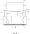
- FIG. 3 is another cross-sectional diagram of part of a system.
- Baffles 107 are disposed on the optic mount 103 and the base 107 on a side of the bellows 108 outside the actuator compartment 110.
- the baffles 107 on the optic mount 103 extend toward the base 106.
- the baffles 107 on the base 106 extend toward the optic mount 103.
- the baffles 107 can be positioned outside the bellows 108 to create a labyrinthine path for particles.
- Baffles 107 also can be positioned on the optic mount 103 and/or base 107 inside the actuator compartment 110. This can capture particles before they reach the filter assembly 111.
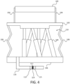
- FIG. 4 is another cross-sectional diagram of part of a system 100.
- a gas pathway 116 is disposed on the base 106.
- the gas pathway 116 is in fluid communication between the actuator compartment 110 and a vacuum chamber on the other side of the base 106.
- the filter assembly 111 is disposed in the gas pathway 116.
- the gas pathway 116 can be a pipe, duct, or conduit.
- the gas pathway 116 is illustrated as terminating under the base 106, but can be connected to a more remote location.
- the gas pathway 116 may terminate at a vacuum pump for the vacuum chamber 101, somewhere outside the vacuum chamber 101, or a separate vacuum pump for the actuator compartment 110.
- the base 106 may be mounted flat on a surface in the vacuum chamber 101.
- the gas pathway 116 can be formed through the surface that the vacuum chamber 101 is mounted on.
- FIG. 5 is a flowchart of a method 200.
- the method 200 can be used in a system, such as the system 100.
- An optical component is provided on an optic mount in a vacuum chamber at 201.
- An actuator disposed between the optic mount and a base also is provided at 201.
- a bellows is disposed between the base and the optic mount. The bellows, the base, and the optic mount define an actuator compartment therebetween. The bellows provides a seal between the base and the optic mount.
- Pressure is reduced in the vacuum chamber, which surrounds the optical component and bellows, with a vacuum pump at 202.
- the filter assembly includes a first filter, a purifier medium, and a second filter.
- the first filter and/or the second filter can be a mesh made of metal.
- the purifier medium can include at least one of activated carbon, a zeolite, a silica gel, or a polymer.
- the first filter and the second filter are a mesh made of metal, and the purifier medium includes activated carbon.
- the filter assembly can disposed in the base or in a gas pathway disposed on the base.
- the optic mount can be moved relative to the base using the actuator.
- a beam of EUV light can be directed through the vacuum chamber at the optical component.
- the embodiments disclosed herein also can protect the actuator from the environment outside the actuator compartment.
- solvents, plasma, O 3 , ultraviolet light, and/or H 2 may be used. These cleaning techniques can damage the actuator.
- the bellows and filter assembly can protect the actuator from these cleaning techniques.
Landscapes
- Physics & Mathematics (AREA)
- General Physics & Mathematics (AREA)
- Public Health (AREA)
- Epidemiology (AREA)
- Health & Medical Sciences (AREA)
- Engineering & Computer Science (AREA)
- Environmental & Geological Engineering (AREA)
- Life Sciences & Earth Sciences (AREA)
- Atmospheric Sciences (AREA)
- Analytical Chemistry (AREA)
- Chemical & Material Sciences (AREA)
- Optics & Photonics (AREA)
- Plasma & Fusion (AREA)
- Exposure And Positioning Against Photoresist Photosensitive Materials (AREA)
- Exposure Of Semiconductors, Excluding Electron Or Ion Beam Exposure (AREA)
- Investigating Materials By The Use Of Optical Means Adapted For Particular Applications (AREA)
- Mounting And Adjusting Of Optical Elements (AREA)
- Preparing Plates And Mask In Photomechanical Process (AREA)
- Testing Or Measuring Of Semiconductors Or The Like (AREA)
Applications Claiming Priority (3)
| Application Number | Priority Date | Filing Date | Title |
|---|---|---|---|
| US201962885798P | 2019-08-12 | 2019-08-12 | |
| US16/986,751 US11156926B2 (en) | 2019-08-12 | 2020-08-06 | Vacuum actuator containment for molecular contaminant and particle mitigation |
| PCT/US2020/045684 WO2021030302A1 (en) | 2019-08-12 | 2020-08-11 | Vacuum actuator containment for molecular contaminant and particle mitigation |
Publications (3)
| Publication Number | Publication Date |
|---|---|
| EP3987359A1 EP3987359A1 (en) | 2022-04-27 |
| EP3987359A4 EP3987359A4 (en) | 2023-07-05 |
| EP3987359B1 true EP3987359B1 (en) | 2025-05-14 |
Family
ID=74568359
Family Applications (1)
| Application Number | Title | Priority Date | Filing Date |
|---|---|---|---|
| EP20852600.4A Active EP3987359B1 (en) | 2019-08-12 | 2020-08-11 | Vacuum actuator containment for molecular contaminant and particle mitigation |
Country Status (7)
| Country | Link |
|---|---|
| US (1) | US11156926B2 (ko) |
| EP (1) | EP3987359B1 (ko) |
| JP (1) | JP7379661B2 (ko) |
| KR (1) | KR102615911B1 (ko) |
| CN (1) | CN114222950B (ko) |
| TW (1) | TWI843880B (ko) |
| WO (1) | WO2021030302A1 (ko) |
Families Citing this family (3)
| Publication number | Priority date | Publication date | Assignee | Title |
|---|---|---|---|---|
| DE102019213349A1 (de) * | 2019-09-03 | 2021-03-04 | Carl Zeiss Smt Gmbh | Spiegelanordnung mit Wasserstoff-Barriere und optische Anordnung |
| US12044701B2 (en) * | 2021-02-22 | 2024-07-23 | Kla Corporation | Vertical convolute metal bellows for rotary motion, vacuum sealing, and pressure sealing |
| US12444643B2 (en) * | 2021-10-18 | 2025-10-14 | Kla Corporation | Method and apparatus for positioning optical isolator assembly with replaceable motor assembly |
Family Cites Families (19)
| Publication number | Priority date | Publication date | Assignee | Title |
|---|---|---|---|---|
| JP3814207B2 (ja) * | 1995-06-13 | 2006-08-23 | 高砂熱学工業株式会社 | 清浄な資材用保管庫 |
| US6888362B2 (en) * | 2000-11-09 | 2005-05-03 | Formfactor, Inc. | Test head assembly for electronic components with plurality of contoured microelectronic spring contacts |
| US6279249B1 (en) | 1999-12-30 | 2001-08-28 | Intel Corporation | Reduced particle contamination manufacturing and packaging for reticles |
| CN100592213C (zh) * | 2002-02-22 | 2010-02-24 | Asml控股股份有限公司 | 使用两件式盖子保护模版的系统和方法 |
| JP4649136B2 (ja) * | 2003-07-31 | 2011-03-09 | キヤノン株式会社 | アクチュエータ、露光装置及びデバイス製造方法 |
| US7151589B2 (en) | 2004-06-24 | 2006-12-19 | Asml Netherlands B.V. | Lithographic apparatus and patterning device transport |
| US7030959B2 (en) * | 2004-07-23 | 2006-04-18 | Nikon Corporation | Extreme ultraviolet reticle protection using gas flow thermophoresis |
| JP4440031B2 (ja) | 2004-07-29 | 2010-03-24 | キヤノン株式会社 | 露光装置及びデバイス製造方法 |
| EP1744215B1 (en) * | 2005-07-16 | 2012-09-12 | Integrated Dynamics Engineering GmbH | Supporting device for supporting vibration sensitive components |
| DE102006044591A1 (de) * | 2006-09-19 | 2008-04-03 | Carl Zeiss Smt Ag | Optische Anordnung, insbesondere Projektionsbelichtungsanlage für die EUV-Lithographie, sowie reflektives optisches Element mit verminderter Kontamination |
| DE102007014940B3 (de) * | 2007-03-23 | 2008-10-16 | Siemens Ag | Vorrichtung zur Überwachung des Vakuums |
| US8625070B2 (en) * | 2007-11-15 | 2014-01-07 | Asml Holding N.V. | Lithographic apparatus, projection system and damper for use in a lithographic apparatus and device manufacturing method |
| NL1036785A1 (nl) * | 2008-04-18 | 2009-10-20 | Asml Netherlands Bv | Rapid exchange device for lithography reticles. |
| GB201017808D0 (en) * | 2010-10-21 | 2010-12-01 | Univ Salford The | An air spring |
| US20130235357A1 (en) | 2012-03-12 | 2013-09-12 | Kla-Tencor Corporation | System and Method for Particle Control Near A Reticle |
| US9851643B2 (en) | 2012-03-27 | 2017-12-26 | Kla-Tencor Corporation | Apparatus and methods for reticle handling in an EUV reticle inspection tool |
| US9268031B2 (en) | 2012-04-09 | 2016-02-23 | Kla-Tencor Corporation | Advanced debris mitigation of EUV light source |
| US9412632B2 (en) | 2012-10-25 | 2016-08-09 | Taiwan Semiconductor Manufacturing Company, Ltd. | Reticle pod |
| CN105900017B (zh) * | 2014-01-13 | 2019-04-23 | Asml荷兰有限公司 | 致动机构、光学装置和光刻装置 |
-
2020
- 2020-08-06 US US16/986,751 patent/US11156926B2/en active Active
- 2020-08-11 EP EP20852600.4A patent/EP3987359B1/en active Active
- 2020-08-11 WO PCT/US2020/045684 patent/WO2021030302A1/en not_active Ceased
- 2020-08-11 CN CN202080056686.XA patent/CN114222950B/zh active Active
- 2020-08-11 JP JP2022508578A patent/JP7379661B2/ja active Active
- 2020-08-11 KR KR1020227007611A patent/KR102615911B1/ko active Active
- 2020-08-12 TW TW109127318A patent/TWI843880B/zh active
Also Published As
| Publication number | Publication date |
|---|---|
| US11156926B2 (en) | 2021-10-26 |
| TWI843880B (zh) | 2024-06-01 |
| EP3987359A4 (en) | 2023-07-05 |
| TW202125086A (zh) | 2021-07-01 |
| EP3987359A1 (en) | 2022-04-27 |
| CN114222950A (zh) | 2022-03-22 |
| KR102615911B1 (ko) | 2023-12-19 |
| KR20220042446A (ko) | 2022-04-05 |
| CN114222950B (zh) | 2023-01-17 |
| JP2022544252A (ja) | 2022-10-17 |
| WO2021030302A1 (en) | 2021-02-18 |
| JP7379661B2 (ja) | 2023-11-14 |
| US20210048756A1 (en) | 2021-02-18 |
Similar Documents
| Publication | Publication Date | Title |
|---|---|---|
| EP3987359B1 (en) | Vacuum actuator containment for molecular contaminant and particle mitigation | |
| KR101056513B1 (ko) | 리소그래피 장치용 세정 장치 및 게터 | |
| KR101968675B1 (ko) | 리소그래피 장치 및 방법 | |
| KR101429440B1 (ko) | 극자외선을 사용하고 게터 물질을 포함하는 휘발성 유기 화합물 흡수 부재를 갖는 리소그래피 장치 | |
| JP5442716B2 (ja) | 真空内使用のためのロボット及びリソグラフィ装置 | |
| US6924492B2 (en) | Lithographic apparatus, device manufacturing method, and device manufactured thereby | |
| EP1708032A2 (en) | Lithographic device, device manufacturing method and device manufactured thereby | |
| KR102828301B1 (ko) | 회전 운동, 진공 밀봉, 및 압력 밀봉을 위한 수직 나선형 금속 벨루우즈 | |
| JP2009004647A (ja) | 真空容器と真空排気方法及びeuv露光装置 | |
| JP2002246289A (ja) | 洗浄方法、金属部材、露光装置 | |
| JP2003309064A (ja) | 露光装置の製造方法及び光学装置の製造方法、並びに露光装置及び光学装置 |
Legal Events
| Date | Code | Title | Description |
|---|---|---|---|
| STAA | Information on the status of an ep patent application or granted ep patent |
Free format text: STATUS: THE INTERNATIONAL PUBLICATION HAS BEEN MADE |
|
| PUAI | Public reference made under article 153(3) epc to a published international application that has entered the european phase |
Free format text: ORIGINAL CODE: 0009012 |
|
| STAA | Information on the status of an ep patent application or granted ep patent |
Free format text: STATUS: REQUEST FOR EXAMINATION WAS MADE |
|
| 17P | Request for examination filed |
Effective date: 20220118 |
|
| AK | Designated contracting states |
Kind code of ref document: A1 Designated state(s): AL AT BE BG CH CY CZ DE DK EE ES FI FR GB GR HR HU IE IS IT LI LT LU LV MC MK MT NL NO PL PT RO RS SE SI SK SM TR |
|
| DAV | Request for validation of the european patent (deleted) | ||
| DAX | Request for extension of the european patent (deleted) | ||
| A4 | Supplementary search report drawn up and despatched |
Effective date: 20230606 |
|
| RIC1 | Information provided on ipc code assigned before grant |
Ipc: G02B 21/26 20060101ALI20230531BHEP Ipc: G02B 21/00 20060101ALI20230531BHEP Ipc: G03F 1/84 20120101ALI20230531BHEP Ipc: G03F 7/20 20060101AFI20230531BHEP |
|
| P01 | Opt-out of the competence of the unified patent court (upc) registered |
Effective date: 20230526 |
|
| GRAP | Despatch of communication of intention to grant a patent |
Free format text: ORIGINAL CODE: EPIDOSNIGR1 |
|
| STAA | Information on the status of an ep patent application or granted ep patent |
Free format text: STATUS: GRANT OF PATENT IS INTENDED |
|
| INTG | Intention to grant announced |
Effective date: 20241206 |
|
| GRAS | Grant fee paid |
Free format text: ORIGINAL CODE: EPIDOSNIGR3 |
|
| GRAA | (expected) grant |
Free format text: ORIGINAL CODE: 0009210 |
|
| STAA | Information on the status of an ep patent application or granted ep patent |
Free format text: STATUS: THE PATENT HAS BEEN GRANTED |
|
| AK | Designated contracting states |
Kind code of ref document: B1 Designated state(s): AL AT BE BG CH CY CZ DE DK EE ES FI FR GB GR HR HU IE IS IT LI LT LU LV MC MK MT NL NO PL PT RO RS SE SI SK SM TR |
|
| REG | Reference to a national code |
Ref country code: GB Ref legal event code: FG4D |
|
| REG | Reference to a national code |
Ref country code: CH Ref legal event code: EP |
|
| REG | Reference to a national code |
Ref country code: IE Ref legal event code: FG4D |
|
| REG | Reference to a national code |
Ref country code: DE Ref legal event code: R096 Ref document number: 602020051383 Country of ref document: DE |
|
| REG | Reference to a national code |
Ref country code: NL Ref legal event code: FP |
|
| PGFP | Annual fee paid to national office [announced via postgrant information from national office to epo] |
Ref country code: NL Payment date: 20250826 Year of fee payment: 6 |
|
| PG25 | Lapsed in a contracting state [announced via postgrant information from national office to epo] |
Ref country code: FI Free format text: LAPSE BECAUSE OF FAILURE TO SUBMIT A TRANSLATION OF THE DESCRIPTION OR TO PAY THE FEE WITHIN THE PRESCRIBED TIME-LIMIT Effective date: 20250514 Ref country code: PT Free format text: LAPSE BECAUSE OF FAILURE TO SUBMIT A TRANSLATION OF THE DESCRIPTION OR TO PAY THE FEE WITHIN THE PRESCRIBED TIME-LIMIT Effective date: 20250915 Ref country code: ES Free format text: LAPSE BECAUSE OF FAILURE TO SUBMIT A TRANSLATION OF THE DESCRIPTION OR TO PAY THE FEE WITHIN THE PRESCRIBED TIME-LIMIT Effective date: 20250514 |
|
| PGFP | Annual fee paid to national office [announced via postgrant information from national office to epo] |
Ref country code: DE Payment date: 20250827 Year of fee payment: 6 |
|
| REG | Reference to a national code |
Ref country code: LT Ref legal event code: MG9D |
|
| PG25 | Lapsed in a contracting state [announced via postgrant information from national office to epo] |
Ref country code: GR Free format text: LAPSE BECAUSE OF FAILURE TO SUBMIT A TRANSLATION OF THE DESCRIPTION OR TO PAY THE FEE WITHIN THE PRESCRIBED TIME-LIMIT Effective date: 20250815 Ref country code: NO Free format text: LAPSE BECAUSE OF FAILURE TO SUBMIT A TRANSLATION OF THE DESCRIPTION OR TO PAY THE FEE WITHIN THE PRESCRIBED TIME-LIMIT Effective date: 20250814 |
|
| PG25 | Lapsed in a contracting state [announced via postgrant information from national office to epo] |
Ref country code: PL Free format text: LAPSE BECAUSE OF FAILURE TO SUBMIT A TRANSLATION OF THE DESCRIPTION OR TO PAY THE FEE WITHIN THE PRESCRIBED TIME-LIMIT Effective date: 20250514 |
|
| REG | Reference to a national code |
Ref country code: AT Ref legal event code: MK05 Ref document number: 1795294 Country of ref document: AT Kind code of ref document: T Effective date: 20250514 |
|
| PG25 | Lapsed in a contracting state [announced via postgrant information from national office to epo] |
Ref country code: BG Free format text: LAPSE BECAUSE OF FAILURE TO SUBMIT A TRANSLATION OF THE DESCRIPTION OR TO PAY THE FEE WITHIN THE PRESCRIBED TIME-LIMIT Effective date: 20250514 |
|
| PG25 | Lapsed in a contracting state [announced via postgrant information from national office to epo] |
Ref country code: HR Free format text: LAPSE BECAUSE OF FAILURE TO SUBMIT A TRANSLATION OF THE DESCRIPTION OR TO PAY THE FEE WITHIN THE PRESCRIBED TIME-LIMIT Effective date: 20250514 |
|
| PG25 | Lapsed in a contracting state [announced via postgrant information from national office to epo] |
Ref country code: AT Free format text: LAPSE BECAUSE OF FAILURE TO SUBMIT A TRANSLATION OF THE DESCRIPTION OR TO PAY THE FEE WITHIN THE PRESCRIBED TIME-LIMIT Effective date: 20250514 |
|
| PG25 | Lapsed in a contracting state [announced via postgrant information from national office to epo] |
Ref country code: RS Free format text: LAPSE BECAUSE OF FAILURE TO SUBMIT A TRANSLATION OF THE DESCRIPTION OR TO PAY THE FEE WITHIN THE PRESCRIBED TIME-LIMIT Effective date: 20250814 |
|
| PG25 | Lapsed in a contracting state [announced via postgrant information from national office to epo] |
Ref country code: IS Free format text: LAPSE BECAUSE OF FAILURE TO SUBMIT A TRANSLATION OF THE DESCRIPTION OR TO PAY THE FEE WITHIN THE PRESCRIBED TIME-LIMIT Effective date: 20250914 |
|
| PG25 | Lapsed in a contracting state [announced via postgrant information from national office to epo] |
Ref country code: LV Free format text: LAPSE BECAUSE OF FAILURE TO SUBMIT A TRANSLATION OF THE DESCRIPTION OR TO PAY THE FEE WITHIN THE PRESCRIBED TIME-LIMIT Effective date: 20250514 |
|
| PG25 | Lapsed in a contracting state [announced via postgrant information from national office to epo] |
Ref country code: DK Free format text: LAPSE BECAUSE OF FAILURE TO SUBMIT A TRANSLATION OF THE DESCRIPTION OR TO PAY THE FEE WITHIN THE PRESCRIBED TIME-LIMIT Effective date: 20250514 Ref country code: SM Free format text: LAPSE BECAUSE OF FAILURE TO SUBMIT A TRANSLATION OF THE DESCRIPTION OR TO PAY THE FEE WITHIN THE PRESCRIBED TIME-LIMIT Effective date: 20250514 |
|
| PG25 | Lapsed in a contracting state [announced via postgrant information from national office to epo] |
Ref country code: CZ Free format text: LAPSE BECAUSE OF FAILURE TO SUBMIT A TRANSLATION OF THE DESCRIPTION OR TO PAY THE FEE WITHIN THE PRESCRIBED TIME-LIMIT Effective date: 20250514 |
|
| PG25 | Lapsed in a contracting state [announced via postgrant information from national office to epo] |
Ref country code: EE Free format text: LAPSE BECAUSE OF FAILURE TO SUBMIT A TRANSLATION OF THE DESCRIPTION OR TO PAY THE FEE WITHIN THE PRESCRIBED TIME-LIMIT Effective date: 20250514 |
|
| PG25 | Lapsed in a contracting state [announced via postgrant information from national office to epo] |
Ref country code: SK Free format text: LAPSE BECAUSE OF FAILURE TO SUBMIT A TRANSLATION OF THE DESCRIPTION OR TO PAY THE FEE WITHIN THE PRESCRIBED TIME-LIMIT Effective date: 20250514 Ref country code: RO Free format text: LAPSE BECAUSE OF FAILURE TO SUBMIT A TRANSLATION OF THE DESCRIPTION OR TO PAY THE FEE WITHIN THE PRESCRIBED TIME-LIMIT Effective date: 20250514 |
|
| PG25 | Lapsed in a contracting state [announced via postgrant information from national office to epo] |
Ref country code: IT Free format text: LAPSE BECAUSE OF FAILURE TO SUBMIT A TRANSLATION OF THE DESCRIPTION OR TO PAY THE FEE WITHIN THE PRESCRIBED TIME-LIMIT Effective date: 20250514 |