EP3986765B1 - System zur kühlung technischer einrichtungen in einem schienenfahrzeug - Google Patents
System zur kühlung technischer einrichtungen in einem schienenfahrzeug Download PDFInfo
- Publication number
- EP3986765B1 EP3986765B1 EP20754669.8A EP20754669A EP3986765B1 EP 3986765 B1 EP3986765 B1 EP 3986765B1 EP 20754669 A EP20754669 A EP 20754669A EP 3986765 B1 EP3986765 B1 EP 3986765B1
- Authority
- EP
- European Patent Office
- Prior art keywords
- cooling
- chambers
- air
- flaps
- rail vehicle
- Prior art date
- Legal status (The legal status is an assumption and is not a legal conclusion. Google has not performed a legal analysis and makes no representation as to the accuracy of the status listed.)
- Active
Links
Images

Classifications
-
- B—PERFORMING OPERATIONS; TRANSPORTING
- B61—RAILWAYS
- B61C—LOCOMOTIVES; MOTOR RAILCARS
- B61C5/00—Locomotives or motor railcars with IC engines or gas turbines
- B61C5/02—Arrangement or disposition of intakes and apparatus for supplying, circulating, and filtering air for combustion and engine-cooling purposes
-
- B—PERFORMING OPERATIONS; TRANSPORTING
- B61—RAILWAYS
- B61D—BODY DETAILS OR KINDS OF RAILWAY VEHICLES
- B61D27/00—Heating, cooling, ventilating, or air-conditioning
- B61D27/0072—Means for cooling only
-
- B—PERFORMING OPERATIONS; TRANSPORTING
- B61—RAILWAYS
- B61C—LOCOMOTIVES; MOTOR RAILCARS
- B61C17/00—Arrangement or disposition of parts; Details or accessories not otherwise provided for; Use of control gear and control systems
- B61C17/04—Arrangement or disposition of driving cabins, footplates or engine rooms; Ventilation thereof
-
- Y—GENERAL TAGGING OF NEW TECHNOLOGICAL DEVELOPMENTS; GENERAL TAGGING OF CROSS-SECTIONAL TECHNOLOGIES SPANNING OVER SEVERAL SECTIONS OF THE IPC; TECHNICAL SUBJECTS COVERED BY FORMER USPC CROSS-REFERENCE ART COLLECTIONS [XRACs] AND DIGESTS
- Y02—TECHNOLOGIES OR APPLICATIONS FOR MITIGATION OR ADAPTATION AGAINST CLIMATE CHANGE
- Y02T—CLIMATE CHANGE MITIGATION TECHNOLOGIES RELATED TO TRANSPORTATION
- Y02T30/00—Transportation of goods or passengers via railways, e.g. energy recovery or reducing air resistance
Definitions
- the invention relates to a system for cooling technical equipment in a rail vehicle.
- Rail vehicles are equipped with a large number of technical devices which emit waste heat during operation.
- Larger devices such as air conditioning systems, drive power electronics, converters, air compressors, etc. are usually combined into assemblies with a specific function as a so-called "underfloor container” and arranged below the underframe or on the roof.
- These containers are self-contained housings and usually include forced ventilation with air inlets and outlets and fans.
- the arrangement of these containers, in particular below the underframe can mean that the exhaust air from one container is at least partially sucked in as supply air from another container. This reduces the cooling of the equipment located in the affected container, which can lead to a reduced service life or at least shutdown due to overheating.
- a cooling device for electrical systems in a rail vehicle in which a central air inlet is provided, via which cooling air is introduced into the interior of the car and devices to be cooled are arranged in chambers and cooled air flows around them. The heated exhaust air is sucked off by means of a fan and discharged to the environment via a central air outlet.
- a device for cooling underfloor devices can the patent application EP794098A1 be removed. This discloses assigning specific chambers to individual drive components, such as power converters, and cooling these chambers with a common fan.
- the invention is therefore based on the object of specifying a system for cooling technical devices in a rail vehicle, which system is able to cool a number of technical devices without mutual repercussions, in which case, in particular, a low energy consumption for cooling should be achieved.
- a system for cooling technical equipment in a rail vehicle which comprises a container assembly with a plurality of chambers, each technical equipment being arranged in a chamber assigned to it, which each comprises at least one air inlet opening and at least one exhaust air opening, wherein at least one fan for forced ventilation of the chambers and air ducts between the fans and the chambers are provided, and the chambers are equipped with force-actuable control flaps in their respective cooling air flow.
- the advantage can be achieved of being able to supply all technical devices arranged in the system with cooling air simultaneously by means of a central fan and being able to continuously adapt the cooling air flow to the current power loss of each technical device.
- a system for cooling technical equipment in a rail vehicle includes a container assembly with multiple chambers.
- This container assembly can be constructed, for example, as an underfloor container for a rail vehicle, but its dimensions can be dimensioned such that all the technical equipment that is typically arranged in individual underfloor equipment carriers can be accommodated in this container assembly.
- Each technical device is a chamber in the container assembly assigned.
- the system also includes at least one fan, which generates a flow of cooling air centrally and directs it to the individual chambers via air ducts.
- the air ducts ensure low-resistance routing of the cooling air between the fan and the chambers.
- the chambers are each equipped with at least one supply air opening and one exhaust air opening each and each have at least one power-actuable control flap.
- control flaps are arranged in the cooling air flow and can modulate it, ie change its volume flow.
- the cooling air flow can be continuously modulated or switched on and off.
- the control flaps can be driven by means of an electric actuator or by means of a pneumatic drive. The latter is particularly advantageous if stepless control of the control flaps is not required.
- the fan can be designed as a single fan in a radial or axial design and is preferably controllable in terms of its speed.
- a major advantage of a larger, common fan for all technical equipment in a system is the reduced noise emission compared to a number of smaller individual fans.
- a large fan can usually be operated more energy-efficiently than several small fans.
- the flow direction of the cooling air flow is important for the function of the invention regardless, the fan may be arranged to draw ambient air into the chambers or to extract heated air from the chambers.
- Another advantage of this central ventilation concept is that with a redundant design of two central fans, the reliability is significantly higher than with, for example, four separate containers, each with their own fans.
- a preferred embodiment of the invention envisages using the chambers each with a temperature sensor for measuring the temperature prevailing in the respective chamber and transmitting the temperature values determined in this way to a control device.
- This control device includes means for controlling the power drives of the control flaps and optionally also means for controlling the entire flow of cooling air by changing the speed of the fan. These means typically include suitable power electronics for electric drives or pneumatic valves in the case of control flaps operated by compressed air. From the temperature values determined in the individual chambers, the control device determines the required position of the control flaps in each chamber and, if applicable, the required volume flow of the fan and sets these values on the control flaps and the fan. In this way, if there is a brief increase in the cooling requirement of a technical device (e.g. a drive converter during a longer acceleration phase), the cooling air can be diverted to this device and a device without an increased cooling requirement (e.g. an air conditioning system not in operation) can be separated from the cooling air supply during this time.
- a technical device e.g.
- thermosensitive technical equipment e.g. power electronics
- less sensitive ones e.g. braking resistors
- a preferred embodiment of the invention provides for connecting flaps to be provided between adjacent chambers of the container assembly, which allow air to be exchanged directly between these chambers.
- these connecting flaps can be moved with the assistance of a force, the position of the connecting flaps being specified by the control device.
- a more extensive flexibility of the air flow in the container assembly can be achieved, for example in order to cover a short-term increased cooling air requirement of an individual technical device in addition to its inlet opening via neighboring chambers.
- the system can be operated even more energy-efficiently thanks to the additional possibility of temperature-dependent serial flow through adjacent chambers.
- the direction in which the cooling air is blown out can also be specified flexibly in accordance with the current requirement.
- hot exhaust air can be avoided in the direction of the passengers, in particular through the gap between a platform and the car body.
- fan flaps are to be provided, which can close the cooling air outlet that is open while driving. At the same time other flaps are to be opened, which allow the exhaust air to flow out at less critical points, for example in the subframe in the axial direction towards the bogies.
- the present system for cooling technical equipment in a rail vehicle is constructed as a container assembly, which can be arranged in the usual way under the underframe or on the roof of a rail vehicle. In this way, since there is no need to assemble several separate underfloor containers, the final assembly of the rail vehicle can be accelerated, and by controlling the amount of cooling air, energy for driving the fan can be saved.
- Fig.1 shows a rail vehicle with an underfloor container as an example and schematically. It is the view of the underside of a rail vehicle 1 with underfloor containers 2 after State of the art shown.
- four underfloor containers 2 are arranged on the underside, which are each assigned a function, ie a type of technical device.
- Each of the underfloor containers includes a cooling device, each with a fan, and blows the heated cooling air out in a specific direction.
- the two centrally located underfloor containers 2 are disadvantaged, since the blowing out of their cooling air from another underfloor container 2 is impeded.
- Fig.2 shows a rail vehicle with a cooling system by way of example and schematically. It shows the view of the underside of a rail vehicle 1 with a system according to the invention for cooling technical equipment.
- a container assembly 3 is arranged on the underside of the rail vehicle 1 , which includes four chambers 4 .
- a technical device 5 is arranged in each of these chambers 4 .
- a fan 6 is arranged in the container assembly 3 in such a way that the cooling air it moves is guided to and from the chambers 4 by means of air guiding devices 7 .
- the direction of flow of the cooling air is irrelevant here; the fan 6 can convey the cooling air to the chambers 4 or suck it out of them.
- the chambers 4 each have a supply air opening and an exhaust air opening, one of the openings being equipped with a control valve 8, by means of which the flow of cooling air through the respective chamber 4 can be regulated or prevented.
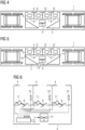
- Fig.3 shows a schematic example of a rail vehicle with a longitudinal flow cooling system. It is a rail vehicle 1, similar to that in 2 illustrated embodiment shown, wherein the Arrangement of the chambers 4 is designed so that the cooling air is transported to both sides of the rail vehicle 1, so the cooling air is blown out on both sides and sucked in axially, or sucked in on both sides and blown out axially.
- Fig.4 shows an example and diagrammatically of a rail vehicle with a cooling system with connecting flaps. It is the embodiment from 2 shown, with additional connection flaps 12 are arranged between adjacent chambers 4, so that the cooling air can be exchanged directly between adjacent chambers 4.
- additional, controllable flow paths enable increased flexibility in controlling the cooling effect.
- a technical device 5 can obtain additional cooling air through the adjacent chambers 4 for a short time when there is an increased cooling requirement.
- Fig.5 shows a schematic example of a rail vehicle with a cooling system and side-selective blow-out. It is the embodiment from 4 shown, with a ventilation flap 13 also being provided, through which the cooling air can be discharged transversely to the direction of travel of the rail vehicle 1 .
- This louver 13 is arranged near a side wall.
- two axial flaps 14 are provided, through which the cooling air can be discharged along the direction of travel of the rail vehicle 1, in the region of the bogies.
- the flaps 13 and 14 are designed in such a way that they are able to interrupt the flow of air through them.
- the position of the cooling air discharge can be changed, for example on the open route discharge via the fan flap 13 and at a stop in a train station discharge via the Axial flaps 14 takes place.
- the passengers can be protected from a hot jet of exhaust air.
- the switchover of the position of the exhaust air outlet can be coupled with a door control, for example, so that when the door opens, the exhaust air is directed in the direction of the bogies.
- FIG.6 shows a container assembly by way of example and diagrammatically.
- a container assembly 3 is shown in highly abstract form, which includes three chambers 4 and a fan 6 .
- Each of the chambers 4 is provided with a power operated control flap 8 which is movable by a power actuator 11 between an open and a closed position.
- a temperature sensor 10 is also arranged in each chamber 4 .
- a control device 9 is equipped with the resources required to operate the fan 6 , for example power electronics for controlling the speed of the fan 6 .
- the power drives 11 of the control flaps 8 are connected to the control device 9 and can be controlled by it.
- the output signals of the temperature sensors 10 are routed to the control device 9 so that the latter specifies the position of the control flaps 8 and the speed of the fan 6 as a function of the respective temperature in the chambers 4 .
Landscapes
- Engineering & Computer Science (AREA)
- Mechanical Engineering (AREA)
- Transportation (AREA)
- Chemical & Material Sciences (AREA)
- Combustion & Propulsion (AREA)
- Automation & Control Theory (AREA)
- Cooling, Air Intake And Gas Exhaust, And Fuel Tank Arrangements In Propulsion Units (AREA)
- Cooling Or The Like Of Electrical Apparatus (AREA)
- Devices That Are Associated With Refrigeration Equipment (AREA)
Applications Claiming Priority (2)
| Application Number | Priority Date | Filing Date | Title |
|---|---|---|---|
| ATA50717/2019A AT522866B1 (de) | 2019-08-14 | 2019-08-14 | System zur Kühlung technischer Einrichtungen in einem Schienenfahrzeug |
| PCT/EP2020/071477 WO2021028229A1 (de) | 2019-08-14 | 2020-07-30 | System zur kühlung technischer einrichtungen in einem schienenfahrzeug |
Publications (2)
| Publication Number | Publication Date |
|---|---|
| EP3986765A1 EP3986765A1 (de) | 2022-04-27 |
| EP3986765B1 true EP3986765B1 (de) | 2023-03-01 |
Family
ID=72050819
Family Applications (1)
| Application Number | Title | Priority Date | Filing Date |
|---|---|---|---|
| EP20754669.8A Active EP3986765B1 (de) | 2019-08-14 | 2020-07-30 | System zur kühlung technischer einrichtungen in einem schienenfahrzeug |
Country Status (6)
| Country | Link |
|---|---|
| EP (1) | EP3986765B1 (pl) |
| CN (1) | CN218033876U (pl) |
| AT (1) | AT522866B1 (pl) |
| ES (1) | ES2940223T3 (pl) |
| PL (1) | PL3986765T3 (pl) |
| WO (1) | WO2021028229A1 (pl) |
Family Cites Families (7)
| Publication number | Priority date | Publication date | Assignee | Title |
|---|---|---|---|---|
| JPH04193670A (ja) * | 1990-11-28 | 1992-07-13 | Hitachi Ltd | 車両用電気機器の冷却構造 |
| FR2703967B1 (fr) * | 1993-04-15 | 1995-05-19 | Gec Alsthom Transport Sa | Circuit de ventilation de composants électriques pour véhicule de traction ferroviaire. |
| JPH09246767A (ja) * | 1996-03-05 | 1997-09-19 | Hitachi Ltd | 電気車用電力変換装置 |
| DE19811719A1 (de) * | 1998-03-18 | 1999-09-23 | Alstom Lhb Gmbh | Kühleinrichtung zum Kühlen von Schaltschränken oder Bauteilen in Schienenfahrzeugen |
| DE19951356A1 (de) * | 1999-10-26 | 2001-05-03 | Daimler Chrysler Ag | Unterflurcontainer für Schienenfahrzeuge |
| JP3715515B2 (ja) * | 2000-07-19 | 2005-11-09 | 東芝トランスポートエンジニアリング株式会社 | 車両用制御装置 |
| DE102016109900A1 (de) * | 2016-05-30 | 2017-11-30 | Bombardier Transportation Gmbh | Kühlvorrichtung für ein Fahrzeug |
-
2019
- 2019-08-14 AT ATA50717/2019A patent/AT522866B1/de not_active IP Right Cessation
-
2020
- 2020-07-30 CN CN202090000811.0U patent/CN218033876U/zh active Active
- 2020-07-30 EP EP20754669.8A patent/EP3986765B1/de active Active
- 2020-07-30 WO PCT/EP2020/071477 patent/WO2021028229A1/de not_active Ceased
- 2020-07-30 ES ES20754669T patent/ES2940223T3/es active Active
- 2020-07-30 PL PL20754669.8T patent/PL3986765T3/pl unknown
Also Published As
| Publication number | Publication date |
|---|---|
| WO2021028229A1 (de) | 2021-02-18 |
| AT522866A1 (de) | 2021-02-15 |
| ES2940223T3 (es) | 2023-05-04 |
| CN218033876U (zh) | 2022-12-13 |
| PL3986765T3 (pl) | 2023-07-17 |
| EP3986765A1 (de) | 2022-04-27 |
| AT522866B1 (de) | 2022-05-15 |
Similar Documents
| Publication | Publication Date | Title |
|---|---|---|
| EP2356026B1 (de) | Notenergiesystem für ein luftfahrzeug | |
| EP3647198B1 (de) | Flugzeugkälteanlage mit einer motor-unterstützten kabinenabluftturbine | |
| DE102008020310B4 (de) | Kraftfahrzeug mit zwei Wärmetauschern | |
| EP2668078B1 (de) | Kühlung von einrichtungen eines schienenfahrzeugs | |
| EP1078854A1 (de) | Vorrichtung zur Klimatisierung von Passagierflugzeugen | |
| DE102013008620A1 (de) | Flugzeugkühlsystem und Verfahren zum Betreiben eines Flugzeugkühlsystems | |
| EP0943520B1 (de) | Kühleinrichtung zum Kühlen von Schaltschränken oder Bauteilen in Schienenfahrzeugen | |
| EP2127991B2 (de) | Lokomotive | |
| EP3490824B1 (de) | Klimatisierungsvorrichtung für ein kraftfahrzeug | |
| EP3740407B1 (de) | Unterflurgeräteträger für ein schienenfahrzeug | |
| EP3986765B1 (de) | System zur kühlung technischer einrichtungen in einem schienenfahrzeug | |
| DE4223647C2 (de) | Vorrichtung zur Kühlung von elektronischen Einheiten einer Energieversorgungsanlage für Reisezugwagen | |
| EP0212306A2 (de) | Heiz- und Belüftungseinrichtung für Kraftfahrzeuge | |
| EP2337696B1 (de) | Klimatisierungsanordnung | |
| EP2560858B1 (de) | Anordnung zur temperierung von elektrischen komponenten in einem fahrzeug | |
| DE102015207442A1 (de) | Fahrzeug mit einer zu kühlenden Fahrzeugkomponente | |
| DE102011113654A1 (de) | Vorrichtung und Verfahren zum Kühlen elektrischer Fahrmotoren | |
| WO2016041549A1 (de) | Vorrichtung für eine kombinierte druckschutz- und luftmengenregelung im innenraum von hochgeschwindigkeits-schienenfahrzeugen | |
| DE202018104361U1 (de) | Schließeinrichtung mit klappenförmigen Bauelementen für Ansaug- bzw. Ausblasöffnungen der Prozessluft von Klima- und Lüftungsgeräten für Schienenfahrzeuge | |
| DE855275C (de) | Lueftungs- und Filtrieranlage eines Schienentriebfahrzeuges mit Brennkraftmaschine und elektrischer Kraftuebertragung | |
| DE202018104362U1 (de) | Schließeinrichtung mit Lamellen für Ansaug- bzw. Ausblasöffnungen der Prozessluft von Klima- und Lüftungsgeräten für Schienenfahrzeuge | |
| EP3442844B1 (de) | Luftverteileinrichtung für ein fahrzeug | |
| DE9408362U1 (de) | Dachentlüftungsanordnung für Elektronikschränke | |
| WO1995018944A1 (de) | Klima-gerät mit redundantventilator | |
| EP3921194B1 (de) | Kühlgerät für ein fahrzeug, fahrzeug und verfahren zum betreiben eines kühlgeräts |
Legal Events
| Date | Code | Title | Description |
|---|---|---|---|
| STAA | Information on the status of an ep patent application or granted ep patent |
Free format text: STATUS: UNKNOWN |
|
| STAA | Information on the status of an ep patent application or granted ep patent |
Free format text: STATUS: THE INTERNATIONAL PUBLICATION HAS BEEN MADE |
|
| PUAI | Public reference made under article 153(3) epc to a published international application that has entered the european phase |
Free format text: ORIGINAL CODE: 0009012 |
|
| STAA | Information on the status of an ep patent application or granted ep patent |
Free format text: STATUS: REQUEST FOR EXAMINATION WAS MADE |
|
| 17P | Request for examination filed |
Effective date: 20220118 |
|
| AK | Designated contracting states |
Kind code of ref document: A1 Designated state(s): AL AT BE BG CH CY CZ DE DK EE ES FI FR GB GR HR HU IE IS IT LI LT LU LV MC MK MT NL NO PL PT RO RS SE SI SK SM TR |
|
| GRAP | Despatch of communication of intention to grant a patent |
Free format text: ORIGINAL CODE: EPIDOSNIGR1 |
|
| STAA | Information on the status of an ep patent application or granted ep patent |
Free format text: STATUS: GRANT OF PATENT IS INTENDED |
|
| DAV | Request for validation of the european patent (deleted) | ||
| DAX | Request for extension of the european patent (deleted) | ||
| INTG | Intention to grant announced |
Effective date: 20221026 |
|
| GRAS | Grant fee paid |
Free format text: ORIGINAL CODE: EPIDOSNIGR3 |
|
| GRAA | (expected) grant |
Free format text: ORIGINAL CODE: 0009210 |
|
| STAA | Information on the status of an ep patent application or granted ep patent |
Free format text: STATUS: THE PATENT HAS BEEN GRANTED |
|
| AK | Designated contracting states |
Kind code of ref document: B1 Designated state(s): AL AT BE BG CH CY CZ DE DK EE ES FI FR GB GR HR HU IE IS IT LI LT LU LV MC MK MT NL NO PL PT RO RS SE SI SK SM TR |
|
| REG | Reference to a national code |
Ref country code: GB Ref legal event code: FG4D Free format text: NOT ENGLISH |
|
| REG | Reference to a national code |
Ref country code: CH Ref legal event code: EP Ref country code: AT Ref legal event code: REF Ref document number: 1550773 Country of ref document: AT Kind code of ref document: T Effective date: 20230315 |
|
| REG | Reference to a national code |
Ref country code: DE Ref legal event code: R096 Ref document number: 502020002646 Country of ref document: DE |
|
| REG | Reference to a national code |
Ref country code: IE Ref legal event code: FG4D Free format text: LANGUAGE OF EP DOCUMENT: GERMAN |
|
| REG | Reference to a national code |
Ref country code: ES Ref legal event code: FG2A Ref document number: 2940223 Country of ref document: ES Kind code of ref document: T3 Effective date: 20230504 |
|
| REG | Reference to a national code |
Ref country code: LT Ref legal event code: MG9D |
|
| REG | Reference to a national code |
Ref country code: NL Ref legal event code: MP Effective date: 20230301 |
|
| PG25 | Lapsed in a contracting state [announced via postgrant information from national office to epo] |
Ref country code: RS Free format text: LAPSE BECAUSE OF FAILURE TO SUBMIT A TRANSLATION OF THE DESCRIPTION OR TO PAY THE FEE WITHIN THE PRESCRIBED TIME-LIMIT Effective date: 20230301 Ref country code: NO Free format text: LAPSE BECAUSE OF FAILURE TO SUBMIT A TRANSLATION OF THE DESCRIPTION OR TO PAY THE FEE WITHIN THE PRESCRIBED TIME-LIMIT Effective date: 20230601 Ref country code: LV Free format text: LAPSE BECAUSE OF FAILURE TO SUBMIT A TRANSLATION OF THE DESCRIPTION OR TO PAY THE FEE WITHIN THE PRESCRIBED TIME-LIMIT Effective date: 20230301 Ref country code: LT Free format text: LAPSE BECAUSE OF FAILURE TO SUBMIT A TRANSLATION OF THE DESCRIPTION OR TO PAY THE FEE WITHIN THE PRESCRIBED TIME-LIMIT Effective date: 20230301 Ref country code: HR Free format text: LAPSE BECAUSE OF FAILURE TO SUBMIT A TRANSLATION OF THE DESCRIPTION OR TO PAY THE FEE WITHIN THE PRESCRIBED TIME-LIMIT Effective date: 20230301 |
|
| PG25 | Lapsed in a contracting state [announced via postgrant information from national office to epo] |
Ref country code: SE Free format text: LAPSE BECAUSE OF FAILURE TO SUBMIT A TRANSLATION OF THE DESCRIPTION OR TO PAY THE FEE WITHIN THE PRESCRIBED TIME-LIMIT Effective date: 20230301 Ref country code: NL Free format text: LAPSE BECAUSE OF FAILURE TO SUBMIT A TRANSLATION OF THE DESCRIPTION OR TO PAY THE FEE WITHIN THE PRESCRIBED TIME-LIMIT Effective date: 20230301 Ref country code: GR Free format text: LAPSE BECAUSE OF FAILURE TO SUBMIT A TRANSLATION OF THE DESCRIPTION OR TO PAY THE FEE WITHIN THE PRESCRIBED TIME-LIMIT Effective date: 20230602 Ref country code: FI Free format text: LAPSE BECAUSE OF FAILURE TO SUBMIT A TRANSLATION OF THE DESCRIPTION OR TO PAY THE FEE WITHIN THE PRESCRIBED TIME-LIMIT Effective date: 20230301 |
|
| PG25 | Lapsed in a contracting state [announced via postgrant information from national office to epo] |
Ref country code: SM Free format text: LAPSE BECAUSE OF FAILURE TO SUBMIT A TRANSLATION OF THE DESCRIPTION OR TO PAY THE FEE WITHIN THE PRESCRIBED TIME-LIMIT Effective date: 20230301 Ref country code: RO Free format text: LAPSE BECAUSE OF FAILURE TO SUBMIT A TRANSLATION OF THE DESCRIPTION OR TO PAY THE FEE WITHIN THE PRESCRIBED TIME-LIMIT Effective date: 20230301 Ref country code: PT Free format text: LAPSE BECAUSE OF FAILURE TO SUBMIT A TRANSLATION OF THE DESCRIPTION OR TO PAY THE FEE WITHIN THE PRESCRIBED TIME-LIMIT Effective date: 20230703 Ref country code: EE Free format text: LAPSE BECAUSE OF FAILURE TO SUBMIT A TRANSLATION OF THE DESCRIPTION OR TO PAY THE FEE WITHIN THE PRESCRIBED TIME-LIMIT Effective date: 20230301 |
|
| PG25 | Lapsed in a contracting state [announced via postgrant information from national office to epo] |
Ref country code: SK Free format text: LAPSE BECAUSE OF FAILURE TO SUBMIT A TRANSLATION OF THE DESCRIPTION OR TO PAY THE FEE WITHIN THE PRESCRIBED TIME-LIMIT Effective date: 20230301 Ref country code: IS Free format text: LAPSE BECAUSE OF FAILURE TO SUBMIT A TRANSLATION OF THE DESCRIPTION OR TO PAY THE FEE WITHIN THE PRESCRIBED TIME-LIMIT Effective date: 20230701 |
|
| REG | Reference to a national code |
Ref country code: DE Ref legal event code: R097 Ref document number: 502020002646 Country of ref document: DE |
|
| PLBE | No opposition filed within time limit |
Free format text: ORIGINAL CODE: 0009261 |
|
| STAA | Information on the status of an ep patent application or granted ep patent |
Free format text: STATUS: NO OPPOSITION FILED WITHIN TIME LIMIT |
|
| PG25 | Lapsed in a contracting state [announced via postgrant information from national office to epo] |
Ref country code: SI Free format text: LAPSE BECAUSE OF FAILURE TO SUBMIT A TRANSLATION OF THE DESCRIPTION OR TO PAY THE FEE WITHIN THE PRESCRIBED TIME-LIMIT Effective date: 20230301 Ref country code: DK Free format text: LAPSE BECAUSE OF FAILURE TO SUBMIT A TRANSLATION OF THE DESCRIPTION OR TO PAY THE FEE WITHIN THE PRESCRIBED TIME-LIMIT Effective date: 20230301 |
|
| 26N | No opposition filed |
Effective date: 20231204 |
|
| PG25 | Lapsed in a contracting state [announced via postgrant information from national office to epo] |
Ref country code: MC Free format text: LAPSE BECAUSE OF FAILURE TO SUBMIT A TRANSLATION OF THE DESCRIPTION OR TO PAY THE FEE WITHIN THE PRESCRIBED TIME-LIMIT Effective date: 20230301 |
|
| PG25 | Lapsed in a contracting state [announced via postgrant information from national office to epo] |
Ref country code: MC Free format text: LAPSE BECAUSE OF FAILURE TO SUBMIT A TRANSLATION OF THE DESCRIPTION OR TO PAY THE FEE WITHIN THE PRESCRIBED TIME-LIMIT Effective date: 20230301 |
|
| REG | Reference to a national code |
Ref country code: BE Ref legal event code: MM Effective date: 20230731 |
|
| PG25 | Lapsed in a contracting state [announced via postgrant information from national office to epo] |
Ref country code: LU Free format text: LAPSE BECAUSE OF NON-PAYMENT OF DUE FEES Effective date: 20230730 |
|
| PG25 | Lapsed in a contracting state [announced via postgrant information from national office to epo] |
Ref country code: LU Free format text: LAPSE BECAUSE OF NON-PAYMENT OF DUE FEES Effective date: 20230730 |
|
| REG | Reference to a national code |
Ref country code: IE Ref legal event code: MM4A |
|
| PG25 | Lapsed in a contracting state [announced via postgrant information from national office to epo] |
Ref country code: BE Free format text: LAPSE BECAUSE OF NON-PAYMENT OF DUE FEES Effective date: 20230731 |
|
| PG25 | Lapsed in a contracting state [announced via postgrant information from national office to epo] |
Ref country code: IE Free format text: LAPSE BECAUSE OF NON-PAYMENT OF DUE FEES Effective date: 20230730 |
|
| PG25 | Lapsed in a contracting state [announced via postgrant information from national office to epo] |
Ref country code: IE Free format text: LAPSE BECAUSE OF NON-PAYMENT OF DUE FEES Effective date: 20230730 |
|
| PG25 | Lapsed in a contracting state [announced via postgrant information from national office to epo] |
Ref country code: BG Free format text: LAPSE BECAUSE OF FAILURE TO SUBMIT A TRANSLATION OF THE DESCRIPTION OR TO PAY THE FEE WITHIN THE PRESCRIBED TIME-LIMIT Effective date: 20230301 |
|
| PG25 | Lapsed in a contracting state [announced via postgrant information from national office to epo] |
Ref country code: BG Free format text: LAPSE BECAUSE OF FAILURE TO SUBMIT A TRANSLATION OF THE DESCRIPTION OR TO PAY THE FEE WITHIN THE PRESCRIBED TIME-LIMIT Effective date: 20230301 |
|
| PGFP | Annual fee paid to national office [announced via postgrant information from national office to epo] |
Ref country code: ES Payment date: 20241030 Year of fee payment: 5 |
|
| PG25 | Lapsed in a contracting state [announced via postgrant information from national office to epo] |
Ref country code: CY Free format text: LAPSE BECAUSE OF FAILURE TO SUBMIT A TRANSLATION OF THE DESCRIPTION OR TO PAY THE FEE WITHIN THE PRESCRIBED TIME-LIMIT; INVALID AB INITIO Effective date: 20200730 |
|
| PG25 | Lapsed in a contracting state [announced via postgrant information from national office to epo] |
Ref country code: HU Free format text: LAPSE BECAUSE OF FAILURE TO SUBMIT A TRANSLATION OF THE DESCRIPTION OR TO PAY THE FEE WITHIN THE PRESCRIBED TIME-LIMIT; INVALID AB INITIO Effective date: 20200730 |
|
| REG | Reference to a national code |
Ref country code: CH Ref legal event code: U11 Free format text: ST27 STATUS EVENT CODE: U-0-0-U10-U11 (AS PROVIDED BY THE NATIONAL OFFICE) Effective date: 20251006 |
|
| PGFP | Annual fee paid to national office [announced via postgrant information from national office to epo] |
Ref country code: DE Payment date: 20250919 Year of fee payment: 6 |
|
| PGFP | Annual fee paid to national office [announced via postgrant information from national office to epo] |
Ref country code: PL Payment date: 20250717 Year of fee payment: 6 Ref country code: IT Payment date: 20250718 Year of fee payment: 6 |
|
| PGFP | Annual fee paid to national office [announced via postgrant information from national office to epo] |
Ref country code: GB Payment date: 20250811 Year of fee payment: 6 |
|
| PGFP | Annual fee paid to national office [announced via postgrant information from national office to epo] |
Ref country code: AT Payment date: 20250606 Year of fee payment: 6 Ref country code: FR Payment date: 20250716 Year of fee payment: 6 |
|
| PGFP | Annual fee paid to national office [announced via postgrant information from national office to epo] |
Ref country code: CZ Payment date: 20250718 Year of fee payment: 6 |
|
| PG25 | Lapsed in a contracting state [announced via postgrant information from national office to epo] |
Ref country code: TR Free format text: LAPSE BECAUSE OF FAILURE TO SUBMIT A TRANSLATION OF THE DESCRIPTION OR TO PAY THE FEE WITHIN THE PRESCRIBED TIME-LIMIT Effective date: 20230301 |
|
| PGFP | Annual fee paid to national office [announced via postgrant information from national office to epo] |
Ref country code: CH Payment date: 20251006 Year of fee payment: 6 |